EP1523402B1 - Device and method for producing an injection moulded article to the external peripheral surface of which a label is applied - Google Patents
Device and method for producing an injection moulded article to the external peripheral surface of which a label is applied Download PDFInfo
- Publication number
- EP1523402B1 EP1523402B1 EP03763822A EP03763822A EP1523402B1 EP 1523402 B1 EP1523402 B1 EP 1523402B1 EP 03763822 A EP03763822 A EP 03763822A EP 03763822 A EP03763822 A EP 03763822A EP 1523402 B1 EP1523402 B1 EP 1523402B1
- Authority
- EP
- European Patent Office
- Prior art keywords
- label
- mold
- cavity
- transfer tool
- mold cavity
- Prior art date
- Legal status (The legal status is an assumption and is not a legal conclusion. Google has not performed a legal analysis and makes no representation as to the accuracy of the status listed.)
- Expired - Lifetime
Links
- 238000002347 injection Methods 0.000 title claims abstract description 15
- 239000007924 injection Substances 0.000 title claims abstract description 15
- 238000004519 manufacturing process Methods 0.000 title description 3
- 230000002093 peripheral effect Effects 0.000 title description 3
- 238000001746 injection moulding Methods 0.000 claims abstract description 18
- 238000000034 method Methods 0.000 claims description 11
- 238000003780 insertion Methods 0.000 claims description 4
- 230000037431 insertion Effects 0.000 claims description 4
- 238000004804 winding Methods 0.000 description 3
- 238000000465 moulding Methods 0.000 description 1
- 238000003825 pressing Methods 0.000 description 1
Images


Classifications
-
- B—PERFORMING OPERATIONS; TRANSPORTING
- B29—WORKING OF PLASTICS; WORKING OF SUBSTANCES IN A PLASTIC STATE IN GENERAL
- B29C—SHAPING OR JOINING OF PLASTICS; SHAPING OF MATERIAL IN A PLASTIC STATE, NOT OTHERWISE PROVIDED FOR; AFTER-TREATMENT OF THE SHAPED PRODUCTS, e.g. REPAIRING
- B29C45/00—Injection moulding, i.e. forcing the required volume of moulding material through a nozzle into a closed mould; Apparatus therefor
- B29C45/14—Injection moulding, i.e. forcing the required volume of moulding material through a nozzle into a closed mould; Apparatus therefor incorporating preformed parts or layers, e.g. injection moulding around inserts or for coating articles
- B29C45/1418—Injection moulding, i.e. forcing the required volume of moulding material through a nozzle into a closed mould; Apparatus therefor incorporating preformed parts or layers, e.g. injection moulding around inserts or for coating articles the inserts being deformed or preformed, e.g. by the injection pressure
-
- B—PERFORMING OPERATIONS; TRANSPORTING
- B29—WORKING OF PLASTICS; WORKING OF SUBSTANCES IN A PLASTIC STATE IN GENERAL
- B29C—SHAPING OR JOINING OF PLASTICS; SHAPING OF MATERIAL IN A PLASTIC STATE, NOT OTHERWISE PROVIDED FOR; AFTER-TREATMENT OF THE SHAPED PRODUCTS, e.g. REPAIRING
- B29C45/00—Injection moulding, i.e. forcing the required volume of moulding material through a nozzle into a closed mould; Apparatus therefor
- B29C45/14—Injection moulding, i.e. forcing the required volume of moulding material through a nozzle into a closed mould; Apparatus therefor incorporating preformed parts or layers, e.g. injection moulding around inserts or for coating articles
- B29C45/14008—Inserting articles into the mould
- B29C2045/14057—Inserting articles into the mould feeding inserts wrapped on a core
-
- B—PERFORMING OPERATIONS; TRANSPORTING
- B29—WORKING OF PLASTICS; WORKING OF SUBSTANCES IN A PLASTIC STATE IN GENERAL
- B29C—SHAPING OR JOINING OF PLASTICS; SHAPING OF MATERIAL IN A PLASTIC STATE, NOT OTHERWISE PROVIDED FOR; AFTER-TREATMENT OF THE SHAPED PRODUCTS, e.g. REPAIRING
- B29C45/00—Injection moulding, i.e. forcing the required volume of moulding material through a nozzle into a closed mould; Apparatus therefor
- B29C45/14—Injection moulding, i.e. forcing the required volume of moulding material through a nozzle into a closed mould; Apparatus therefor incorporating preformed parts or layers, e.g. injection moulding around inserts or for coating articles
- B29C45/1418—Injection moulding, i.e. forcing the required volume of moulding material through a nozzle into a closed mould; Apparatus therefor incorporating preformed parts or layers, e.g. injection moulding around inserts or for coating articles the inserts being deformed or preformed, e.g. by the injection pressure
- B29C2045/14237—Injection moulding, i.e. forcing the required volume of moulding material through a nozzle into a closed mould; Apparatus therefor incorporating preformed parts or layers, e.g. injection moulding around inserts or for coating articles the inserts being deformed or preformed, e.g. by the injection pressure the inserts being deformed or preformed outside the mould or mould cavity
-
- B—PERFORMING OPERATIONS; TRANSPORTING
- B29—WORKING OF PLASTICS; WORKING OF SUBSTANCES IN A PLASTIC STATE IN GENERAL
- B29C—SHAPING OR JOINING OF PLASTICS; SHAPING OF MATERIAL IN A PLASTIC STATE, NOT OTHERWISE PROVIDED FOR; AFTER-TREATMENT OF THE SHAPED PRODUCTS, e.g. REPAIRING
- B29C45/00—Injection moulding, i.e. forcing the required volume of moulding material through a nozzle into a closed mould; Apparatus therefor
- B29C45/14—Injection moulding, i.e. forcing the required volume of moulding material through a nozzle into a closed mould; Apparatus therefor incorporating preformed parts or layers, e.g. injection moulding around inserts or for coating articles
- B29C45/1418—Injection moulding, i.e. forcing the required volume of moulding material through a nozzle into a closed mould; Apparatus therefor incorporating preformed parts or layers, e.g. injection moulding around inserts or for coating articles the inserts being deformed or preformed, e.g. by the injection pressure
- B29C2045/14237—Injection moulding, i.e. forcing the required volume of moulding material through a nozzle into a closed mould; Apparatus therefor incorporating preformed parts or layers, e.g. injection moulding around inserts or for coating articles the inserts being deformed or preformed, e.g. by the injection pressure the inserts being deformed or preformed outside the mould or mould cavity
- B29C2045/14245—Injection moulding, i.e. forcing the required volume of moulding material through a nozzle into a closed mould; Apparatus therefor incorporating preformed parts or layers, e.g. injection moulding around inserts or for coating articles the inserts being deformed or preformed, e.g. by the injection pressure the inserts being deformed or preformed outside the mould or mould cavity using deforming or preforming means outside the mould cavity
-
- B—PERFORMING OPERATIONS; TRANSPORTING
- B29—WORKING OF PLASTICS; WORKING OF SUBSTANCES IN A PLASTIC STATE IN GENERAL
- B29C—SHAPING OR JOINING OF PLASTICS; SHAPING OF MATERIAL IN A PLASTIC STATE, NOT OTHERWISE PROVIDED FOR; AFTER-TREATMENT OF THE SHAPED PRODUCTS, e.g. REPAIRING
- B29C45/00—Injection moulding, i.e. forcing the required volume of moulding material through a nozzle into a closed mould; Apparatus therefor
- B29C45/14—Injection moulding, i.e. forcing the required volume of moulding material through a nozzle into a closed mould; Apparatus therefor incorporating preformed parts or layers, e.g. injection moulding around inserts or for coating articles
- B29C2045/1486—Details, accessories and auxiliary operations
- B29C2045/14901—Coating a sheet-like insert smaller than the dimensions of the adjacent mould wall
- B29C2045/14918—Coating a sheet-like insert smaller than the dimensions of the adjacent mould wall in-mould-labelling
-
- B—PERFORMING OPERATIONS; TRANSPORTING
- B29—WORKING OF PLASTICS; WORKING OF SUBSTANCES IN A PLASTIC STATE IN GENERAL
- B29C—SHAPING OR JOINING OF PLASTICS; SHAPING OF MATERIAL IN A PLASTIC STATE, NOT OTHERWISE PROVIDED FOR; AFTER-TREATMENT OF THE SHAPED PRODUCTS, e.g. REPAIRING
- B29C45/00—Injection moulding, i.e. forcing the required volume of moulding material through a nozzle into a closed mould; Apparatus therefor
- B29C45/14—Injection moulding, i.e. forcing the required volume of moulding material through a nozzle into a closed mould; Apparatus therefor incorporating preformed parts or layers, e.g. injection moulding around inserts or for coating articles
- B29C45/14008—Inserting articles into the mould
Definitions
- the invention relates to a device according to the preamble of claim 1 and a method according to the preamble of claim 5.
- EP 0 395 585 A For the production of labeled cups, it is known to roll a label on a frustoconical shaped body in a cylindrical shape on which the cylindrical label engages the shaped body in a frusto-conical shape due to the action of heat. Thereafter, the molded body is inserted with the molded thereon label in a mold cavity. In a further step, a cup is formed by placing a film web and pressing a forming die into the mold cavity, on the circumference of which the previously introduced into the mold cavity label adheres.
- FIG. 1 shows in step a recording a label 1 by means of a frustoconical Kochhebrimgstechnikmaschines 2 of a label stack 1 ', wherein the provided on the outer circumference with an electrically conductive layer and vacuum holes truncated cone is vacuum-rolled on the label, so that the label around the Scope of the truncated cone sets, as shown in step b.
- the label is transferred in step c into a mold cavity 3 of an injection mold 4 of the injection molding machine, wherein after insertion of the frustoconical Kochungstechnikzeugs in the mold cavity, this voltage is applied so that the label electrostatically charged and on the inner peripheral surface of the mold cavity by the electrostatic charge is held.
- step d the transfer tool from the mold cavity 3, in which the label 1 remains, moved back, after which the mold is closed and the injection molding process can be performed.
- the transfer tool for winding the label takes a certain time before the transfer tool can be retracted into the mold cavity, while the injection molding itself is relatively fast. Therefore, the injection mold must be held idle for some time while the label is being wound on the transfer tool and transferred to the mold cavity. Due to this longer cycle time of receiving and winding the label by means of the transfer tool with respect to the cycle time of the injection molding machine whose capacity can not be fully utilized.
- the invention has the object of providing a device and a method of the type described in such a way that the capacity of the injection molding machine can be better utilized. Furthermore, a device is to be proposed, by means of which an increase in the capacity of the injection molding machine can be achieved.
- This object is achieved with respect to the device by the features in the characterizing part of claim 1.
- This allows the transfer tool to pick up the label from the preformer at rapid timing and transfer it to the mold cavity so that during transfer of a label from the preformer into the mold cavity of the injection mold, another label is already preformed in the preformer and provided for transfer by the transfer tool can be.
- Through the interposition of a preforming process of the label can be worked altogether with a higher cycle rate, which leads to a high utilization of the injection molding machine.
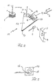
- Fig. 2 schematically shows this procedure.
- a label 1 is picked up by a gripper 10, for example loaded with vacuum, from a label stack 1 'and passed over by means of the gripper 10 in the direction of the arrow to a preforming device 11 which has a circular-sector-shaped plate 12 on which guide tracks 13 are formed, in which there are no circular paths shown, acted upon by vacuum grippers are guided displaceably, which take over the label 1 of the gripper 10 and lead to a mold block 14, the preforming cavity 15 corresponds to the mold cavity 3 of the injection mold 4.
- the mold block 14 is provided adjacent to the guideways 13 with a slot 16 extending in the axial direction of the deforming cavity 15, through which the label is inserted into the preforming cavity 15, in which it engages along the inner circumferential wall of the cone-shaped recess.
- the preformed label is transferred by means of the transfer tool 2 from the preforming device 11 to the mold cavity 3 of the injection molding machine, another label can already be removed from the stack 1 'and transferred to the preforming device 11 so that after closing the injection mold 4 and the injection molding process already a further preformed label for the transfer tool 2 is provided and can be worked with a high overall clock sequence.
- the label 1 can be preformed into the shape corresponding to a frusto-conical cup, the label 1 cut to form a segment of a circular ring sector is moved around a circular center 17 on a circular arc, the radius of the guide track 13 corresponding to the radius of curvature of the label.
- the label 1 on the circular arcuate guide track 13 is a development of the inner circumference of the preforming cavity 15.
- an in Fig. 2 not shown guide plate may be provided on the slot 16, which serves as a guide for the label.
- the guideway 13 may extend to the slot 16 and possibly also around the inner circumference of the preform cavity to facilitate or secure the winding of the label by the grippers guided in the guideway.
- Fig. 3 shows, as an example, such a curved insertion slot 16 in a view of the preforming cavity 15 from the side of the engagement of the transfer tool 2.
- preforming device 11 other preforming devices may be provided depending on another shape of an injection molded article. Accordingly, the interposition of a preforming device can also be provided in the production of a differently shaped injection-molded article, on the outside of which a label or another application is to be attached.
- Fig. 4 shows a mold block 14 'with an approximately rectangular preform cavity 15'.
- a preform cavity 15' Along one longitudinal side of the preforming cavity opens the slot 16 for insertion of the label 1.
- a support core 18 is provided, which only during the Vorformvorgangs in the Preform cavity 15 'is used. As a result, a gap is formed along the circumference of the preforming cavity 15 ', through which the label 1 is guided.
- the support core 18 can be inserted by means of a gripper, not shown, in the preform and taken out again after the preforming, so that the transfer tool 2 can engage to receive the preformed label.
- the support core 18 from one or the other side of the open on both sides of the preform and be extended.
- Fig. 4 shows suction means 19, for example holes, which are subjected to vacuum, which are at least partially arranged around the circumference of the preform cavity 15 '. After preforming and removing the support core 18, the label can be held snugly against the preform by these suction means 19.
- suction devices 19 may be provided, for example, only on the long sides and in particular on the narrow radii of the preforming cavity 15 'in connection with a support core 18 or even without a support core 18.
Landscapes
- Engineering & Computer Science (AREA)
- Manufacturing & Machinery (AREA)
- Mechanical Engineering (AREA)
- Injection Moulding Of Plastics Or The Like (AREA)
- Moulds For Moulding Plastics Or The Like (AREA)
- Diaphragms For Electromechanical Transducers (AREA)
- Blow-Moulding Or Thermoforming Of Plastics Or The Like (AREA)
Abstract
Description
Die Erfindung betrifft eine Vorrichtung nach dem Oberbegriff des Anspruchs 1 sowie ein Verfahren nach dem Oberbegriff des Anspruchs 5.The invention relates to a device according to the preamble of
Aus
Aus
Bei diesem bekannten Verfahren benötigt das Überführungswerkzeug zum Aufwickeln des Etiketts eine gewisse Zeit, bevor das Überführungswerkzeug in den Formhohlraum eingefahren werden kann, während der Spritzgießvorgang selbst relativ schnell abläuft. Deshalb muss die Spritzgießform eine gewisse Zeit untätig bereit gehalten werden, während das Etikett auf dem Überführungswerkzeug aufgewickelt und in den Formhohlraum überführt wird. Durch diese längere Taktzeit des Aufnehmens und Aufwickeln des Etiketts mittels des Überführungswerkzeugs gegenüber der Taktzeit der Spritzgießmaschine kann deren Kapazität nicht voll ausgenutzt werden.In this known method, the transfer tool for winding the label takes a certain time before the transfer tool can be retracted into the mold cavity, while the injection molding itself is relatively fast. Therefore, the injection mold must be held idle for some time while the label is being wound on the transfer tool and transferred to the mold cavity. Due to this longer cycle time of receiving and winding the label by means of the transfer tool with respect to the cycle time of the injection molding machine whose capacity can not be fully utilized.
Der Erfindung liegt die Aufgabe zugrunde, eine Vorrichtung und ein Verfahren der eingangs angegebenen Art so auszubilden, dass die Kapazität der Spritzgießmaschine besser ausgenutzt werden kann. Ferner soll eine Vorrichtung vorgeschlagen werden, mittels der eine Erhöhung der Kapazität der Spritzgießmaschine erreichbar ist.The invention has the object of providing a device and a method of the type described in such a way that the capacity of the injection molding machine can be better utilized. Furthermore, a device is to be proposed, by means of which an increase in the capacity of the injection molding machine can be achieved.
Diese Aufgabe wird hinsichtlich der Vorrichtung durch die Merkmale im kennzeichnenden Teil des Anspruchs 1 gelöst. Dadurch kann das Überführungswerkzeug in schneller Taktfolge das Etikett aus der Vorformeinrichtung aufnehmen und in den Formhohlraum überführen, so dass während des Überführens eines Etiketts aus der Vorformeinrichtung in den Formhohlraum des Spritzgießwerkzeugs bereits ein weiteres Etikett in der Vorformeinrichtung vorgeformt und für die Übernahme durch das Überfiihrungswerkzeug bereitgestellt werden kann. Durch die Zwischenschaltung eines Vorformvorganges des Etiketts kann insgesamt mit einer höheren Taktfolge gearbeitet werden, die zu einer hohen Auslastung der Spritzgießmaschine führt.This object is achieved with respect to the device by the features in the characterizing part of
Die Aufgabe zur Erhöhung der Kapazität einer Spritzgießmaschine wird auch durch die Merkmale des Kennzeichnenden Teils von Anspruch 5 gelöst.The task of increasing the capacity of an injection molding machine is also solved by the features of the characterizing part of claim 5.
Die Erfindung wird beispielsweise anhand der Zeichnung näher erläutert. Es zeigen
- Fig. 1
- schematisch die einzelnen Schritte des Überführens eines Etiketts in den Formhohl- raum bei dem bekannten Verfahren,
- Fig. 2
- in entsprechender Darstellung die Schrittfolge bei dem erfindungsgemäßen Verfah- ren mit einer Vorformeinrichtung,
- Fig. 3
- eine Vorderansicht des Vorformblocks, und
- Fig. 4
- schematisch einen Stützkern in der Vorform
- Fig. 1
- 1 schematically the individual steps of transferring a label into the mold cavity in the known method,
- Fig. 2
- in a corresponding representation, the sequence of steps in the method according to the invention with a preforming device,
- Fig. 3
- a front view of the preforming block, and
- Fig. 4
- schematically a support core in the preform
Gegenüber dem in
Während das vorgeformte Etikett mittels des Überführungswerkzeugs 2 von der Vorformeinrichtung 11 zum Formhohlraum 3 der Spritzgießmaschine überführt wird, kann bereits ein weiteres Etikett vom Stapel 1' abgenommen und in die Vorformeinrichtung 11 überführt werden, so dass nach dem Schließen der Spritzgießform 4 und dem Spritzgießvorgang bereits ein weiteres vorgeformtes Etikett für das Überführungswerkzeug 2 bereitgestellt ist und insgesamt mit einer hohen Taktfolge gearbeitet werden kann.While the preformed label is transferred by means of the
Damit das Etikett 1 in die einem kegelstumpfförmigen Becher entsprechende Form vorgeformt werden kann, wird das als Ausschnitt eines Kreisringsektors zugeschnittene Etikett 1 auf einer Kreisbogenbahn um einen Kreismittelpunkt 17 bewegt, wobei der Radius der Führungsbahn 13 dem Radius der Krümmung des Etiketts entspricht. Mit anderen Worten stellt das Etikett 1 auf der kreisbogenförmigen Führungsbahn 13 eine Abwicklung des Innenumfangs des Vorformhohlraums 15 dar.So that the
Damit das Etikett beim Einführen in den Schlitz 16 des Formblocks 14 sich an den Innenumfang des Vorformhohlraums 15 anlegt, kann ein in
Auch ist es möglich, den Schlitz 16 gekrümmt auszugestalten, so dass er etwa tangential zur Innenumfangswand des Vorformhohlraums 15 in diesen mündet, um das Anlegen des Etiketts an der Innenwand des Vorformhohlraums zu begünstigen.
Anstelle der beschriebenen Vorformeinrichtung 11 können in Abhängigkeit von einer anderen Gestalt eines Spritzgussartikels auch andere Vorformeinrichtungen vorgesehen werden. Entsprechend kann die Zwischenschaltung einer Vorformeinrichtung auch bei der Herstellung eines anders gestalteten Spritzgußartikels vorgesehen werden, auf dessen Außenseite ein Etikett oder eine andere Applikation anzubringen ist.Instead of the described preforming
Wenn beispielsweise größere Spritzgussartikel wie Eimer oder Spritzgussartikel mit einer großen Seitenlänge, beispielsweise bei einem etwa rechteckigen Behälter, vorgesehen werden, ist es zweckmäßig, den Vorformvorgang durch eine Hilfseinrichtung zu unterstützen.For example, if larger injection-molded articles such as pails or injection-molded articles with a large side-length, for example an approximately rectangular container, are provided, it is expedient to assist the preforming operation by an auxiliary device.
Der Stützkern 18 kann mittels eines nicht dargestellten Greifers in die Vorform eingeführt und nach dem Vorformvorgang wieder herausgenommen werden, damit das Überführungswerkzeug 2 zur Aufnahme des vorgeformten Etiketts eingreifen kann. Hierbei kann der Stützkern 18 von der einen oder anderen Seite der auf beiden Seiten offenen Vorform ein- und ausgefahren werden.The
Es können auch in anderer Weise vorgeformte Applikationen bzw. Etiketten in bereits vorgeformtem Zustand in die Vorform 14, 15 eingesetzt und dann von dem Überführungswerkzeug 2 in den Formhohlraum 3 des Spritzgießwerkzeugs überführt werden. Auf diese Weise wird eine Erhöhung der Taktzeit der Spritzgießmaschine erreicht.It is also possible in other ways preformed applications or labels in pre-formed state in the
Claims (5)
- Device for fabricating an injection molded article, for example a beaker, on whose outer circumference a label is arranged, comprising:- an injection mold (4) having two mold halves which, in the closed state, form a mold cavity (3) corresponding to the shape of the article to be fabricated,- a transfer tool (2) by means of which the label is transferable into the mold cavity (3) of a mold half (4),- a preforming means (11), in which the label (1) is preformed substantially into the shape in which the label is to be inserted in the mold cavity (3) of one mold half,characterised in that- in addition, a guideway (13) is provided, along which at least one gripper for the label is guided, and a forming block (14) is provided having a preform cavity (15) corresponding to the mold cavity (3) of the injection molding tool (4), wherein in the forming block (14) a slit (16) is formed near the guideway (13) for taking up the label (1), and- the transfer tool (2) takes up the preformed label out of the preforming means (11) and transfers it to the injection mold (4).
- Device according to claim 1, in which the guideway (13) is formed curved in a circular arc shape and the preform cavity (15) is formed in a truncated cone shape, wherein the radius of curvature of the guideway (13) lies on the side of the smallest diameter of the preform cavity (15).
- Device according to one of claims 1 or 2, wherein a supporting core (18) is insertable in the preform cavity (15') for guiding the label (1) during preforming.
- Device according to one of claims 1 to 3, wherein at least partially on the inner circumference of the preform cavity (15') suction means (19) are provided for holding the label (1) in the preformed shape.
- Method for fabricating an injection molded article, for example a beaker, on whose outer circumference a label is arranged, comprising the following steps:- providing an injection mold (4) having two mold halves which, in the closed state, form a mold cavity (3) corresponding to the shape of the article to be fabricated,- placing the label (1) on a transfer tool (2),- transferring the label into the mold cavity (3) of the one mold half by means of the transfer tool,- whereupon after positioning of the label in the mold cavity (3) the transfer tool (2) is moved out of the mold cavity (3) and the mold halves are closed for injection molding, wherein- the label (1) is preformed in a preforming means (11) into the shape for insertion into the mold cavity (3) before it is placed on the transfer tool (2), and- transferred by the transfer tool (2) from the preforming means (11) into the mold cavity (3),characterised in that a device according to claim 1 is used.
Applications Claiming Priority (3)
| Application Number | Priority Date | Filing Date | Title |
|---|---|---|---|
| DE10231654 | 2002-07-12 | ||
| DE10231654A DE10231654A1 (en) | 2002-07-12 | 2002-07-12 | Method and device for producing an injection molded article, on the outer circumferential surface of which a label is arranged |
| PCT/EP2003/007550 WO2004007167A1 (en) | 2002-07-12 | 2003-07-11 | Method and device for producing an injection moulded article, to the external peripheral surface of which an element, e.g. a label is applied |
Publications (2)
| Publication Number | Publication Date |
|---|---|
| EP1523402A1 EP1523402A1 (en) | 2005-04-20 |
| EP1523402B1 true EP1523402B1 (en) | 2011-04-13 |
Family
ID=30009938
Family Applications (1)
| Application Number | Title | Priority Date | Filing Date |
|---|---|---|---|
| EP03763822A Expired - Lifetime EP1523402B1 (en) | 2002-07-12 | 2003-07-11 | Device and method for producing an injection moulded article to the external peripheral surface of which a label is applied |
Country Status (6)
| Country | Link |
|---|---|
| US (1) | US20060163779A1 (en) |
| EP (1) | EP1523402B1 (en) |
| AT (1) | ATE505311T1 (en) |
| AU (1) | AU2003246686A1 (en) |
| DE (2) | DE10231654A1 (en) |
| WO (1) | WO2004007167A1 (en) |
Families Citing this family (6)
| Publication number | Priority date | Publication date | Assignee | Title |
|---|---|---|---|---|
| DE10331519A1 (en) * | 2003-07-11 | 2005-02-03 | Hekuma Gmbh | Handling system for an injection molding machine and method for introducing an application into the injection mold |
| AT500747A1 (en) * | 2004-08-20 | 2006-03-15 | Peter Steiner | METHOD AND DEVICE FOR PRODUCING A FILM OR BZW. COATING COATED CONTAINERS AND CONTAINERS |
| DE102004045459A1 (en) * | 2004-09-20 | 2006-03-30 | Hekuma Gmbh | Method of applying electronic product labels to thermoformed articles |
| DE102005004396A1 (en) * | 2005-01-31 | 2006-08-03 | Hekuma Gmbh | Label placement onto inner surface of cylindrical injection molding tool involves alignment of label on holding mandrel then moves to molding tool where label is transferred to tool wall and held in position |
| CH701890A2 (en) * | 2009-09-30 | 2011-03-31 | Beck Automation Ag | Label transfer device for an IML process. |
| US8616869B2 (en) * | 2010-01-11 | 2013-12-31 | Vention Medical, Inc. | In-mold labeling apparatus and method |
Family Cites Families (6)
| Publication number | Priority date | Publication date | Assignee | Title |
|---|---|---|---|---|
| DE1629706A1 (en) * | 1967-05-31 | 1971-02-04 | Lissmann Alkor Werk | Process for the production of injection molded parts with surface coating |
| DE2656965B2 (en) * | 1976-12-16 | 1979-07-19 | Gebr. Happich Gmbh, 5600 Wuppertal | Process for the back-foaming of preformed thermoplastic semi-rigid films, in particular for the production of dashboards for vehicles |
| DE69010968T2 (en) | 1989-04-28 | 1994-11-17 | Fuji Seal Ind Co Ltd | Method for manufacturing labeled articles, method for manufacturing labeled containers according to this method and apparatus for preforming labels for use in carrying out this method. |
| US5614146A (en) * | 1992-04-06 | 1997-03-25 | Sumitomo Heavy Industries, Ltd. | Method and apparatus of supplying labels to injection mold |
| IL117081A (en) * | 1996-02-08 | 2000-02-29 | Lotemplast Plastic Product Com | In-mold decoration of substantially tubular objects |
| NL1002696C2 (en) * | 1996-03-25 | 1997-09-26 | Simco Nederland | Method and device for manufacturing an injection molded article, as well as an article manufactured therewith. |
-
2002
- 2002-07-12 DE DE10231654A patent/DE10231654A1/en not_active Withdrawn
-
2003
- 2003-07-11 DE DE50313618T patent/DE50313618D1/en not_active Expired - Lifetime
- 2003-07-11 WO PCT/EP2003/007550 patent/WO2004007167A1/en not_active Ceased
- 2003-07-11 EP EP03763822A patent/EP1523402B1/en not_active Expired - Lifetime
- 2003-07-11 AU AU2003246686A patent/AU2003246686A1/en not_active Abandoned
- 2003-07-11 US US10/521,046 patent/US20060163779A1/en not_active Abandoned
- 2003-07-11 AT AT03763822T patent/ATE505311T1/en active
Also Published As
| Publication number | Publication date |
|---|---|
| WO2004007167A1 (en) | 2004-01-22 |
| DE10231654A1 (en) | 2004-02-05 |
| DE50313618D1 (en) | 2011-05-26 |
| ATE505311T1 (en) | 2011-04-15 |
| AU2003246686A1 (en) | 2004-02-02 |
| US20060163779A1 (en) | 2006-07-27 |
| EP1523402A1 (en) | 2005-04-20 |
Similar Documents
| Publication | Publication Date | Title |
|---|---|---|
| DE69503421T2 (en) | Device and method for manufacturing plastic objects | |
| DE69810120T2 (en) | METHOD AND DEVICE FOR PRODUCING CONTAINERS WITH LABEL | |
| EP2599607B1 (en) | Device for injecting a plastic moulded part onto a functioning part for forming a multi-component part | |
| EP0062144A2 (en) | Method and apparatus for gauging biaxially oriented thermoplastic bodies | |
| EP3127675B1 (en) | Iml injection moulding parts handling device and method of operation | |
| DE10331519A1 (en) | Handling system for an injection molding machine and method for introducing an application into the injection mold | |
| DE2842515C2 (en) | Method for producing head pieces with a membrane for packaging containers made of laminate with a metallic barrier layer and device for carrying out the method | |
| EP1782936A2 (en) | Injection moulding apparatus | |
| EP1523402A1 (en) | Method and device for producing an injection moulded article, to the external peripheral surface of which an element, e.g. a label is applied | |
| EP1884342A2 (en) | Device and method for blow moulding hollow thermoplastic bodies | |
| WO2003037602A1 (en) | Device for removing an injection moulded substrate from an injection-moulding tool, and injection-moulding machine equipped with same | |
| DE2517534B2 (en) | MOLDING DEVICE FOR MANUFACTURING LABELED CONTAINERS | |
| CH701890A2 (en) | Label transfer device for an IML process. | |
| EP1163108B1 (en) | Method and device for producing a two-chamber tube | |
| EP4186674A1 (en) | Device for injection moulding a moulded part with an insert | |
| EP0810919A1 (en) | Injection moulding machine | |
| DE102010033391A1 (en) | Plastic preform (preform) for large-volume containers and method and apparatus for its production | |
| DE20211490U1 (en) | Device for producing an injection molded article, on the outer circumferential surface of which a label is arranged | |
| DE19854663A1 (en) | Film-covered plastic container closure manufacture by cutting film outside a mold and transferring to the mold cavity | |
| WO2015035970A1 (en) | Method for producing a product by means of a thermoforming or joining system, and a thermoforming or joining system | |
| EP1846214B1 (en) | Method and device for transferring a label to an injection mold | |
| WO2023094552A1 (en) | Method for producing a combination component and combination component | |
| EP1166992A1 (en) | Mould for multicomponent injection moulding of plastic toothbrush bodies for toothbrushes | |
| EP0297522A3 (en) | Method and apparatus for the manufacture of plastic articles | |
| EP0853812B1 (en) | Method and device for the final assembly of a computer keyboard |
Legal Events
| Date | Code | Title | Description |
|---|---|---|---|
| PUAI | Public reference made under article 153(3) epc to a published international application that has entered the european phase |
Free format text: ORIGINAL CODE: 0009012 |
|
| 17P | Request for examination filed |
Effective date: 20050210 |
|
| AK | Designated contracting states |
Kind code of ref document: A1 Designated state(s): AT BE BG CH CY CZ DE DK EE ES FI FR GB GR HU IE IT LI LU MC NL PT RO SE SI SK TR |
|
| AX | Request for extension of the european patent |
Extension state: AL LT LV MK |
|
| DAX | Request for extension of the european patent (deleted) | ||
| 17Q | First examination report despatched |
Effective date: 20100304 |
|
| GRAP | Despatch of communication of intention to grant a patent |
Free format text: ORIGINAL CODE: EPIDOSNIGR1 |
|
| RTI1 | Title (correction) |
Free format text: DEVICE AND METHOD FOR PRODUCING AN INJECTION MOULDED ARTICLE TO THE EXTERNAL PERIPHERAL SURFACE OF WHICH A LABEL IS APPLIED |
|
| GRAS | Grant fee paid |
Free format text: ORIGINAL CODE: EPIDOSNIGR3 |
|
| GRAA | (expected) grant |
Free format text: ORIGINAL CODE: 0009210 |
|
| AK | Designated contracting states |
Kind code of ref document: B1 Designated state(s): AT BE BG CH CY CZ DE DK EE ES FI FR GB GR HU IE IT LI LU MC NL PT RO SE SI SK TR |
|
| REG | Reference to a national code |
Ref country code: GB Ref legal event code: FG4D Free format text: NOT ENGLISH |
|
| REG | Reference to a national code |
Ref country code: CH Ref legal event code: EP |
|
| REG | Reference to a national code |
Ref country code: IE Ref legal event code: FG4D Free format text: LANGUAGE OF EP DOCUMENT: GERMAN |
|
| REF | Corresponds to: |
Ref document number: 50313618 Country of ref document: DE Date of ref document: 20110526 Kind code of ref document: P |
|
| REG | Reference to a national code |
Ref country code: DE Ref legal event code: R096 Ref document number: 50313618 Country of ref document: DE Effective date: 20110526 |
|
| REG | Reference to a national code |
Ref country code: NL Ref legal event code: VDEP Effective date: 20110413 |
|
| PG25 | Lapsed in a contracting state [announced via postgrant information from national office to epo] |
Ref country code: PT Free format text: LAPSE BECAUSE OF FAILURE TO SUBMIT A TRANSLATION OF THE DESCRIPTION OR TO PAY THE FEE WITHIN THE PRESCRIBED TIME-LIMIT Effective date: 20110816 Ref country code: SE Free format text: LAPSE BECAUSE OF FAILURE TO SUBMIT A TRANSLATION OF THE DESCRIPTION OR TO PAY THE FEE WITHIN THE PRESCRIBED TIME-LIMIT Effective date: 20110413 |
|
| REG | Reference to a national code |
Ref country code: IE Ref legal event code: FD4D |
|
| PG25 | Lapsed in a contracting state [announced via postgrant information from national office to epo] |
Ref country code: CY Free format text: LAPSE BECAUSE OF FAILURE TO SUBMIT A TRANSLATION OF THE DESCRIPTION OR TO PAY THE FEE WITHIN THE PRESCRIBED TIME-LIMIT Effective date: 20110413 Ref country code: SI Free format text: LAPSE BECAUSE OF FAILURE TO SUBMIT A TRANSLATION OF THE DESCRIPTION OR TO PAY THE FEE WITHIN THE PRESCRIBED TIME-LIMIT Effective date: 20110413 Ref country code: FI Free format text: LAPSE BECAUSE OF FAILURE TO SUBMIT A TRANSLATION OF THE DESCRIPTION OR TO PAY THE FEE WITHIN THE PRESCRIBED TIME-LIMIT Effective date: 20110413 Ref country code: GR Free format text: LAPSE BECAUSE OF FAILURE TO SUBMIT A TRANSLATION OF THE DESCRIPTION OR TO PAY THE FEE WITHIN THE PRESCRIBED TIME-LIMIT Effective date: 20110714 Ref country code: ES Free format text: LAPSE BECAUSE OF FAILURE TO SUBMIT A TRANSLATION OF THE DESCRIPTION OR TO PAY THE FEE WITHIN THE PRESCRIBED TIME-LIMIT Effective date: 20110724 |
|
| PG25 | Lapsed in a contracting state [announced via postgrant information from national office to epo] |
Ref country code: NL Free format text: LAPSE BECAUSE OF FAILURE TO SUBMIT A TRANSLATION OF THE DESCRIPTION OR TO PAY THE FEE WITHIN THE PRESCRIBED TIME-LIMIT Effective date: 20110413 |
|
| BERE | Be: lapsed |
Owner name: HEKUMA G.M.B.H. Effective date: 20110731 |
|
| PG25 | Lapsed in a contracting state [announced via postgrant information from national office to epo] |
Ref country code: EE Free format text: LAPSE BECAUSE OF FAILURE TO SUBMIT A TRANSLATION OF THE DESCRIPTION OR TO PAY THE FEE WITHIN THE PRESCRIBED TIME-LIMIT Effective date: 20110413 Ref country code: IE Free format text: LAPSE BECAUSE OF FAILURE TO SUBMIT A TRANSLATION OF THE DESCRIPTION OR TO PAY THE FEE WITHIN THE PRESCRIBED TIME-LIMIT Effective date: 20110413 Ref country code: CZ Free format text: LAPSE BECAUSE OF FAILURE TO SUBMIT A TRANSLATION OF THE DESCRIPTION OR TO PAY THE FEE WITHIN THE PRESCRIBED TIME-LIMIT Effective date: 20110413 |
|
| PLBE | No opposition filed within time limit |
Free format text: ORIGINAL CODE: 0009261 |
|
| STAA | Information on the status of an ep patent application or granted ep patent |
Free format text: STATUS: NO OPPOSITION FILED WITHIN TIME LIMIT |
|
| PG25 | Lapsed in a contracting state [announced via postgrant information from national office to epo] |
Ref country code: SK Free format text: LAPSE BECAUSE OF FAILURE TO SUBMIT A TRANSLATION OF THE DESCRIPTION OR TO PAY THE FEE WITHIN THE PRESCRIBED TIME-LIMIT Effective date: 20110413 Ref country code: DK Free format text: LAPSE BECAUSE OF FAILURE TO SUBMIT A TRANSLATION OF THE DESCRIPTION OR TO PAY THE FEE WITHIN THE PRESCRIBED TIME-LIMIT Effective date: 20110413 Ref country code: RO Free format text: LAPSE BECAUSE OF FAILURE TO SUBMIT A TRANSLATION OF THE DESCRIPTION OR TO PAY THE FEE WITHIN THE PRESCRIBED TIME-LIMIT Effective date: 20110413 Ref country code: MC Free format text: LAPSE BECAUSE OF NON-PAYMENT OF DUE FEES Effective date: 20110731 |
|
| REG | Reference to a national code |
Ref country code: CH Ref legal event code: PL |
|
| 26N | No opposition filed |
Effective date: 20120116 |
|
| PG25 | Lapsed in a contracting state [announced via postgrant information from national office to epo] |
Ref country code: BE Free format text: LAPSE BECAUSE OF NON-PAYMENT OF DUE FEES Effective date: 20110731 Ref country code: LI Free format text: LAPSE BECAUSE OF NON-PAYMENT OF DUE FEES Effective date: 20110731 Ref country code: CH Free format text: LAPSE BECAUSE OF NON-PAYMENT OF DUE FEES Effective date: 20110731 |
|
| REG | Reference to a national code |
Ref country code: DE Ref legal event code: R097 Ref document number: 50313618 Country of ref document: DE Effective date: 20120116 |
|
| PG25 | Lapsed in a contracting state [announced via postgrant information from national office to epo] |
Ref country code: IT Free format text: LAPSE BECAUSE OF FAILURE TO SUBMIT A TRANSLATION OF THE DESCRIPTION OR TO PAY THE FEE WITHIN THE PRESCRIBED TIME-LIMIT Effective date: 20110413 |
|
| REG | Reference to a national code |
Ref country code: AT Ref legal event code: MM01 Ref document number: 505311 Country of ref document: AT Kind code of ref document: T Effective date: 20110711 |
|
| PG25 | Lapsed in a contracting state [announced via postgrant information from national office to epo] |
Ref country code: AT Free format text: LAPSE BECAUSE OF NON-PAYMENT OF DUE FEES Effective date: 20110711 |
|
| PG25 | Lapsed in a contracting state [announced via postgrant information from national office to epo] |
Ref country code: LU Free format text: LAPSE BECAUSE OF NON-PAYMENT OF DUE FEES Effective date: 20110711 |
|
| PG25 | Lapsed in a contracting state [announced via postgrant information from national office to epo] |
Ref country code: BG Free format text: LAPSE BECAUSE OF FAILURE TO SUBMIT A TRANSLATION OF THE DESCRIPTION OR TO PAY THE FEE WITHIN THE PRESCRIBED TIME-LIMIT Effective date: 20110713 |
|
| PG25 | Lapsed in a contracting state [announced via postgrant information from national office to epo] |
Ref country code: TR Free format text: LAPSE BECAUSE OF FAILURE TO SUBMIT A TRANSLATION OF THE DESCRIPTION OR TO PAY THE FEE WITHIN THE PRESCRIBED TIME-LIMIT Effective date: 20110413 |
|
| PG25 | Lapsed in a contracting state [announced via postgrant information from national office to epo] |
Ref country code: HU Free format text: LAPSE BECAUSE OF FAILURE TO SUBMIT A TRANSLATION OF THE DESCRIPTION OR TO PAY THE FEE WITHIN THE PRESCRIBED TIME-LIMIT Effective date: 20110413 |
|
| REG | Reference to a national code |
Ref country code: FR Ref legal event code: PLFP Year of fee payment: 13 |
|
| REG | Reference to a national code |
Ref country code: FR Ref legal event code: PLFP Year of fee payment: 14 |
|
| PGFP | Annual fee paid to national office [announced via postgrant information from national office to epo] |
Ref country code: DE Payment date: 20160726 Year of fee payment: 14 Ref country code: GB Payment date: 20160722 Year of fee payment: 14 |
|
| PGFP | Annual fee paid to national office [announced via postgrant information from national office to epo] |
Ref country code: FR Payment date: 20160725 Year of fee payment: 14 |
|
| REG | Reference to a national code |
Ref country code: DE Ref legal event code: R119 Ref document number: 50313618 Country of ref document: DE |
|
| GBPC | Gb: european patent ceased through non-payment of renewal fee |
Effective date: 20170711 |
|
| REG | Reference to a national code |
Ref country code: FR Ref legal event code: ST Effective date: 20180330 |
|
| PG25 | Lapsed in a contracting state [announced via postgrant information from national office to epo] |
Ref country code: GB Free format text: LAPSE BECAUSE OF NON-PAYMENT OF DUE FEES Effective date: 20170711 Ref country code: DE Free format text: LAPSE BECAUSE OF NON-PAYMENT OF DUE FEES Effective date: 20180201 |
|
| PG25 | Lapsed in a contracting state [announced via postgrant information from national office to epo] |
Ref country code: FR Free format text: LAPSE BECAUSE OF NON-PAYMENT OF DUE FEES Effective date: 20170731 |