EP1522878B1 - Method for determining the displacement of luggage in order to scan a suspicious region in the luggage - Google Patents
Method for determining the displacement of luggage in order to scan a suspicious region in the luggage Download PDFInfo
- Publication number
- EP1522878B1 EP1522878B1 EP04023811A EP04023811A EP1522878B1 EP 1522878 B1 EP1522878 B1 EP 1522878B1 EP 04023811 A EP04023811 A EP 04023811A EP 04023811 A EP04023811 A EP 04023811A EP 1522878 B1 EP1522878 B1 EP 1522878B1
- Authority
- EP
- European Patent Office
- Prior art keywords
- luggage
- item
- examination system
- image
- change
- Prior art date
- Legal status (The legal status is an assumption and is not a legal conclusion. Google has not performed a legal analysis and makes no representation as to the accuracy of the status listed.)
- Expired - Lifetime
Links
- 238000000034 method Methods 0.000 title claims description 45
- 238000006073 displacement reaction Methods 0.000 title description 3
- 238000007781 pre-processing Methods 0.000 claims abstract description 18
- 230000003287 optical effect Effects 0.000 claims abstract description 7
- 238000004458 analytical method Methods 0.000 claims description 27
- 230000008859 change Effects 0.000 claims description 26
- 238000002594 fluoroscopy Methods 0.000 claims description 21
- 238000013519 translation Methods 0.000 claims description 8
- 230000009466 transformation Effects 0.000 claims description 7
- 230000008878 coupling Effects 0.000 claims description 4
- 238000010168 coupling process Methods 0.000 claims description 4
- 238000005859 coupling reaction Methods 0.000 claims description 4
- 238000000844 transformation Methods 0.000 claims description 2
- 238000000605 extraction Methods 0.000 description 12
- 238000004364 calculation method Methods 0.000 description 9
- 230000014616 translation Effects 0.000 description 7
- 238000001514 detection method Methods 0.000 description 6
- 238000011161 development Methods 0.000 description 6
- 230000018109 developmental process Effects 0.000 description 6
- 238000003384 imaging method Methods 0.000 description 5
- 238000011835 investigation Methods 0.000 description 5
- 238000010586 diagram Methods 0.000 description 4
- 230000005484 gravity Effects 0.000 description 4
- 230000000052 comparative effect Effects 0.000 description 3
- 238000012545 processing Methods 0.000 description 2
- 238000012935 Averaging Methods 0.000 description 1
- 230000009102 absorption Effects 0.000 description 1
- 238000010521 absorption reaction Methods 0.000 description 1
- 230000004308 accommodation Effects 0.000 description 1
- 238000003556 assay Methods 0.000 description 1
- 230000008901 benefit Effects 0.000 description 1
- 230000015572 biosynthetic process Effects 0.000 description 1
- 238000010276 construction Methods 0.000 description 1
- 230000002596 correlated effect Effects 0.000 description 1
- 230000001419 dependent effect Effects 0.000 description 1
- 238000004141 dimensional analysis Methods 0.000 description 1
- 238000011156 evaluation Methods 0.000 description 1
- 239000002360 explosive Substances 0.000 description 1
- 238000010191 image analysis Methods 0.000 description 1
- 238000002595 magnetic resonance imaging Methods 0.000 description 1
- 238000013507 mapping Methods 0.000 description 1
- 239000011159 matrix material Substances 0.000 description 1
- 238000005259 measurement Methods 0.000 description 1
- 239000002184 metal Substances 0.000 description 1
- 238000012805 post-processing Methods 0.000 description 1
- 230000009467 reduction Effects 0.000 description 1
- 238000000926 separation method Methods 0.000 description 1
- 238000011524 similarity measure Methods 0.000 description 1
- 238000012360 testing method Methods 0.000 description 1
- 238000012546 transfer Methods 0.000 description 1
Images


Classifications
-
- G—PHYSICS
- G01—MEASURING; TESTING
- G01V—GEOPHYSICS; GRAVITATIONAL MEASUREMENTS; DETECTING MASSES OR OBJECTS; TAGS
- G01V5/00—Prospecting or detecting by the use of ionising radiation, e.g. of natural or induced radioactivity
- G01V5/20—Detecting prohibited goods, e.g. weapons, explosives, hazardous substances, contraband or smuggled objects
- G01V5/22—Active interrogation, i.e. by irradiating objects or goods using external radiation sources, e.g. using gamma rays or cosmic rays
Definitions
- the invention relates to a method for determining the change in position of a piece of luggage for examining a suspicious region in this item of luggage.
- the object of the invention is therefore to provide a method which, on the one hand, has a high detection rate with a simultaneously low false alarm rate, but has a significantly shorter test time than the known methods with the aforementioned framework conditions.
- the relative change in position of the item of luggage is calculated by means of a comparison of two recordings of the same item of luggage, which were recorded in different examination systems.
- the second investigation system By knowing the coordinates of a suspected region, which were obtained in the first investigation system, it is possible in the second investigation system to examine only this suspicious region whose coordinates from the first investigation system were now converted to the coordinates in the second investigation system. This saves Take the time to examine all the pieces of baggage that are already identified as non-suspicious.
- every imaging system is possible, as far as the calculation of the rotation angles around the vertical and the horizontal as well as the translation is to take place.
- the suspect region is obtained in the first examination system is not essential to the invention, so that devices which operate according to completely different technological principles can be used for the first examination system and the second examination system.
- an X-ray fluoroscopy system is preferred in terms of examination of the suspect region, but the invention is by no means limited thereto. It is just as possible, for. B. perform a magnetic resonance imaging.
- the two examination systems can be far apart.
- the luggage to be examined can be carried by hand or transported by a vehicle, so that even a conveyor belt between them is unnecessary.
- the method according to the invention results in an enormous saving in terms of the analysis time combined with a high detection rate and a low false alarm rate.
- optical preprocessing means that the image information of a fluoroscopic image is manipulated in such a way that the function of the image registration with regard to accuracy and reliability is improved. This can be done, for example, by making a local averaging and median formation to reduce the noise.
- non-linear scale filters see G. Aubert & P. Kornprobst: Mathematical Problems in Image Processing: Partial Differential Equations and the Calculus of Variations, Springer, New York, 2002
- a further advantageous development of the invention provides that an output of a set of first and / or second rotation angles takes place with ambiguities. Although it is therefore necessary to study several suspicious regions, only a few regions remain regularly, so that there is a significant reduction in the number of regions to be examined in the item of luggage. At the same time the detection rate is kept high and the false alarm rate remains low. It is worked with the two hypotheses that the piece of luggage was flipped or not flipped, ie that it lies on the same side or on its opposite side. Ambiguities exist when the method can not clearly decide between these two hypotheses. An input of a probability measure or a confidence measure (a number or a vector of numbers which provides information about the reliability of a result) is preferred for the first and / or second rotation angles.
- a scoring of the found suspect regions is made and an examination of the respective region for which the angles with the highest probability measure have been found can be carried out first. This makes it more likely that dangerous contents of the baggage will be found faster.
- a probability measure is understood to be a value which provides information about how high the Reliability of the determined values for translation and angle of rotation (which also includes the indication whether the item of luggage was flipped or not). This probability measure can be used to let other instances (both a human and a machine) decide on the quality of image registration. For example, a threshold value is used below which the entire item of luggage in the second examination system has to be scanned again.
- a further advantageous development of the invention provides that the determination of the change in position of the item of baggage on the basis of global features, in particular correlation, "mutual information" (see description to FIG. 3) or radial measured variables.
- one of the two recordings of the item of luggage is rotated until it is the most similar to the other recording.
- the fulcrum must be defined in both pictures.
- I i, j is the intensity value of the image at point ( i, j ) .
- the recording is divided into N angle segments (the evaluation takes place in each case in an angle range between ⁇ and ⁇ + ⁇ ), which can be obtained with different dimensions, for. Statistical moments. Then one compares the values of the N. segment with the values of N + n. Segment, where n corresponds to the angle increment. Preferably, this determination is coupled with a scale analysis. It compares the results on different length scales, ie at different resolutions, and combines these findings, resulting in a reduced computing time is obtained. Thus, the calculation time is reduced by a factor of 4 when the resolution is halved because fewer pixels need to be analyzed.
- a comparison measure is understood to mean a function which has the two recordings as input parameters and supplies a number or a vector. This output value is then related to the difference between the two images. The simplest example of this is the difference of the pixels. If this is small, then the two shots are the same.
- global features are understood to mean that all pixels of the image are used for image registration. This is in contrast to the local features given below, which are used as a subset of these entire pixels. The respective subset must be determined. One possibility for this is the detection of corners and edges.
- a further advantageous development of the invention provides that the determination of the change in position of the item of luggage is carried out on the basis of local features, in particular on the basis of "random sample consensus" (RANSAC), robust estimation method, Hough transformations or least square methods.
- RANSAC random sample consensus
- robust estimation method robust estimation method
- Hough transformations or least square methods are associated with each other by determining where a particular feature of the one shot is to be found in the second shot. This makes it possible to determine the information necessary for the transformation of the coordinates of the suspect region - namely the first angle of rotation about the vertical, the second angle of rotation about the horizontal and the translation - by which the features can be converted into one another.
- the determination of the change in the position of the item of luggage is particularly preferably made on the basis of a coupling of the analysis by means of global features with an analysis by means of local features.
- Such coupling may be accomplished, for example, by using both image registration methods and forming a weighted average of the two results. This weighted average may then serve as a function of the probability measure.
- Another coupling can also be done by using the local features only when the probability measure of the global features is not high enough. This gives a particularly reliable and quickly obtainable information about the transformation of the coordinates.
- a further advantageous development of the invention provides that the determination of the change in position takes place on the basis of local features on different length scales. For example, this can be done by performing the calculation on a length scale and comparing the results to a comparable analysis on a different length scale.
- the choice of local features will be made depending on the length scale. Here you select on each length scale the features that are best to measure there. This leads to a simplification of the determination of the change in the position of the item of luggage. For example, is used as a length scale 1, the original image of the recording. Length scale 2 then corresponds to the original image with a lower resolution (see also the scale pyramid in Jähne, Digital Image Processing, Springer 1997).
- a scale analysis is understood to mean that the resolution of the recordings is successively increased. Image registration is then performed at each resolution level. First of all, the image registration starts with a coarse resolution, for example the length scale 4. From this one obtains a situation with a confidence interval. Then one increases the resolution, for example to the length scale 3, and leaves the image registration only in the confidence interval run. These steps are performed up to the maximum resolution (original image of length scale 1).
- the advantage is on the one hand in the shortened computing time and on the other hand in the robustness of this method to geometric distortions, which can lead to misregistration especially at higher resolutions.
- a further advantageous embodiment of the invention provides that only the local features are used that are not inconsistent with the analysis based on the global features. This improves the allocation of local features.
- FIG. 1 shows a block diagram with a schematic illustration of a method for comparing the accommodation of a piece of luggage 4 and for determining the change in position of the item of luggage 4.
- a reference system which turns off on the conveyor belt. It is a Cartesian coordinate system whose X-axis is transverse to the direction of conveyance and whose zero point is at the edge of the conveyor belt. The Y-coordinate points against the direction of conveyance and starts at the edge of the suitcase. The Z-coordinate starts on the conveyor belt and points upwards. This results in a right-handed coordinate system.
- a single rotation angle refers to a rotation of the luggage item 4 about the Z-axis.
- the regularly required second rotation angle is replaced by the indication whether the item of luggage 4 has been flipped or not.
- flipping is meant here a rotation of the piece of luggage about 180 ° about the X-axis.
- the translation has yet to be defined. This is the displacement of the item of luggage 4 on the conveyor belt in the XY plane.
- a first X-ray fluoroscopic image 1 is recorded.
- the item of luggage 4 (see FIGS. 2, 3, 6 and 7) is located in a position held by the first X-ray fluoroscopy image 1.
- a second X-ray fluoroscopy image 2 of the same item of luggage 4 is taken up in a second position, which deviates regularly from the first position.
- both X-ray fluoroscopy images 1, 2 are each subjected to preprocessing 10, 20. In this case, both a geometric equalization, as well as an optical preprocessing of the intensities is made. Further details will be explained with reference to FIG. 2 ac below.
- a geometric transformation 31 of the images In addition to the image of the first stage of the first stage device, a first list 12 of coordinates of the first suspect regions 13 is also provided. After the position has been successfully determined via the position change calculation 30, a second list 22 having transformed second suspect regions 23 is calculated and output, which then relates to the second X-ray fluoroscopic image 2.
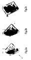
- FIG. 2 shows three phases with regard to the pre-processing 10 of a first X-ray fluoroscopy image 1, which is also representative of the second X-ray fluoroscopic image 2.
- the type of preprocessing 10, 20 depends on the transilluminators used and their imaging geometry. The example given here is a detector of L-shaped geometry.
- Fig. 2 a the originally recorded X-ray fluoroscopy image 1, 2 is shown.
- a first preprocessing step an optical calibration using the full dynamics of the intensity values is performed, a so-called histogram approximation (FIG. 2b).
- Fig. 2 c the result of the representation of the item of luggage 4 can be seen after performing a second step.
- the distorted picture was equalized. This is easily possible if the geometry of the X-ray fluoroscopy system, in particular the arrangement of the X-ray tube to the detector and the relative position of the object to both and the geometry of the detector are known.
- the two aforementioned steps jointly serve to provide images of different fluoroscopy devices on a common, comparable basis.
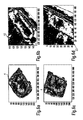
- Fig. 3 ad the four lowest levels of a scale pyramid are shown. These are used in the feature extraction 11, 21. In this case, the resolution of Fig. 3a increases to Fig. 3 d successively. In addition to the use of four levels of the scale pyramid, any other number of stages is possible.
- I 1 and I 2 correspond to the projections of the X-ray images on the conveyor belt.
- a transformation of the Cartesian coordinates into polar coordinates has been performed.
- a projection to other levels is just as possible.
- the image on the coarsest length scale (see Fig. 3a) consists only of about 40x40 pixels.
- the topology changes that always occur with rotated objects in x-ray images play a weaker role.
- the further analysis is initially only on the coarsest length scale. It is then successively extended to finer length scales with higher resolution.
- the first X-ray fluoroscopic image 1 which is regularly referred to as a first-stage image, it is compared with a prescanner image of the second X-ray radiograph 2 by means of a correlation method for different angles of rotation. This is also done with a 180 ° flipped case.
- the correlation measure between the normalized X-ray fluoroscopic images 1, 2 the above-mentioned measure C (I 1 (r, ⁇ ), I 2 ( r , ⁇ + ⁇ )) is used in the present example.
- I ⁇ 1,2 are the mean intensities of the image.
- I 1,2 ( r , ⁇ ) is the intensity value at r and ⁇ .
- the "mutual information" can be used.
- the three probability densities p ( a ) , p ( b ) and p ( a, b ) are calculated.
- p ( a ) and p ( b ) are the probability densities of certain amplitude values.
- p ( a, b ) is the probability density for a pixel to have a value a and a value b at the same time.
- the calculation of the correlation or the "mutual information" corresponds to the step of the feature extraction 11, 21 as well as in parts of the calculation of the position change 30.
- the image on the bottom scale is additionally rotated about its center of gravity.
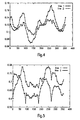
- Fig. 4 the course of the dimensions for different angles of rotation is shown.
- the image with the coarsest length scale of the second X-ray fluoroscopy image 2 was rotated about its center of gravity and compared with the image of the first-stage device, ie the first X-ray fluoroscopic image 1 with respect to its center of gravity.
- the dimensional analysis on the coarsest length scale provides different maximum points. These will be used in the next step to more precisely determine the dimensions at the higher levels. This means that instead of voting all the rotation angles at each level, only the best candidates at the next higher level are used.
- the correlation results are analyzed and the angle of rotation of the item of luggage 4 is determined.
- Other information can and will be taken into account.
- the rotation angles of the two X-ray fluoroscopy images 1, 2 were calculated and compared with the result of the method described above.
- the maxima of the various dimensions of the flipped or non-flipped luggage 4 were compared and evaluated. In the event that the analysis can not determine a unique angle, then optionally more angles are output. Further refinement is possible using local features (see below for FIG. 6 ad).
- the lines shown in FIG. 4 belong firstly to a non-tilted case (line 1) and in the other case to a tilted case (line 2).
- the correlation for different angular dimensions of the first X-ray fluoroscopic image 1 with the second X-ray fluoroscopic image 2 is given on the coarsest length scale. Again, two lines are shown, with one line (line 1) belonging to a non-flipped case and the second line (line 2) belonging to a flipped case.
- FIG. 6a-d the method of feature extraction 11, 21 is illustrated by means of local features.
- FIG. 6 a and 6 c the same piece of luggage 4 is shown in different positions.
- FIG. 6 b shows a first image detail 13 from FIG. 6 a, in which a bottle can be seen. The same bottle has been found in Fig. 6d after carrying out the method according to the invention.
- the location determination by means of local features can be carried out on its own or as a post-processing step for a position determination with the aid of the global features (as described above for FIGS. 3 ad).
- the preprocessing 10, 20 was previously performed for this purpose. Other steps may be needed, depending on how the local characteristics are defined.
- different first image sections 13 with local features are determined from the first X-ray fluoroscopic image 1. This can be achieved, for example, by determining edges, corners or areas of high intensity.
- a determination of the entropy of the local amplitude statistics can also take place.
- Characteristic of the amplitude statistics is that it contains no spatial information. It is therefore independent of the relative position of individual objects of the first image section 13.
- the features of their amplitude statistics are described below. It is assumed that the two image sections 13, 23 of FIGS. 6 b and 6 d, which are most similar, contain the sought-after feature. In the method presented here, the difference between the different moments of the amplitude statistics and the entropy was used as a measure of similarity. Other similarity measures are, for example, the value of the convolution integral of the probability densities.
- a first image detail 13 (FIG. 6 b) was selected.
- a second image detail 23 with the same dimensions was sought, which resembles the first image detail 13 in its statistical properties. Since the second image section 23 of FIG. 6 b is a rectangle, the position of the item of luggage 4, however, passes between FIGS. 6 a and 6 c has changed a rotation, in Fig. 6 d, the bottle is not fully displayed. This problem could be avoided, for example, by the fact that no rectangular image sections 13, 23 are used, but circular.
- x i For each feature x i , it satisfies the applicable mapping equation (see also Richard Hartley and Andrew Zisserman in Multiple View Geometry in Computer Vision, Second Edition, Cambridge University Press, March 2004).
- 0 x ' i T F x i , F represents the fundamental matrix of the imaging system, x ' the imaged point and x the coordinates of the real point.
- a first X-ray fluoroscopic image 1 of a luggage item 4 from a first-stage device (left side) is compared with a second X-ray fluoroscopy image 2 of the same item of luggage 4 of a further X-ray fluoroscopic apparatus.
- the item of luggage 4 has been both turned and flipped here.
- an assignment of the first suspect region 13 (which is drawn in for clarity as a rectangle) to the second suspect region 23 is very well possible.
- a second-stage device only an analysis of the second suspect region 23 is performed, which was classified as suspicious in a first X-ray fluoroscopic image 1 in a first-stage device.
- the coordinates of the first suspect region 13 determined by the first-stage device and a line scan image are transmitted to the second-stage device. Since both devices are spatially separated from each other and the baggage item 4 is thus regularly brought from the first-stage device to the second-stage device via different transport systems, the coordinates of the new position of the baggage item 4 must be adjusted.
- the second stage device is also equipped with a line scanner.
- the two X-ray fluoroscopy images 1, 2 are each subjected to a preprocessing 10, 20 by means of a calibration, so that they are comparable with one another.
- a feature extraction 11, 21 by means of global and / or local features for each of the two X-ray fluoroscopy images 1, 2.
- the change in position of the object 4 can be calculated by means of a comparison. This makes it possible for only the second suspect region 23 to be analyzed in the second-stage device and not the entire object 4.
- the inventive method thus brings about a high degree of time savings in the analysis of the object 4 without the detection rate dropping or the false alarm rate increasing.
Landscapes
- Physics & Mathematics (AREA)
- High Energy & Nuclear Physics (AREA)
- Life Sciences & Earth Sciences (AREA)
- General Life Sciences & Earth Sciences (AREA)
- General Physics & Mathematics (AREA)
- Geophysics (AREA)
- Image Analysis (AREA)
- Analysing Materials By The Use Of Radiation (AREA)
- Image Processing (AREA)
Abstract
Description
Die Erfindung betrifft ein Verfahren zur Bestimmung der Lageänderung eines Gepäckstücks zur Untersuchung einer verdächtigen Region in diesem Gepäckstück.The invention relates to a method for determining the change in position of a piece of luggage for examining a suspicious region in this item of luggage.
Es ist heutzutage möglich, Gepäckstücke vollständig auf Sprengstoffe zu analysieren. Die zu Grunde liegenden Analyseverfahren erweisen sich dabei als sehr zuverlässig, aber auch als langwierig. Eine solche langwierige Analyse kann an Flughäfen nur in sogenannten Drittstufengeräten erfolgen. Dort fällt das Gepäckstückaufkommen deutlich geringer aus als bei den Erst- bzw. Zweitstufengeräten. Bei diesen Drittstufengeräten wird eine hohe Detektionsrate und eine niedrige Fehlalarmrate benötigt. Um ein solches Drittstufengerät auch als Zweitstufengerät verwenden zu können, muss die Analysezeit deutlich verringert werden.It is now possible to analyze baggage completely for explosives. The underlying analysis methods prove to be very reliable, but also tedious. Such a lengthy analysis can be done at airports only in so-called third-party devices. There, the baggage volume is significantly lower than in the first or second stage devices. These third-stage devices require a high detection rate and a low false alarm rate. In order to use such a third-stage device as a second-stage device, the analysis time must be significantly reduced.
Dieses Problem wurde bislang so gelöst, dass keine räumliche Trennung zwischen einem Erststufen- und einem Zweitstufengerät zugelassen wurde (siehe US 5,182,764) bzw. eine räumliche Verschiebung oder Drehung des Gepäckstücks verhindert wurde (siehe WO 03/065077 A2). Dies ist jedoch sehr aufwendig und in der Praxis kaum zu realisieren.This problem has been solved so far that no spatial separation between a first-stage and a second-stage device was approved (see US 5,182,764) or a spatial displacement or rotation of the luggage was prevented (see WO 03/065077 A2). However, this is very expensive and difficult to realize in practice.
Aufgabe der Erfindung ist es deswegen, ein Verfahren zur Verfügung zu stellen, das auf der einen Seite eine hohe Detektionsrate bei gleichzeitig niedriger Fehlalarmrate aufweist, jedoch gegenüber den bekannten Verfahren mit den vorgenannten Rahmenbedingungen eine deutlich kürzere Prüfzeit hat.The object of the invention is therefore to provide a method which, on the one hand, has a high detection rate with a simultaneously low false alarm rate, but has a significantly shorter test time than the known methods with the aforementioned framework conditions.
Die Aufgabe wird durch ein Verfahren mit den Merkmalen des Patentanspruchs 1 gelöst. Bei dem erfindungsgemäßen Verfahren wird mittels eines Vergleichs von zwei Aufnahmen des selben Gepäckstücks, die in unterschiedlichen Untersuchungssystemen aufgenommen wurden, die relative Lageänderung des Gepäckstücks berechnet. Durch die Kenntnis der Koordinaten einer verdächtigen Region, die im ersten Untersuchungssystem gewonnen wurden, ist es im zweiten Untersuchungssystem möglich, nur diese verdächtige Region, deren Koordinaten aus dem ersten Untersuchungssystem nun auf die Koordinaten im zweiten Untersuchungssystem umgerechnet wurden, näher zu untersuchen. Dadurch spart man sich die Zeit, die gesamten schon als nicht verdächtige Region identifizierten Teile des Gepäckstücks noch einmal zu untersuchen. Als erstes und zweites Untersuchungssystem ist jedes bildgebende System möglich, soweit die Berechnung der Drehwinkel um die Vertikale und die Horizontale sowie die Translation erfolgen soll. Dazu zählen sowohl Videobilder als auch Durchleuchtungsbilder, beispielsweise mittels Röntgenstrahlung. Wie die verdächtige Region im ersten Untersuchungssystem erhalten wird, ist nicht erfindungswesentlich, so dass für das erste Untersuchungssystem und das zweite Untersuchungssystem Geräte verwendet werden können, die nach vollkommen unterschiedlichen technologischen Prinzipien arbeiten. Für das zweite Untersuchungssystem wird hinsichtlich der Untersuchung der verdächtigen Region ein Röntgendurchleuchtungssystem bevorzugt, jedoch ist die Erfindung keines Falls darauf beschränkt. Es ist genauso möglich, z. B. eine Kernspintomographie durchzuführen. Darüber hinaus können die beiden Untersuchungssysteme auch weit voneinander entfernt sein. Das zu untersuchende Gepäckstück kann von Hand getragen oder über ein Fahrzeug transportiert werden, so dass selbst ein Förderband zwischen ihnen entbehrlich ist. Im Ergebnis ergibt sich durch das erfindungsgemäße Verfahren eine enorme Einsparung hinsichtlich der Analysezeit bei gleichzeitiger hoher Detektionsrate sowie niedriger Fehlalarmrate.The object is achieved by a method having the features of
Eine vorteilhafte Weiterbildung der Erfindung sieht vor, dass eine optische und/oder eine geometrische Vorverarbeitung des ersten und/oder zweiten Durchleuchtungsbildes vor der Bestimmung der Lageänderung erfolgt. Unter einer optischen Vorverarbeitung wird im Rahmen dieser Anmeldung verstanden, dass die Bildinformationen eines Durchleuchtungsbilds so manipuliert werden, dass die Funktion der Bildregistrierung bezüglich Genauigkeit und Zuverlässigkeit verbessert wird. Dies kann beispielsweise dadurch erfolgen, dass eine lokale Mittelung und Medianbildung zur Reduzierung des Rauschens vorgenommen wird. Darüber hinaus können auch nicht-lineare Skalenfilter (siehe G. Aubert & P. Kornprobst : Mathematical Problems in Image Processing: Partial Differential Equations and the Calculus of Variations. Springer, New York, 2002) verwendet werden. Diese Filter reduzieren den Bildinformationsgehalt innerhalb von Bildsegmenten, behalten jedoch Kanten bei, so dass die Lage der Bildsegmente sich nicht ändert. Dadurch können perspektivische Veränderungen aufgrund unterschiedlicher Sichtwinkel in den beiden Untersuchungssystemen kompensiert werden. Eine weitere Möglichkeit besteht darin, Look-up Table, Gamma-Filter oder Histogramm-Filter zu verwenden, wodurch gleiche Absorptionen innerhalb des Durchleuchtungsbildes auch gleich aussehen, was insbesondere bei unterschiedlichen Bau- oder Betriebsarten der beiden Untersuchungssysteme notwendig ist. Auch kann es sich um ein Hervorheben von lokalen Merkmalen, z. B. Kanten, Punkten oder massereichen Objekten, handeln. Schließlich wird unter geometrischer Vorverarbeitung im Rahmen dieser Anmeldung eine geometrische Entzerrung verstanden. Dies ist immer dann notwendig, wenn die beiden Untersuchungssysteme unterschiedliche Geometrien aufweisen. In einem solchen Fall kommt es auch bei gleicher Lage des untersuchten Gepäckstücks zu unterschiedlichen Darstellungen. Durch die optische Vorverarbeitung ist es möglich, dass eine bessere Grundlage für den Vergleich der Aufnahmen des Gepäckstücks des ersten und des zweiten Untersuchungssystems erfolgen kann. Dies führt zu einer einfacheren Bestimmung des ersten Drehwinkels um die Vertikale, des zweiten Drehwinkels um die Horizontale und der Translation.An advantageous development of the invention provides that an optical and / or a geometric preprocessing of the first and / or second fluoroscopy image takes place before the determination of the change in position. For the purposes of this application, optical preprocessing means that the image information of a fluoroscopic image is manipulated in such a way that the function of the image registration with regard to accuracy and reliability is improved. This can be done, for example, by making a local averaging and median formation to reduce the noise. In addition, non-linear scale filters (see G. Aubert & P. Kornprobst: Mathematical Problems in Image Processing: Partial Differential Equations and the Calculus of Variations, Springer, New York, 2002) may also be used. These filters reduce the image content content within image segments, but retain edges so that the location of the image segments does not change. As a result, perspective changes due to different viewing angles in the two examination systems can be compensated. Another It is possible to use look-up table, gamma filter or histogram filter, whereby the same absorptions within the fluoroscopic image also look the same, which is especially necessary for different construction or operating modes of the two examination systems. It may also be a highlighting of local features, such. As edges, points or massive objects act. Finally, geometric preprocessing in the context of this application means a geometric equalization. This is always necessary if the two examination systems have different geometries. In such a case, the same position of the item of luggage examined results in different representations. Due to the optical pre-processing, it is possible that a better basis for comparing the recordings of the item of luggage of the first and the second examination system can be made. This leads to a simpler determination of the first angle of rotation about the vertical, the second angle of rotation about the horizontal and the translation.
Eine weitere vorteilhafte Weiterbildung der Erfindung sieht vor, dass eine Ausgabe einer Menge von ersten und/oder zweiten Drehwinkeln bei Mehrdeutigkeiten erfolgt. Dadurch ist es zwar nötig, mehrere verdächtige Regionen zu untersuchen, jedoch bleiben regelmäßig nur wenig Regionen übrig, so dass eine deutliche Reduktion der zu untersuchenden Regionen im Gepäckstück erfolgt. Gleichzeitig wird die Detektionsrate hoch gehalten und die Fehlalarmrate bleibt niedrig. Es wird mit den beiden Hypothesen gearbeitet, dass das Gepäckstück geflippt oder nicht geflippt wurde, d. h. dass es auf der selben Seite liegt oder auf seiner entgegengesetzten Seite. Mehrdeutigkeiten liegen vor, wenn das Verfahren nicht zwischen diesen beiden Hypothesen eindeutig entscheiden kann. Bevorzugt wird dabei eine Eingabe jeweils eines Wahrscheinlichkeitsmaßes oder eines Confidence-Maßes (eine Zahl beziehungsweise ein Vektor von Zahlen, die/der Auskunft über die Vertrauenswürdigkeit eines Ergebnisses liefert) für die ersten und/oder zweiten Drehwinkel. Dadurch wird eine Wertung der gefundenen verdächtigen Regionen vorgenommen und es kann eine Untersuchung der jeweiligen Region als erstes erfolgen, für die die Winkel mit dem höchsten Wahrscheinlichkeitsmaß gefunden wurden. Dadurch ist es wahrscheinlicher, dass ein gefährlicher Inhalt des Gepäckstücks schneller aufgefunden wird. Unter einem Wahrscheinlichkeitsmaß wird in der vorliegenden Anmeldung ein Wert verstanden, der eine Aussage darüber liefert, wie hoch die Zuverlässigkeit der ermittelten Werte für Translation und Drehwinkel (was auch die Angabe darüber enthält, ob das Gepäckstück geflippt wurde oder nicht) ist. Dieses Wahrscheinlichkeitsmaß kann dazu verwendet werden, andere Instanzen (sowohl einen Menschen als auch eine Maschine) über die Güte der Bildregistrierung entscheiden zu lassen. Beispielsweise wird ein Schwellwert verwendet, bei dessen Unterschreitung das gesamte Gepäckstück im zweiten Untersuchungssystem noch einmal gescannt werden muss.A further advantageous development of the invention provides that an output of a set of first and / or second rotation angles takes place with ambiguities. Although it is therefore necessary to study several suspicious regions, only a few regions remain regularly, so that there is a significant reduction in the number of regions to be examined in the item of luggage. At the same time the detection rate is kept high and the false alarm rate remains low. It is worked with the two hypotheses that the piece of luggage was flipped or not flipped, ie that it lies on the same side or on its opposite side. Ambiguities exist when the method can not clearly decide between these two hypotheses. An input of a probability measure or a confidence measure (a number or a vector of numbers which provides information about the reliability of a result) is preferred for the first and / or second rotation angles. As a result, a scoring of the found suspect regions is made and an examination of the respective region for which the angles with the highest probability measure have been found can be carried out first. This makes it more likely that dangerous contents of the baggage will be found faster. In the present application, a probability measure is understood to be a value which provides information about how high the Reliability of the determined values for translation and angle of rotation (which also includes the indication whether the item of luggage was flipped or not). This probability measure can be used to let other instances (both a human and a machine) decide on the quality of image registration. For example, a threshold value is used below which the entire item of luggage in the second examination system has to be scanned again.
Eine weitere vorteilhafte Weiterbildung der Erfindung sieht vor, dass die Bestimmung der Lageänderung des Gepäckstücks anhand globaler Merkmale, insbesondere Korrelation, "mutual information" (siehe Beschreibung zu Figur 3) oder radialen Maßgrößen, erfolgt. Hierbei wird eine der beiden Aufnahmen des Gepäckstücks so lange gedreht, bis sie der anderen Aufnahme am ähnlichsten ist. Der Drehpunkt muss dabei in beiden Aufnahmen definiert sein. Bevorzugt nimmt man den Schwerpunkt des Bildes des Gepäckstücks. I i,j ist die Intensitätswert des Bildes am Punkt (i,j). Die Koordinaten des Schwerpunktes des Bildes (x g , y g ) ergeben sich dann zu: 
Neben der Verwendung der Korrelation und der "mutual information" ist auch die Verwendung radialer Maßgrößen möglich. Hierbei wird die Aufnahme in N Winkelsegmente (die Auswertung erfolgt jeweils in einem Winkelbereich zwischen φ und φ + Δφ) aufgeteilt, die man mit unterschiedlichen Maßen, z. B. statistischen Momenten, bewertet. Dann vergleicht man die Werte des N. Segmentes mit den Werten des N+n. Segmentes, wobei n dem Winkelinkrement entspricht. Bevorzugt wird diese Bestimmung mit einer Skalenanalyse gekoppelt. Dabei vergleicht man die Ergebnisse auf unterschiedlichen Längenskalen, d.h. bei unterschiedlichen Auflösungen, und verbindet diese Erkenntnisse, wodurch eine verringerte Rechenzeit erhalten wird. So reduziert sich die Rechenzeit um den Faktor 4, wenn die Auflösung halbiert wird, da weniger Bildpunkte analysiert werden müssen. Bevorzugt können dabei auch verschiedene Vergleichsmaße verwendet und ihr Ergebnis gemeinsam berücksichtigt werden. Unter einem Vergleichsmaß wird im Rahmen der Anmeldung eine Funktion verstanden, die die beiden Aufnahmen als Eingabeparameter hat und eine Zahl oder einen Vektor liefert. Dieser Ausgabewert steht dann in Beziehung zum Unterschied zwischen den beiden Bildern. Das einfachste Beispiel hierfür ist die Differenz der Bildpunkte. Ist diese klein, dann sind die beiden Aufnahmen gleich. Unter globalen Merkmalen wird im Rahmen dieser Anmeldung verstanden, dass man alle Bildpunkte der Abbildung für die Bildregistrierung heranzieht. Dies steht im Unterschied zu den im Folgenden angegebenen lokalen Merkmalen, die als eine Untermenge dieser gesamten Bildpunkte verwendet werden. Die jeweilige Untermenge muss bestimmt werden. Eine Möglichkeit hierfür stellt die Detektion von Ecken und Kanten dar.In addition to the use of correlation and mutual information, the use of radial measures is also possible. In this case, the recording is divided into N angle segments (the evaluation takes place in each case in an angle range between φ and φ + Δφ), which can be obtained with different dimensions, for. Statistical moments. Then one compares the values of the N. segment with the values of N + n. Segment, where n corresponds to the angle increment. Preferably, this determination is coupled with a scale analysis. It compares the results on different length scales, ie at different resolutions, and combines these findings, resulting in a reduced computing time is obtained. Thus, the calculation time is reduced by a factor of 4 when the resolution is halved because fewer pixels need to be analyzed. Preference may also be given to different comparative dimensions used and their result considered together. In the context of the application, a comparison measure is understood to mean a function which has the two recordings as input parameters and supplies a number or a vector. This output value is then related to the difference between the two images. The simplest example of this is the difference of the pixels. If this is small, then the two shots are the same. For the purposes of this application, global features are understood to mean that all pixels of the image are used for image registration. This is in contrast to the local features given below, which are used as a subset of these entire pixels. The respective subset must be determined. One possibility for this is the detection of corners and edges.
Eine weitere vorteilhafte Weiterbildung der Erfindung sieht vor, dass die Bestimmung der Lageänderung des Gepäckstücks anhand lokaler Merkmale erfolgt, insbesondere anhand "Random Sample Consensus" (RANSAC), robuster Schätzverfahren, Hough-Transformationen oder Least-Square-Verfahren. Hierbei sucht man sich geeignete lokale Merkmale in beiden Aufnahmen, z. B. Ecken, Kanten, Linien, signifikante Punkte oder kleine, leicht zu identifizierende Objekte (wie Metallknöpfe) innerhalb des Gepäckstücks. Diese Merkmale werden einander zugeordnet, indem man ermittelt, wo ein bestimmtes Merkmal der einen Aufnahme in der zweiten Aufnahme zu finden ist. Dadurch ist es möglich, die für die Transformation der Koordinaten der verdächtigen Region nötigen Informationen - nämlich den ersten Drehwinkel um die Vertikale, den zweiten Drehwinkel um die Horizontale und die Translation - zu bestimmen, durch die die Merkmale ineinander überführt werden können. Dieses Verfahren liefert genauere Ergebnisse, wenn die Abbildungsgeometrien der beiden bildgebenden Systeme bekannt sind. Die Frage, welches der bevorzugten Verfahren - RANSAC (siehe hierzu auch: "Random Sample Consensus: A Paradigm for Model Fitting with Applications to Image Analysis and Automated Cartogrophy" in Comm. of the ACM, Vol. 24, S. 381-395, 1981), robustes Schätzverfahren, Hough-Transformationen oder Least-Square-Verfahren - verwendet wird, hängt von der Rechengeschwindigkeit und der Güte der Zuordnung der Merkmale ab. Für die Zuordnung der Merkmale kann auf dieselben Maße, wie für die Verwendung globaler Bildinformationen zurückgegriffen werden.A further advantageous development of the invention provides that the determination of the change in position of the item of luggage is carried out on the basis of local features, in particular on the basis of "random sample consensus" (RANSAC), robust estimation method, Hough transformations or least square methods. Here one looks for suitable local characteristics in both recordings, z. Corners, edges, lines, significant points or small, easily identifiable objects (such as metal buttons) within the item of luggage. These features are associated with each other by determining where a particular feature of the one shot is to be found in the second shot. This makes it possible to determine the information necessary for the transformation of the coordinates of the suspect region - namely the first angle of rotation about the vertical, the second angle of rotation about the horizontal and the translation - by which the features can be converted into one another. This method provides more accurate results when the imaging geometries of the two imaging systems are known. The question of which of the preferred methods - RANSAC (see also: "Random Sample Consensus: A Paradigm for Model Fitting with Applications to Image Analysis and Automated Cartogrophy" in Comm. Of the ACM, Vol. 24, pp. 381-395). 1981), robust estimation, Hough transforms, or least-square techniques - depends on the computational speed and the quality of the feature assignment. For the assignment of the features can be used to the same extent as for the use of global image information.
Besonders bevorzugt wird die Bestimmung der Lageänderung des Gepäckstücks anhand einer Kopplung der Analyse mittels globaler Merkmale mit einer Analyse mittels lokaler Merkmale vorgenommen. Eine solche Kopplung kann beispielsweise dadurch erfolgen, dass man beide Bildregistrierungsmethoden verwendet und ein gewichtetes Mittel der beiden Ergebnisse bildet Dieses gewichtete Mittel kann dann als eine Funktion des Wahrscheinlichkeitsmaßes dienen. Eine andere Kopplung kann auch dadurch erfolgen, dass die lokalen Merkmale lediglich dann verwendet werden, wenn das Wahrscheinlichkeitsmaß der globalen Merkmale nicht hoch genug ist. Dadurch erhält man eine besonders zuverlässige und schnell zu erhaltende Information über die Transformation der Koordinaten.The determination of the change in the position of the item of luggage is particularly preferably made on the basis of a coupling of the analysis by means of global features with an analysis by means of local features. Such coupling may be accomplished, for example, by using both image registration methods and forming a weighted average of the two results. This weighted average may then serve as a function of the probability measure. Another coupling can also be done by using the local features only when the probability measure of the global features is not high enough. This gives a particularly reliable and quickly obtainable information about the transformation of the coordinates.
Eine weitere vorteilhafte Weiterbildung der Erfindung sieht vor, dass die Bestimmung der Lageänderung anhand lokaler Merkmale auf verschiedenen Längenskalen erfolgt. Beispielsweise kann dies dadurch erfolgen, dass die Berechnung auf einer Längenskala durchgeführt wird und die Ergebnisse mit einer vergleichbaren Analyse auf einer anderen Längenskala verglichen werden. Bevorzugt wird die Wahl der lokalen Merkmale in Abhängigkeit der Längenskala erfolgen. Hierbei wählt man auf jeder Längenskala die Merkmale aus, die dort am Besten zu messen sind. Dies führt zu einer Vereinfachung der Bestimmung der Lageänderung des Gepäckstücks. Beispielsweise wird als Längenskala 1 das Originalbild der Aufnahme herangezogen. Längenskala 2 entspricht dann dem Originalbild mit geringerer Auflösung (siehe hierzu auch Skalenpyramide in Jähne, Digitale Bildverarbeitung, Springer 1997). Unter einer Skalenanalyse wird im Rahmen dieser Anmeldung verstanden, dass die Auflösung der Aufnahmen sukzessive erhöht wird. Es wird dann auf jeder Auflösungsstufe die Bildregistrierung durchgeführt. Zunächst beginnt die Bildregistrierung einer groben Auflösung, beispielsweise der Längenskala 4. Hieraus erhält man eine Lage mit einem Vertrauensintervall. Dann erhöht man die Auflösung, beispielsweise auf die Längenskala 3, und lässt die Bildregistrierung nur noch in dem Vertrauensintervall laufen. Diese Schritte werden bis zur maximalen Auflösung (Originalbild der Längenskala 1) durchgeführt. Der Vorteil besteht zum einen in der verkürzten Rechenzeit und zum anderen in der Robustheit dieses Verfahrens gegenüber geometrischen Verzerrungen, die insbesondere bei höheren Auflösungen zu Fehlregistrierungen führen können.A further advantageous development of the invention provides that the determination of the change in position takes place on the basis of local features on different length scales. For example, this can be done by performing the calculation on a length scale and comparing the results to a comparable analysis on a different length scale. Preferably, the choice of local features will be made depending on the length scale. Here you select on each length scale the features that are best to measure there. This leads to a simplification of the determination of the change in the position of the item of luggage. For example, is used as a
Eine weitere vorteilhafte Weiterbildung der Erfindung sieht vor, dass allein die lokalen Merkmale verwendet werden, die nicht in Widerspruch zur Analyse anhand der globalen Merkmale stehen. Dadurch wird die Zuordnung der lokalen Merkmale verbessert.A further advantageous embodiment of the invention provides that only the local features are used that are not inconsistent with the analysis based on the global features. This improves the allocation of local features.
Weitere vorteilhafte Weiterbildungen der Erfindung sind Gegenstand der Unteransprüche.Further advantageous developments of the invention are the subject of the dependent claims.
Vorteilhafte Ausgestaltungen der Erfindung werden weiter anhand der Zeichnungen erläutert. Im Einzelnen zeigen:
- Fig. 1
- ein Blockdiagramm eines Verfahrens zum Vergleich der Aufnahmen eines Gepäckstücks und zur Bestimmung der Lageänderung des Gepäckstücks,
- Fig. 2 a-c
- Darstellungen der verschiedenen Schritte der Vorverarbeitung anhand eines Gepäckstücks,
- Fig. 3 a-d
- vier Stufen mit unterschiedlicher Größenskala zur Durchführung der Skalenanalyse,
- Fig. 4
- Diagramm einer Lagebestimmung mittels "mutual information",
- Fig. 5
- Diagramm einer Lagebestimmung mittels Skalenanalyse und Bildvergleich durch Korrelation,
- Fig. 6 a-d
- Beispiel einer Merkmalsextraktion mittels lokaler Merkmale anhand von zwei Darstellungen eines Gepäckstücks in unterschiedlicher Anordnung mit jeweiligen korrelierten Ausschnitten und
- Fig. 7
- Beispiel eines erfolgreichen Bildmatches aufgrund des erfindungsgemäßen Verfahrens mit einem Gepäckstück in zwei unterschiedlichen Lagen.
- Fig. 1
- a block diagram of a method for comparing the recordings of a piece of luggage and for determining the change in the position of the bag,
- Fig. 2 ac
- Representations of the various steps of preprocessing on the basis of a piece of luggage,
- Fig. 3 ad
- four levels with different size scale for performing the scale analysis,
- Fig. 4
- Diagram of a position determination by means of "mutual information",
- Fig. 5
- Diagram of a position determination by means of scale analysis and image comparison by correlation,
- Fig. 6 ad
- Example of a Feature Extraction Using Local Characteristics Using Two Representations of a Baggage in a Different Arrangement with Respective Correlated Crops and
- Fig. 7
- Example of a successful image match due to the inventive method with a piece of luggage in two different layers.
In Fig. 1 ist ein Blockdiagramm mit einer schematischen Darstellung eines Verfahrens zum Vergleich der Aufnahme eines Gepäckstücks 4 und zur Bestimmung der Lageänderung des Gepäckstücks 4 wiedergegeben. Für die beiden Untersuchungssysteme wird ein gemeinsames Koordinatensystem vereinbart. Als praktikabel hat sich hierbei ein Bezugssystem erwiesen, welches auf das Förderband abstellt. Es handelt sich um ein kartesisches Koordinatensystem, dessen X-Achse quer zur Förderrichtung verläuft und dessen Nullpunkt am Rand des Förderbandes liegt. Die Y-Koordinate weist entgegen der Förderrichtung und beginnt am Rand des Koffers. Die Z-Koordinate beginnt auf dem Förderband und zeigt in die Höhe. Damit ergibt sich ein rechtshändiges Koordinatensystem. Im dargestellten Ausführungsbeispiel wird nur ein einziger Drehwinkel angegeben, der sich auf eine Rotation des Gepäckstücks 4 um die Z-Achse bezieht. Der regelmäßig nötige zweite Drehwinkel wird durch die Angabe ersetzt, ob das Gepäckstück 4 geflippt wurde oder nicht. Unter "flippen" wird hierbei eine Drehung des Gepäcksstücks um 180° um die X-Achse verstanden. Um eine eindeutige Überführung vom ersten Untersuchungssystem in das zweite Untersuchungssystem vornehmen zu können, ist noch die Translation zu definieren. Hierbei handelt es sich um die Verschiebung des Gepäckstücks 4 auf dem Förderband in der X-Y-Ebene.FIG. 1 shows a block diagram with a schematic illustration of a method for comparing the accommodation of a piece of
In einem Erststufengerät wird ein erstes Röntgendurchleuchtungsbild 1 aufgenommen. Das Gepäckstück 4 (siehe Fig. 2, 3, 6 und 7) befindet sich dabei in einer durch das erste Röntgendurchleuchtungsbild 1 festgehaltenen Lage. In einer zweiten Röntgendurchleuchtungsanlage wird ein zweites Röntgendurchleuchtungsbild 2 des selben Gepäckstücks 4 in einer zweiten Lage aufgenommen, die regelmäßig von der ersten Lage abweicht. Zunächst werden beide Röntgendurchleuchtungsbilder 1, 2 jeweils einer Vorverarbeitung 10, 20 unterzogen. Hierbei wird sowohl eine geometrische Entzerrung, als auch eine optische Vorverarbeitung der Intensitäten vorgenommen. Nähere Einzelheiten werden anhand der Fig. 2 a-c unten erläutert. Danach folgt eine Messung unterschiedlicher Merkmale des jeweiligen Bildinhalts um eine Merkmalsextraktion 11, 21 vornehmen zu können. Dabei wird auch eine Bestimmung vergleichender Merkmale vorgenommen. Nähere Einzelheiten zur Merkmalsextraktion 11, 21 und der daraus resultierenden Lagebestimmung durch die Ermittlung der Lageänderung der vergleichenden Merkmale, werden unten bezüglich der Fig. 3 a-d, 4, 5 und 6 a-d ausgeführt (wobei die Fig. 4, 5 und 6 a-d mit willkürlichen Abszissen- und Ordinatenwerten versehen sind). Die extrahierten Merkmale werden bewertet. Mit Hilfe der geeigneten Merkmale erfolgt eine Berechnung 30 der Lageänderung. Besonders gut arbeitet das erfindungsgemäße Verfahren, wenn es die Möglichkeit hat, eine gemachte Winkelschätzung zu bewerten und einen oder mehrere Drehwinkel zuzüglich eines Winkelmaßes auszugeben. Dadurch wird vermieden, dass in der darauffolgenden Analyse Fehler aufgrund einer falschen Winkelbestimmung mitgeschleppt werden. Es erfolgt dann noch eine geometrische Transformation 31 der Bilder. Neben dem Bild der ersten Stufe des Erststufengeräts, wird noch eine erste Liste 12 von Koordinaten der ersten verdächtigen Regionen 13 mitgeliefert. Nach der erfolgreichen Bestimmung der Lage über die Berechnung 30 der Lageänderung wird eine zweite Liste 22 mit transformierten zweiten verdächtigen Regionen 23 errechnet und ausgegeben, die sich dann auf das zweite Röntgendurchleuchtungsbild 2 bezieht.In a first-stage device, a first X-ray
In Fig. 2 sind drei Phasen hinsichtlich der Vorverarbeitung 10 eines ersten Röntgendurchleuchtungsbildes 1, stellvertretend auch für das zweite Röntgendurchleuchtungsbild 2, dargestellt. Die Art der Vorverarbeitung 10, 20 hängt von den verwendeten Durchleuchtungsgeräten und ihrer Abbildungsgeometrie ab. In dem hier aufgeführten Beispiel handelt es sich um einen Detektor mit L-förmiger Geometrie. In Fig. 2 a ist das ursprünglich aufgenommene Röntgendurchleuchtungsbild 1, 2 dargestellt. In einem ersten Vorverarbeitungsschritt erfolgt eine optische Kalibrierung, bei der die volle Dynamik der Intensitätswerte verwendet wird, eine sogenannte Histogramm-Angleichung (Fig. 2b).FIG. 2 shows three phases with regard to the
In Fig. 2 c ist das Ergebnis der Darstellung des Gepäckstücks 4 nach der Durchführung eines zweiten Schrittes zu sehen. Dabei wurde das verzerrte Bild entzerrt. Dies ist problemlos möglich, wenn die Geometrie der Röntgendurchleuchtungsanlage, insbesondere die Anordnung der Röntgenröhre zum Detektor sowie der relativen Lage des Objektes zu beiden und die Geometrie des Detektors bekannt sind.In Fig. 2 c, the result of the representation of the item of
Die beiden vorgenannten Schritte dienen gemeinschaftlich dazu, Bilder von unterschiedlichen Durchleuchtungsgeräten auf eine gemeinsame, vergleichbare Basis zu stellen.The two aforementioned steps jointly serve to provide images of different fluoroscopy devices on a common, comparable basis.
In den Fig. 3 a-d sind die vier untersten Stufen einer Skalenpyramide dargestellt. Diese werden bei der Merkmalsextraktion 11, 21 herangezogen. Dabei nimmt die Auflösung von Fig. 3 a zu Fig. 3 d sukzessive zu. Neben der Verwendung von vier Stufen der Skalenpyramide ist auch eine beliebige andere Anzahl von Stufen möglich.In Fig. 3 ad, the four lowest levels of a scale pyramid are shown. These are used in the
Als Beispiel für die Merkmalsextraktion wird hier zum einen die Verwendung einer Skalenanalyse und zum anderen ein Bildvergleich mittels Korrelation und "mutual information" beschrieben. Im Anschluss an die Vorverarbeitung 10, 20 der Röntgendurchstrahlungsbilder 1, 2 werden diese der Skalenanalyse unterzogen. Dies bedeutet, dass hier auf unterschiedlichen räumlichen Auflösungen beziehungsweise Längenskalen die Korrelation 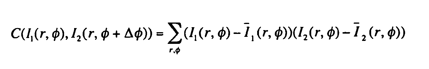

Dabei steht H für die Entropie. Diese definiert sich aus: 
Die Berechnung der Korrelation bzw. der "mutual information" entspricht dem Schritt der Merkmalsextraktion 11, 21 sowie in Teilen der Berechnung der Lageänderung 30. Bei einer Lagebestimmung mit Hilfe globaler Merkmale wird zusätzlich das Bild auf der untersten Größenskala um seinen Schwerpunkt gedreht.The calculation of the correlation or the "mutual information" corresponds to the step of the
In Fig. 4 ist der Verlauf der Maße für verschiedene Drehwinkel dargestellt. Dabei wurde das Bild mit der gröbsten Längenskala des zweiten Röntgendurchleuchtungsbildes 2 um seinen Schwerpunkt gedreht und mit dem Bild des Erststufengeräts, also dem ersten Röntgendurchleuchtungsbild 1 bezüglich seines Schwerpunktes verglichen. Die Maßanalyse auf der gröbsten Längenskala liefert verschiedene Maximalpunkte. Diese werden im nächsten Schritt dazu verwendet, um auf den höheren Ebenen die Maße genauer zu bestimmen. Dies bedeutet, dass anstelle alle Drehwinkel auf jeder Ebene durchzustimmen, nur die besten Kandidaten auf der nächsthöheren Ebene verwendet werden.In Fig. 4 the course of the dimensions for different angles of rotation is shown. In this case, the image with the coarsest length scale of the second
Am Ende dieser Analyse, die auf allen Ebenen der Skalenpyramide durchgeführt wurde, werden die Korrelationsergebnisse analysiert und der Drehwinkel des Gepäckstücks 4 bestimmt. Dabei können und werden auch noch andere Informationen mitberücksichtigt. Mit Hilfe der Momentenanalyse des Bildes wurden die Drehwinkel der beiden Röntgendurchleuchtungsbilder 1, 2 errechnet und mit dem Ergebnis des oben beschriebenen Verfahrens verglichen. Darüber hinaus wurden die Maxima der verschiedenen Maße des geflippten bzw. des ungeflippten Gepäckstücks 4 miteinander verglichen und ausgewertet. Für den Fall, dass die Analyse keinen eindeutigen Winkel bestimmen kann, werden dann gegebenenfalls weitere Winkel ausgegeben. Eine weitere Verfeinerung ist unter Verwendung lokaler Merkmale möglich (siehe unten zu Fig. 6 a-d).At the end of this analysis, which was performed on all levels of the scale pyramid, the correlation results are analyzed and the angle of rotation of the item of
Da nun die Lageänderung des Gepäckstücks 4 bekannt ist, lässt sich die neue Position der verdächtigen Region abschätzen. In dieser Region kann nun ein abschließender Scan durchgeführt werden. Die in Fig. 4 dargestellten Linien gehören zum einen zu einem nicht gekippten Koffer (line 1) und im anderen Fall zu einem gekippten Koffer (line 2).Now that the change in position of the
In Fig. 5 ist anstatt der "mutual information" der Fig. 4 die Korrelation für unterschiedliche Winkelmaße des ersten Röntgendurchleuchtungsbildes 1 mit dem zweiten Röntgendurchleuchtungsbild 2 auf der gröbsten Längenskala angegeben. Auch hier sind zwei Linien dargestellt, wobei die eine Linie (line 1) zu einem nicht geflippten Koffer und die zweite Linie (line 2) zu einem geflippten Koffer gehört.In FIG. 5, instead of the "mutual information" of FIG. 4, the correlation for different angular dimensions of the first X-ray
In den Fig. 6 a-d ist das Verfahren der Merkmalsextraktion 11, 21 mit Hilfe lokaler Merkmale dargestellt. In den Fig. 6 a und 6 c ist dasselbe Gepäckstück 4 in unterschiedlichen Lagen dargestellt. In Fig. 6 b ist ein erster Bildausschnitt 13 aus Fig. 6 a dargestellt, in dem eine Flasche zu erkennen ist. Die selbe Flasche ist in Fig. 6 d nach Durchführung des erfindungsgemäßen Verfahrens aufgefunden worden.In Figs. 6a-d, the method of
Die Lagebestimmung mittels lokaler Merkmale kann für sich allein oder als Nachbearbeitungsschritt zu einer Lagebestimmung mit Hilfe der globalen Merkmale (wie oben zu den Fig. 3 a-d ausgeführt) durchgeführt werden. Die Vorverarbeitung 10, 20 wurde hierfür vorher durchgeführt. Unter Umständen sind noch weitere Schritte notwendig, je nach dem, wie die lokalen Merkmale definiert werden. Zunächst werden aus dem ersten Röntgendurchleuchtungsbild 1 verschiedene erste Bildausschnitte 13 mit lokalen Features ermittelt. Dies kann beispielsweise durch Bestimmung von Kanten, Ecken oder Bereichen hoher Intensität erreicht werden. Darüber hinaus kann auch eine Bestimmung der Entropie der lokalen Amplitudenstatistik erfolgen. Die Amplitudenstatistik beschreibt die Wahrscheinlichkeitsdichte innerhalb des ersten Bildausschnitts 13 x ∈ [x 0,x 0 + L x ], y ∈ [y 0,y 0 + L y ] einen bestimmten Amplitudenwert ![]()

![]()
![]()
![]()
Kennzeichnend für die Amplitudenstatistik ist, dass sie keine räumlichen Informationen enthält. Sie ist daher unabhängig von der relativen Lage einzelner Objekte des ersten Bildausschnitts 13.Characteristic of the amplitude statistics is that it contains no spatial information. It is therefore independent of the relative position of individual objects of the
Analog wird im zweiten Röntgendurchleuchtungsbild 2 nach denselben oder sinnvoll erweiterten Regeln ebenfalls nach lokalen Merkmalen gesucht, was der in Fig. 1 dargestellten zweiten Merkmalsextraktion 21 entspricht. Für beide Röntgendurchleuchtungsbilder 1, 2 existiert eine Menge von Merkmalen mit ihren Koordinaten {X1, 2 (x, y)}. Im nächsten Schritt wird versucht, die verschiedenen Merkmale einander zuzuordnen. Alternativ kann auf die Suche nach Merkmale in einem Bild verzichtet werden. Dann werden die Merkmale des anderen Röntgendurchleuchtungsbildes 1, 2 im kompletten Bild gesucht.Analogously, in the second
Exemplarisch werden im Folgenden die Merkmale über ihre Amplitudenstatistiken beschrieben. Es wird dabei angenommen, dass die beiden Bildausschnitte 13, 23 der Fig. 6 b und 6 d, die sich am ähnlichsten sind, das gesuchte Merkmal enthalten. In dem hier vorgestellten Verfahren wurde als Ähnlichkeitsmaß die Differenz bezüglich der verschiedenen Momente der Amplitudenstatistik sowie die Entropie verwendet. Andere Ähnlichkeitsmaße sind beispielsweise der Wert des Faltungsintegrals der Wahrscheinlichkeitsdichten.As an example, the features of their amplitude statistics are described below. It is assumed that the two
Aus dem ersten Röntgendurchleuchtungsbild 1 des Gepäckstücks 4 (Fig. 6 a) wurde ein erster Bildausschnitt 13 (Fig. 6 b) ausgewählt. Danach wurde im zweiten Röntgendurchleuchtungsbild 2 (Fig. 6 c) ein zweiter Bildausschnitt 23 mit den gleichen Abmaßen gesucht, der dem ersten Bildausschnitt 13 in seinen statistischen Eigenschaften ähnelt. Da es sich bei dem zweiten Bildausschnitt 23 der Fig. 6 b um ein Rechteck handelt, die Lage des Gepäckstücks 4 sich allerdings zwischen der Fig. 6 a und der Fig. 6 c durch eine Drehung geändert hat, ist in Fig. 6 d die Flasche nicht vollständig abgebildet. Dieses Problem ließe sich beispielsweise dadurch umgehen, dass keine rechteckigen Bildausschnitte 13, 23 verwendet werden, sondern kreisrunde.From the first
Im Ergebnis konnte ein Teil der verschiedenen Merkmale einander zugeordnet werden. Die Paare beschreiben somit zwei Sichten des selben Merkmales. Geht man davon aus, dass lediglich das Gepäckstück 4, jedoch nicht sein Inhalt, seine Lage verändert hat, ist es möglich, die Berechnung der Lageänderung 30 des Gepäckstücks 4 anhand der neuen Koordinaten vorzunehmen.As a result, some of the different features could be assigned to each other. The pairs thus describe two views of the same feature. Assuming that only the item of
Für jedes Merkmal x i gilt, dass es die geltende Abbildungsgleichung (siehe auch Richard Hartley and Andrew Zisserman in "Multiple View Geometry in Computer Vision"; Second Edition; Cambridge University Press, March 2004) erfüllt, diese lautet: ![]()
![]()
![]()
![]()
![]()
![]()
Für die Lösung dieses mathematischen Problems existieren eine Reihe verschiedener Techniken. Ist gewährleistet, dass die Zuordnungen der Merkmale hinreichend gut ist, kann mit Hilfe eines Least-Square-Verfahrens versucht werden, die gesuchten Drehwinkel und Translationen zu bestimmen. Andernfalls kann auf sogenannte robuste Schätzverfahren zurückgegriffen werden.There are a number of different techniques for solving this mathematical problem. If it is ensured that the assignments of the features are sufficiently good, a least-square method can be used to determine the desired rotation angles and translations. Otherwise, so-called robust estimation methods can be used.
Das Prinzip der Erfindung, das anhand der Fig. 1 bis 6 ausführlich oben beschrieben wurde, kann anhand Fig. 7 wie folgt zusammengefasst werden:The principle of the invention, which has been described in detail above with reference to FIGS. 1 to 6, can be summarized with reference to FIG. 7 as follows:
Ein erstes Röntgendurchleuchtungsbild 1 eines Gepäckstücks 4 aus einem Erststufengerät (linke Seite) ist einem zweiten Röntgendurchleuchtungsbild 2 desselben Gepäckstücks 4 eines weiteren Röntgendurchleuchtungsapparats gegenübergestellt. Das Gepäckstück 4 ist hierbei sowohl gedreht als auch geflippt worden. Aufgrund des durchgeführten erfindungsgemäßen Verfahrens ist eine Zuordnung der ersten verdächtigen Region 13 (die zur Verdeutlichung als Rechteck eingezeichnet ist) zu der zweiten verdächtige Region 23 sehr gut möglich.A first X-ray
Zur starken Verringerung der Analysezeit wird in einem Zweitstufengerät lediglich noch eine Analyse der zweiten verdächtigen Region 23 durchgeführt, die in einem ersten Röntgendurchleuchtungsbild 1 in einem Erststufengerät als verdächtig eingestuft wurde. Die Koordinaten der von dem Erststufengerät ermittelten ersten verdächtigen Region 13, sowie ein Linescanbild werden dem Zweitstufengerät übermittelt. Da beide Geräte räumlich voneinander getrennt sind und das Gepäckstück 4 somit regelmäßig über verschiedene Transportsysteme vom Erststufengerät zum Zweitstufengerät gebracht wird, müssen die Koordinaten der neuen Lage des Gepäckstücks 4 angepasst werden. Hierzu ist auch das Zweitstufengerät mit einem Linescanner ausgestattet. Nach dem Scannen des zweiten Röntgendurchleuchtungsbilds 2 werden die beiden Röntgendurchleuchtungsbilder 1, 2 jeweils einer Vorverarbeitung 10, 20 mittels einer Kalibrierung unterzogen, so dass sie miteinander vergleichbar sind. Daran schließt sich jeweils eine Merkmalsextraktion 11, 21 mittels globaler und/oder lokaler Merkmale für jedes der beiden Röntgendurchleuchtungsbilder 1, 2 an. Aufgrund der aus den beiden Merkmalsextraktionen 11, 21 gewonnenen Merkmale kann mittels eines Vergleichs die Lageänderung des Objekts 4 berechnet werden. Dadurch ist es möglich, dass in dem Zweitstufengerät nur noch die zweite verdächtigen Region 23 analysiert wird und nicht mehr das gesamte Objekt 4. Das erfindungsgemäße Verfahren bewirkt somit eine hochgradige Zeitersparnis bei der Analyse des Objekts 4 ohne dass die Detektionsrate abfällt oder die Fehlalarmrate ansteigt.To greatly reduce the analysis time, in a second-stage device only an analysis of the
- 11
- Erstes RöntgendurchleuchtungsbildFirst fluoroscopic image
- 22
- Zweites RöntgendurchleuchtungsbildSecond radiographic image
- 44
- Gepäckstückpiece of baggage
- 1010
- Vorverarbeitung des ersten RöntgendurchleuchtungsbildsPre-processing of the first X-ray fluoroscopic image
- 1111
- Erste MerkmalsextraktionFirst feature extraction
- 1212
- Erste Liste der verdächtigen RegionenFirst list of suspicious regions
- 1313
- Erster Bildausschnitt bzw. erste verdächtige RegionFirst image section or first suspicious region
- 2020
- Vorverarbeitung des zweiten RöntgendurchleuchtungsbildsPre-processing of the second X-ray fluoroscopic image
- 2121
- Zweite MerkmalsextraktionSecond feature extraction
- 2222
- Zweite Liste der verdächtigen RegionenSecond list of suspicious regions
- 2323
- Zweiter Bildausschnitt bzw. zweite verdächtige RegionSecond image section or second suspicious region
- 3030
- Berechnung der LageänderungCalculation of the change in position
- 3131
- Geometrische TransformationGeometric transformation
Claims (14)
- Method for determining the change in position of an item of luggage (4) in order to examine a suspect region (13, 23) in this item of luggage (4) with the following steps:- Taking a first picture of the item of luggage (4) by means of a first examination system;- Conveying the item of luggage (4) from the first examination system to a second examination system which is physically separated from the first examination system;- Transferring the first picture of the item of luggage (4) and of coordinates of a first suspect region (13) in the item of luggage from the first examination system to the second examination system;- Taking a second picture of the item of luggage (4) by means of the second examination system;- Comparing the two pictures of the item of luggage (4) of the first and second examination systems;- Determining the change in position of the item of luggage (4) giving a first angle of rotation about the vertical axis, a second angle of rotation about the horizontal axis and a translation;- Determining the coordinates of the second suspect region (23), which corresponds to the first suspect region (13) in the first examination system, in the second examination system;- Targeted examination of the item of luggage (4) only in the area of the coordinates of the second suspect region (23) in the second examination system.
- Method according to claim 1, characterized in that in the first examination system a picture of a first fluoroscopic image (1) is taken and a first suspect region (13) in the item of luggage (4) is determined by means of a first fluoroscopy apparatus.
- Method according to claim 2, characterized in that an optical and/or geometrical preprocessing of the first and/or second fluoroscopic image (1, 2) takes place before the determination of the change in position.
- Method according to one of the previous claims, characterized in that a set of first and/or second angles of rotation are issued in the case of ambiguities.
- Method according to claim 4, characterized in that a probability value is given in each case for the first and/or second angles of rotation.
- Method according to one of the previous claims, characterized in that the change in position of the item of luggage (4) is determined using global features, in particular correlation, mutual information or radial dimensional variables.
- Method according to claim 6, characterized in that it is coupled with a scale analysis.
- Method according to claim 6 or 7, characterized in that different comparison values are used.
- Method according to one of the previous claims, characterized in that the change in position of the item of luggage (4) is determined using local features, in particular using RANSAC, robust estimation methods, Hough transformations or least-square methods.
- Method according to claim 9, characterized in that a coupling with a scale analysis is carried out.
- Method according to claim 9 or 10, characterized in that the determination of the change in position using local features takes place on different linear scales.
- Method according to claim 11, characterized in that the local features are chosen according to the linear scale.
- Method according to one of the previous claims, characterized in that a comparison of the results of the analysis using the global features with the results of the analysis using the local features takes place.
- Method according to one of the previous claims, characterized in that only the local features are used which do not contradict the analysis using the global features.
Applications Claiming Priority (2)
| Application Number | Priority Date | Filing Date | Title |
|---|---|---|---|
| DE10346269 | 2003-10-06 | ||
| DE10346269 | 2003-10-06 |
Publications (2)
| Publication Number | Publication Date |
|---|---|
| EP1522878A1 EP1522878A1 (en) | 2005-04-13 |
| EP1522878B1 true EP1522878B1 (en) | 2006-08-09 |
Family
ID=34306278
Family Applications (1)
| Application Number | Title | Priority Date | Filing Date |
|---|---|---|---|
| EP04023811A Expired - Lifetime EP1522878B1 (en) | 2003-10-06 | 2004-10-06 | Method for determining the displacement of luggage in order to scan a suspicious region in the luggage |
Country Status (5)
| Country | Link |
|---|---|
| US (2) | US7406192B2 (en) |
| EP (1) | EP1522878B1 (en) |
| AT (1) | ATE336015T1 (en) |
| DE (1) | DE502004001146D1 (en) |
| ES (1) | ES2270254T3 (en) |
Families Citing this family (17)
| Publication number | Priority date | Publication date | Assignee | Title |
|---|---|---|---|---|
| US7963695B2 (en) | 2002-07-23 | 2011-06-21 | Rapiscan Systems, Inc. | Rotatable boom cargo scanning system |
| DE102004049227B4 (en) * | 2004-10-08 | 2007-03-01 | Yxlon International Security Gmbh | Method for determining the change in position of an object in a piece of luggage |
| DE102005044135B4 (en) * | 2005-09-15 | 2007-07-12 | Yxlon International Security Gmbh | Method for determining the change in position of an object within a container by means of X-rays |
| US7548606B2 (en) | 2006-08-31 | 2009-06-16 | Ge Homeland Protection, Inc. | System and method for integrating explosive detection systems |
| US9310323B2 (en) | 2009-05-16 | 2016-04-12 | Rapiscan Systems, Inc. | Systems and methods for high-Z threat alarm resolution |
| EP2430396B1 (en) | 2009-05-16 | 2020-01-15 | Rapiscan Systems, Inc. | Systems and methods for automated, rapid detection of high-atomic-number materials |
| DE102009060057A1 (en) * | 2009-12-22 | 2011-06-30 | Siemens Aktiengesellschaft, 80333 | Method for identifying lost or unassignable luggage |
| CN102884422B (en) * | 2010-02-25 | 2016-09-28 | 拉皮斯坎系统股份有限公司 | In order to determine the atomic number of material, high-energy X-rays inspection system and method based on spectroscopy |
| US9224573B2 (en) | 2011-06-09 | 2015-12-29 | Rapiscan Systems, Inc. | System and method for X-ray source weight reduction |
| US9218933B2 (en) | 2011-06-09 | 2015-12-22 | Rapidscan Systems, Inc. | Low-dose radiographic imaging system |
| US9158029B2 (en) | 2013-06-14 | 2015-10-13 | Morpho Detection, Llc | Multi-stage security screening system and smart communication system |
| US9557427B2 (en) | 2014-01-08 | 2017-01-31 | Rapiscan Systems, Inc. | Thin gap chamber neutron detectors |
| DE102014205447A1 (en) | 2014-03-24 | 2015-09-24 | Smiths Heimann Gmbh | Detection of objects in an object |
| JP6431302B2 (en) * | 2014-06-30 | 2018-11-28 | キヤノン株式会社 | Image processing apparatus, image processing method, and program |
| CN106560839B (en) * | 2015-09-30 | 2019-08-27 | 同方威视技术股份有限公司 | The detection method and device of bottle |
| JP7115376B2 (en) * | 2019-03-18 | 2022-08-09 | 日本電信電話株式会社 | Rotation state estimation device, method and program |
| EP4562413A1 (en) | 2022-07-26 | 2025-06-04 | Rapiscan Holdings, Inc. | Methods and systems for performing on-the-fly automatic calibration adjustments of x-ray inspection systems |
Family Cites Families (24)
| Publication number | Priority date | Publication date | Assignee | Title |
|---|---|---|---|---|
| JPS6367552A (en) | 1986-09-10 | 1988-03-26 | Hitachi Medical Corp | X-ray inspection instrument |
| FR2641867B1 (en) * | 1989-01-13 | 1991-03-08 | Commissariat Energie Atomique | METHOD AND DEVICE FOR DETECTION OF SUBSTANCES AND PARTICULARLY EXPLOSIVES, BY NEUTRONIC IRRADIATION THEREOF |
| US5319547A (en) * | 1990-08-10 | 1994-06-07 | Vivid Technologies, Inc. | Device and method for inspection of baggage and other objects |
| US5367552A (en) * | 1991-10-03 | 1994-11-22 | In Vision Technologies, Inc. | Automatic concealed object detection system having a pre-scan stage |
| US5182764A (en) * | 1991-10-03 | 1993-01-26 | Invision Technologies, Inc. | Automatic concealed object detection system having a pre-scan stage |
| DE4206187C1 (en) * | 1992-02-28 | 1993-11-11 | Fedag Romanshorn Fa | Suction cleaning device |
| US5692029A (en) * | 1993-01-15 | 1997-11-25 | Technology International Incorporated | Detection of concealed explosives and contraband |
| FR2705786B1 (en) * | 1993-05-28 | 1995-08-25 | Schlumberger Ind Sa | Method and device for recognizing certain materials in the composition of an object. |
| DE4406956C2 (en) * | 1994-03-03 | 1997-01-30 | Heimann Systems Gmbh & Co | Method for detecting illegal baggage items |
| DE4420618A1 (en) | 1994-06-13 | 1995-12-14 | Heilander Und Goslau Sondermas | Device for automatic mounting of parts along contour of construction component, e.g. car roof |
| US5642393A (en) | 1995-09-26 | 1997-06-24 | Vivid Technologies, Inc. | Detecting contraband by employing interactive multiprobe tomography |
| EP0825457A3 (en) * | 1996-08-19 | 2002-02-13 | Analogic Corporation | Multiple angle pre-screening tomographic systems and methods |
| AU5929198A (en) | 1997-01-24 | 1998-08-18 | Quanta Vision, Inc. | Inspection equipment using small-angle topography in determining an object's internal structure and composition |
| DE19756697A1 (en) | 1997-12-19 | 1999-07-01 | Manfred Dr Ing Pfeiler | System for producing X-ray tomograms of linearly moving goods |
| DE19812055C2 (en) | 1998-03-19 | 2002-08-08 | Heimann Systems Gmbh & Co | Image processing for material detection using X-rays |
| DE19855250A1 (en) * | 1998-11-30 | 2000-06-08 | Heimann Systems Gmbh & Co | Process for optimizing an X-ray image |
| GB9909163D0 (en) * | 1999-04-21 | 1999-06-16 | Image Scan Holdings Plc | Automatic defect detection |
| DE19954662B4 (en) | 1999-11-13 | 2004-06-03 | Smiths Heimann Gmbh | Apparatus and method for detecting unauthorized luggage items |
| IL158189A0 (en) * | 2001-04-03 | 2004-03-28 | L 3 Comm Security & Detection | A remote baggage screening system, software and method |
| DE10139672A1 (en) | 2001-08-11 | 2003-03-06 | Heimann Systems Gmbh & Co | Method and installation for inspecting an object, in particular a piece of luggage |
| DE10149254B4 (en) * | 2001-10-05 | 2006-04-20 | Smiths Heimann Gmbh | Method and device for detecting a specific material in an object by means of electromagnetic radiation |
| WO2003065077A2 (en) | 2002-01-30 | 2003-08-07 | Rutgers, The State University | Combinatorial contraband detection using energy dispersive x-ray diffraction |
| US20050128304A1 (en) * | 2002-02-06 | 2005-06-16 | Manasseh Frederick M. | System and method for traveler interactions management |
| EP1597611A1 (en) * | 2003-02-13 | 2005-11-23 | Philips Intellectual Property & Standards GmbH | Method and device for examining an object |
-
2004
- 2004-10-06 EP EP04023811A patent/EP1522878B1/en not_active Expired - Lifetime
- 2004-10-06 DE DE502004001146T patent/DE502004001146D1/en not_active Expired - Lifetime
- 2004-10-06 ES ES04023811T patent/ES2270254T3/en not_active Expired - Lifetime
- 2004-10-06 US US10/960,348 patent/US7406192B2/en not_active Expired - Fee Related
- 2004-10-06 AT AT04023811T patent/ATE336015T1/en not_active IP Right Cessation
-
2008
- 2008-07-03 US US12/167,718 patent/US7660457B2/en not_active Expired - Fee Related
Also Published As
| Publication number | Publication date |
|---|---|
| US20080310589A1 (en) | 2008-12-18 |
| ATE336015T1 (en) | 2006-09-15 |
| ES2270254T3 (en) | 2007-04-01 |
| DE502004001146D1 (en) | 2006-09-21 |
| US7406192B2 (en) | 2008-07-29 |
| EP1522878A1 (en) | 2005-04-13 |
| US7660457B2 (en) | 2010-02-09 |
| US20050123217A1 (en) | 2005-06-09 |
Similar Documents
| Publication | Publication Date | Title |
|---|---|---|
| EP1522878B1 (en) | Method for determining the displacement of luggage in order to scan a suspicious region in the luggage | |
| DE69630935T2 (en) | Image processing method and apparatus for automatically detecting areas of a predetermined type of cancer in an intensity image | |
| DE69027616T2 (en) | Device and method for determining contours and lines | |
| DE69624614T2 (en) | Stereo matching and inequality measurement method | |
| DE69811049T2 (en) | ELECTRONIC IMAGE PROCESSING DEVICE FOR DETECTING DIMENSIONAL CHANGES | |
| EP3123208B1 (en) | Detection of items in a container | |
| DE3840257C2 (en) | Procedure for the automatic assessment of differences between normal and abnormal lungs | |
| DE69623642T2 (en) | VECTOR CORRELATION SYSTEM FOR AUTOMATICALLY FINDING PATTERNS IN AN IMAGE | |
| DE69427567T2 (en) | Method for finding a histogram area of interest for improved gray-scale reproduction of X-ray images | |
| DE112008004057T5 (en) | Detect hidden threats | |
| DE60307967T2 (en) | IMAGE PROCESSING FOR THE STUDY OF THE APPEARANCE | |
| DE102009051826A1 (en) | Method for comparing the similarity of 3D pictorial objects | |
| EP3734260B1 (en) | Method and apparatus for x-ray inspection of products, in particular food products | |
| DE102004057026A1 (en) | Acquisition of temporal image changes and presentation method and apparatus | |
| DE202009013865U1 (en) | Concept for selecting an optimized evaluation feature subset for inspection of free-form surfaces and concept for inspecting a free-form surface | |
| EP2584493A2 (en) | Method for distinguishing between a real face and a two-dimensional image of the face in a biometric recording process | |
| EP1037166A1 (en) | Method for the detection of contours in an X-Ray image | |
| DE10054814A1 (en) | Images registration method e.g. for medical image matching, magnetic resonance tomography, involves transforming discrete images into registered images | |
| DE102007026804A1 (en) | Method for processing radiological images for detecting radiological abnormalities | |
| DE102005037367B3 (en) | Method for an X-ray device | |
| DE102004049227B4 (en) | Method for determining the change in position of an object in a piece of luggage | |
| DE102016011378A1 (en) | Method for self-localization of a vehicle | |
| AT11770U1 (en) | METHOD FOR SELECTING AN OPTIMIZED EVALUATION TEMPERATURE FOR CONTROLLING A FREE-FORM SURFACE AND METHOD FOR CHECKING A FREE-FORM SURFACE | |
| DE102018221617A1 (en) | Method for determining a relative movement using a digital image sequence | |
| DE102019123479B3 (en) | Analysis and quality control of food |
Legal Events
| Date | Code | Title | Description |
|---|---|---|---|
| PUAI | Public reference made under article 153(3) epc to a published international application that has entered the european phase |
Free format text: ORIGINAL CODE: 0009012 |
|
| AK | Designated contracting states |
Kind code of ref document: A1 Designated state(s): AT BE BG CH CY CZ DE DK EE ES FI FR GB GR HU IE IT LI LU MC NL PL PT RO SE SI SK TR |
|
| AX | Request for extension of the european patent |
Extension state: AL HR LT LV MK |
|
| 17P | Request for examination filed |
Effective date: 20051013 |
|
| AKX | Designation fees paid |
Designated state(s): AT BE BG CH CY CZ DE DK EE ES FI FR GB GR HU IE IT LI LU MC NL PL PT RO SE SI SK TR |
|
| GRAP | Despatch of communication of intention to grant a patent |
Free format text: ORIGINAL CODE: EPIDOSNIGR1 |
|
| GRAS | Grant fee paid |
Free format text: ORIGINAL CODE: EPIDOSNIGR3 |
|
| GRAA | (expected) grant |
Free format text: ORIGINAL CODE: 0009210 |
|
| AK | Designated contracting states |
Kind code of ref document: B1 Designated state(s): AT BE BG CH CY CZ DE DK EE ES FI FR GB GR HU IE IT LI LU MC NL PL PT RO SE SI SK TR |
|
| PG25 | Lapsed in a contracting state [announced via postgrant information from national office to epo] |
Ref country code: IT Free format text: LAPSE BECAUSE OF FAILURE TO SUBMIT A TRANSLATION OF THE DESCRIPTION OR TO PAY THE FEE WITHIN THE PRESCRIBED TIME-LIMIT;WARNING: LAPSES OF ITALIAN PATENTS WITH EFFECTIVE DATE BEFORE 2007 MAY HAVE OCCURRED AT ANY TIME BEFORE 2007. THE CORRECT EFFECTIVE DATE MAY BE DIFFERENT FROM THE ONE RECORDED. Effective date: 20060809 Ref country code: SK Free format text: LAPSE BECAUSE OF FAILURE TO SUBMIT A TRANSLATION OF THE DESCRIPTION OR TO PAY THE FEE WITHIN THE PRESCRIBED TIME-LIMIT Effective date: 20060809 Ref country code: FI Free format text: LAPSE BECAUSE OF FAILURE TO SUBMIT A TRANSLATION OF THE DESCRIPTION OR TO PAY THE FEE WITHIN THE PRESCRIBED TIME-LIMIT Effective date: 20060809 Ref country code: SI Free format text: LAPSE BECAUSE OF FAILURE TO SUBMIT A TRANSLATION OF THE DESCRIPTION OR TO PAY THE FEE WITHIN THE PRESCRIBED TIME-LIMIT Effective date: 20060809 Ref country code: PL Free format text: LAPSE BECAUSE OF FAILURE TO SUBMIT A TRANSLATION OF THE DESCRIPTION OR TO PAY THE FEE WITHIN THE PRESCRIBED TIME-LIMIT Effective date: 20060809 Ref country code: RO Free format text: LAPSE BECAUSE OF FAILURE TO SUBMIT A TRANSLATION OF THE DESCRIPTION OR TO PAY THE FEE WITHIN THE PRESCRIBED TIME-LIMIT Effective date: 20060809 Ref country code: IE Free format text: LAPSE BECAUSE OF FAILURE TO SUBMIT A TRANSLATION OF THE DESCRIPTION OR TO PAY THE FEE WITHIN THE PRESCRIBED TIME-LIMIT Effective date: 20060809 Ref country code: CZ Free format text: LAPSE BECAUSE OF FAILURE TO SUBMIT A TRANSLATION OF THE DESCRIPTION OR TO PAY THE FEE WITHIN THE PRESCRIBED TIME-LIMIT Effective date: 20060809 Ref country code: NL Free format text: LAPSE BECAUSE OF FAILURE TO SUBMIT A TRANSLATION OF THE DESCRIPTION OR TO PAY THE FEE WITHIN THE PRESCRIBED TIME-LIMIT Effective date: 20060809 |
|
| REG | Reference to a national code |
Ref country code: GB Ref legal event code: FG4D Free format text: NOT ENGLISH |
|
| REG | Reference to a national code |
Ref country code: CH Ref legal event code: EP |
|
| REG | Reference to a national code |
Ref country code: IE Ref legal event code: FG4D Free format text: LANGUAGE OF EP DOCUMENT: GERMAN |
|
| REF | Corresponds to: |
Ref document number: 502004001146 Country of ref document: DE Date of ref document: 20060921 Kind code of ref document: P |
|
| GBT | Gb: translation of ep patent filed (gb section 77(6)(a)/1977) |
Effective date: 20061004 |
|
| PG25 | Lapsed in a contracting state [announced via postgrant information from national office to epo] |
Ref country code: MC Free format text: LAPSE BECAUSE OF NON-PAYMENT OF DUE FEES Effective date: 20061031 |
|
| PG25 | Lapsed in a contracting state [announced via postgrant information from national office to epo] |
Ref country code: DK Free format text: LAPSE BECAUSE OF FAILURE TO SUBMIT A TRANSLATION OF THE DESCRIPTION OR TO PAY THE FEE WITHIN THE PRESCRIBED TIME-LIMIT Effective date: 20061109 Ref country code: SE Free format text: LAPSE BECAUSE OF FAILURE TO SUBMIT A TRANSLATION OF THE DESCRIPTION OR TO PAY THE FEE WITHIN THE PRESCRIBED TIME-LIMIT Effective date: 20061109 Ref country code: BG Free format text: LAPSE BECAUSE OF FAILURE TO SUBMIT A TRANSLATION OF THE DESCRIPTION OR TO PAY THE FEE WITHIN THE PRESCRIBED TIME-LIMIT Effective date: 20061109 |
|
| PG25 | Lapsed in a contracting state [announced via postgrant information from national office to epo] |
Ref country code: PT Free format text: LAPSE BECAUSE OF FAILURE TO SUBMIT A TRANSLATION OF THE DESCRIPTION OR TO PAY THE FEE WITHIN THE PRESCRIBED TIME-LIMIT Effective date: 20070109 |
|
| NLV1 | Nl: lapsed or annulled due to failure to fulfill the requirements of art. 29p and 29m of the patents act | ||
| ET | Fr: translation filed | ||
| REG | Reference to a national code |
Ref country code: IE Ref legal event code: FD4D |
|
| REG | Reference to a national code |
Ref country code: ES Ref legal event code: FG2A Ref document number: 2270254 Country of ref document: ES Kind code of ref document: T3 |
|
| PLBE | No opposition filed within time limit |
Free format text: ORIGINAL CODE: 0009261 |
|
| STAA | Information on the status of an ep patent application or granted ep patent |
Free format text: STATUS: NO OPPOSITION FILED WITHIN TIME LIMIT |
|
| RAP2 | Party data changed (patent owner data changed or rights of a patent transferred) |
Owner name: GE HOMELAND PROTECTION, INC. |
|
| 26N | No opposition filed |
Effective date: 20070510 |
|
| REG | Reference to a national code |
Ref country code: GB Ref legal event code: 732E |
|
| REG | Reference to a national code |
Ref country code: GB Ref legal event code: 732E |
|
| REG | Reference to a national code |
Ref country code: FR Ref legal event code: TP Ref country code: FR Ref legal event code: CD |
|
| BERE | Be: lapsed |
Owner name: YXLON INTERNATIONAL SECURITY G.M.B.H. Effective date: 20061031 |
|
| PG25 | Lapsed in a contracting state [announced via postgrant information from national office to epo] |
Ref country code: AT Free format text: LAPSE BECAUSE OF NON-PAYMENT OF DUE FEES Effective date: 20061006 |
|
| PG25 | Lapsed in a contracting state [announced via postgrant information from national office to epo] |
Ref country code: GR Free format text: LAPSE BECAUSE OF FAILURE TO SUBMIT A TRANSLATION OF THE DESCRIPTION OR TO PAY THE FEE WITHIN THE PRESCRIBED TIME-LIMIT Effective date: 20061110 |
|
| PG25 | Lapsed in a contracting state [announced via postgrant information from national office to epo] |
Ref country code: EE Free format text: LAPSE BECAUSE OF FAILURE TO SUBMIT A TRANSLATION OF THE DESCRIPTION OR TO PAY THE FEE WITHIN THE PRESCRIBED TIME-LIMIT Effective date: 20060809 |
|
| PG25 | Lapsed in a contracting state [announced via postgrant information from national office to epo] |
Ref country code: LU Free format text: LAPSE BECAUSE OF NON-PAYMENT OF DUE FEES Effective date: 20061006 Ref country code: HU Free format text: LAPSE BECAUSE OF FAILURE TO SUBMIT A TRANSLATION OF THE DESCRIPTION OR TO PAY THE FEE WITHIN THE PRESCRIBED TIME-LIMIT Effective date: 20070210 Ref country code: TR Free format text: LAPSE BECAUSE OF FAILURE TO SUBMIT A TRANSLATION OF THE DESCRIPTION OR TO PAY THE FEE WITHIN THE PRESCRIBED TIME-LIMIT Effective date: 20060809 |
|
| PG25 | Lapsed in a contracting state [announced via postgrant information from national office to epo] |
Ref country code: CY Free format text: LAPSE BECAUSE OF FAILURE TO SUBMIT A TRANSLATION OF THE DESCRIPTION OR TO PAY THE FEE WITHIN THE PRESCRIBED TIME-LIMIT Effective date: 20060809 |
|
| REG | Reference to a national code |
Ref country code: CH Ref legal event code: PL |
|
| PG25 | Lapsed in a contracting state [announced via postgrant information from national office to epo] |
Ref country code: BE Free format text: LAPSE BECAUSE OF FAILURE TO SUBMIT A TRANSLATION OF THE DESCRIPTION OR TO PAY THE FEE WITHIN THE PRESCRIBED TIME-LIMIT Effective date: 20061031 |
|
| PG25 | Lapsed in a contracting state [announced via postgrant information from national office to epo] |
Ref country code: LI Free format text: LAPSE BECAUSE OF NON-PAYMENT OF DUE FEES Effective date: 20081031 Ref country code: CH Free format text: LAPSE BECAUSE OF NON-PAYMENT OF DUE FEES Effective date: 20081031 |
|
| PGFP | Annual fee paid to national office [announced via postgrant information from national office to epo] |
Ref country code: DE Payment date: 20091028 Year of fee payment: 6 Ref country code: ES Payment date: 20091026 Year of fee payment: 6 |
|
| PGFP | Annual fee paid to national office [announced via postgrant information from national office to epo] |
Ref country code: FR Payment date: 20091029 Year of fee payment: 6 Ref country code: GB Payment date: 20091026 Year of fee payment: 6 |
|
| GBPC | Gb: european patent ceased through non-payment of renewal fee |
Effective date: 20101006 |
|
| PG25 | Lapsed in a contracting state [announced via postgrant information from national office to epo] |
Ref country code: FR Free format text: LAPSE BECAUSE OF NON-PAYMENT OF DUE FEES Effective date: 20101102 |
|
| REG | Reference to a national code |
Ref country code: FR Ref legal event code: ST Effective date: 20110630 |
|
| PG25 | Lapsed in a contracting state [announced via postgrant information from national office to epo] |
Ref country code: GB Free format text: LAPSE BECAUSE OF NON-PAYMENT OF DUE FEES Effective date: 20101006 |
|
| REG | Reference to a national code |
Ref country code: DE Ref legal event code: R119 Ref document number: 502004001146 Country of ref document: DE Effective date: 20110502 |
|
| REG | Reference to a national code |
Ref country code: ES Ref legal event code: FD2A Effective date: 20111118 |
|
| PG25 | Lapsed in a contracting state [announced via postgrant information from national office to epo] |
Ref country code: ES Free format text: LAPSE BECAUSE OF NON-PAYMENT OF DUE FEES Effective date: 20101007 |
|
| PG25 | Lapsed in a contracting state [announced via postgrant information from national office to epo] |
Ref country code: DE Free format text: LAPSE BECAUSE OF NON-PAYMENT OF DUE FEES Effective date: 20110502 |
|
| P01 | Opt-out of the competence of the unified patent court (upc) registered |
Effective date: 20230528 |