EP1522674A2 - Expandable Tubing - Google Patents
Expandable Tubing Download PDFInfo
- Publication number
- EP1522674A2 EP1522674A2 EP05100137A EP05100137A EP1522674A2 EP 1522674 A2 EP1522674 A2 EP 1522674A2 EP 05100137 A EP05100137 A EP 05100137A EP 05100137 A EP05100137 A EP 05100137A EP 1522674 A2 EP1522674 A2 EP 1522674A2
- Authority
- EP
- European Patent Office
- Prior art keywords
- tubing
- structures
- tubular structures
- wall
- expandable
- Prior art date
- Legal status (The legal status is an assumption and is not a legal conclusion. Google has not performed a legal analysis and makes no representation as to the accuracy of the status listed.)
- Granted
Links
Images
Classifications
-
- E—FIXED CONSTRUCTIONS
- E21—EARTH OR ROCK DRILLING; MINING
- E21B—EARTH OR ROCK DRILLING; OBTAINING OIL, GAS, WATER, SOLUBLE OR MELTABLE MATERIALS OR A SLURRY OF MINERALS FROM WELLS
- E21B43/00—Methods or apparatus for obtaining oil, gas, water, soluble or meltable materials or a slurry of minerals from wells
- E21B43/02—Subsoil filtering
- E21B43/10—Setting of casings, screens, liners or the like in wells
- E21B43/103—Setting of casings, screens, liners or the like in wells of expandable casings, screens, liners, or the like
- E21B43/108—Expandable screens or perforated liners
-
- E—FIXED CONSTRUCTIONS
- E21—EARTH OR ROCK DRILLING; MINING
- E21B—EARTH OR ROCK DRILLING; OBTAINING OIL, GAS, WATER, SOLUBLE OR MELTABLE MATERIALS OR A SLURRY OF MINERALS FROM WELLS
- E21B43/00—Methods or apparatus for obtaining oil, gas, water, soluble or meltable materials or a slurry of minerals from wells
- E21B43/02—Subsoil filtering
- E21B43/08—Screens or liners
-
- E—FIXED CONSTRUCTIONS
- E21—EARTH OR ROCK DRILLING; MINING
- E21B—EARTH OR ROCK DRILLING; OBTAINING OIL, GAS, WATER, SOLUBLE OR MELTABLE MATERIALS OR A SLURRY OF MINERALS FROM WELLS
- E21B43/00—Methods or apparatus for obtaining oil, gas, water, soluble or meltable materials or a slurry of minerals from wells
- E21B43/02—Subsoil filtering
- E21B43/08—Screens or liners
- E21B43/082—Screens comprising porous materials, e.g. prepacked screens
-
- E—FIXED CONSTRUCTIONS
- E21—EARTH OR ROCK DRILLING; MINING
- E21B—EARTH OR ROCK DRILLING; OBTAINING OIL, GAS, WATER, SOLUBLE OR MELTABLE MATERIALS OR A SLURRY OF MINERALS FROM WELLS
- E21B43/00—Methods or apparatus for obtaining oil, gas, water, soluble or meltable materials or a slurry of minerals from wells
- E21B43/02—Subsoil filtering
- E21B43/08—Screens or liners
- E21B43/084—Screens comprising woven materials, e.g. mesh or cloth
-
- E—FIXED CONSTRUCTIONS
- E21—EARTH OR ROCK DRILLING; MINING
- E21B—EARTH OR ROCK DRILLING; OBTAINING OIL, GAS, WATER, SOLUBLE OR MELTABLE MATERIALS OR A SLURRY OF MINERALS FROM WELLS
- E21B43/00—Methods or apparatus for obtaining oil, gas, water, soluble or meltable materials or a slurry of minerals from wells
- E21B43/02—Subsoil filtering
- E21B43/10—Setting of casings, screens, liners or the like in wells
- E21B43/103—Setting of casings, screens, liners or the like in wells of expandable casings, screens, liners, or the like
Definitions
- This invention relates to a downhole apparatus, and in particular but not exclusively to forms of expandable tubing and to forms of expandable filters and filter supports.
- W093/25800 (Shell Internationale Research Maatschappij B.V.) describes a method of completing an uncased section of a borehole.
- a slotted liner provided with overlapping longitudinal slots is fixed in the borehole and a tapering expansion mandrel is pushed or pulled through the liner.
- the liner is expanded by the mandrel to support the adjacent borehole wall.
- W097/17524 (Shell Internationale Research Maatschappij B.V.) describes a deformable well screen and method for its installation utilising two sections of concentric slotted tubing, such as described in WO 93/25800, with a series of circumferentially scaled filter segments therebetween.
- the screen is expanded by pushing or pulling an expansion mandrel through the screen.
- the expansion mechanism of these arrangements is such that there is an axial retraction of the tubing on radial expansion. This not only creates difficulties in accurately locating and securing the ends of the tubing in a bore relative to adjacent tubing sections, but also may result in undesirable relative axial movement between the tubing and other elements mounted thereon, such as filter segments. Further, in such a filter arrangement, the radial expansion forces which must be applied to the outer section of expandable tubing are transferred via the filter medium or media located between the tubing sections; this limits the range of media which may be utilised in such arrangements to filter materials and configurations which will withstand significant compressive forces, in addition to the significant shear forces which the filter material will experience during expansion of the tubing sections.
- expandable tubing having a tubing wall comprising a plurality of longitudinally extending deformable tubular structures, said tubular structures being arranged in side-by-side configuration to define said tubing wall and at least some of the structures having porous walls of sintered ductile material such that a fluid may flow through the structures and through the tubing wall.
- expandable tubing having a tubing wall comprising a plurality of deformable tubular structures, at least some of the structures having walls of porous material initially filled by another removable material to create an initially impermeable structure, such that upon removal of said removable material fluid may flow through the structures and thus through the tubular wall.
- expandable downhole tubing having a tubing wall comprising a plurality of longitudinally extending deformable tubular structures, said tubular structures being arranged in side-by-side configuration to define said tubing wall and said deformable tubular structures being retained between two expandable sleeves.
- expandable downhole tubing having a tubing wall comprising a plurality of longitudinally extending deformable tubular structures, said tubular structures being arranged in side-by-side configuration to define said tubing wall and said deformable tubular structures being defined by a plurality of corrugated members.
- At least some of the structures may have permeable walls such that fluid may flow through the structures and thus through the tubing wall.
- expandable downhole tubing having a tubing wall comprising a plurality of longitudinally extending deformable tubular structures, said tubular structures being arranged in side-by-side configuration to define said tubing wall and said deformable tubular structures having discontinuities therein.
- At least some of the structures may have permeable walls such that fluid may flow through the structures and thus through the tubing wall.
- the tubular structures may be substantially C-shaped.
- Deformable tubular structures forming the wall of the tubing facilitate expansion of the tubing, and the tubular structures potentially serve as filter elements. Also, the use of the tubular structures to accommodate or facilitate expansion assists in avoiding the longitudinal contraction which tends to occur on radial expansion of tubing defining overlapping longitudinally extending slots.
- the tubular structures may extend longitudinally, helically, or in be positioned in any appropriate orientation.
- a substantially axial orientation may offer more straightforward assembly and resistance to bending, however for other applications a helical arrangement may offer greater flexibility and resistance to radial compressive forces.
- the tubular structures may be of any material, structure or form which provides the desired degree of deformability, permeability and the desired degree of structural strength.
- the tubular structures are of sintered ductile metal, while in other embodiments drilled or slotted tubes may be utilised. If sintered metal, or some other porous material of similar structure, is utilised to form the tubular structures, the pores of the material may be initially filled or occupied by another material to create an impermeable structure. This filling material may be subsequently removed, for example by application of an appropriate solvent, which may be produced fluid, or exposure to elevated temperature as experienced in deeper bores.
- the tubular structures may be connected to one another by any appropriate method, for example metal structures may be welded or brazed to one another, or the structures may be retained between two expandable sleeves or tubes.
- the tubular structures may be defined by appropriately shaped sheets or elements, or unitary structures, for example two corrugated sheets or tubes which have been welded or otherwise secured together, or by extruding or other wise forming the tubing wall in a form which incorporates tubular structures.
- These embodiments may form other aspects of the invention, in which the tubular structures are impermeable, that is fluid is prevented from flowing through the tubing wall, in one or both of the unexpanded and expanded configurations.
- the tubular structures may feature substantially continuous walls, or may have discontinuities therein, for example the tubular structures may be substantially C-shaped.
- the aperture or pore size defined by the tubular structures may be selected as appropriate, depending on the intended application of the tubing: the tubing may provide a relatively coarse filter, for preventing passage of relatively large solids, or may be such that passage of liquid or very fine solids is prevented or restricted, and only passage of gas is permitted, by use of a tubular structure-lining material such as an expanded PTFE, as produced under the Gore-Tex trademark by W.L. Gore & Associates.
- a tubular structure-lining material such as an expanded PTFE, as produced under the Gore-Tex trademark by W.L. Gore & Associates.
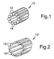
- Figures 1 and 2 of the drawings illustrate a form of expandable tubing 10, in accordance with an aspect of the present invention, and which may be utilised as or as part of a sand screen or other downhole filter arrangement.
- the tubing will be run into a bore in the "unexpanded" form as illustrated in Figure 1, anchored in the bore, and then expanded to the larger diameter expanded form as illustrated in Figure 2, with a degree of expansion in excess of 30% being achievable.
- the tubing wall 12 comprises a plurality of axially extending tubular structures in the form of small diameter tubes 14 formed of sintered metal.
- the tubes 14 provide a porous sand filtering media.
- Expansion of the tubing 10 is primarily accommodated by a flattening of the tubes 14, and the expanded tubing is shown in Figure 2 of the drawings.
- This expansion may be achieved by means of a conventional expanding cone or mandrel, which is pushed or pulled through the tubing 10.
- a conventional expanding cone or mandrel which is pushed or pulled through the tubing 10.
- pore size variation may be predicted to some extent, and in any event it is difficult to form a porous sintered metal product with closely controlled pore size.
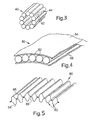
- FIG. 3 illustrates a similar form of expandable tubing 40 to that shown in Figure 1, except that the pores 42 of the material forming the tube walls are initially filled by another removable material 44 thus (temporarily) creating an impermeable structure.
- This filling material 44 may be subsequently dissolved, or removed by exposure to elevated temperatures.
- Figure 4 illustrates a further alternative embodiment of the present invention in which the tubular structures 52 are retained between two expandable sleeves 54, 55.
- Figure 5 illustrates a wall section 60 of tubing 60 of a further embodiment of the present invention wherein the tubular structures 62 are defined by inner and outer corrugated sheets 64, 66. These sheets 64, 66 are welded together at 68.
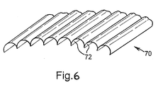
- FIG. 6 shows a wall section of tubing 70 of another embodiment of the invention, which tubing features an alternative form of tubular structures 72 to define the bounding walls of the expandable tubing 70.
- the tubular structures 72 do not have continuous walls, being substantially C-shaped.
Landscapes
- Geology (AREA)
- Life Sciences & Earth Sciences (AREA)
- Engineering & Computer Science (AREA)
- Mining & Mineral Resources (AREA)
- Environmental & Geological Engineering (AREA)
- Fluid Mechanics (AREA)
- Physics & Mathematics (AREA)
- General Life Sciences & Earth Sciences (AREA)
- Geochemistry & Mineralogy (AREA)
- Chemical & Material Sciences (AREA)
- Dispersion Chemistry (AREA)
- Filtering Materials (AREA)
- Rigid Pipes And Flexible Pipes (AREA)
- Separation Using Semi-Permeable Membranes (AREA)
- Pipe Accessories (AREA)
Abstract
Description
Claims (8)
- Expandable tubing having a tubing wall comprising a plurality of longitudinally extending deformable tubular structures, said tubular structures being arranged in side-by-side configuration to define said tubing wall and at least some of the structures having porous walls of sintered ductile material such that fluid may flow through the structures and through the tubing wall.
- Expandable tubing having a tubing wall comprising a plurality of deformable tubular structures, at least some of the structures having walls of porous material initially filled by another removable material to create an initially impermeable structure, such that upon removal of said removable material fluid may flow through the structures and thus through the tubular wall.
- Expandable downhole tubing having a tubing wall comprising a plurality of longitudinally extending deformable tubular structures, said tubular structures being arranged in side-by-side configuration to define said tubing wall and said deformable tubular structures being retained between two expandable sleeves.
- Expandable downhole tubing having a tubing wall comprising a plurality of longitudinally extending deformable tubular structures, said tubular structures being arranged in side-by-side configuration to define said tubing wall and said deformable tubular structures being defined by a plurality of corrugated members.
- The tubing of claim 4, wherein at least some of the structures have permeable walls such that fluid may flow through the structures and thus through the tubing wall.
- Expandable downhole tubing having a tubing wall comprising a plurality of longitudinally extending deformable tubular structures, said tubular structures being arranged in side-by-side configuration to define said tubing wall and said deformable tubular structures having discontinuities therein.
- The tubing of claim 6, wherein at least some of the structures have permeable walls such that fluid may flow through the structures and thus through the tubing wall.
- The tubing of claim 6 or 7, wherein the tubular structures are substantially C-shaped.
Applications Claiming Priority (3)
| Application Number | Priority Date | Filing Date | Title |
|---|---|---|---|
| GB9921557 | 1999-09-14 | ||
| GBGB9921557.6A GB9921557D0 (en) | 1999-09-14 | 1999-09-14 | Downhole apparatus |
| EP00958903A EP1212513B1 (en) | 1999-09-14 | 2000-09-14 | Expandable tubing |
Related Parent Applications (2)
| Application Number | Title | Priority Date | Filing Date |
|---|---|---|---|
| EP00958903A Division EP1212513B1 (en) | 1999-09-14 | 2000-09-14 | Expandable tubing |
| EP00958903.7 Division | 2000-09-14 |
Publications (3)
| Publication Number | Publication Date |
|---|---|
| EP1522674A2 true EP1522674A2 (en) | 2005-04-13 |
| EP1522674A3 EP1522674A3 (en) | 2005-11-30 |
| EP1522674B1 EP1522674B1 (en) | 2011-11-09 |
Family
ID=10860788
Family Applications (2)
| Application Number | Title | Priority Date | Filing Date |
|---|---|---|---|
| EP00958903A Expired - Lifetime EP1212513B1 (en) | 1999-09-14 | 2000-09-14 | Expandable tubing |
| EP05100137A Expired - Lifetime EP1522674B1 (en) | 1999-09-14 | 2000-09-14 | Expandable Tubing |
Family Applications Before (1)
| Application Number | Title | Priority Date | Filing Date |
|---|---|---|---|
| EP00958903A Expired - Lifetime EP1212513B1 (en) | 1999-09-14 | 2000-09-14 | Expandable tubing |
Country Status (7)
| Country | Link |
|---|---|
| US (1) | US6513588B1 (en) |
| EP (2) | EP1212513B1 (en) |
| AU (1) | AU7031200A (en) |
| CA (1) | CA2383179C (en) |
| DE (1) | DE60017761T2 (en) |
| GB (2) | GB9921557D0 (en) |
| WO (1) | WO2001020125A1 (en) |
Families Citing this family (26)
| Publication number | Priority date | Publication date | Assignee | Title |
|---|---|---|---|---|
| US6789621B2 (en) | 2000-08-03 | 2004-09-14 | Schlumberger Technology Corporation | Intelligent well system and method |
| US6749024B2 (en) * | 2001-11-09 | 2004-06-15 | Schlumberger Technology Corporation | Sand screen and method of filtering |
| US7032665B1 (en) * | 2001-11-21 | 2006-04-25 | Berrier Mark L | System and method for gravel packaging a well |
| US7380593B2 (en) | 2001-11-28 | 2008-06-03 | Shell Oil Company | Expandable tubes with overlapping end portions |
| GB0215659D0 (en) * | 2002-07-06 | 2002-08-14 | Weatherford Lamb | Formed tubulars |
| WO2004016905A1 (en) * | 2002-08-08 | 2004-02-26 | Shell Internationale Research Maatschappij B.V. | Expandable tubular element for use in a wellbore |
| US7597140B2 (en) | 2003-05-05 | 2009-10-06 | Shell Oil Company | Expansion device for expanding a pipe |
| US7357146B2 (en) * | 2004-06-04 | 2008-04-15 | Perry Beaty | Inflatable flow control apparatus and associated method |
| CA2523106C (en) * | 2004-10-12 | 2011-12-06 | Weatherford/Lamb, Inc. | Methods and apparatus for manufacturing of expandable tubular |
| US8011438B2 (en) | 2005-02-23 | 2011-09-06 | Schlumberger Technology Corporation | Downhole flow control with selective permeability |
| US9052054B2 (en) * | 2005-07-06 | 2015-06-09 | Philippe Constant Nobileau | Foldable composite tubular structure |
| BRPI0613612A2 (en) * | 2005-07-22 | 2012-11-06 | Shell Int Research | method for creating and testing an annular barrier |
| CA2555563C (en) * | 2005-08-05 | 2009-03-31 | Weatherford/Lamb, Inc. | Apparatus and methods for creation of down hole annular barrier |
| CA2616055C (en) * | 2007-01-03 | 2012-02-21 | Weatherford/Lamb, Inc. | System and methods for tubular expansion |
| CN101634378B (en) * | 2008-07-25 | 2015-09-23 | 北京银融科技有限责任公司 | There is method and the device of neuronic pipeline |
| US8474528B2 (en) * | 2009-09-22 | 2013-07-02 | Schlumberger Technology Corporation | Slurry bypass system for improved gravel packing |
| RU2479711C1 (en) * | 2011-11-28 | 2013-04-20 | Открытое акционерное общество "Татнефть" имени В.Д. Шашина | Reinforcement method of productive formations at thermal methods of oil extraction, and extendable filter for its implementation |
| US20130206393A1 (en) * | 2012-02-13 | 2013-08-15 | Halliburton Energy Services, Inc. | Economical construction of well screens |
| CA2860337C (en) | 2012-03-22 | 2018-08-14 | Halliburton Energy Services, Inc. | Nano-particle reinforced well screen |
| EP2854988A4 (en) * | 2012-05-29 | 2016-04-06 | Halliburton Energy Services Inc | Porous medium screen |
| US20140263121A1 (en) * | 2013-03-12 | 2014-09-18 | Blue Shoe Innovations, Llc | Dispensing and handling rack system for flexible food and beverage holder |
| GB2548768B (en) * | 2013-04-01 | 2018-02-07 | Halliburton Energy Services Inc | Well screen assembly with extending screen |
| GB2526962B (en) | 2013-04-01 | 2017-08-16 | Halliburton Energy Services Inc | Well screen assembly with extending screen |
| US10858916B2 (en) * | 2017-05-01 | 2020-12-08 | Halliburton Energy Services, Inc. | Biflex with flow lines |
| CN111980638B (en) * | 2020-08-28 | 2022-07-05 | 中国石油天然气股份有限公司 | Temporary plugging sieve tube, well completion pipe string and running method of well completion pipe string |
| WO2025212093A1 (en) * | 2024-04-04 | 2025-10-09 | Saucier Well Solutions, Llc | Downhole radial expansion tool |
Family Cites Families (113)
| Publication number | Priority date | Publication date | Assignee | Title |
|---|---|---|---|---|
| US988054A (en) | 1910-06-01 | 1911-03-28 | Eugene Wiet | Beading-tool for boiler-tubes. |
| US1301285A (en) | 1916-09-01 | 1919-04-22 | Frank W A Finley | Expansible well-casing. |
| US1880218A (en) | 1930-10-01 | 1932-10-04 | Richard P Simmons | Method of lining oil wells and means therefor |
| FR721430A (en) | 1930-11-12 | 1932-03-03 | Flexible pipe | |
| US2017451A (en) | 1933-11-21 | 1935-10-15 | Baash Ross Tool Co | Packing casing bowl |
| US1981525A (en) | 1933-12-05 | 1934-11-20 | Bailey E Price | Method of and apparatus for drilling oil wells |
| US2214226A (en) | 1939-03-29 | 1940-09-10 | English Aaron | Method and apparatus useful in drilling and producing wells |
| US2383214A (en) | 1943-05-18 | 1945-08-21 | Bessie Pugsley | Well casing expander |
| US2424878A (en) | 1944-10-28 | 1947-07-29 | Reed Roller Bit Co | Method of bonding a liner within a bore |
| US2499630A (en) | 1946-12-05 | 1950-03-07 | Paul B Clark | Casing expander |
| US2633374A (en) | 1948-10-01 | 1953-03-31 | Reed Roller Bit Co | Coupling member |
| US2519116A (en) | 1948-12-28 | 1950-08-15 | Shell Dev | Deformable packer |
| US2627891A (en) | 1950-11-28 | 1953-02-10 | Paul B Clark | Well pipe expander |
| GB730338A (en) | 1953-03-28 | 1955-05-18 | Daniel Adamson & Company Ltd | Improvements in and relating to tube expanders |
| GB792886A (en) | 1956-04-13 | 1958-04-02 | Fritz Huntsinger | Well pipe and flexible joints therefor |
| US3028915A (en) | 1958-10-27 | 1962-04-10 | Pan American Petroleum Corp | Method and apparatus for lining wells |
| US3039530A (en) | 1959-08-26 | 1962-06-19 | Elmo L Condra | Combination scraper and tube reforming device and method of using same |
| BE621348A (en) | 1961-08-25 | |||
| US3191680A (en) | 1962-03-14 | 1965-06-29 | Pan American Petroleum Corp | Method of setting metallic liners in wells |
| US3186485A (en) | 1962-04-04 | 1965-06-01 | Harrold D Owen | Setting tool devices |
| US3167122A (en) | 1962-05-04 | 1965-01-26 | Pan American Petroleum Corp | Method and apparatus for repairing casing |
| US3203483A (en) | 1962-08-09 | 1965-08-31 | Pan American Petroleum Corp | Apparatus for forming metallic casing liner |
| US3203451A (en) | 1962-08-09 | 1965-08-31 | Pan American Petroleum Corp | Corrugated tube for lining wells |
| US3179168A (en) | 1962-08-09 | 1965-04-20 | Pan American Petroleum Corp | Metallic casing liner |
| US3245471A (en) | 1963-04-15 | 1966-04-12 | Pan American Petroleum Corp | Setting casing in wells |
| US3191677A (en) | 1963-04-29 | 1965-06-29 | Myron M Kinley | Method and apparatus for setting liners in tubing |
| US3354955A (en) | 1964-04-24 | 1967-11-28 | William B Berry | Method and apparatus for closing and sealing openings in a well casing |
| US3326293A (en) | 1964-06-26 | 1967-06-20 | Wilson Supply Company | Well casing repair |
| US3297092A (en) | 1964-07-15 | 1967-01-10 | Pan American Petroleum Corp | Casing patch |
| US3353599A (en) | 1964-08-04 | 1967-11-21 | Gulf Oil Corp | Method and apparatus for stabilizing formations |
| GB1277461A (en) | 1968-06-05 | 1972-06-14 | Wadsworth Walton Mount | Method and apparatus for joining ends of pipe sections by driven force fit and joints formed thereby |
| US3477506A (en) | 1968-07-22 | 1969-11-11 | Lynes Inc | Apparatus relating to fabrication and installation of expanded members |
| US3489220A (en) | 1968-08-02 | 1970-01-13 | J C Kinley | Method and apparatus for repairing pipe in wells |
| DE1911697C3 (en) | 1969-03-03 | 1974-03-21 | 6600 Saarbruecken | Detachable connection for drill pipes used in bored pile manufacture |
| US3583200A (en) | 1969-05-19 | 1971-06-08 | Grotnes Machine Works Inc | Expanding head and improved seal therefor |
| US3780562A (en) | 1970-01-16 | 1973-12-25 | J Kinley | Device for expanding a tubing liner |
| US3691624A (en) | 1970-01-16 | 1972-09-19 | John C Kinley | Method of expanding a liner |
| US3669190A (en) | 1970-12-21 | 1972-06-13 | Otis Eng Corp | Methods of completing a well |
| US3785193A (en) | 1971-04-10 | 1974-01-15 | Kinley J | Liner expanding apparatus |
| US3712376A (en) | 1971-07-26 | 1973-01-23 | Gearhart Owen Industries | Conduit liner for wellbore and method and apparatus for setting same |
| US3746091A (en) | 1971-07-26 | 1973-07-17 | H Owen | Conduit liner for wellbore |
| US3820370A (en) | 1972-07-14 | 1974-06-28 | E Duffy | Beading tool |
| US3776307A (en) | 1972-08-24 | 1973-12-04 | Gearhart Owen Industries | Apparatus for setting a large bore packer in a well |
| FR2234448B1 (en) | 1973-06-25 | 1977-12-23 | Petroles Cie Francaise | |
| US3924433A (en) | 1973-07-09 | 1975-12-09 | Dresser Ind | Stop collar for tube expander |
| US3948321A (en) | 1974-08-29 | 1976-04-06 | Gearhart-Owen Industries, Inc. | Liner and reinforcing swage for conduit in a wellbore and method and apparatus for setting same |
| US3982724A (en) * | 1975-04-14 | 1976-09-28 | Indicon Inc. | Deformable tube material dispenser |
| FR2326229A1 (en) | 1975-10-03 | 1977-04-29 | Grihangne Andre | Thin walled vessel or suction pipe under reduced pressure - has compartmented double walls under pure tensile stresses |
| US3977076A (en) | 1975-10-23 | 1976-08-31 | One Michigan Avenue Corporation | Internal pipe cutting tool |
| US4183555A (en) | 1976-04-02 | 1980-01-15 | Martin Charles F | Methods and joints for connecting tubular members |
| US4319393A (en) | 1978-02-17 | 1982-03-16 | Texaco Inc. | Methods of forming swages for joining two small tubes |
| US4216802A (en) * | 1978-10-18 | 1980-08-12 | Eaton Corporation | Composite tubing product |
| US4362324A (en) | 1980-03-24 | 1982-12-07 | Haskel Engineering & Supply Company | Jointed high pressure conduit |
| US4359889A (en) | 1980-03-24 | 1982-11-23 | Haskel Engineering & Supply Company | Self-centering seal for use in hydraulically expanding tubes |
| US4349050A (en) | 1980-09-23 | 1982-09-14 | Carbide Blast Joints, Inc. | Blast joint for subterranean wells |
| US4414739A (en) | 1980-12-19 | 1983-11-15 | Haskel, Incorporated | Apparatus for hydraulically forming joints between tubes and tube sheets |
| US4382379A (en) | 1980-12-22 | 1983-05-10 | Haskel Engineering And Supply Co. | Leak detection apparatus and method for use with tube and tube sheet joints |
| US4483399A (en) | 1981-02-12 | 1984-11-20 | Colgate Stirling A | Method of deep drilling |
| US4387502A (en) | 1981-04-06 | 1983-06-14 | The National Machinery Company | Semi-automatic tool changer |
| US4567631A (en) | 1981-04-20 | 1986-02-04 | Haskel, Inc. | Method for installing tubes in tube sheets |
| US4407150A (en) | 1981-06-08 | 1983-10-04 | Haskel Engineering & Supply Company | Apparatus for supplying and controlling hydraulic swaging pressure |
| US4445201A (en) | 1981-11-30 | 1984-04-24 | International Business Machines Corporation | Simple amplifying system for a dense memory array |
| US4502308A (en) | 1982-01-22 | 1985-03-05 | Haskel, Inc. | Swaging apparatus having elastically deformable members with segmented supports |
| DE3213464A1 (en) | 1982-04-10 | 1983-10-13 | Schaubstahl-Werke, 5910 Kreuztal | Device for cutting longitudinal slits in the circumference of manhole pipes |
| US4487630A (en) | 1982-10-25 | 1984-12-11 | Cabot Corporation | Wear-resistant stainless steel |
| JPS59129854A (en) | 1983-01-18 | 1984-07-26 | Dainippon Screen Mfg Co Ltd | Light quantity correcting method in case of scanning and recording of picture |
| US4470280A (en) | 1983-05-16 | 1984-09-11 | Haskel, Inc. | Swaging apparatus with timed pre-fill |
| US4626129A (en) | 1983-07-27 | 1986-12-02 | Antonius B. Kothman | Sub-soil drainage piping |
| US4505142A (en) | 1983-08-12 | 1985-03-19 | Haskel, Inc. | Flexible high pressure conduit and hydraulic tool for swaging |
| US4505612A (en) | 1983-08-15 | 1985-03-19 | Allis-Chalmers Corporation | Air admission apparatus for water control gate |
| DE3610667A1 (en) * | 1986-03-29 | 1987-10-01 | Wilhelm Hegler | DOUBLE TUBE CONSISTING OF TWO ONE-PIECE PROTECTIVE TUBES CONNECTED TO A BRIDGE |
| GB8624112D0 (en) | 1986-10-08 | 1986-11-12 | Petroline Wireline Services | Quick-locking connector |
| GB2207157B (en) | 1987-07-07 | 1991-05-29 | Petroline Wireline Services | Downhole lock assembly |
| US4807704A (en) | 1987-09-28 | 1989-02-28 | Atlantic Richfield Company | System and method for providing multiple wells from a single wellbore |
| SU1679030A1 (en) | 1988-01-21 | 1991-09-23 | Татарский Государственный Научно-Исследовательский И Проектный Институт Нефтяной Промышленности | Method of pit disturbance zones isolation with shaped overlaps |
| GB2216926B (en) | 1988-04-06 | 1992-08-12 | Jumblefierce Limited | Drilling method and apparatus |
| US5497620A (en) * | 1988-04-08 | 1996-03-12 | Stobbe; Per | Method of filtering particles from a flue gas, a flue gas filter means and a vehicle |
| US4866966A (en) | 1988-08-29 | 1989-09-19 | Monroe Auto Equipment Company | Method and apparatus for producing bypass grooves |
| WO1990005831A1 (en) | 1988-11-22 | 1990-05-31 | Tatarsky Gosudarstvenny Nauchno-Issledovatelsky I Proektny Institut Neftyanoi Promyshlennosti | Pipe roller-expanding device |
| US4997320A (en) | 1989-08-18 | 1991-03-05 | Hwang Biing Yih | Tool for forming a circumferential projection in a pipe |
| GB2241264B (en) | 1990-02-22 | 1994-07-13 | Petroline Wireline Services | Anti-blow-out control apparatus |
| US5052483A (en) | 1990-11-05 | 1991-10-01 | Bestline Liner Systems | Sand control adapter |
| GB9106738D0 (en) | 1991-03-28 | 1991-05-15 | Petroline Wireline Services | Upstroke jar |
| US5271472A (en) | 1991-08-14 | 1993-12-21 | Atlantic Richfield Company | Drilling with casing and retrievable drill bit |
| GB9118408D0 (en) | 1991-08-28 | 1991-10-16 | Petroline Wireline Services | Lock mandrel for downhole assemblies |
| DE4133802C1 (en) | 1991-10-12 | 1992-10-22 | Manfred 5210 Troisdorf De Hawerkamp | Thermoplastics thrust pipe - has respective plug and socket ends with opposed angle cone design so it can mate with next section |
| MY108743A (en) | 1992-06-09 | 1996-11-30 | Shell Int Research | Method of greating a wellbore in an underground formation |
| MY108830A (en) | 1992-06-09 | 1996-11-30 | Shell Int Research | Method of completing an uncased section of a borehole |
| US5322127C1 (en) | 1992-08-07 | 2001-02-06 | Baker Hughes Inc | Method and apparatus for sealing the juncture between a vertical well and one or more horizontal wells |
| US5301760C1 (en) | 1992-09-10 | 2002-06-11 | Natural Reserve Group Inc | Completing horizontal drain holes from a vertical well |
| US5355956A (en) * | 1992-09-28 | 1994-10-18 | Halliburton Company | Plugged base pipe for sand control |
| US5307879A (en) | 1993-01-26 | 1994-05-03 | Abb Vetco Gray Inc. | Positive lockdown for metal seal |
| US5887668A (en) | 1993-09-10 | 1999-03-30 | Weatherford/Lamb, Inc. | Wellbore milling-- drilling |
| US5472057A (en) | 1994-04-11 | 1995-12-05 | Atlantic Richfield Company | Drilling with casing and retrievable bit-motor assembly |
| GB9411228D0 (en) | 1994-06-04 | 1994-07-27 | Camco Drilling Group Ltd | A modulated bias unit for rotary drilling |
| GB2296555B (en) | 1994-11-30 | 1999-03-10 | Petroline Wireline Services | Improvements in and relating to valves |
| MY121223A (en) | 1995-01-16 | 2006-01-28 | Shell Int Research | Method of creating a casing in a borehole |
| AR000967A1 (en) | 1995-02-23 | 1997-08-27 | Shell Int Research | DRILLING TOOL. |
| GB9503830D0 (en) | 1995-02-25 | 1995-04-19 | Camco Drilling Group Ltd | "Improvements in or relating to steerable rotary drilling systems" |
| US5560426A (en) | 1995-03-27 | 1996-10-01 | Baker Hughes Incorporated | Downhole tool actuating mechanism |
| GB9510465D0 (en) | 1995-05-24 | 1995-07-19 | Petroline Wireline Services | Connector assembly |
| UA67719C2 (en) * | 1995-11-08 | 2004-07-15 | Shell Int Research | Deformable well filter and method for its installation |
| GB2313860B (en) | 1996-06-06 | 2000-11-01 | Paul Bernard Lee | Adjustable roller reamer |
| US5979571A (en) | 1996-09-27 | 1999-11-09 | Baker Hughes Incorporated | Combination milling tool and drill bit |
| US5785120A (en) | 1996-11-14 | 1998-07-28 | Weatherford/Lamb, Inc. | Tubular patch |
| MY119637A (en) * | 1997-04-28 | 2005-06-30 | Shell Int Research | Expandable well screen. |
| MY122241A (en) | 1997-08-01 | 2006-04-29 | Shell Int Research | Creating zonal isolation between the interior and exterior of a well system |
| US6021850A (en) | 1997-10-03 | 2000-02-08 | Baker Hughes Incorporated | Downhole pipe expansion apparatus and method |
| US6029748A (en) | 1997-10-03 | 2000-02-29 | Baker Hughes Incorporated | Method and apparatus for top to bottom expansion of tubulars |
| GB9723031D0 (en) * | 1997-11-01 | 1998-01-07 | Petroline Wellsystems Ltd | Downhole tubing location method |
| US6138761A (en) | 1998-02-24 | 2000-10-31 | Halliburton Energy Services, Inc. | Apparatus and methods for completing a wellbore |
| US6263972B1 (en) * | 1998-04-14 | 2001-07-24 | Baker Hughes Incorporated | Coiled tubing screen and method of well completion |
| EP0952305A1 (en) | 1998-04-23 | 1999-10-27 | Shell Internationale Researchmaatschappij B.V. | Deformable tube |
-
1999
- 1999-09-14 GB GBGB9921557.6A patent/GB9921557D0/en not_active Ceased
-
2000
- 2000-09-13 US US09/660,774 patent/US6513588B1/en not_active Expired - Lifetime
- 2000-09-14 EP EP00958903A patent/EP1212513B1/en not_active Expired - Lifetime
- 2000-09-14 CA CA002383179A patent/CA2383179C/en not_active Expired - Lifetime
- 2000-09-14 EP EP05100137A patent/EP1522674B1/en not_active Expired - Lifetime
- 2000-09-14 DE DE60017761T patent/DE60017761T2/en not_active Expired - Lifetime
- 2000-09-14 GB GB0022646A patent/GB2354271B/en not_active Expired - Lifetime
- 2000-09-14 AU AU70312/00A patent/AU7031200A/en not_active Abandoned
- 2000-09-14 WO PCT/GB2000/003531 patent/WO2001020125A1/en not_active Ceased
Also Published As
| Publication number | Publication date |
|---|---|
| EP1522674A3 (en) | 2005-11-30 |
| DE60017761D1 (en) | 2005-03-03 |
| WO2001020125A1 (en) | 2001-03-22 |
| AU7031200A (en) | 2001-04-17 |
| DE60017761T2 (en) | 2006-01-12 |
| GB2354271A (en) | 2001-03-21 |
| GB0022646D0 (en) | 2000-11-01 |
| GB2354271B (en) | 2003-09-17 |
| EP1212513B1 (en) | 2005-01-26 |
| US6513588B1 (en) | 2003-02-04 |
| EP1522674B1 (en) | 2011-11-09 |
| EP1212513A1 (en) | 2002-06-12 |
| GB9921557D0 (en) | 1999-11-17 |
| CA2383179A1 (en) | 2001-03-22 |
| CA2383179C (en) | 2006-05-30 |
Similar Documents
| Publication | Publication Date | Title |
|---|---|---|
| US6513588B1 (en) | Downhole apparatus | |
| AU2004200262B2 (en) | Well completion method and apparatus | |
| CA2550160C (en) | Multi-layer screen and downhole completion method | |
| AU766711B2 (en) | Coiled tubing screen | |
| JP3366636B2 (en) | How to provide a casing-free part in a borehole | |
| EP1328705B1 (en) | Downhole expandable tubing | |
| AU2008334603B2 (en) | Wellbore system | |
| US20050279514A1 (en) | Expandable downhole tubing | |
| AU2008317729B2 (en) | Method of radially expanding a tubular element | |
| CA2401068A1 (en) | Isolation of subterranean zones | |
| US20040055754A1 (en) | Expansion method | |
| CA2299076A1 (en) | Mono-diameter wellbore casing | |
| MX2008015714A (en) | Method of radially expanding a tubular element. | |
| EA000332B1 (en) | Deformable well screen and method for its installation | |
| AU2008334607B2 (en) | Method of expanding a tubular element in a wellbore | |
| CN101896689B (en) | Method of expanding a tubular element in a wellbore | |
| CA2531932C (en) | Expandable tubing |
Legal Events
| Date | Code | Title | Description |
|---|---|---|---|
| PUAI | Public reference made under article 153(3) epc to a published international application that has entered the european phase |
Free format text: ORIGINAL CODE: 0009012 |
|
| 17P | Request for examination filed |
Effective date: 20050114 |
|
| AC | Divisional application: reference to earlier application |
Ref document number: 1212513 Country of ref document: EP Kind code of ref document: P |
|
| AK | Designated contracting states |
Kind code of ref document: A2 Designated state(s): DE FR GB NL |
|
| RIN1 | Information on inventor provided before grant (corrected) |
Inventor name: METCALFE, PAUL DAVID |
|
| PUAL | Search report despatched |
Free format text: ORIGINAL CODE: 0009013 |
|
| AK | Designated contracting states |
Kind code of ref document: A3 Designated state(s): DE FR GB NL |
|
| AKX | Designation fees paid |
Designated state(s): DE FR GB NL |
|
| 17Q | First examination report despatched |
Effective date: 20070509 |
|
| GRAP | Despatch of communication of intention to grant a patent |
Free format text: ORIGINAL CODE: EPIDOSNIGR1 |
|
| GRAS | Grant fee paid |
Free format text: ORIGINAL CODE: EPIDOSNIGR3 |
|
| RIN1 | Information on inventor provided before grant (corrected) |
Inventor name: METCALFE, PAUL DAVID |
|
| GRAA | (expected) grant |
Free format text: ORIGINAL CODE: 0009210 |
|
| AC | Divisional application: reference to earlier application |
Ref document number: 1212513 Country of ref document: EP Kind code of ref document: P |
|
| AK | Designated contracting states |
Kind code of ref document: B1 Designated state(s): DE FR GB NL |
|
| REG | Reference to a national code |
Ref country code: GB Ref legal event code: FG4D |
|
| REG | Reference to a national code |
Ref country code: DE Ref legal event code: R096 Ref document number: 60046662 Country of ref document: DE Effective date: 20120105 |
|
| REG | Reference to a national code |
Ref country code: NL Ref legal event code: VDEP Effective date: 20111109 |
|
| PG25 | Lapsed in a contracting state [announced via postgrant information from national office to epo] |
Ref country code: NL Free format text: LAPSE BECAUSE OF FAILURE TO SUBMIT A TRANSLATION OF THE DESCRIPTION OR TO PAY THE FEE WITHIN THE PRESCRIBED TIME-LIMIT Effective date: 20111109 |
|
| PLBE | No opposition filed within time limit |
Free format text: ORIGINAL CODE: 0009261 |
|
| STAA | Information on the status of an ep patent application or granted ep patent |
Free format text: STATUS: NO OPPOSITION FILED WITHIN TIME LIMIT |
|
| 26N | No opposition filed |
Effective date: 20120810 |
|
| REG | Reference to a national code |
Ref country code: DE Ref legal event code: R097 Ref document number: 60046662 Country of ref document: DE Effective date: 20120810 |
|
| REG | Reference to a national code |
Ref country code: DE Ref legal event code: R082 Ref document number: 60046662 Country of ref document: DE Representative=s name: MARKS & CLERK (LUXEMBOURG) LLP, LU |
|
| REG | Reference to a national code |
Ref country code: DE Ref legal event code: R082 Ref document number: 60046662 Country of ref document: DE Representative=s name: MARKS & CLERK (LUXEMBOURG) LLP, LU Effective date: 20150417 Ref country code: DE Ref legal event code: R081 Ref document number: 60046662 Country of ref document: DE Owner name: WEATHERFORD TECHNOLOGY HOLDINGS, LLC, HOUSTON, US Free format text: FORMER OWNER: WEATHERFORD/LAMB, INC., HOUSTON, TEX., US Effective date: 20150417 Ref country code: DE Ref legal event code: R081 Ref document number: 60046662 Country of ref document: DE Owner name: WEATHERFORD TECHNOLOGY HOLDINGS, LLC, HOUSTON, US Free format text: FORMER OWNER: WEATHERFORD/LAMB INC., HOUSTON, TEX., US Effective date: 20111111 |
|
| REG | Reference to a national code |
Ref country code: FR Ref legal event code: TP Owner name: WEATHERFORD TECHNOLOGY HOLDINGS, LLC, US Effective date: 20150603 |
|
| REG | Reference to a national code |
Ref country code: GB Ref legal event code: 732E Free format text: REGISTERED BETWEEN 20151022 AND 20151028 |
|
| REG | Reference to a national code |
Ref country code: FR Ref legal event code: PLFP Year of fee payment: 17 |
|
| REG | Reference to a national code |
Ref country code: FR Ref legal event code: PLFP Year of fee payment: 18 |
|
| REG | Reference to a national code |
Ref country code: FR Ref legal event code: PLFP Year of fee payment: 19 |
|
| PGFP | Annual fee paid to national office [announced via postgrant information from national office to epo] |
Ref country code: DE Payment date: 20190903 Year of fee payment: 20 Ref country code: FR Payment date: 20190815 Year of fee payment: 20 |
|
| PGFP | Annual fee paid to national office [announced via postgrant information from national office to epo] |
Ref country code: GB Payment date: 20190701 Year of fee payment: 20 |
|
| REG | Reference to a national code |
Ref country code: GB Ref legal event code: 732E Free format text: REGISTERED BETWEEN 20200813 AND 20200819 |
|
| REG | Reference to a national code |
Ref country code: DE Ref legal event code: R071 Ref document number: 60046662 Country of ref document: DE |
|
| REG | Reference to a national code |
Ref country code: GB Ref legal event code: PE20 Expiry date: 20200913 |
|
| PG25 | Lapsed in a contracting state [announced via postgrant information from national office to epo] |
Ref country code: GB Free format text: LAPSE BECAUSE OF EXPIRATION OF PROTECTION Effective date: 20200913 |
|
| REG | Reference to a national code |
Ref country code: GB Ref legal event code: 732E Free format text: REGISTERED BETWEEN 20201126 AND 20201202 |