EP1522142B1 - Amplifying circuit with adjustable amplification and transmitter system comprising such an amplifying circuit - Google Patents
Amplifying circuit with adjustable amplification and transmitter system comprising such an amplifying circuit Download PDFInfo
- Publication number
- EP1522142B1 EP1522142B1 EP03763596A EP03763596A EP1522142B1 EP 1522142 B1 EP1522142 B1 EP 1522142B1 EP 03763596 A EP03763596 A EP 03763596A EP 03763596 A EP03763596 A EP 03763596A EP 1522142 B1 EP1522142 B1 EP 1522142B1
- Authority
- EP
- European Patent Office
- Prior art keywords
- amplifier
- input
- differential
- transistors
- amplifier circuit
- Prior art date
- Legal status (The legal status is an assumption and is not a legal conclusion. Google has not performed a legal analysis and makes no representation as to the accuracy of the status listed.)
- Expired - Lifetime
Links
- 230000003321 amplification Effects 0.000 title abstract description 6
- 238000003199 nucleic acid amplification method Methods 0.000 title abstract description 6
- 230000004913 activation Effects 0.000 claims description 15
- 230000003213 activating effect Effects 0.000 claims description 9
- 230000005540 biological transmission Effects 0.000 claims description 7
- 230000008878 coupling Effects 0.000 claims description 5
- 238000010168 coupling process Methods 0.000 claims description 5
- 238000005859 coupling reaction Methods 0.000 claims description 5
- 230000005669 field effect Effects 0.000 claims description 5
- 230000004044 response Effects 0.000 abstract description 2
- 230000006978 adaptation Effects 0.000 abstract 1
- 238000005516 engineering process Methods 0.000 description 8
- 230000007850 degeneration Effects 0.000 description 6
- 238000010586 diagram Methods 0.000 description 6
- 238000013461 design Methods 0.000 description 4
- 230000000694 effects Effects 0.000 description 4
- 230000001939 inductive effect Effects 0.000 description 4
- 238000010897 surface acoustic wave method Methods 0.000 description 3
- 230000001419 dependent effect Effects 0.000 description 2
- 238000011161 development Methods 0.000 description 2
- 230000010354 integration Effects 0.000 description 2
- 238000012545 processing Methods 0.000 description 2
- 238000012546 transfer Methods 0.000 description 2
- 230000007704 transition Effects 0.000 description 2
- 230000002411 adverse Effects 0.000 description 1
- 238000004458 analytical method Methods 0.000 description 1
- 238000005513 bias potential Methods 0.000 description 1
- 239000003990 capacitor Substances 0.000 description 1
- 230000008859 change Effects 0.000 description 1
- 238000006243 chemical reaction Methods 0.000 description 1
- 230000005672 electromagnetic field Effects 0.000 description 1
- 238000000034 method Methods 0.000 description 1
- 230000008569 process Effects 0.000 description 1
Images


Classifications
-
- H—ELECTRICITY
- H03—ELECTRONIC CIRCUITRY
- H03F—AMPLIFIERS
- H03F3/00—Amplifiers with only discharge tubes or only semiconductor devices as amplifying elements
- H03F3/45—Differential amplifiers
- H03F3/45071—Differential amplifiers with semiconductor devices only
- H03F3/45076—Differential amplifiers with semiconductor devices only characterised by the way of implementation of the active amplifying circuit in the differential amplifier
- H03F3/45179—Differential amplifiers with semiconductor devices only characterised by the way of implementation of the active amplifying circuit in the differential amplifier using MOSFET transistors as the active amplifying circuit
- H03F3/45183—Long tailed pairs
- H03F3/45188—Non-folded cascode stages
-
- H—ELECTRICITY
- H03—ELECTRONIC CIRCUITRY
- H03F—AMPLIFIERS
- H03F1/00—Details of amplifiers with only discharge tubes, only semiconductor devices or only unspecified devices as amplifying elements
- H03F1/02—Modifications of amplifiers to raise the efficiency, e.g. gliding Class A stages, use of an auxiliary oscillation
- H03F1/0205—Modifications of amplifiers to raise the efficiency, e.g. gliding Class A stages, use of an auxiliary oscillation in transistor amplifiers
-
- H—ELECTRICITY
- H03—ELECTRONIC CIRCUITRY
- H03F—AMPLIFIERS
- H03F1/00—Details of amplifiers with only discharge tubes, only semiconductor devices or only unspecified devices as amplifying elements
- H03F1/32—Modifications of amplifiers to reduce non-linear distortion
-
- H—ELECTRICITY
- H03—ELECTRONIC CIRCUITRY
- H03F—AMPLIFIERS
- H03F3/00—Amplifiers with only discharge tubes or only semiconductor devices as amplifying elements
- H03F3/20—Power amplifiers, e.g. Class B amplifiers, Class C amplifiers
- H03F3/24—Power amplifiers, e.g. Class B amplifiers, Class C amplifiers of transmitter output stages
-
- H—ELECTRICITY
- H03—ELECTRONIC CIRCUITRY
- H03F—AMPLIFIERS
- H03F3/00—Amplifiers with only discharge tubes or only semiconductor devices as amplifying elements
- H03F3/68—Combinations of amplifiers, e.g. multi-channel amplifiers for stereophonics
-
- H—ELECTRICITY
- H03—ELECTRONIC CIRCUITRY
- H03F—AMPLIFIERS
- H03F3/00—Amplifiers with only discharge tubes or only semiconductor devices as amplifying elements
- H03F3/72—Gated amplifiers, i.e. amplifiers which are rendered operative or inoperative by means of a control signal
-
- H—ELECTRICITY
- H03—ELECTRONIC CIRCUITRY
- H03F—AMPLIFIERS
- H03F2200/00—Indexing scheme relating to amplifiers
- H03F2200/336—A I/Q, i.e. phase quadrature, modulator or demodulator being used in an amplifying circuit
-
- H—ELECTRICITY
- H03—ELECTRONIC CIRCUITRY
- H03F—AMPLIFIERS
- H03F2200/00—Indexing scheme relating to amplifiers
- H03F2200/78—A comparator being used in a controlling circuit of an amplifier
-
- H—ELECTRICITY
- H03—ELECTRONIC CIRCUITRY
- H03F—AMPLIFIERS
- H03F2203/00—Indexing scheme relating to amplifiers with only discharge tubes or only semiconductor devices as amplifying elements covered by H03F3/00
- H03F2203/45—Indexing scheme relating to differential amplifiers
- H03F2203/45244—Indexing scheme relating to differential amplifiers the differential amplifier contains one or more explicit bias circuits, e.g. to bias the tail current sources, to bias the load transistors
-
- H—ELECTRICITY
- H03—ELECTRONIC CIRCUITRY
- H03F—AMPLIFIERS
- H03F2203/00—Indexing scheme relating to amplifiers with only discharge tubes or only semiconductor devices as amplifying elements covered by H03F3/00
- H03F2203/45—Indexing scheme relating to differential amplifiers
- H03F2203/45268—A common gate stage being coupled at the one or more outputs of the dif amp
-
- H—ELECTRICITY
- H03—ELECTRONIC CIRCUITRY
- H03F—AMPLIFIERS
- H03F2203/00—Indexing scheme relating to amplifiers with only discharge tubes or only semiconductor devices as amplifying elements covered by H03F3/00
- H03F2203/45—Indexing scheme relating to differential amplifiers
- H03F2203/45541—Indexing scheme relating to differential amplifiers the IC comprising dynamic biasing means, i.e. controlled by the input signal
-
- H—ELECTRICITY
- H03—ELECTRONIC CIRCUITRY
- H03F—AMPLIFIERS
- H03F2203/00—Indexing scheme relating to amplifiers with only discharge tubes or only semiconductor devices as amplifying elements covered by H03F3/00
- H03F2203/45—Indexing scheme relating to differential amplifiers
- H03F2203/45544—Indexing scheme relating to differential amplifiers the IC comprising one or more capacitors, e.g. coupling capacitors
-
- H—ELECTRICITY
- H03—ELECTRONIC CIRCUITRY
- H03F—AMPLIFIERS
- H03F2203/00—Indexing scheme relating to amplifiers with only discharge tubes or only semiconductor devices as amplifying elements covered by H03F3/00
- H03F2203/45—Indexing scheme relating to differential amplifiers
- H03F2203/45564—Indexing scheme relating to differential amplifiers the IC comprising one or more extra current sources
-
- H—ELECTRICITY
- H03—ELECTRONIC CIRCUITRY
- H03F—AMPLIFIERS
- H03F2203/00—Indexing scheme relating to amplifiers with only discharge tubes or only semiconductor devices as amplifying elements covered by H03F3/00
- H03F2203/45—Indexing scheme relating to differential amplifiers
- H03F2203/45618—Indexing scheme relating to differential amplifiers the IC comprising only one switch
-
- H—ELECTRICITY
- H03—ELECTRONIC CIRCUITRY
- H03F—AMPLIFIERS
- H03F2203/00—Indexing scheme relating to amplifiers with only discharge tubes or only semiconductor devices as amplifying elements covered by H03F3/00
- H03F2203/45—Indexing scheme relating to differential amplifiers
- H03F2203/45638—Indexing scheme relating to differential amplifiers the LC comprising one or more coils
-
- H—ELECTRICITY
- H03—ELECTRONIC CIRCUITRY
- H03F—AMPLIFIERS
- H03F2203/00—Indexing scheme relating to amplifiers with only discharge tubes or only semiconductor devices as amplifying elements covered by H03F3/00
- H03F2203/45—Indexing scheme relating to differential amplifiers
- H03F2203/45702—Indexing scheme relating to differential amplifiers the LC comprising two resistors
-
- H—ELECTRICITY
- H03—ELECTRONIC CIRCUITRY
- H03F—AMPLIFIERS
- H03F2203/00—Indexing scheme relating to amplifiers with only discharge tubes or only semiconductor devices as amplifying elements covered by H03F3/00
- H03F2203/72—Indexing scheme relating to gated amplifiers, i.e. amplifiers which are rendered operative or inoperative by means of a control signal
- H03F2203/7203—Indexing scheme relating to gated amplifiers, i.e. amplifiers which are rendered operative or inoperative by means of a control signal the gated amplifier being switched on or off by a switch in the bias circuit of the amplifier controlling a bias current in the amplifier
Definitions
- the present invention relates to an amplifier circuit with adjustable gain and a transmission arrangement with the amplifier circuit.
- RF power amplifiers are used in the transmission path on the output side.
- W-CDMA Wide-Band Code Division Multiple Access
- W-CDMA Wide-Band Code Division Multiple Access
- Such an exponential transfer characteristic is typical for Variable Gain Amplifier, VGA and can be plotted as a straight line in semilogarithmic representation. Normally, the output power in decibels above the control voltage of the amplifier is plotted in volts.
- Power amplifiers in the high-frequency range are normally realized as inductively degenerated, constructed in bipolar circuit technology differential amplifier with connected current cascode.
- Such a differential amplifier is for example in the document PR Gray, RG Meyer "Analysis and Design of Analog Integrated Circuits", John Wiley and Sons, 1993, pages 377-378 and 511-513 indicated, compare there, for example, Figure 5-10.
- This differential amplifier can be advantageously used in particular with regard to the large gain, the high cutoff frequencies, the low intrinsic noise and the good linearity due to inductive degeneration.
- the output of the cascode stage is realized in integrated transmission circuits normally as an open collector output.
- a surface acoustic wave filter is normally connected to such a power amplifier stage, which represents its resistive load. This serves to suppress unwanted signal components. Any necessary matching network at the output of the open collector output is normally connected externally.
- the inductive degeneration of the differential amplifier with connected between the common emitter node of the amplifier and the emitter terminals of the two differential amplifier transistors inductances causes the desired current negative feedback, which causes high noise only a little noise in the overall system and allows the linearization of the transfer function.
- the inductance In the amplification of high-frequency signals, however, the inductance, especially in the GHz range, disadvantageously acts as an antenna or transformer and thus represents an unavoidable problem for the crosstalk of signals through the alternating electromagnetic field of the integrated circuit to other circuits Control of the power output of the amplifier.
- A is proportional to the product of g m, red and R last , where g m, red is the transconductance of the emitter-operated differential amplifier transistors represents.
- R load is connected to the open collector output load resistor.
- the gain of the cascode level was assumed to be one.
- the steepness is essentially determined by the collector current and the value of the emitter degeneration in the relevant high-frequency range according to the rule: G m . red ⁇ 1 1 G m + Z L ⁇ 1 U T I C + Z L with g m equal steepness, Z L equal to complex degeneration, I C equal to collector current and U T equal temperature voltage.
- the document US 5,926,068 shows a variable gain amplifier arrangement comprising a plurality of differential amplifiers connected in parallel and a logic means.
- the outputs of the differential amplifiers are connected via further transistors to the output of the amplifier circuit.
- the amplifier transistors of the respective differential amplifiers are driven by parallel-connected switching transistors.
- the document US 5,977,828 also shows a variable gain amplifier arrangement. It comprises at least three amplifier elements which can amplify a signal with different amplification factors and which are parallel to are arranged one another, and a control unit. An activation of the individual amplifier stages takes place via switching on or off of the current sinks of the two amplifier transistors of an amplifier stage.
- the object of the present invention is to provide a suitable gain amplifier for high-frequency signals with adjustable gain, which has a large adjustable gain range, works to save energy and prevents unwanted crosstalk of signals.
- the parallel-connected differential amplifier stages which have a similar circuit structure with each other, are connected to each other with their outputs and connected to a common cascode stage.
- each individual amplifier cell operates at an operating point that is optimized in terms of linearity and noise.
- the differential amplifiers can be switched on and off independently of each other.
- Each powered differential amplifier cell provides its contribution to the overall gain.
- These contributions which are preferably present as current components, are added at the input of the cascode stage and transmitted to the output of the cascode stage and thus to the output of the amplifier circuit with adjustable gain.
- the control of the individual differential amplifier via the drive unit, which maps the input-side control signal, for example, an input voltage on any characteristic according to a predetermined assignment rule.
- control voltage is mapped to an exponential power characteristic by corresponding connection and disconnection of individual differential amplifiers to an exponential power characteristic.
- An efficient power utilization of the power control is achieved in that in a certain characteristic point only as many differential amplifier cells are turned on, as are needed to provide a desired output power.
- the performance of the present amplifier circuit is ensured in terms of noise, linearity, distortion and efficiency.
- the individual parallel-connected differential amplifiers preferably have the same circuit configuration.
- the described structure of the amplifier circuit with a plurality of parallel-connected differential amplifier stages, which feed a common cascode stage, makes it possible to dispense completely without disadvantages on the use of inductors for inductive degeneration in the individual differential amplifier cells.
- the present circuit is suitable for higher integration densities at gigahertz frequencies because crosstalk problems are significantly reduced.
- the drive unit is connected to the activation inputs of the differential amplifiers connected in parallel, preferably via a current mirror with negative feedback resistance or bias resistor, which feeds the control inputs of the differential amplifier transistors.
- the control inputs of the differential amplifier transistors are connected via a respective resistor to a common node in the current mirror and work as output transistors of the current mirror.
- the high-frequency signal to be amplified is preferably fed via an AC coupling realized by series capacitors.
- the differential amplifier is preferably constructed in common-source circuit, that is, that the source or emitter terminals of the differential amplifier transistors are interconnected.
- the operating point is preferably set via the bias resistors and the current mirror.
- the function of the current sources and the amplifier in the two differential amplifier transistors coincide so that the output signal has a large drive range.
- the amplifier transistors are preferably designed as field effect transistors.
- the cascode transistors which form a common cascode stage for all differential amplifiers, are preferably implemented using bipolar circuit technology.
- the linearity properties of the amplifier are further improved significantly. Due to the low impedance at the emitter inputs of the cascode transistors of the voltage swing at the drain terminals of the amplifier transistors is largely suppressed, the current signal itself generates only at the high-impedance collector output of the cascode its voltage swing at a load to be connected.
- the activation of the activation input of the individual differential amplifiers is preferably carried out by an associated comparator, which is provided in the drive unit.
- the comparators each receive an input to the desired signal with the desired gain of the amplifier circuit and at each other a respective input, graded threshold.
- comparison voltages or comparison signals are preferably stepped exponentially and are provided for example by a resistor chain which forms a voltage divider.
- the comparators are preferably designed in bipolar circuit technology.
- the differential amplifiers are turned on according to a tangent hyperbolic characteristic, resulting in a particularly smooth transition along the desired output characteristic with moderate slope.
- any desired, for example, a logarithmic, linear or exponential characteristic of the output power as a function of the control voltage can be generated with the presented principle.
- the present amplifier is particularly suitable for use in mobile radio transmitters with direct conversion of the baseband to the high-frequency level and for use in devices according to UMTS (Universal Mobile Telecommunications Standard), which operate with code-division multiple access (CDMA).
- UMTS Universal Mobile Telecommunications Standard
- CDMA code-division multiple access
- Figure 1 shows an amplifier circuit with adjustable gain value. This has a Nutzsignaleingang 1 for supplying a differential useful signal, which is designed as an input.
- the amplified useful signal can be derived at the output terminal pair 2, 2 'of the amplifier.
- a desired signal for a desired gain value of the amplifier can be supplied as a voltage signal.
- a plurality of differential amplifiers 4 connected to each other in a parallel circuit are connected with their respective inputs.
- a common cascode stage 5 is connected, which comprises two cascode transistors 6, 7.
- the cascode transistors 6, 7 are implemented in bipolar circuit technology and connected to one another with their base terminals and a bias voltage input 8.
- the emitter output pair is connected to the output terminal pairs of the differential amplifiers 4.
- the collector terminal pair of npn transistors 6, 7 forms the output terminal pair 2, 2 'of the amplifier.
- To the amplifier output 2, 2 'external electrical loads 9, 10 are connected.
- the external electrical loads 9, 10 are exemplary and in a simplified representation in each case as parallel circuits of a resistive load R L , a complex load Z M and an inductance L C executed.
- the differential amplifier 4 in addition to its input and its output terminal pair, which are each connected in parallel with each other, each have an activation input 11.
- the activation inputs 11 of the differential amplifiers 4 are each connected to an associated output of a drive unit 12, which is connected on the input side to the control input 3 and, depending on an applied control signal, activates one or more of the differential amplifier cells 4 which can be separately switched on and off.
- Each differential amplifier cell 4 processes the same input signal at its operating point optimized for linearity and noise and provides its contribution to the overall gain. These current contributions are added to the low-impedance input of the cascode 5 and converted into power in the off-chip load resistors 9, 10.
- the activation of the individual differential amplifier cells 4 takes place via the drive unit 12 which, according to a predetermined assignment rule, in the general case maps an input-side control signal to an arbitrary characteristic, in the present case an exponential power characteristic.
- the activation of the differential amplifier 4 takes place via the quiescent current supply, English bias.
- the described amplifier circuit provides a large adjustable gain range, good noise characteristics, and good linearity characteristics with respect to distortion.
- the power requirement is always adapted to the current power output due to the structure shown. Since inductive degeneration can thus be dispensed with in the individual differential amplifiers 4, the crosstalk is also low and the high-frequency characteristics are also good in the gigahertz range.
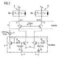
- FIG. 2 shows the circuit design of the differential amplifier cells 4. These differential amplifier cells 4 of FIG. 1 all have the same circuit design.
- the actual differential amplifier is formed by two n-channel MOS field effect transistors 13, 14 whose drain terminals are connected to a respective emitter terminal of the cascode transistors 6, 7 and their source terminals at the reference potential terminal 15.
- the gate terminals of the differential amplifier transistors 13, 14 are connected to the Nutzsignaleingang 1 via series coupling capacitances 16, which offer Hochpouleigenschaften.
- a current mirror is provided for operating point adjustment with a current mirror transistor 17, which is also formed as an n-channel field effect transistor and connected as a diode.
- the gate terminal of the current mirror transistor 17 is connected via a respective bias resistor 18 to the two gate terminals of the differential amplifier transistors 13, 14.
- the drain terminal of the current mirror transistor 17, which is connected to the gate terminal thereof, forms the activating input 11 of the differential amplifier 4.
- the external electrical load comprises a coil L C necessary for oscillating the output voltage by the operating voltage VCC, a resistive load resistor R L representing a surface acoustic wave band-pass filter downstream of the amplifier, and a complex load Z M , which represents a matching network.
- differential amplifier 4 advantageously manage without inductors.
- the high-frequency, to be amplified useful signal is fed via the coupling capacitances 16 and modulates the driven in the common-source circuit amplifier 13, 14. Its operating point is set with the current mirror transistor 17 and the resistors 18.
- the functions of the current source and of the amplifier in the transistors 13, 14 coincide, which has a particularly advantageous effect on the modulation range of the output signal.
- the sufficient linearity of the amplifier is thereby ensured that at the transistors 13, 14 a sufficient O-verdrive voltage is set.
- a ratio of signal current to quiescent current of less than 1 is ensured during operation. Due to the low impedance at the emitter input of the cascode transistors 6, 7, the voltage swing at the drain terminals of the amplifier transistors 13, 14 is largely suppressed.
- the current signal itself generates only at the high-impedance collector output of the cascode stage 6, 7 its voltage swing on the electrical load 9, 10.
- a quiescent current signal with a constant g m is used, which of the drive circuit 12th provided.
- the constant steepness value g m required for a constant output power is set via a resistance value and fixed by the use of a regulator.
- Figure 3 shows a development of the amplifier circuit with adjustable gain of Figure 1, in which the drive circuit 12 of the differential amplifier 4 is drawn in detail using an exemplary embodiment. All other components, their operation, their interconnection with each other and the advantageous operation of the amplifier circuit as a whole correspond to those of Figure 1 and are therefore not repeated at this point again.
- the drive circuit 12 comprises comparators, of which one each associated with a differential amplifier 4.
- the comparators are provided with reference numerals 19 to 22.
- the comparators 19 to 22 each have an output, which are connected to the enable input 11 of the associated differential amplifier 4 for supplying a respective differential amplifier 4 activating quiescent current.
- the comparators 19 to 22 each have two inputs. A respective first input of the comparators 19 to 22 is connected to the control input 3 of the amplifier, at which the amplification value of the amplifier is set.
- the second inputs of the comparators 19 to 22 are each connected to a tap node of a resistor string 23 to 27, which is connected between the reference potential 15 and a supply potential terminal 28.
- the resistors 23 to 27 are exponentially graded with respect to their values, so that exponentially graded threshold potentials are available at the tap nodes for the comparators 19 to 22. Thus, the exponential behavior of the amplifier is ensured with the advantages already explained in detail.
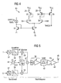
- FIG. 4 shows the comparator 19 of FIG. 3 on the basis of a detailed circuit diagram.
- the comparators 20 to 22 of FIG. 3 have the same structure as shown in FIG. 4.
- the core of the comparator 19 comprises two npn bipolar transistors, which are used as differential transistors 29, 30 connected to the comparator and are connected to each other emitter side.
- the common emitter node is connected to reference potential 15 via an n-channel field-effect transistor 31, which operates as a current source.
- the current source transistor 31 forms, with a diode-connected transistor 32, a current mirror, to the input of which a quiescent current is supplied, which effects a constant g m value in the amplifier transistors.
- the comparator 19 is constructed in BiCMOS circuit technology.
- FIG. 5 shows a preferred application of the gain-adjustable amplifier circuit 36 of FIG. 3 in the transmission path of a mobile radio device.
- this is a direct converter with complex-value signal processing, which has in its baseband unit an in-phase and a quadrature path I, Q for the complex-valued signal processing of a complex useful signal which has been decomposed into orthogonal components.
- I and Q paths each include a digital / analog converter 37 with a downstream low-pass filter 38, which are each connected to a first input of a mixer cell 39 of a quadrature mixer.
- the respective second inputs of the mixer cells 39 are connected via a 0/90 degree phase shifter 40 to an adjustable frequency generator 41, which generates a local oscillator signal.
- the quadrature mixer 39, 40 comprises a summing element 42 interconnecting the mixer cells 39 at their outputs. Accordingly, a modulated carrier signal is available at a high-frequency level at the output of the quadrature mixer 39, 40, 42. This is, depending on the desired transmission power or dependent on setpoints in control loops, amplified in the amplifier circuit 36 with adjustable gain in the desired manner and bandpass filtered in a downstream surface acoustic wave filter 43. The output of the bandpass filter 43 is connected to a transmitting antenna 45 via a power amplifier 44.
- FIG. 6 shows, on the basis of a diagram with a linear representation, the output power of the amplifier of FIG. 3 in mW plotted against the voltage value of the control signal adjacent to control input 3. It clearly recognizes the switching thresholds of the individual comparators 19 to 22 and the desired exponential curve of the characteristic curve. The accuracy of the exponential function of the characteristic curve is even more clearly visible on the basis of the following drawing.
- FIG. 7 shows the characteristic curve of FIG. 6, but plotted in semilogarithmic representation.
- the output power in dBmW is plotted against the control voltage in volts.
- the result is a linear relationship between control voltage and output power in dB, plotted on the basis of a straight line.
- the switching thresholds of the individual comparators which activate the differential amplifiers 4 are shown.
Abstract
Description
Die vorliegende Erfindung betrifft eine Verstärkerschaltung mit einstellbarer Verstärkung und eine Sendeanordnung mit der Verstärkerschaltung.The present invention relates to an amplifier circuit with adjustable gain and a transmission arrangement with the amplifier circuit.
In der Hochfrequenztechnik kommen ausgangsseitig im Sendepfad normalerweise sogenannte RF-Leistungsverstärker zum Einsatz. Beispielsweise bei Mobilfunkgeräten der dritten Generation, welche für UMTS (Universal Mobile Telecommunications Standard) ausgelegt sind, müssen auf einer Trägerfrequenzebene von ca. 2 Ghz sogenannte W-CDMA (Wide-Band Code Division Multiple Access)-Signale mit einer Bandbreite von zwei Megahertz über eine exponentielle Kennlinie verstärkt werden. Eine derartige, exponentielle Übertragungscharakteristik ist typisch für Variable Gain Amplifier, VGA und kann bei halblogarithmischer Darstellung als Gerade aufgetragen werden. Dabei wird normalerweise die Ausgangsleistung in Dezibel über der Steuerspannung des Verstärkers in Volt aufgetragen.In high-frequency technology, normally so-called RF power amplifiers are used in the transmission path on the output side. For example, in third-generation mobile phones, which are designed for UMTS (Universal Mobile Telecommunications Standard), so-called W-CDMA (Wide-Band Code Division Multiple Access) signals with a bandwidth of two megahertz must be on a carrier frequency level of about 2 Ghz an exponential characteristic can be amplified. Such an exponential transfer characteristic is typical for Variable Gain Amplifier, VGA and can be plotted as a straight line in semilogarithmic representation. Normally, the output power in decibels above the control voltage of the amplifier is plotted in volts.
An derartige, einstellbare Hochfrequenzverstärker werden hohe Anforderungen bezüglich Stromverbrauch, Wirkungsgrad, Linearität, Rauschen und Chipflächenbedarf gestellt. Letztere Anforderung führt zu Problemen des Übersprechens und in der Hochfrequenztechnik insbesondere zu unerwünschtem Durchscheinen von Trägerfrequenzen, Selbstmischeffekten et cetera. Der Stromverbrauch soll normalerweise deshalb gering sein, da derartige Mobilfunkgeräte normalerweise aus Batterien oder Akkumulatoren gespeist werden.At such adjustable radio frequency amplifier high demands are placed on power consumption, efficiency, linearity, noise and chip area requirements. The latter requirement leads to problems of crosstalk and in the high-frequency technology in particular to unwanted show through of carrier frequencies, self-mixing effects et cetera. The power consumption should normally be low because such mobile devices are usually powered by batteries or accumulators.
Leistungsverstärker im Hochfrequenzbereich werden normalerweise als induktiv degenerierte, in bipolarer Schaltungstechnik aufgebaute Differenzverstärker mit aufgeschalteter Stromkaskode realisiert.Power amplifiers in the high-frequency range are normally realized as inductively degenerated, constructed in bipolar circuit technology differential amplifier with connected current cascode.
Ein derartiger Differenzverstärker ist beispielsweise in dem Dokument
Die induktive Degenerierung des Differenzverstärkers mit zwischen dem gemeinsamen Emitterknoten des Verstärkers und den Emitteranschlüssen der beiden Differenzverstärkertransistoren geschalteten Induktivitäten bewirkt die erwünschte Stromgegenkopplung, welche bei hoher Güte ein nur geringes Eigenrauschen im Gesamtsystem bewirkt und die Linearisierung der Übertragungsfunktion ermöglicht.The inductive degeneration of the differential amplifier with connected between the common emitter node of the amplifier and the emitter terminals of the two differential amplifier transistors inductances causes the desired current negative feedback, which causes high noise only a little noise in the overall system and allows the linearization of the transfer function.
Bei der Verstärkung hochfrequenter Signale wirkt die Induktivität jedoch, insbesondere im GHz-Bereich, nachteilhafterweise als Antenne beziehungsweise Transformator und stellt somit ein unvermeidbares Problem für das Übersprechen von Signalen über das elektromagnetische Wechselfeld am integrierten Schaltkreis auf andere Schaltkreise dar. Ein weiteres Problem besteht in der Regelung der Leistungsabgabe des Verstärkers. Für die Verstärkung A gilt, daß A proportional ist zu dem Produkt aus gm,red und Rlast, wobei gm,red die Transkonduktanz der in Emitterschaltung betriebenen Differenzverstärkertransistoren repräsentiert. Rlast ist der an den offenen Kollektorausgang angeschlossene Lastwiderstand. Dabei wurde die Verstärkung der Kaskodestufe zu eins angenommen. Die Steilheit wird im Wesentlichen durch den Kollektorstrom und den Wert der Emitter-Degenerierung im relevanten Hochfrequenzbereich bestimmt gemäß der Vorschrift: 
mit gm gleich Steilheit, ZL gleich komplexer Degenerierungswiderstand, IC gleich Kollektorstrom und UT gleich Temperaturspannung.In the amplification of high-frequency signals, however, the inductance, especially in the GHz range, disadvantageously acts as an antenna or transformer and thus represents an unavoidable problem for the crosstalk of signals through the alternating electromagnetic field of the integrated circuit to other circuits Control of the power output of the amplifier. For gain A, A is proportional to the product of g m, red and R last , where g m, red is the transconductance of the emitter-operated differential amplifier transistors represents. R load is connected to the open collector output load resistor. The gain of the cascode level was assumed to be one. The steepness is essentially determined by the collector current and the value of the emitter degeneration in the relevant high-frequency range according to the rule:
with g m equal steepness, Z L equal to complex degeneration, I C equal to collector current and U T equal temperature voltage.
Man erkennt, daß eine Steuerung der Leistungsabgabe des Verstärkers nur durch einen Eingriff in dessen Ruhestromzufuhr möglich ist, wodurch der Arbeitspunkt des Verstärkers entsprechend nachteilhaft verschoben würde. Bei einem verhältnismäßig großen Verstärkungsbereich würden hierbei aber unerwünschte Nichtlinearitäten des Differenzverstärkers zum Tragen kommen.It can be seen that a control of the power output of the amplifier is possible only by engaging in its quiescent current supply, whereby the operating point of the amplifier would be shifted accordingly disadvantageous. In the case of a relatively large amplification range, however, unwanted nonlinearities of the differential amplifier would come into play here.
Das Dokument
Das Dokument
In dem Dokument 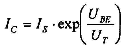
eine exponentielle Kennlinie des Verstärkers für eine in halblogarithmischer Darstellung lineare Regelung. Der gravierenste Nachteil einer derartigen Leistungsregelung ist durch die konstante Stromaufnahme des Leistungsverstärkers gegeben. Nur unter Zuhilfenahme einer nicht unbedeutetenden Hilfsenergiemenge für den Steuerblock ist es möglich, einen Stromsparmodus bereitzustellen. Der Verstärker selbst benötigt in jedem Punkt der Kennlinie eine konstante Leistung, wodurch sich der Wirkungsgrad der Gesamtschaltung beim Herunterregeln der Ausgangsleistung signifikant reduziert.In the document
an exponential characteristic of the amplifier for a semi-logarithmic linear representation. The most serious disadvantage of such a power control is given by the constant current consumption of the power amplifier. Only with the aid of a non-negligible amount of auxiliary power for the control block is it possible to provide a power-saving mode. The amplifier itself requires constant power at each point of the characteristic curve, which significantly reduces the overall circuit efficiency when derating the output power.
Aufgabe der vorliegenden Erfindung ist es, einen zur Verstärkung hochfrequenter Signale geeigneten Verstärker mit einstellbarer Verstärkung anzugeben, welcher einen großen einstellbaren Verstärkungsbereich hat, stromsparend arbeitet und ein unerwünschtes Übersprechen von Signalen verhindert.The object of the present invention is to provide a suitable gain amplifier for high-frequency signals with adjustable gain, which has a large adjustable gain range, works to save energy and prevents unwanted crosstalk of signals.
Erfindungsgemäß wird die Aufgabe gelöst durch eine Verstärkerschaltung mit einstellbarer Verstärkung, aufweisend
- ein Eingang zur Zuführung eines Differenzsignals,
- einen Ausgang zum Ableiten eines verstärkten Signals,
- einen Steuereingang zum Zuführen eines Verstärkungsfaktors,
- eine Kaskodestufe, die an den Ausgang angeschlossen ist, umfassend zwei steuerseitig miteinander gekoppelte Kaskode-Transistoren,
- mehrere, parallelgeschaltete Differenzverstärker, mit je einem Eingang, der mit dem Eingang verbunden ist, mit je einem Ausgang, der mit der Kaskodestufe verbunden ist, und mit je einem Aktiviereingang, und
- eine Ansteuereinheit, mit einem Eingang, der an den Steuereingang der Verstärkerschaltung angeschlossen ist, und mit mehreren Ausgängen, von denen je einer mit je einem Differenzverstärker an dessen Aktiviereingang verbunden ist zum Aktivieren eines oder mehrerer Differenzverstärker in Abhängigkeit von dem am Steuereingang zugeführten Verstärkungsfaktor, wobei der einem Differenzverstärker zugeordnete Aktiviereingang mit einem Stromspiegeltransistor gekoppelt ist, der mit zwei Verstärkertransistoren des Differenzverstärkers jeweils einen Stromspiegel bildet zur Zuführung eines Referenzstroms in Abhängigkeit von einem am Aktiviereingang anliegenden Signal.
- an input for supplying a difference signal,
- an output for deriving an amplified signal,
- a control input for supplying a gain,
- a cascode stage connected to the output, comprising two cascode transistors coupled together on the control side,
- a plurality of differential amplifiers connected in parallel, each having one input connected to the input, one output connected to the cascode stage and one activating input, and
- a drive unit having an input which is connected to the control input of the amplifier circuit, and having a plurality of outputs, one of which is each connected to a differential amplifier at its enable input for activating one or more differential amplifiers in dependence on the supplied at the control input gain factor the one assigned to a differential amplifier Activating input is coupled to a current mirror transistor, which forms a current mirror with two amplifier transistors of the differential amplifier for supplying a reference current in response to a signal applied to the activation input signal.
Die parallelgeschalteten Differenzverstärkerstufen, welche untereinander einen gleichartigen Schaltungsaufbau besitzen, sind mit ihren Ausgängen miteinander verbunden und an eine gemeinsame Kaskodestufe angeschlossen.The parallel-connected differential amplifier stages, which have a similar circuit structure with each other, are connected to each other with their outputs and connected to a common cascode stage.
Bevorzugt arbeitet jede einzelne Verstärkerzelle in einem Arbeitspunkt, der bezüglich Linearität und Rauschen optimiert eingestellt ist. Die Differenzverstärker sind unabhängig von einander zu- und abschaltbar. Jede eingeschaltete Differenzverstärkerzelle liefert ihren Beitrag zur Gesamtverstärkung. Diese Beiträge, die bevorzugt als Stromanteile vorliegen, werden an dem Eingang der Kaskodestufe addiert und an den Ausgang der Kaskodestufe und damit den Ausgang der Verstärkerschaltung mit einstellbarer Verstärkung übertragen. Die Ansteuerung der einzelnen Differenzverstärker erfolgt über die Ansteuereinheit, welche nach einer vorbestimmten Zuordnungsvorschrift das eingangsseitige Steuersignal, beispielsweise eine Eingangsspannung, auf eine beliebige Kennlinie abbildet.Preferably, each individual amplifier cell operates at an operating point that is optimized in terms of linearity and noise. The differential amplifiers can be switched on and off independently of each other. Each powered differential amplifier cell provides its contribution to the overall gain. These contributions, which are preferably present as current components, are added at the input of the cascode stage and transmitted to the output of the cascode stage and thus to the output of the amplifier circuit with adjustable gain. The control of the individual differential amplifier via the drive unit, which maps the input-side control signal, for example, an input voltage on any characteristic according to a predetermined assignment rule.
Bevorzugt wird die Steuerspannung auf eine exponentielle Leistungskennlinie durch entsprechendes Zu- und Abschalten einzelner Differenzverstärker auf eine exponentielle Leistungskennlinie abgebildet. Eine effiziente Stromausnutzung der Leistungsregelung wird dadurch erreicht, daß in einem bestimmten Kennlinienpunkt immer nur so viele Differenzverstärkerzellen eingeschaltet sind, wie zur Bereitstellung einer gewünschten Ausgangsleistung benötigt werden. Somit ist über den gesamten Verstärkungsbereich die Leistungsfähigkeit der vorliegenden Verstärkerschaltung bezüglich Rauschen, Linearität, Verzerrungen und Wirkungsgrad sichergestellt.Preferably, the control voltage is mapped to an exponential power characteristic by corresponding connection and disconnection of individual differential amplifiers to an exponential power characteristic. An efficient power utilization of the power control is achieved in that in a certain characteristic point only as many differential amplifier cells are turned on, as are needed to provide a desired output power. Thus, over the entire gain range, the performance of the present amplifier circuit is ensured in terms of noise, linearity, distortion and efficiency.
Die einzelnen parallel geschalteten Differenzverstärker haben bevorzugt einen gleichen Schaltungsaufbau.The individual parallel-connected differential amplifiers preferably have the same circuit configuration.
Der beschriebene Aufbau der Verstärkerschaltung mit mehreren, parallel geschalteten Differenzverstärkerstufen, die eine gemeinsame Kaskodestufe speisen, ermöglicht es, ohne Nachteile auf Einsatz von Induktivitäten zur induktiven Degenerierung in den einzelnen Differenzverstärkerzellen vollständig zu verzichten. Somit ist die vorliegende Schaltung für höhere Integrationsdichten bei Frequenzen im Gigahertz-Bereich geeignet, da Probleme durch Übersprechen deutlich verringert sind.The described structure of the amplifier circuit with a plurality of parallel-connected differential amplifier stages, which feed a common cascode stage, makes it possible to dispense completely without disadvantages on the use of inductors for inductive degeneration in the individual differential amplifier cells. Thus, the present circuit is suitable for higher integration densities at gigahertz frequencies because crosstalk problems are significantly reduced.
Die Ansteuereinheit ist mit den Aktiviereingängen der parallel geschalteten Differenzverstärker bevorzugt über einen Stromspiegel mit Gegenkopplungswiderstand oder Biaswiderstand angeschlossen, der die Steuereingänge der Differenzverstärkertransistoren speist. Die Steuereingänge der Differenzverstärkertransistoren sind dabei über je einen Widerstand an einen gemeinsamen Knoten im Stromspiegel verbunden und arbeiten als Ausgangstransistoren des Stromspiegels.The drive unit is connected to the activation inputs of the differential amplifiers connected in parallel, preferably via a current mirror with negative feedback resistance or bias resistor, which feeds the control inputs of the differential amplifier transistors. The control inputs of the differential amplifier transistors are connected via a respective resistor to a common node in the current mirror and work as output transistors of the current mirror.
Das hochfrequente, zu verstärkende Signal wird bevorzugt über eine durch Serienkondensatoren realisierte Wechselstromkopplung eingespeist.The high-frequency signal to be amplified is preferably fed via an AC coupling realized by series capacitors.
Der Differenzverstärker ist bevorzugt in Common-Source-Schaltung aufgebaut, das heißt, daß die Source- oder Emitter-Anschlüsse der Differenzverstärkertransistoren miteinander verbunden sind.The differential amplifier is preferably constructed in common-source circuit, that is, that the source or emitter terminals of the differential amplifier transistors are interconnected.
Der Arbeitspunkt wird bevorzugt über die Biaswiderstände und den Stromspiegel eingestellt. Somit fällt die Funktion der Stromquellen und des Verstärkers in den beiden Differenzverstärkertransistoren zusammen, so daß das Ausgangssignal einen großen Aussteuerbereich hat.The operating point is preferably set via the bias resistors and the current mirror. Thus, the function of the current sources and the amplifier in the two differential amplifier transistors coincide so that the output signal has a large drive range.
Die Verstärkertransistoren sind bevorzugt als Feldeffekttransistoren ausgeführt. Die Kaskode-Transistoren, welche für alle Differenzverstärker eine gemeinsame Kaskodestufe bilden, sind bevorzugt in bipolarer Schaltungstechnik ausgeführt.The amplifier transistors are preferably designed as field effect transistors. The cascode transistors, which form a common cascode stage for all differential amplifiers, are preferably implemented using bipolar circuit technology.
Hierdurch werden die Linearitätseigenschaften des Verstärkers weiter deutlich verbessert. Auf Grund der Niederohmigkeit an den Emittereingängen der Kaskodetransistoren wird der Spannungshub an den Drainanschlüssen der Verstärkertransistoren weitgehend unterdrückt, das Stromsignal selbst erzeugt erst am hochohmigen Kollektorausgang der Kaskode seinen Spannungshub an einer anzuschließenden Last.As a result, the linearity properties of the amplifier are further improved significantly. Due to the low impedance at the emitter inputs of the cascode transistors of the voltage swing at the drain terminals of the amplifier transistors is largely suppressed, the current signal itself generates only at the high-impedance collector output of the cascode its voltage swing at a load to be connected.
Die Ansteuerung des Aktiviereingangs der einzelnen Differenzverstärker erfolgt bevorzugt durch je einen zugeordneten Komparator, der in der Ansteuereinheit vorgesehen ist. Den Komparatoren wird an je einem Eingang das Soll-Signal mit der gewünschten Verstärkung der Verstärkerschaltung und an je einem anderen Eingang ein jeweiliger, abgestufter Schwellwert zugeführt.The activation of the activation input of the individual differential amplifiers is preferably carried out by an associated comparator, which is provided in the drive unit. The comparators each receive an input to the desired signal with the desired gain of the amplifier circuit and at each other a respective input, graded threshold.
Diese Vergleichsspannungen oder Vergleichssignale sind bevorzugt exponentiell abgestuft und werden beispielsweise durch eine Widerstandskette, die einen Spannungsteiler bildet, bereitgestellt.These comparison voltages or comparison signals are preferably stepped exponentially and are provided for example by a resistor chain which forms a voltage divider.
Die Komparatoren sind bevorzugt in bipolarer Schaltungstechnik ausgeführt. Hierdurch werden die Differenzverstärker gemäß einer Tangens Hyperbolicus-Kennlinie eingeschaltet, wodurch sich ein besonders sanfter Übergang entlang der gewünschten Ausgangskennlinie mit mäßiger Steilheit ergibt. Somit sind insbesondere nachteilhafte Auswirkungen auf übergeordnete Regelschleifen, in denen die vorliegende Verstärkerschaltung angeordnet werden kann, ausgeschlossen.The comparators are preferably designed in bipolar circuit technology. As a result, the differential amplifiers are turned on according to a tangent hyperbolic characteristic, resulting in a particularly smooth transition along the desired output characteristic with moderate slope. Thus, in particular adverse effects on higher-level control loops, in which the present amplifier circuit can be arranged excluded.
Anstelle der exponentiell abgestuften Schwellwerte als Vergleichpotentiale für die Komparatoren ist es auch möglich, eine lineare Abstufung der Schwellwerte einzusetzen und die Gewichtung der Verstärkungsbeiträge der einzelnen Differenzverstärkerzellen entsprechend zu verändern, so daß insgesamt ebenfalls eine exponentielle Kennlinie des Verstärkers resultiert.Instead of the exponentially graded threshold values as comparison potentials for the comparators, it is also possible to use a linear gradation of the threshold values and to correspondingly change the weighting of the gain contributions of the individual differential amplifier cells, so that overall an exponential characteristic of the amplifier also results.
Allgemein kann mit dem vorgestellten Prinzip eine beliebige, beispielsweise eine logarithmische, lineare oder exponentielle Kennlinie der Ausgangsleistung in Abhängigkeit von der Steuerspannung erzeugt werden.In general, any desired, for example, a logarithmic, linear or exponential characteristic of the output power as a function of the control voltage can be generated with the presented principle.
Der vorliegende Verstärker ist insbesondere zur Anwendung in Mobilfunksendern mit Direktumsetzung des Basisbands in die Hochfrequenzebene geeignet und zur Anwendung in Geräten gemäß UMTS (Universal Mobile Telecommunications Standard), welche mit Code-Vielfachzugriffsverfahren (CDMA) arbeiten, vorgesehen.The present amplifier is particularly suitable for use in mobile radio transmitters with direct conversion of the baseband to the high-frequency level and for use in devices according to UMTS (Universal Mobile Telecommunications Standard), which operate with code-division multiple access (CDMA).
Weitere Einzelheiten und vorteilhafte Ausgestaltungen der vorliegenden Erfindung sind Gegenstand der Unteransprüche.Further details and advantageous embodiments of the present invention are subject of the dependent claims.
Die Erfindung wird nachfolgend anhand von Ausführungsbeispielen an mehreren Zeichnungen näher erläutert. Es zeigen:
Figur 1- ein Ausführungsbeispiel der vorliegenden Erfindung anhand eines Blockschaltbildes,
Figur 2- eine beispielhafte Ausführung der
Verstärkerzellen von Figur 1 anhand eines Schaltplanes, Figur 3- eine Weiterbildung der
Verstärkerschaltung von Figur 1 mit Komparatoren zur Ansteuerung der Differenzverstärker, Figur 4- eine beispielhafte Ausführung eines
Komparators von Figur 3 anhand eines Schaltplanes, - Figur 5
- ein Blockschaltbild eines Sendepfades mit der
Verstärkerschaltung von Figur 1oder 3, - Figur 6
- die Kennlinie der Ausgangsleistung aufgetragen über der Steuerspannung in linearer Darstellung gemäß der
Verstärkerschaltung von Figur 3 und - Figur 7
- das Schaubild von Figur 6, jedoch in halblogarithmischer Darstellung.
- FIG. 1
- An embodiment of the present invention with reference to a block diagram,
- FIG. 2
- an exemplary embodiment of the amplifier cells of Figure 1 using a circuit diagram,
- FIG. 3
- 1 shows a development of the amplifier circuit of FIG. 1 with comparators for controlling the differential amplifiers;
- FIG. 4
- an exemplary embodiment of a comparator of Figure 3 using a circuit diagram,
- FIG. 5
- 2 is a block diagram of a transmission path with the amplifier circuit of FIG. 1 or 3,
- FIG. 6
- the characteristic of the output power plotted against the control voltage in a linear representation according to the amplifier circuit of Figure 3 and
- FIG. 7
- the graph of Figure 6, but in semi-logarithmic representation.
Figur 1 zeigt eine Verstärkerschaltung mit einstellbarem Verstärkungswert. Diese weist einen Nutzsignaleingang 1 zum Zuführen eines differentiellen Nutzsignals auf, der als Eingang ausgebildet ist. Das verstärkte Nutzsignal kann am Ausgangsklemmenpaar 2, 2' des Verstärkers abgeleitet werden. An einem Steuereingang 3 ist ein Soll-Signal für einen gewünschten Verstärkungswert des Verstärkers als Spannungssignal zuführbar. An dem Eingang 1 sind mit ihren jeweiligen Eingängen mehrere, miteinander in einer Parallelschaltung verschaltete Differenzverstärker 4 angeschlossen. An deren ebenfalls differentiell ausgeführten Ausgangsklemmenpaaren, welche miteinander verbunden sind, ist eine gemeinsame Kaskodestufe 5 angeschlossen, welche zwei Kaskodetransistoren 6, 7 umfaßt. Die Kaskodetransistoren 6, 7 sind in bipolarer Schaltungstechnik ausgeführt und mit ihren Basisanschlüssen miteinander und einem Biasspannungseingang 8 verbunden. Das Emitterausgangspaar ist mit den Ausgangsklemmenpaaren der Differenzverstärker 4 verbunden. Das Kollektoranschlußpaar der npn-Transistoren 6, 7 bildet das Ausgangsklemmenpaar 2, 2' des Verstärkers. An den Verstärkerausgang 2, 2' sind externe, elektrische Lasten 9, 10 angeschlossen. Die externen, elektrischen Lasten 9, 10 sind beispielhaft und in vereinfachter Darstellung jeweils als Parallelschaltungen einer ohmschen Last RL, einer komplexen Last ZM sowie einer Induktivität LC ausgeführt. Die Differenzverstärker 4 weisen neben ihrem Eingang und ihrem Ausgangsklemmenpaar, welche jeweils miteinander parallel geschaltet sind, weiterhin je einen Aktiviereingang 11 auf. Die Aktiviereingänge 11 der Differenzverstärker 4 sind an je einen zugeordneten Ausgang einer Ansteuereinheit 12 angeschlossen, welche eingangsseitig mit dem Steuereingang 3 verbunden ist und in Abhängigkeit von einem anliegenden Steuersignal einen oder mehrere der getrennt voneinander zu- und abschaltbaren Differenzverstärkerzellen 4 aktiviert.Figure 1 shows an amplifier circuit with adjustable gain value. This has a
Jede Differenzverstärkerzelle 4 verarbeitet in ihrem für Linearität und Rauschen optimierten Betriebspunkt das gleiche Eingangssignal und liefert ihren Beitrag für die Gesamtverstärkung. Diese Strombeiträge werden am niederohmigen Eingang der Kaskode 5 addiert und in den Off-chip-Lastwiderständen 9, 10 in Leistung umgesetzt. Die Ansteuerung der einzelnen Differenzverstärkerzellen 4 erfolgt über die Ansteuereinheit 12, welche nach einer vorbestimmten Zuordnungsvorschrift im allgemeinen Fall ein eingangsseitiges Steuersignal auf eine beliebige Kennlinie, vorliegend eine exponentielle Leistungskennlinie abbildet. Die Aktivierung der Differenzverstärker 4 erfolgt dabei über deren Ruhestromzuführung, englisch Bias.Each
Die beschriebene Verstärkerschaltung bietet einen großen einstellbaren Verstärkungsbereich, gute Rauscheigenschaften, sowie gute Linearitätseigenschaften bezüglich Verzerrungen. Außerdem ist der Strombedarf auf Grund der gezeigten Struktur stets an die aktuelle Leistungsabgabe angepaßt. Da somit in den einzelnen Differenzverstärkern 4 auf induktive Degeneration verzichtet werden kann, ist auch das Übersprechen gering und die Hochfrequenzeigenschaften sind auch im Gigahertz-Bereich gut.The described amplifier circuit provides a large adjustable gain range, good noise characteristics, and good linearity characteristics with respect to distortion. In addition, the power requirement is always adapted to the current power output due to the structure shown. Since inductive degeneration can thus be dispensed with in the individual
Figur 2 zeigt den schaltungstechnischen Aufbau der Differenzverstärkerzellen 4. Diese Differenzverstärkerzellen 4 von Figur 1 haben alle den gleichen schaltungstechnischen Aufbau.FIG. 2 shows the circuit design of the
Der eigentliche Differenzverstärker ist von zwei n-Kanal MOS-Feldeffekttransistoren 13, 14 gebildet, deren Drainanschlüsse an je einen Emitteranschluß der Kaskodetransistoren 6, 7 und deren Source-Anschlüsse am Bezugspotentialanschluß 15 angeschaltet sind. Die Gate-Anschlüsse der Differenzverstärkertransistoren 13, 14 sind über Serien-Koppelkapazitäten 16, welche Hochpaßeigenschaften bieten, an den Nutzsignaleingang 1 angeschlossen. Außerdem ist zur Arbeitspunkteinstellung ein Stromspiegel vorgesehen mit einem Stromspiegeltransistor 17, der ebenfalls als n-Kanal-Feldeffekttransistor ausgebildet und als Diode verschaltet ist. Der Gate-Anschluß des Stromspiegeltransistors 17 ist über je einen Biaswiderstand 18 mit den beiden Gate-Anschlüssen der Differenzverstärkertransistoren 13, 14 verbunden. Der Drain-Anschluß des Stromspiegeltransistors 17, der mit dem Gate-Anschluß desselben verbunden ist, bildet den Aktiviereingang 11 des Differenzverstärkers 4.The actual differential amplifier is formed by two n-channel MOS
Die externe elektrische Last umfaßt wie bei Figur 1 eine Spule LC, die für das Schwingen der Ausgangsspannung um die Betriebsspannung VCC nötig ist, einen ohmschen Lastwiderstand RL, der ein Oberflächenwellen-Bandpaßfilter repräsentiert, welches dem Verstärker nachgeschaltet ist, sowie eine komplexe Last ZM, welche ein Anpaßnetzwerk repräsentiert.As in FIG. 1, the external electrical load comprises a coil L C necessary for oscillating the output voltage by the operating voltage VCC, a resistive load resistor R L representing a surface acoustic wave band-pass filter downstream of the amplifier, and a complex load Z M , which represents a matching network.
Man erkennt, daß die Differenzverstärker 4 mit Vorteil ohne Induktivitäten auskommen.It can be seen that the
Das hochfrequente, zu verstärkende Nutzsignal wird über die Koppelkapazitäten 16 eingespeist und moduliert den in Common-Source-Schaltung betriebenen Verstärker 13, 14. Dessen Arbeitspunkt wird mit dem Stromspiegeltransistor 17 und den Widerständen 18 eingestellt. Vorteilhafterweise fallen die Funktionen der Stromquelle und des Verstärkers in den Transistoren 13, 14 zusammen, was sich insbesondere vorteilhaft auf den Aussteuerbereich des Ausgangssignals auswirkt. Die ausreichende Linearität des Verstärkers ist dadurch sichergestellt, daß an den Transistoren 13, 14 eine ausreichende O-verdrive-Spannung eingestellt ist. Somit ist ein Verhältnis von Signalstrom zu Ruhestrom von kleiner 1 während des Betriebes gewährleistet. Durch die Niederohmigkeit am Emittereingang der Kaskodetransistoren 6, 7 wird der Spannungshub an den Drainanschlüssen der Verstärkertransistoren 13, 14 weitgehend unterdrückt. Das Stromsignal selbst erzeugt erst am hochohmigen Kollektorausgang der Kaskodestufe 6, 7 seinen Spannungshub an der elektrischen Last 9, 10. Damit die gewünschte Verstärkung auch über den gesamten Einsatztemperaturbereich garantiert werden kann, wird ein Ruhestromsignal mit konstantem gm verwendet, welches von der Ansteuerschaltung 12 bereitgestellt wird. In der Differenzverstärkerschaltung 4 wird der für eine konstante Ausgangsleistung benötigte konstante Steilheitswert gm über einen Widerstandswert eingestellt und durch den Einsatz eines Reglers fixiert.The high-frequency, to be amplified useful signal is fed via the
Figur 3 zeigt eine Weiterbildung der Verstärkerschaltung mit einstellbarer Verstärkung von Figur 1, bei der die Ansteuerschaltung 12 der Differenzverstärker 4 anhand eines Ausführungsbeispiels detailliert gezeichnet ist. Alle übrigen Bauteile, deren Funktionsweise, ihre Verschaltung miteinander und die vorteilhafte Funktionsweise der Verstärkerschaltung insgesamt entsprechen denen von Figur 1 und werden daher an dieser Stelle nicht noch einmal wiederholt.Figure 3 shows a development of the amplifier circuit with adjustable gain of Figure 1, in which the drive circuit 12 of the
Die Ansteuerschaltung 12 umfaßt Komparatoren, von denen je einer je einem Differenzverstärker 4 zugeordnet ist. Die Komparatoren sind mit Bezugszeichen 19 bis 22 versehen. Die Komparatoren 19 bis 22 haben je einen Ausgang, der mit dem Aktiviereingang 11 des zugeordneten Differenzverstärkers 4 zur Zuführung eines den jeweiligen Differenzverstärker 4 aktivierenden Ruhestromes verbunden sind. Die Komparatoren 19 bis 22 haben je zwei Eingänge. Je ein erster Eingang der Komparatoren 19 bis 22 ist mit dem Steuereingang 3 des Verstärkers verbunden, an dem der Verstärkungswert des Verstärkers eingestellt wird. Die zweiten Eingänge der Komparatoren 19 bis 22 sind mit je einem Abgriffsknoten einer Widerstandskette 23 bis 27 verbunden, die zwischen das Bezugspotential 15 und einen Versorgungspotentialanschluß 28 geschaltet ist. Die Widerstände 23 bis 27 sind bezüglich ihrer Werte exponentiell abgestuft, so daß an den Abgriffknoten exponentiell abgestufte Schwellwertpotentiale für die Komparatoren 19 bis 22 bereitstehen. Somit ist das exponentielle Verhalten des Verstärkers mit den bereits ausführlich erläuterten Vorteilen sichergestellt.The drive circuit 12 comprises comparators, of which one each associated with a
Figur 4 zeigt anhand eines detaillierten Schaltplanes den Komparator 19 von Figur 3. Einen ebensolchen Aufbau wie in Figur 4 gezeigt haben auch die Komparatoren 20 bis 22 von Figur 3. Der Kern des Komparators 19 umfaßt zwei npn-Bipolartransistoren, welche als Differenztransistoren 29, 30 des Komparators verschaltet und emitterseitig miteinander verbunden sind. Der gemeinsame Emitterknoten ist über einen n-Kanal-Feldeffekttransistor 31, der als Stromquelle arbeitet, gegen Bezugspotential 15 geschaltet. Der Stromquellentransistor 31 bildet mit einem als Diode verschalteten Transistor 32 einen Stromspiegel, an dessen Eingang ein Ruhestrom zugeführt wird, der in den Verstärkertransistoren einen konstanten gm-Wert bewirkt. Kollektorseitig sind die Differenztransistoren 29, 30 des Komparators 19 über je eine Diode 33, 34 an Versorgungspotentialanschluß 28 geschaltet. An einer der beiden Dioden wird dabei das Ausgangssignal des Komparators 29, 30 über einen Stromspiegel ausgekoppelt, den ein weiterer MOS-Transistor 35 zusammen mit der Diode 34 bildet. Der Drain-Anschluß des Stromspiegeltransistors 35 ist mit einem Aktiviereingang 11 eines hier nicht eingezeichneten Differenzverstärkers 4 verbunden zur Aktivierung desselben, wie in Figur 3 gezeigt.FIG. 4 shows the
Insgesamt ist der Komparator 19 in BiCMOS-Schaltungstechnik aufgebaut.Overall, the
Auf Grund des Einsatzes von bipolarer Schaltungstechnik in dem Kern des Komparators 19 und der übrigen Komparatoren 20 bis 22 erfolgt das Aktivieren der Differenzverstärker 4 gemäß einer Tangens-Hyperbolicus-Kennlinie, wodurch sich mit Vorteil ein besonders sanfter Übergang entlang der gewünschten Ausgangskennlinie mit mäßiger Steilheit der Verstärkungskennlinie ergibt.Due to the use of bipolar circuit technology in the core of the
Figur 5 zeigt eine bevorzugte Anwendung der Verstärkerschaltung mit einstellbarer Verstärkung 36 von Figur 3 im Sendepfad eines Mobilfunkgerätes. Es handelt sich vorliegend um einen Direktumsetzer mit komplexwertiger Signalverarbeitung, der in seiner Basisbandeinheit einen Inphase- und einen Quadraturpfad I, Q zur komplexwertigen Signalverarbeitung eines in orthogonale Komponenten zerlegten, komplexen Nutzsignals hat. I- und Q-Pfad umfassen je einen Digital/Analog-Wandler 37 mit nachgeschaltetem Tiefpaßfilter 38, welche an je einen ersten Eingang einer Mischerzelle 39 eines Quadraturmischers angeschlossen sind. Die jeweils zweiten Eingänge der Mischerzellen 39 sind über einen 0/90 Grad-Phasenschieber 40 an einen verstellbaren Frequenzgenerator 41, der ein Lokaloszillatorsignal erzeugt, angeschlossen. Der Quadraturmischer 39, 40 umfaßt ein die Mischerzellen 39 an ihren Ausgängen miteinander verbindendes Summierglied 42. Am Ausgang des Quadraturmischers 39, 40, 42 steht demnach ein moduliertes Trägersignal auf einer Hochfrequenzebene bereit. Dieses wird, je nach gewünschter Sendeleistung oder abhängig von Sollwerten in Regelschleifen, in der Verstärkerschaltung 36 mit einstellbarer Verstärkung in gewünschter Weise verstärkt und in einem nachgeschalteten Oberflächenwellenfilter 43 bandpaßgefiltert. Der Ausgang des Bandpaßfilters 43 ist über einen Leistungsverstärker 44 an eine Sendeantenne 45 angeschlossen.FIG. 5 shows a preferred application of the gain-
In einem derartigen Direktumsetzer kommen die Vorteile des vorliegenden Verstärkers, wie hohe Linearität, geringe Verzerrungen, hohe Integrierbarkeit bei geringem Übersprechen und geringer an die aktuelle Leistungsabgabe angepaßter Stromverbrauch besonders vorteilhaft zum Tragen.In such a direct converter come the advantages of the present amplifier, such as high linearity, low distortion, high integration with low crosstalk and less adapted to the current power consumption adapted power consumption particularly advantageous.
Figur 6 zeigt an Hand eines Schaubildes mit linearer Darstellung die Ausgangsleistung des Verstärkers von Figur 3 in mW aufgetragen über dem Spannungswert des Steuersignals anliegend an Steuereingang 3. Man erkennt deutlich die Umschaltschwellen der einzelnen Komparatoren 19 bis 22 und den gewünschten exponentiellen Verlauf der Kennlinie. Die Genauigkeit der Exponentialfunktion der Kennlinie ist an Hand der nachfolgenden Zeichnung noch deutlicher sichtbar.FIG. 6 shows, on the basis of a diagram with a linear representation, the output power of the amplifier of FIG. 3 in mW plotted against the voltage value of the control signal adjacent to control
Figur 7 zeigt den Kennlinienverlauf der Figur 6, jedoch aufgetragen in halblogarithmischer Darstellung. Dabei ist die Ausgangsleistung in dBmW aufgetragen über der Steuerspannung in Volt. Es ergibt sich ein an Hand einer Geraden aufgetragener, linearer Zusammenhang zwischen Steuerspannung und Ausgangsleistung in dB. Auch bei der Darstellung von Figur 7 sind die Umschaltschwellen der einzelnen Komparatoren, die die Differenzverstärker 4 aktivieren, eingezeichnet.FIG. 7 shows the characteristic curve of FIG. 6, but plotted in semilogarithmic representation. The output power in dBmW is plotted against the control voltage in volts. The result is a linear relationship between control voltage and output power in dB, plotted on the basis of a straight line. Also in the illustration of FIG. 7, the switching thresholds of the individual comparators which activate the
- 11
- Eingangentrance
- 22
- Ausgangoutput
- 2'2 '
- Ausgangoutput
- 33
- Steuereingangcontrol input
- 44
- Differenzverstärkerdifferential amplifier
- 55
- Kaskodecascode
- 66
- Kaskodetransistorcascode
- 77
- Kaskodetransistorcascode
- 88th
- Bias-EingangBias input
- 99
- elektrische Lastelectrical load
- 1010
- elektrische Lastelectrical load
- 1111
- Aktiviereingangactivation input
- 1212
- Ansteuereinheitcontrol unit
- 1313
- Verstärkertransistoramplifier transistor
- 1414
- Verstärkertransistoramplifier transistor
- 1515
- MasseDimensions
- 1616
- WechselstromkopplungAC coupling
- 1717
- Diodediode
- 1818
- Widerstandresistance
- 1919
- Komparatorcomparator
- 2020
- Komparatorcomparator
- 2121
- Komparatorcomparator
- 2222
- Komparatorcomparator
- 2323
- Widerstandresistance
- 2424
- Widerstandresistance
- 2525
- Widerstandresistance
- 2626
- Widerstandresistance
- 2727
- Widerstandresistance
- 2828
- Versorgungspotentialsupply potential
- 2929
- Differenztransistordifferential transistor
- 3030
- Differenztransistordifferential transistor
- 3131
- Stromspiegelcurrent mirror
- 3232
- Stromspiegelcurrent mirror
- 3333
- Diodediode
- 3434
- Diodediode
- 3535
- Stromspiegelcurrent mirror
- 3636
- Verstärkeramplifier
- 3737
- DACDAC
- 3838
- Tiefpaßfilterlow pass filter
- 3939
- Mischermixer
- 4040
- Phasenschieberphase shifter
- 4141
- VCOVCO
- 4242
- Summiergliedsumming
- 4343
- SAW-FilterSAW filter
- 4444
- Leistungsverstärkerpower amplifier
- 4545
- Antenneantenna
Claims (8)
- Amplifier circuit with adjustable gain, having- an input (1) for supplying a differential signal,- an output (2, 2') for deriving an amplified signal,- a control input (3) for supplying a gain factor,- a cascode stage (5) which is connected to the output (2, 2') and comprises two cascode transistors (6, 7) coupled to one another on the control side,- a plurality of differential amplifiers (4) connected in parallel, with a respective input which is connected to the input (1), with a respective output which is connected to the cascode stage (5), and with a respective activation input (11), and- an actuation unit (12), with an input which is connected to the control input (3) of the amplifier circuit, and with a plurality of outputs, a respective one of which is connected to the activation input (11) of a respective differential amplifier (4) for the purpose of activating one or more differential amplifiers (4) on the basis of the gain factor supplied at the control input (3),characterized in that
the activation input (11) associated with a differential amplifier (4) being coupled to a current mirror transistor (17) which forms a respective current mirror together with two amplifier transistors (13, 14) in the differential amplifier in order to supply a reference current on the basis of a signal applied to the activation input (11). - Amplifier circuit according to Claim 1,
characterized in that
the respective two amplifier transistors (13, 14) in the differential amplifiers (4) each comprise a control input and a controlled section, the control inputs of the differential amplifier (13, 14) being coupled to the input (1) of the amplifier circuit, and the controlled sections each coupling an associated cascode transistor (6, 7) to a reference potential connection. - Amplifier circuit according to Claim 1 or 2,
characterized in that
the amplifier transistors (13, 14) are in the form of field effect transistors, and the cascode transistors (6, 7) are in the form of bipolar transistors. - Amplifier circuit according to one of Claims 1 to 3,
characterized in that
the actuation unit (12) comprises a plurality of comparators (19, 20, 21, 22), a respective one of which has its output connected to the activation input (11) of an associated differential amplifier (4), the comparators (19, 20, 21, 22) each having a first input, which is coupled to the control input (3) of the amplifier circuit, and a second input for supplying a respective, graduated threshold value. - Amplifier circuit according to Claim 4,
characterized in that
a divider chain (23, 24, 25, 26, 27) is provided which has a plurality of exponentially graduated tap nodes, a respective one of which is connected to a second input on an associated comparator (19, 20, 21, 22) in order to provide exponentially graduated threshold values. - Amplifier circuit according to Claim 4 or 5,
characterized in that
the comparators (19, 20, 21, 22) each comprise a differential amplifier with two differential transistors (29, 30) whose control inputs form the inputs of the comparator (19, 20, 21, 22), and
characterized in that the output of the comparator (19, 20, 21, 22) is coupled to one of the two differential transistors (30) via a current mirror (34, 35). - Amplifier circuit according to Claim 6,
characterized in that
the differential transistors (29, 30) are produced using bipolar circuitry. - Transmission arrangement with an amplifier circuit according to one of Claims 1 to 7, having- a radio-frequency mixer (39, 40, 42) for converting a baseband signal, which has been split into inphase and quadrature components (I, Q), to a radiofrequency, and- the amplifier circuit (36), whose input is connected to an output on the radio-frequency mixer, designed to amplify a radio-frequency signal using an adjustable gain factor.
Applications Claiming Priority (3)
| Application Number | Priority Date | Filing Date | Title |
|---|---|---|---|
| DE10231181 | 2002-07-10 | ||
| DE10231181A DE10231181A1 (en) | 2002-07-10 | 2002-07-10 | Amplifier circuit with adjustable gain and transmitter arrangement with the amplifier circuit |
| PCT/DE2003/002286 WO2004008630A2 (en) | 2002-07-10 | 2003-07-08 | Amplifying circuit with adjustable amplification and transmitter system comprising such an amplifying circuit |
Publications (2)
| Publication Number | Publication Date |
|---|---|
| EP1522142A2 EP1522142A2 (en) | 2005-04-13 |
| EP1522142B1 true EP1522142B1 (en) | 2007-11-28 |
Family
ID=29796248
Family Applications (1)
| Application Number | Title | Priority Date | Filing Date |
|---|---|---|---|
| EP03763596A Expired - Lifetime EP1522142B1 (en) | 2002-07-10 | 2003-07-08 | Amplifying circuit with adjustable amplification and transmitter system comprising such an amplifying circuit |
Country Status (5)
| Country | Link |
|---|---|
| US (1) | US7109796B2 (en) |
| EP (1) | EP1522142B1 (en) |
| JP (1) | JP2005538577A (en) |
| DE (2) | DE10231181A1 (en) |
| WO (1) | WO2004008630A2 (en) |
Families Citing this family (19)
| Publication number | Priority date | Publication date | Assignee | Title |
|---|---|---|---|---|
| DE102004007635B4 (en) * | 2004-02-17 | 2008-01-31 | Infineon Technologies Ag | Amplifier with switchable negative feedback |
| KR101030821B1 (en) * | 2004-03-31 | 2011-04-22 | 액시옴 마이크로디바이시즈, 인크. | Distributed active transformer power control techniques |
| DE102005008372B4 (en) * | 2005-02-23 | 2016-08-18 | Intel Deutschland Gmbh | Controllable amplifier and its use |
| DE102005008507A1 (en) * | 2005-02-24 | 2006-08-31 | Infineon Technologies Ag | Amplifier for universal mobile telecommunications system`s transmission device, has current paths with transistors switched as source followers, and control unit controlling one path and connecting control input with one transistor |
| US7443241B2 (en) | 2005-11-28 | 2008-10-28 | Via Technologies Inc. | RF variable gain amplifier |
| US7477105B2 (en) * | 2006-09-08 | 2009-01-13 | Infineon Technologies Ag | Amplifier arrangement and method for amplifying a signal |
| US8086207B2 (en) * | 2007-03-19 | 2011-12-27 | Qualcomm Incorporated | Linear transconductor for RF communications |
| US7649416B2 (en) * | 2007-09-27 | 2010-01-19 | Nanoamp Mobile, Inc. | Load inductor sharing |
| US7705682B2 (en) * | 2007-09-27 | 2010-04-27 | Nanoamp Mobile, Inc. | Inductor sharing in radio frequency communications |
| US8072270B2 (en) * | 2009-04-27 | 2011-12-06 | Broadcom Corporation | CMOS RF power amplifier with LDMOS bias circuit for large supply voltages |
| US8106710B2 (en) * | 2010-03-18 | 2012-01-31 | Analog Devices, Inc. | Apparatus and method for variable gain transconductance |
| JP5502549B2 (en) * | 2010-03-26 | 2014-05-28 | ラピスセミコンダクタ株式会社 | Voltage output device |
| US9178503B2 (en) * | 2010-05-28 | 2015-11-03 | Xilinx, Inc. | Differential comparator circuit having a wide common mode input range |
| US8400224B1 (en) * | 2011-10-28 | 2013-03-19 | Broadcom Corporation | Programmable low noise amplifier and methods for use therewith |
| GB2591952B (en) | 2014-04-11 | 2021-12-29 | Skyworks Solutions Inc | Circuits and methods related to switchless carrier aggregation in radio-frequency receivers |
| FR3026250A1 (en) | 2014-09-19 | 2016-03-25 | St Microelectronics Sa | ELECTRONIC DEVICE FOR A RADIO FREQUENCY SIGNAL RECEIVING CHAIN, COMPRISING A LOW NOISE TRANSCONDUCTIVE AMPLIFIER STAGE |
| JP6538585B2 (en) * | 2016-02-17 | 2019-07-03 | 株式会社東芝 | Modulated signal generating device and wireless device |
| US10498296B2 (en) | 2017-03-20 | 2019-12-03 | Texas Instruments Incorporated | Differential amplifier with variable neutralization |
| US20200373895A1 (en) * | 2019-05-21 | 2020-11-26 | Infineon Technologies Ag | Programmable Gain Amplifier |
Family Cites Families (10)
| Publication number | Priority date | Publication date | Assignee | Title |
|---|---|---|---|---|
| FR2676875B1 (en) * | 1991-05-24 | 1997-01-03 | Alcatel Espace | PROGRAMMABLE AMPLIFIER DEVICE. |
| EP0810723B1 (en) * | 1996-05-31 | 2001-08-01 | STMicroelectronics S.r.l. | BICMOS transconductor differential stage for high-frequency filters |
| JPH1127068A (en) * | 1997-06-30 | 1999-01-29 | Nec Ic Microcomput Syst Ltd | Gain control amplifier and its control method |
| US5926068A (en) * | 1997-10-16 | 1999-07-20 | Kabushiki Kaisha Toshiba | Variable gain amplifier or analog multiplexer with feedforward current blocking |
| US5977828A (en) * | 1997-12-12 | 1999-11-02 | Nortel Networks Corporation | Multiple-tail transconductance switchable gain amplifer |
| US5999044A (en) * | 1998-04-13 | 1999-12-07 | Credence Systems Corporation | Differential driver having multiple output voltage ranges |
| IT1305642B1 (en) * | 1998-06-23 | 2001-05-15 | St Microelectronics Srl | LOW-NOISE RF AMPLIFIER AT FREQUENCY AND PROGRAMMABLE GAIN |
| DE50013828D1 (en) * | 1999-06-30 | 2007-01-18 | Infineon Technologies Ag | differential amplifier |
| GB9928355D0 (en) * | 1999-12-01 | 2000-01-26 | Koninkl Philips Electronics Nv | Amplifier |
| US6819720B1 (en) * | 2002-06-28 | 2004-11-16 | Nortel Networks Limited | Noise cancellation in a predistortion architecture |
-
2002
- 2002-07-10 DE DE10231181A patent/DE10231181A1/en not_active Ceased
-
2003
- 2003-07-08 JP JP2004520312A patent/JP2005538577A/en active Pending
- 2003-07-08 EP EP03763596A patent/EP1522142B1/en not_active Expired - Lifetime
- 2003-07-08 DE DE50308699T patent/DE50308699D1/en not_active Expired - Lifetime
- 2003-07-08 WO PCT/DE2003/002286 patent/WO2004008630A2/en active IP Right Grant
-
2005
- 2005-01-10 US US11/033,088 patent/US7109796B2/en not_active Expired - Lifetime
Also Published As
| Publication number | Publication date |
|---|---|
| DE50308699D1 (en) | 2008-01-10 |
| WO2004008630A2 (en) | 2004-01-22 |
| EP1522142A2 (en) | 2005-04-13 |
| WO2004008630A3 (en) | 2004-07-29 |
| DE10231181A1 (en) | 2004-01-29 |
| JP2005538577A (en) | 2005-12-15 |
| US7109796B2 (en) | 2006-09-19 |
| US20050174175A1 (en) | 2005-08-11 |
Similar Documents
| Publication | Publication Date | Title |
|---|---|---|
| EP1522142B1 (en) | Amplifying circuit with adjustable amplification and transmitter system comprising such an amplifying circuit | |
| DE60027128T2 (en) | AMPLIFIER WITH CHANGING GAIN AND INCREASED LINEARITY | |
| DE102005008372B4 (en) | Controllable amplifier and its use | |
| DE60210796T2 (en) | AMP POWER DETECTION CIRCUITS | |
| DE10132800C1 (en) | Low noise amplifier circuit | |
| DE102005061572B4 (en) | Power amplifier arrangement, in particular for mobile radio, and method for determining a performance parameter | |
| DE10351606B3 (en) | High frequency mixer arrangement, e.g. for use in vector modulation, has capacitance(s) in feedback path between differential amplifier output, input of operational amplifier, which is configured as anti-aliasing filter | |
| DE202005022009U1 (en) | Power amplification device using asymmetric power drive | |
| DE102005050622A1 (en) | Transmitter output stage for mobile communication system, has two matching networks connected at signal outputs of amplifier stages, where one of networks has matching unit and switch for alternatively changing impedance of unit | |
| EP1067679A2 (en) | Differential amplifier | |
| DE10034864B4 (en) | Amplifier circuit with a switch bypass | |
| DE60126477T2 (en) | linearizers | |
| DE19629078C2 (en) | Output stage of an operational amplifier for use in low voltage applications | |
| DE60313621T2 (en) | SYSTEM AND METHOD FOR CONSTRUCTING THE INPUT SIMPEDANCE OF A STACKED AMPLIFIER ASSEMBLY | |
| DE10344876B3 (en) | Signal processing device, in particular for mobile communications | |
| DE102005032093B9 (en) | amplifier arrangement | |
| DE102005008274A1 (en) | Controlled amplifier for signal amplification in relation to analog control signal, has input for HF input signal coupled to control input of amplifier transistor | |
| EP1405400B1 (en) | Interface circuit for connecting to an output of a frequency converter | |
| DE60120801T2 (en) | Circuit for linearizing the power control profile of a BiCMOS power amplifier | |
| DE102007040861B4 (en) | Amplifier arrangement and method for amplifying a signal | |
| DE4104980C3 (en) | Amplifier stage for low-impedance AC sources | |
| DE60018688T2 (en) | Gain control for an amplifier | |
| DE102005008507A1 (en) | Amplifier for universal mobile telecommunications system`s transmission device, has current paths with transistors switched as source followers, and control unit controlling one path and connecting control input with one transistor | |
| DE60109583T2 (en) | DISTORTABLE DRIVER AMPLIFIER FOR INTEGRATED FILTERS | |
| DE102007026297A1 (en) | attenuator |
Legal Events
| Date | Code | Title | Description |
|---|---|---|---|
| PUAI | Public reference made under article 153(3) epc to a published international application that has entered the european phase |
Free format text: ORIGINAL CODE: 0009012 |
|
| 17P | Request for examination filed |
Effective date: 20050128 |
|
| AK | Designated contracting states |
Kind code of ref document: A2 Designated state(s): AT BE BG CH CY CZ DE DK EE ES FI FR GB GR HU IE IT LI LU MC NL PT RO SE SI SK TR |
|
| RBV | Designated contracting states (corrected) |
Designated state(s): DE FR GB |
|
| GRAP | Despatch of communication of intention to grant a patent |
Free format text: ORIGINAL CODE: EPIDOSNIGR1 |
|
| GRAS | Grant fee paid |
Free format text: ORIGINAL CODE: EPIDOSNIGR3 |
|
| GRAA | (expected) grant |
Free format text: ORIGINAL CODE: 0009210 |
|
| AK | Designated contracting states |
Kind code of ref document: B1 Designated state(s): DE FR GB |
|
| REG | Reference to a national code |
Ref country code: GB Ref legal event code: FG4D Free format text: NOT ENGLISH |
|
| REF | Corresponds to: |
Ref document number: 50308699 Country of ref document: DE Date of ref document: 20080110 Kind code of ref document: P |
|
| GBV | Gb: ep patent (uk) treated as always having been void in accordance with gb section 77(7)/1977 [no translation filed] | ||
| EN | Fr: translation not filed | ||
| PLBE | No opposition filed within time limit |
Free format text: ORIGINAL CODE: 0009261 |
|
| STAA | Information on the status of an ep patent application or granted ep patent |
Free format text: STATUS: NO OPPOSITION FILED WITHIN TIME LIMIT |
|
| PG25 | Lapsed in a contracting state [announced via postgrant information from national office to epo] |
Ref country code: FR Free format text: LAPSE BECAUSE OF FAILURE TO SUBMIT A TRANSLATION OF THE DESCRIPTION OR TO PAY THE FEE WITHIN THE PRESCRIBED TIME-LIMIT Effective date: 20080912 |
|
| 26N | No opposition filed |
Effective date: 20080829 |
|
| PG25 | Lapsed in a contracting state [announced via postgrant information from national office to epo] |
Ref country code: GB Free format text: LAPSE BECAUSE OF FAILURE TO SUBMIT A TRANSLATION OF THE DESCRIPTION OR TO PAY THE FEE WITHIN THE PRESCRIBED TIME-LIMIT Effective date: 20071128 |
|
| PGFP | Annual fee paid to national office [announced via postgrant information from national office to epo] |
Ref country code: DE Payment date: 20210922 Year of fee payment: 19 |
|
| REG | Reference to a national code |
Ref country code: DE Ref legal event code: R119 Ref document number: 50308699 Country of ref document: DE |
|
| PG25 | Lapsed in a contracting state [announced via postgrant information from national office to epo] |
Ref country code: DE Free format text: LAPSE BECAUSE OF NON-PAYMENT OF DUE FEES Effective date: 20230201 |