EP1522047B1 - Methode und apparat zur signalverarbeitung, computerprogrammprodukt, computersystem und kamera - Google Patents
Methode und apparat zur signalverarbeitung, computerprogrammprodukt, computersystem und kamera Download PDFInfo
- Publication number
- EP1522047B1 EP1522047B1 EP03735896A EP03735896A EP1522047B1 EP 1522047 B1 EP1522047 B1 EP 1522047B1 EP 03735896 A EP03735896 A EP 03735896A EP 03735896 A EP03735896 A EP 03735896A EP 1522047 B1 EP1522047 B1 EP 1522047B1
- Authority
- EP
- European Patent Office
- Prior art keywords
- filter
- reconstruction
- color
- contour
- green
- Prior art date
- Legal status (The legal status is an assumption and is not a legal conclusion. Google has not performed a legal analysis and makes no representation as to the accuracy of the status listed.)
- Expired - Lifetime
Links
Images





Classifications
-
- G—PHYSICS
- G06—COMPUTING OR CALCULATING; COUNTING
- G06T—IMAGE DATA PROCESSING OR GENERATION, IN GENERAL
- G06T5/00—Image enhancement or restoration
- G06T5/20—Image enhancement or restoration using local operators
-
- H—ELECTRICITY
- H04—ELECTRIC COMMUNICATION TECHNIQUE
- H04N—PICTORIAL COMMUNICATION, e.g. TELEVISION
- H04N23/00—Cameras or camera modules comprising electronic image sensors; Control thereof
- H04N23/10—Cameras or camera modules comprising electronic image sensors; Control thereof for generating image signals from different wavelengths
-
- H—ELECTRICITY
- H04—ELECTRIC COMMUNICATION TECHNIQUE
- H04N—PICTORIAL COMMUNICATION, e.g. TELEVISION
- H04N25/00—Circuitry of solid-state image sensors [SSIS]; Control thereof
- H04N25/10—Circuitry of solid-state image sensors [SSIS]; Control thereof for transforming different wavelengths into image signals
- H04N25/11—Arrangement of colour filter arrays [CFA]; Filter mosaics
- H04N25/13—Arrangement of colour filter arrays [CFA]; Filter mosaics characterised by the spectral characteristics of the filter elements
- H04N25/134—Arrangement of colour filter arrays [CFA]; Filter mosaics characterised by the spectral characteristics of the filter elements based on three different wavelength filter elements
Definitions
- the invention regards a method according to the preamble of claim 1.
- US 2002/003578 describes various forms of image processing that may be applied in digital still image cameras. These include color interpolation in a color filtered array, to regenerate missing color data.
- the document also describes edge enhancement. In order to enhance edges a Laplace operator is applied to a luminance signal and the resulting signal is added near edges.
- Digital cameras based on digital signal image sensoring of e. g. video and still images may be advantageously equipped with an image sensor comprising a red-green-blue (RGB) Bayer-color-filter-array.
- RGB Bayer-color-filter array each pixel senses a red, green or blue primary color in a redefined pattern. This pattern is built up of alternating green/red columns and green/blue columns.
- RGB Bayer-color-filter array each pixel senses a red, green or blue primary color in a redefined pattern. This pattern is built up of alternating green/red columns and green/blue columns.
- Such a sensor may have a limited resolution in comparison with a camera using a separate image sensor for each primary color.
- a camera with three image sensors has three times as much pixels contributing to the resolution than a single RGB Bayer-sensor. Using three sensors is for most applications disadvantageous due to cost and size requirements of the application.
- RGB Bayer-color-filter array when using one single image sensor to sense all three primary colors red, green and blue within one single array, advantageously in a RGB Bayer-color-filter array, it is necessary to reconstruct missing pixels of certain colors to process a consistent whole of a picture. Due to the RGB Bayer-structure, different Nyquist-domains respectively with regard to green, red and blue colors result in a color dependent resolution and possibly aliasing patterns. Nevertheless the RGB Bayer-structure is one of the best performing signal color arrays.
- a further method for signal processing uses a more advantageous interpolation scheme as described in the W099/04555 and in the European patent application with the application number WO02/063888 .
- Such methods still suffer from e. g. aliasing of a free luminance signal or further signal distortion.
- Such signal distortion especially results in an erroneous generation of false colors in an image.
- WO 99/04555 a green reconstruction method a for RGB Bayer image sensors has been described merely concerns the green color reconstruction. The red and blue colors remain reconstructed in a conventional way. Merely a missing green pixel is reconstructed. The reconstruction of the missing green pixel is carried out by means of a median filter sorting three specific variables: two of them are derived from the green color, the third one from the red or blue color. A disadvantage of this method is, that for high saturated colored edges artifacts are introduced which look like the border of a postage stamp.
- the algorithm disclosed in WO 99/04555 will be referred to as the smartgreenl-algorithm.
- the smartgreenl-algorithm is based on the concept that resolution losses are best observed at high frequencies near white scene parts and less good near colored parts.
- the contribution of the red and blue pixels is used to help determining the reconstruction value of the missing green pixels.
- the object of the smartgreenl- reconstruction is to maximize the resolution of the green color.
- the median filter algorithm is applied as follows: naturally, the location occupied by a red (R) or blue(B) pixel is a location of a missing green pixel.
- a center value of a 3 x 3 pixel array, also called the median value is applied for the reconstruction of the missing green pixels. Consequently, the simple median filter for green merely replaces a conventional interpolation concept of green reconstruction, whereas the conventional red and blue reconstruction method is maintained to be a simple interpolation.
- Luminance filtering, color filtering and contour filtering is also restricted to the filtering for green. False color detection is merely based on a conventional interpolation concept of green reconstruction, and also the conventional red and blue reconstruction is maintained to be a simple interpolation.
- Such smartgreenl-reconstruction method improves the resolution of the green pixels in the horizontal and vertical direction with the aid of the information of a red and/or blue pixel.
- This conventional method relies on interpolating the color sample to be interpolated in dependence upon neighboring color samples of the same color and a differently colored sample merely from the same location.
- the reconstructed signal suffers from red-and/or blue-colored aliasing.
- Vertical and horizontal colored edges suffer from a green intensity modulation in the respective direction resembling the border of a postage stamp.
- the object of which is to specify a method and apparatus for signal processing, and also a computer program product for signal processing, a computing system and a camera adapted for signal processing such that signal quality is improved.
- a signal should be improved with regard to signal distortion, and aliasing, but the signal should still provide sufficient resolution.
- the object is achieved by a method as mentioned in the introduction which is characterized by the characterizing part of claim 1.
- pixel herein is used in particular to refer to the value of a color sample in the signal.
- the present invention has arisen from the idea to provide a concept of flexible design for the reconstruction of images.
- the main idea is to provide concept of reconstruction based on a white compensated luminance-reconstruction. This idea basically is realized by parallel processing of color-reconstruction and contour-reconstruction. Weighting the red-and/or blue-pixel with a green-parameter is a further major improvement, whereas prior art concepts merely rely on the reconstruction of a missing green-pixel.
- the proposed reconstruction-filters are designed to be applied to an array of pixels of predetermined array size. Consequently filtering is performed in an advantageous way on this array. Whereas conventional methods rely on simple interpolation in dependence upon neighboring samples or a sample of the same location, the proposed concept provides specifically adapted reconstruction-filters which take into account all pixels of the array.
- a contour-reconstruction-filter is applied, in particular parallel to the luminance-reconstruction-filter and their reconstruction signals are added.
- the contour-reconstruction-filter advantageously is applied to an array-size of 5x5, in particular to an array-size of 4x4 or 6x6.
- the transfers of the red, green and blue reconstruction-filters are matched in such a way that less or no greenish interferences will occur at higher diagonal frequencies as it is the case with conventional filters.
- the filters are free of post-stamp-border looking artifacts and free of color- and luminance-edges. Further all generated luminance signals are free of aliasing and distortion by means of the so called luminance-white-compensation in combination with the filter weights.
- the proposed method offers the possibility to apply several aliasing free contour-filters which may be chosen as a function of the optical transfer of the camera.
- an array size to which the contour-reconstruction-filter is applied to exceeds the size of an array a color-construction-filter is applied to.
- the contour-reconstruction-filter is applied to an array size of 4x4 or 6x6.
- the reconstruction-filter is a luminance-reconstruction-filter and the pixels of the array are added together in one white pixel being the output-pixel.
- the green-parameter or a number of green parameters are chosen in dependence of a sensor matrix of the image sensor.
- the green parameter or a number thereof may be chosen in dependence of an optical transfer of an optical system providing an image signal to the image sensor.
- the RGB-color-signals are advantageously reconstructed with filter weights that can be chosen as a function of an optical transfer of a camera in combination with the heaviness of the sensor matrix.
- Most preferred two green parameters are provided.
- the basic concept of luminance reconstruction as described above implying with one or more of the preferred configurations is in the following referred to as the "white compensated luminance-reconstruction" for RGB-Bayer-image-sensors, or simply “RGB-reconstruction”.
- the green-parameters are also referred to as “smartgreen-parameters”.
- Using the smartgreen-parameters also with a red-and/or blue-pixel as defined by the proposed method and the further developed configurations thereof will be referred to as the “smartgreen3"-reconstruction method.
- Particular ways of determining the green-parameters are also described in WO 99/04555 and EP 01200422.2 and may be applied and used within smartgrecn3 as well.
- the proposed white compensated concept advantageously results in an aliasing free luminance signal, even at the multiples of the sample frequency in case of a camera without optical low pass filter. Moreover this white compensated luminance signal is free of signal distortion.
- the basic method and apparatus as proposed are adapted to offer a broad and flexible extension. It is possible to offer a variety of several reconstruction-filters which may be chosen and adjusted e.g. in dependence of an optical transfer of an optical system and/or a sensor matrix of an image sensor.
- the proposed method and apparatus are capable to maintain a rather independency of optical low pass filters. This is particular advantageous as camera designs of potential customers may vary.
- the proposed method and apparatus are capable to implement adjustable false-color-filters in various ways and in a simple manner as will be outlined below.
- a center-output-pixel of a second filter subsequent to a first filter is positioned in phase with the output-pixel, in particular the center-output-pixel is centered at the same center position of the array as the output-pixel.
- a luminance-reconstruction-filter is applied to pixels of an array having an array size of 2x2 or 4x4 or 6x6 or larger if preferred.
- the luminance-reconstruction-filter is applied to an array size of 2x2 or 4x4.
- the filter size may be chosen as a function of the optical transfer. Also the weights for the respective filter may he chosen differently.
- a low pass luminance signal may advantageously be generated by low-pass-filters applied to an array size of respectively 4x4 or 6x6.
- the 4x4 or 6x6 low pass filter is combined with the 2x2 or 4x4 luminance-reconstruction filter respectively to establish one single filter. None of the resulting signals suffers from green non-uniformity artifacts caused by the sensor. Further details of the luminance-reconstruction-filter may be taken from the detailed description and from a patent application WO2004/006565 , which has been filed on the same day as this application.
- the reconstructed RGB signals may still suffer from a rest amount of colored aliasing according to the Nyquist-theorem.
- the color-reconstruction-filter may be applied.
- the color-reconstruction-filter comprises a false-color-filter to eliminate false colors from the input.
- contour-reconstruction-filter is applied in parallel with the color-reconstruction-filter.
- the false-color-filter is applied to a smallest possible array of green-pixels.
- the false-color-filter comprises steps in which the red- and blue-pixels in the smallest possible array of green-pixels are weighted by green-parameters and the weighted red and blue pixels are summarized by a median filter together with an average of one or more of the green-pixels in the array.
- An average of one or more green-pixels in the array may be taken by applying an average filter.
- the average of green-pixels in a vertical direction and an average of green-pixels in a horizontal direction may be taken.
- the median-filtered pixels are compared with low-frequency-filtered pixels of the smallest possible array of green-pixels, whereby false colors are eliminated from the input.
- Such scheme advantageously allows for an adjustable false-color-filter, in particular the color-reconstruction-filter and/or the false-color-filter is applied to a smallest array of green-pixels having preferably an array-size of 3x3. Still, if necessary, such predetermined small array may also be of 5x5 size or larger. Such adjustment is independent of an optical low-pass-filter.
- Such array however should comprise at least four pixels, i.e. two green-pixels, one red-pixel and one blue-pixel.
- the applied color-reconstruction-filter has an array-size of 3 x 3 or 5x5.
- an array-size of 5x5 is preferred in case of a heavy sensor matrix.
- the green, and also the red and blue, color-reconstruction i.e. the RGB-reconstruction
- the RGB-reconstruction-filter may be of 3 x 3 or 5x5 size. It is a particular advantage of the proposed method that the false-color functions are independent of the color-reconstruction-functions.
- the or a number of green-parameters may be used in the color-reconstruction-filter solely within the false-color-filter.
- a color-reconstruction-filter may be applied to an away size of 3 x 3 or in particular to an array-size of 5x5 in case of a heavy sensor matrix.
- the coefficients of a corresponding filter function may be chosen as a function of the optical transfer and matrix. In particular this is outlined in a chapter 4 of the detailed description of a patent application WO2004/006565 . Such methods maximize the resolution for near-white colors which for average scenes seem to be the most important eye catchers. In particular sufficient resolution is provided while the amount for signal distortion is minimized.
- a post-filter is applied in order to maintain in its output a phase to the output of a reconstruction-filter which has been applied previously.
- the post-filter is applied subsequent to a false-color-filter, i.e. the post-filter is applied to the output of the false-color-filter after the RGB-reconstruction-filter.
- the reconstruction-filter may also be the luminance filter.
- the phase is fixed by advantageously applying subsequent to a false-color-filter a post-filter of2x2-array-size by which a center-output-pixel of a smallest possible array of green-pixels is positioned in phase with a white-pixel.
- the white-pixel itself is centered with respect to the same array as to which a luminance-reconstruction-filter has been applied to.
- signals are RGB-reconstructed on basis of a 3 x 3 or 5x5 array size and will get the same phase as the white compensated luminance signal due to the 2x2 post filter. It is in particular advantage of this configuration, that the false color-filter does not influence the phase.
- the post-filter advantageously also eliminates a green-non-uniforrnity of an image sensor.
- a preferred embodiment of the false-color-filter and particular ways of post-filtering may be taken from the above mentioned patent application with internal file number ID606638-II.
- a post filter may be left out for the use of a 3 x 3 or 5x5 RGB color-reconstruction-filter in a further preferred embodiment, which is referred to as a smartgeen4-reconstruction-method, outlined in chapter 5 of the detailed description.
- a smartgeen4-reconstruction-method outlined in chapter 5 of the detailed description.
- a low pass luminance signal is realized having a transfer characteristic as equal as possible to the total RGB transfer.
- the matching of a 4x4 or 6x6 low-pass-luminance-filter with respectively a 3 x 3 or 5x5 green reconstruction filter is preferably achieved by a 2x2 post-filter.
- a high frequency luminance-filter is applied in dependence of an optical transfer of an optical system providing an image signal to the image sensor.
- a high-frequency aliasing free luminance component can be added to the low frequency reconstructed color signals in order to mask color artifacts.
- the proposed method is adapted such that the optical transfer of the camera does not limit the application of a suitable filter.
- arbitrary optical low pass filters may advantageously be applied, merely depending on the application of a customer. It is even acceptable to apply no optical low pass filter at all.
- the appliance of a false-color-filter as proposed which is in particular adjustable independent of the optical transfer of the camera or of the sensor matrix.
- the false color filter can be adjusted as a function of the optical transfer of the camera at one half of the pixel frequency.
- luminance-reconstruction-filters are offered for appliance.
- a luminance-reconstruction-filter is applied to an array size of 2x2 in case of no or slight optical low pass filtering and further a respective luminance-reconstruction-filter is applied to an increased array size of 4x4 or 6x6 upon heavier low pass filtering.
- color-reconstruction-filters are offered for appliance.
- a 3x3 color-reconstruction-filter is applied in case of a 2x2 luminance-reconstruction-filter or a 5x5 color-reconstruction-filter is applied in case of a 4x4-luminance-reconstruction-filter.
- contour-reconstruction-filters are offered for appliance.
- a 4x4-contour-reconstruction-filter is applied in case of a 3x3-color-reconstruction-filter and further a 6x6-contour-reconstruction-filter is applied in case of a Sx5-color-reconstruction-filter.
- the proposed method allows appliance of reconstruction-filters, which are adjustable as a function of the optical transfer of an optical system, e. g. of a camera or a sensor matrix. Therefore, depending on the chosen color-reconstruction-filter the output does hardly or not suffer from artifacts.
- a further advantage is, that the green-nonuniformity caused by a sensor is diminished. It is mostly a 5x5 green reconstruction filter that suffers from green-green differences. In particular by the aid of a 3 x 3-green-reconstruction-filter in combination with the 2x2-post-filter such green-nonunifonnity is removed or diminished.
- a preferred derivate of the proposed method is of particular interest and dedicated for low cost applications. It has been already mentioned above as smartgreen4 and combines the appliance of a 3 ⁇ 3 color reconstruction-filter and a 5x5-contour-reconstruction-filter. In particular subsequently a color-reconstructed and a contour-recunstructed signal are added for further processing. Smartgreen4 advantageously offers a low power consumption and a minimum of hardware. Further details are outlined in chapter 5 of the detailed description.
- the white compensated luminance reconstruction scheme of smartgreen as proposed above may be combined with a unique 5x5 aliasing and distortion free contour-reconstruction-filter.
- the contour-reconstruction-filter may be executed parallel to the color-reconstruct ion-filter.
- Such combination offers a strong reduction of artifacts in comparison with prior art filter schemes.
- Most advantageously such reconstruction scheme is based on the use of a 6x6 filter array. It may also incorporate several aliasing and distortion free parallel contour signals based on that array with the same performance as the above mentioned unique 5x5 aliasing free contour-reconstruction-filter.
- the proposed method is advantageously executed on an apparatus as proposed above, in particular on a computing system and/or a semiconductor device.
- a computing system may advantageously comprise an intermediate memory interface located between an image sensor and a processing chip.
- the computing system may be any kind of processor unit or system or computer.
- real-time processing may preferably be performed without any memory using intermediate interface.
- the total amount of available row delays may be limited, in particular to two. This may result in that only three vertical taps are available for the RGB reconstruction as well as for the realization for the contour signal.
- the invention leads to a computer program product storable on a medium readable by a computing system comprising a software code section which induces the computing system to execute the method as proposed when the product is executed on a computing system, in particular when executed on the computing system of a camera.
- Figure 1 a part of a general architecture of an integrated circuit with a central bus and an external memory interface is shown.
- a sensor signal is offered via the central bus to the external memory.
- the sensor data is retrieved from the external memory via the central bus to the reconstruction. After reconstruction the data are sent directly to the processing block or sent back to the external memory.
- the processing block contains more or less standardized camera functions as the matrix, white balance, knee and gamma. Sending the reconstructed data directly to the processing is an important issue because in order to obtain a fast execution time for still pictures or for video data, the amount of time consuming data swap from and to the memory should be limited.
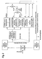
- FIG 2 a more detailed block diagram of a preferred embodiment of the proposed method, hereinafter referred to as "smartgreen3"-signal-reconstruction, is shown.
- the sensor data Via the central bus the sensor data is sent from the external memory in small packets to a small internal memory array in the reconstruction block.
- the [1Sx64Hx6V] array in Figure 2 containing 1 Signal (16 bits) and 64 Horizontal by 6 Vertical pixels (768 bytes) as an example, the raw sensor data can be randomly retrieved for reconstruction.
- a row of sensor data can be processed in multiples of (64-2*ho) pixels, where ho is the horizontal offset of the filter array.
- the (low) frequency transfer depends on the optical transfer of the camera. Whether the false color killer and the 2x2 post-filters are used or not also depends on the optical transfer.
- the R and B pixels are multiplied with the smartgreen parameters.
- the smartgreen parameters may e.g. be retrieved according to the method disclosed in WO 99/04555 or in EP 01 200 422.2 .
- This specific signal three aliasing free luminance signals are reconstructed: the contour signal, the white compensated luminance signal Yn and a low frequency luminance signal Ylf. The latter has about the same transfer characteristic as the reconstructed RGB signals.
- a third reason can be that it makes twice a [4Sx64Hx1V] internal memory superfluous, one in the reconstruction block for sending the four signals to the external memory and one in the processing block for retrieving them again.
- the [4Sx64Hx1V] internal memory stands for the storage of four (16 bit) signals of (64-2*ho) horizontal pixels of one vertical row, containing a total of 640 bytes when rounding to 64 pixels.
- the aliasing free contour is realized followed by the overshoot control processor which prevents over- and undershoots at lower frequencies.
- Two-dimensional sharpness improvement using a two-dimensional step transient signal is achieved by the realization of a two-dimensional detection signal which is suited for controlling overshoots.
- This so called step transient signal can be used for several overshoot (and undershoot) control methods, and results in a very attractive sharpness improvement without exaggerated and unnatural looking overshoots. It is allowed to add the contour and the (Yn-Ylf) signal to a single signal that is sent to the internal [4Sx64Hx1V] memory.
- the white compensated luminance signal is based on the calculation of the smartgreen parameters. Examples are shown in WO 99/04555 and EP 01 200 422.2 .
- the SmartGcntrlR and SmartGcntrlB parameters are referred to as: wbr and wbb respectively.
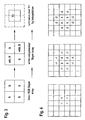
- Figure 3 shows that the red and blue pixels are multiplied with the smartgreen parameters. Next the four pixels are added together resulting in a white compensated luminance pixel Yn. The center of pixel Yn is shifted half a pixel to the right and to the bottom, considering the R pixel as the first one. The consequence is that all other signals that have to be reconstructed, i.e. red-green-blue and contour, should get the same center position as this Yn signal.
- the advantages of the white compensated luminance signal Yn are the very same as for the 5x5 aliasing free contour signal.
- An aliasing free contour- signal for RGB Bayer image sensors is based on a unique 5x5 parallel contour filter that, without the need for an optical low pass filter, has a zero throughput at the first RGB sample frequency. Its signal distortion is almost zero, resulting in a contour signal without visible artifacts.
- the so far known contour filters amplify the back folded and undesired frequencies outside the Nyquist domain of the sensor as well. This will lead to distortions and as a consequence a better visibility of the unwanted aliasing components in the picture.
- This unique 5x5 contour filter prevents those aliasing artifacts and moreover eliminates the green-green differences caused in the green channel of the image sensor. Particular advantages are:
- a slight disadvantage of the 2x2 white compensated luminance signal Yn may be that the resolution will be reduced when an optical low pass filter (OLPF) is applied.
- OLPF optical low pass filter
- 4x4 filters for the reconstruction of Yn.
- a Yn filter with heavier weights can be chosen.
- On the left hand side of Figure 6 the already described 2x2 Yn filter is shown.
- In the middle and on the right hand side two 4x4 Yn filters are shown. The right one is the 'heaviest' filter.
- They also can be applied for compensation of the transfer loss of the lens.
- the 4x4 Yn filters restore the green uniformity and eliminate the modulation in colored areas as well.
- the green uniformity restoration can be achieved by preventing green non-uniformity in the parallel contour signal of RGB Bayer image sensors which may be performed by developing a two-dimensional parallel contour filter that eliminates the green-green differences caused by the image sensor.
- Parallel contour processing for Bayer image sensors allows to use the green signal from the image sensor for generating a two-dimensional contour signal in parallel with the RGB color reconstruction. The advantage is that no extra row delays are needed as is the case with serial contour processing. As a rule one may say: The subtraction of neighbor diagonal filter coefficients should result in a zero contribution. This will average and, as a consequence, eliminate the green-green differences of the neighbor green pixels.
- the combinations of the negative coefficients always result in an addition of two green and a red a blue pixel, and also have the advantage of a zero transfer for the color modulation. It is to be noted that depending on the combination of the total optical transfer and the heaviness of an arbitrary 4x4 Yn filter, finally undesired over- and undershoots can occur.
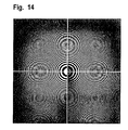
- the choice of the coefficients can only be done when the optical transfer is known, for example by shooting and processing a zone plate scene.
- the reconstruction method described in this preferred embodiment should be suited for cameras with an arbitrary optical low pass filter (OLPF) or with no OLPF at all.
- OLPF optical low pass filter
- the choice of an appropriate OLPF is not a simple matter. In most cases it is a compromise between the loss of sharpness and the acceptance of a certain amount of aliasing or preferably no aliasing at all. Relevant parameters are:
- a particular preferred RGB color reconstruction filter is explained: using a 3x3 array. Also a 5x5 array may be used for a RGB color reconstruction filter as described in a chapter 3.6 of the detailed description of a patent application WO2004/006183 . Both can be applied with (or without) a false color killer.
- the 4x4 and 6x6 aliasing free contour filters have a zero throughput at the first RGB sample frequency independent of the optical low pass transfer. Also the signal distortion is almost zero, as for the (Yn-Ylf) signal. This means that the aliasing free contour signal has no visible artifacts, because there is no back folding of undesired frequencies outside the Nyquist domain of the image sensor.
- the aliasing free contour signal has no visible artifacts, because there is no back folding of undesired frequencies outside the Nyquist domain of the image sensor.
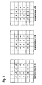
- 4x4 and 6 ⁇ 6 aliasing free contour filters possible, which all eliminate the green non-uniformity as well. In Figure 5 three 4x4 and in Figure 6 three 6x6 contour filters are shown.
- 6x4 filters are obtained with a sigmaContour of respectively 68, 52 and 84.
- the reason this is mentioned is because it offers the possibility of a smartgreen3-method with 4 rows or respectively 6 rows.
- the first 4x4 filter of Figure 5 has the very same weights as a first (Yn-Ylf) filter, just as the first 6x6 filter of Figure 46 is the same as a further (Yn-Ylf) filter.
- Yn-Ylf the filter weights of the (Yn-Ylf) and the contour filter, resulting in a further simplification of the smartgreen3-method design.
- the coring or a local noise reduction (LNR) or an overshoot control processing (OCP) may be performed on the total obtained contour signal, or on a part of it, as it is shown in Figure 7.
- the dashed part illustrates that a part of the contour signal, without LNR and OCP, can be applied as a (Yn-Ylf) signal. From a performance point of view there are no objections to do so. It is still possible to switch off the contour signal for demonstration purposes and, if switched on, to control its parameters. This possibility has same advantages with regard to a variety of applications.
- the only disadvantage of the block diagram of Figure 7 is that trying out another contour filter transfer, has consequences for the (Yn-Ylf) signal as well. Therefore, if a convenient adjustment and having some flexibility, is given priority it may be preferred in an alternative not to combine the (Yn-Ylf) filter and the contour filter.
- the choice of the (Yn-Ylf) filter is not too critical. Therefore, it does not make sense to describe how to combine its filter weights with the weights of the contour filter in order to obtain a single filter.
- contour filter type The choice of the contour filter type and the adjustment of the amount of contour depends on the personal taste at judging several pictures.
- the only directive that can be given is that it is rather logical to apply a 4x4 contour filter when a 3x3 color reconstruction has been chosen and a 6x6 contour filter in case of a 5x5 color reconstruction. Further, while adding contour, special attention should be paid to the desaturation of colored edges.
- OCP overshoot control processing
- LNR local noise reduction
- a method for a very specific two-dimensional contour filter can be applied.
- a contour with local noise reduction for digital electronic cameras is achieved by the realization of a very specific two-dimensional contour filter that is capable to reduce the amount of noise as well as the sharpness by means of a two-dimensional standard deviation function.
- An arbitrary contour filter, as applied with smartgreen3 and described above, preventing visible artifacts is also possible.
- smartgreen3 derivate which is referred to as smartgreen4. It consists of a 3x3 color reconstruction, does not use the (Yn-Ylf) signal and should preferably only be applied with two possible contour filters, a 5x5 or a 5x3 one. It is particular suitable for low cost applications.
- a very fast processing method with a very acceptable result, better than the smartgreen1/2 methods, is offered by the combination of, on the one hand, the 3x3 RGB reconstruction as described in a chapter 3.1 of the detailed description and, on the other hand, the 5x5 aliasing free contour filter as mentioned above.
- the mentioned unique 5x5 parallel contour filter has without the need for an optical low pass filter, a zero throughput at the first RGB sample frequency. Its signal distortion is almost zero, resulting in a contour signal without visible artifacts.
- the so far known contour filters amplify the back folded and undesired frequencies outside the Nyquist domain of the sensor as well. This will lead to distortions and as a consequence a better visibility of the unwanted aliasing components in the picture.
- This unique 5x5 contour filter prevents those aliasing artifacts and moreover eliminates the green-green-differences caused in the green channel of the image sensor.
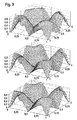
- the transfer characteristics of the RGB color-reconstruction-filters arc shown in Figures 10 and I and have better matching characteristics for a 3x3 green-reconstruction-filter as conventional filters. In the upper-left corner the filter weights are displayed.
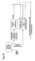
- the method is referred to as smartgreen4 and it offers all the mentioned advantages of both, reconstruction methods and also methods for the elimination of green-green differences. Because it is fast it can be applied for video signal reconstruction or, depending on the application, for still images as well. It is an interesting option to implement the possibility of this unique combination in a smartgreen3 chip design. Also for dedicated applications, requiring low power and a minimum of hardware, as for example with CMOS sensors, this combination seems to be a very advantageous embodiment. For dedicated high volume and low cost CMOS applications again fixed row delays can be applied in order to avoid external memory. In Figure 12 the basic block diagram for such an application is shown with an internal memory of [1 Sxrowx4V], i.e. four dedicated row delays. In Figure 13 a more detailed diagram of the reconstruction is shown.
- the false color detector acts with a smartgreen1 signal and applies respectively for the presence of green and for the absence of green. In case of the absence of green the detector should only be applied using a 5x5 array. Therefore here it has been chosen for the simplest version, using the smartgreen signal for the center row only.
- Four row delayed signals are offered to the 5x5 aliasing free contour reconstruction filter.
- the actual sensor signal contains the data of row 1. No local noise reduction, or overshoot control has been applied, however this is of course possible. Only a simple coring circuit reduces the noise.
- the 3x3 RGB reconstruction by use of filters of Figures 10 and 11 is shown combined with a very specific 5x3 parallel contour filter, which advantageously eliminates the green-green differences caused by the image sensor. Also for a further price reduction such a filter is very interesting because then only two instead of four row delays are needed. As can be seen the performance is less good. The sharpness has become asymmetrical due to the loss in the vertical direction and there are more interferences. Further more greenish aliasing occurs around the RGB sample frequency in the outer bottom-left corner.
- the 5x3 contour signal is shown (gain 1.0) which can be easily compared with the above lying 5x5 aliasing free contour. Most preferably, the contour signals also have been added to the RGB signals after the matrix and white balance processing.
- smartgreen3 is well suited for the reconstruction and processing of digital still images and of contiguous video pixels of sensors having a Bayer color filter array.
- smartgreen3 An interesting derivative of smartgreen3 is smartgreen4. By offering a low power consumption and a minimum of hardware smartgreen4 is suited for dedicated still and video applications.
Landscapes
- Engineering & Computer Science (AREA)
- Physics & Mathematics (AREA)
- Multimedia (AREA)
- Signal Processing (AREA)
- Spectroscopy & Molecular Physics (AREA)
- General Physics & Mathematics (AREA)
- Theoretical Computer Science (AREA)
- Color Television Image Signal Generators (AREA)
- Hardware Redundancy (AREA)
- Image Processing (AREA)
Claims (17)
- Verfahren zur Signalverarbeitung, wobei ein Sensorsignal eines Bildsensors als Eingangssignal geliefert wird und wobei das Eingangssignal in einem Filter rekonstruiert wird um ein Ausgangssignal zur Weiterverarbeitung zu bilden, wobei das Filter ein Farbrekonstruktionsfilter und ein Umrissrekonstruktionsfilter umfasst, wobei- das Eingangssignal eine Anzahl Pixel enthält, und ein Pixel einen Farbwert liefert, der wenigstens einer der Farben Rot, Grün oder Blau zugeordnet ist,wobei das Verfahren die nachfolgenden Verfahrensschritte umfasst:- das Anwenden des Rekonstruktionsfilters auf eine Anordnung von Pixeln einer vorbestimmten Anordnungsgröße mit einer Anzahl Pixel, wobei wenigstens ein Pixel der vielen Pixel durch ein Rotpixel gebildet wird, das der Farbe Rot zugeordnet ist, wenigstens ein Pixel der vielen Pixel durch ein Blaupixel gebildet wird, das der Farbe Blau zugeordnet ist, und wenigstens ein Pixel der vielen Pixel durch ein Grünpixel gebildet wird, das der Farbe Grün zugeordnet ist,- das Gewichten des Rot- und/oder Blaupixels durch einen Grünparameter, und- das Anwenden einer Umrissrekonstruktionsfilters, das die Summierung der Pixel der Anordnung nach der Gewichtung durch den Grünparameter zu einem einzigen Ausgangspixel, und- das Zentrieren des Ausgangspixels in der Anordnung, und gekennzeichnet durch- das Anwenden des Umrissrekonstruktionsfilters parallel zu der Anwendung des Farbrekonstruktionsfilters auf die Pixel.
- Verfahren nach Anspruch 1, das Folgendes umfasst: das Multiplizieren von Pixeln der Anordnung mit Umrissrekonstruktionsfilterkoeffizienten nach der Gewichtung durch den Grünparameter und Summierung der multiplizierten Pixel zu dem Ausgangspixel.
- Verfahren nach Anspruch 1, das weiterhin Folgendes umfasst: das Anwenden eines Leuchtdichterekonstruktionsfilters mit einer Summierung der Pixel der Anordnung nach Gewichtung durch den Grünparameter zu einem einzigen Leuchtdichterekonstruktionsausgangspixel.
- Verfahren nach Anspruch 1, das Folgendes umfasst: das Multiplizieren von Pixeln der Anordnung mit Leuchtdichterekonstruktionsfilterkoeffizienten nach der Gewichtung durch den Grünparameter und Summierung der multiplizierten Pixel zu dem Leuchtdichterekonstruktionsausgangspixel.
- Verfahren nach Anspruch 3, gekennzeichnet durch die Kombination des Leuchtdichterekonstruktionsfilters und eines Tiefpassfilters zu einem einzigen Filter.
- Verfahren nach Anspruch 1, gekennzeichnet durch Anwendung des Farbrekonstruktionsfilters auf die Anordnungsgröße von 3*3 oder 5*5.
- Verfahren nach Anspruch 3, gekennzeichnet durch Anwendung eines Nachfilters der Anordnungsgröße von 2*2 nach einem Falschfarbfilters zum Positionieren eines zentralen Ausgangspixels einer vorbestimmten kleinen Anordnung von Grünpixeln in Phase zu einem Weißpixel, das gegenüber derselben Anordnung zentriert ist, auf die das Leuchtdichterekonstruktionsfilter angewandt worden ist.
- Verfahren nach Anspruch 3, gekennzeichnet durch das Umrissrekonstruktionsfilter , parallel zu dem Leuchtdichterekonstruktionsfilter und durch nachträgliche Addierung der rekonstruierten Signale.
- Verfahren nach Anspruch 1, gekennzeichnet durch Anwendung des Umrissrekonstruktionsfilters auf eine Anordnungsgröße, die größer ist als die Größe einer Anordnung, auf die das Farbrekonstruktionsfilter angewandt wird.
- Verfahren nach Anspruch 1, dadurch gekennzeichnet, dass die Anordnungsgröße 5*5, 4*4 oder 6*6 beträgt.
- Verfahren nach Anspruch 3, gekennzeichnet durch das Anbieten mehrerer Farbrekonstruktionsfilter zur Anwendung, insbesondere durch Anwendung eines 3*3 Farbrekonstruktionsfilters im Falle eines 4*4 Leuchtdichterekonstruktionsfilters und/oder durch Anwendung eines 5*5 Farbrekonstruktionsfilters im Falle eines 6*6 Leuchtdichterekonstruktionsfilters.
- Verfahren nach Anspruch 1, gekennzeichnet durch das Anbieten mehrerer Umrissrekonstruktionsfilter zur Anwendung, insbesondere durch Anwendung eines 4*4 Umrissrekonstruktionsfilters im Falle eines 3*3 Farbrekonstruktionsfilters oder durch Anwendung eines 6*6 Umrissrekonstruktionsfilters im Falle eines 5*5 Farbrekonstruktionsfilters.
- Verfahren nach Anspruch 1, gekennzeichnet durch Anwendung eines 3*3 Farbrekonstruktionsfilters in Kombination mit einem 5*5 Farbrekonstruktionsfilter, insbesondere durch nachträgliche Addierung eines farbrekonstruierten und eines umrissrekonstruierten Signals zur Weiterverarbeitung.
- Anordnung zur Signalverarbeitung, die insbesondere zum Durchführen des Verfahrens nach Anspruch 1 vorgesehen ist, wobei diese Anordnung Folgendes umfasst:- einen Bildsensor zum Schaffen eines Sensorsignals als Eingangssignal und- ein Filter zum Rekonstruieren des Eingangssignals zum Bilden eines Ausgangssignals zur Weiterverarbeitung, wobei das Filter ein Farbrekonstruktionsfilter und ein Umrissrekonstruktionsfilter umfasst, wobei- das Eingangssignal eine Anzahl Pixel umfasst, und ein Pixel einen Farbwert schafft, der wenigstens einer Farbe der Farben Rot, Grün oder Blau zugeordnet ist, wobei- das Rekonstruktionsfilter dazu vorgesehen ist, auf eine Anordnung von Pixeln vorbestimmter Anordnungsgröße mit einer Anzahl Pixel angewandt zu werden, wobei wenigstens ein Pixel der vielen Pixel durch ein Rotpixel gebildet wird, das der Farbe Rot zugeordnet ist, wenigstens ein Pixel der vielen Pixel durch ein Blaupixel gebildet wird, das der Farbe Blau zugeordnet ist, und wenigstens ein Pixel der vielen Pixel durch ein Grünpixel gebildet wird, das der Farbe Grün zugeordnet ist und wobei die Anordnung weiterhin Folgendes umfasst:- Mittel zum Gewichten des Rot- und/oder des Blaupixels durch einen Grünparameter,- das Umrissrekonstruktionsfilter mit Mitteln zum Summieren der Pixel der Anordnung nach der Gewichtung durch den Grünparameter zu einem einzigen Ausgangspixel,- Mittel zum Zentrieren des Ausgangspixels in der Anordnung und- Mittel zur parallelen Anwendung des Umrissrekonstruktionsfilters und des Farbrekonstruktionsfilters, wobei das Farbrekonstruktionsfilter auf Pixel aus der Anordnung angewandt wird.
- Computerprogrammprodukt, speicherbar auf einem Medium, das von einem Rechensystem ausgelesen werden kann, insbesondere ein Rechensystem einer Kamera, mit einem Softwarecodeteil, der das Rechensystem veranlasst das Verfahren nach Anspruch 1 durchzuführen, wenn das Produkt in dem Rechensystem durchgeführt wird, insbesondere wenn in einem Rechensystem einer Kamera durchgeführt.
- Rechensystem und/oder Halbleiteranordnung, insbesondere ein Rechensystem einer Kamera zum Durchführen und/oder Speichern eines Computerprogrammproduktes nach Anspruch 15.
- Kamera mit einem optischen System, einem Bildsensor und einem Rechensystem nach Anspruch 16.
Priority Applications (1)
| Application Number | Priority Date | Filing Date | Title |
|---|---|---|---|
| EP03735896A EP1522047B1 (de) | 2002-07-04 | 2003-06-24 | Methode und apparat zur signalverarbeitung, computerprogrammprodukt, computersystem und kamera |
Applications Claiming Priority (4)
| Application Number | Priority Date | Filing Date | Title |
|---|---|---|---|
| EP02077691 | 2002-07-04 | ||
| EP02077691 | 2002-07-04 | ||
| PCT/IB2003/002651 WO2004006182A1 (en) | 2002-07-04 | 2003-06-24 | Method and apparatus for signal processing, computer program product, computing system and camera |
| EP03735896A EP1522047B1 (de) | 2002-07-04 | 2003-06-24 | Methode und apparat zur signalverarbeitung, computerprogrammprodukt, computersystem und kamera |
Publications (2)
| Publication Number | Publication Date |
|---|---|
| EP1522047A1 EP1522047A1 (de) | 2005-04-13 |
| EP1522047B1 true EP1522047B1 (de) | 2008-01-16 |
Family
ID=30011157
Family Applications (1)
| Application Number | Title | Priority Date | Filing Date |
|---|---|---|---|
| EP03735896A Expired - Lifetime EP1522047B1 (de) | 2002-07-04 | 2003-06-24 | Methode und apparat zur signalverarbeitung, computerprogrammprodukt, computersystem und kamera |
Country Status (9)
| Country | Link |
|---|---|
| US (1) | US20050226481A1 (de) |
| EP (1) | EP1522047B1 (de) |
| JP (1) | JP2005532002A (de) |
| KR (1) | KR20050014916A (de) |
| CN (1) | CN1666230A (de) |
| AT (1) | ATE384311T1 (de) |
| AU (1) | AU2003236984A1 (de) |
| DE (1) | DE60318709T2 (de) |
| WO (1) | WO2004006182A1 (de) |
Families Citing this family (1)
| Publication number | Priority date | Publication date | Assignee | Title |
|---|---|---|---|---|
| US8026954B2 (en) * | 2007-04-10 | 2011-09-27 | Aricent Inc. | System and computer-readable medium for automatic white balancing |
Family Cites Families (9)
| Publication number | Priority date | Publication date | Assignee | Title |
|---|---|---|---|---|
| JP4380805B2 (ja) * | 1997-07-15 | 2009-12-09 | エヌエックスピー ビー ヴィ | 色サンプルの補間方法、装置及びカメラ |
| US6507364B1 (en) * | 1998-03-13 | 2003-01-14 | Pictos Technologies, Inc. | Edge-dependent interpolation method for color reconstruction in image processing devices |
| US6888568B1 (en) * | 1999-08-19 | 2005-05-03 | Dialog Semiconductor Gmbh | Method and apparatus for controlling pixel sensor elements |
| US6791609B2 (en) * | 1999-12-20 | 2004-09-14 | Texas Instruments Incorporated | Digital still camera system and method |
| JP3706789B2 (ja) * | 2000-05-12 | 2005-10-19 | キヤノン株式会社 | 信号処理装置及び信号処理方法 |
| JP4055927B2 (ja) * | 2000-08-25 | 2008-03-05 | シャープ株式会社 | 画像処理装置およびデジタルカメラ |
| CN1294534C (zh) * | 2001-02-06 | 2007-01-10 | 皇家菲利浦电子有限公司 | 防止图像传感器的绿色不一致 |
| DE60318710D1 (de) * | 2002-07-04 | 2008-03-06 | Koninkl Philips Electronics Nv | Methode und apparat zur signalverarbeitung, computerprogrammprodukt, computersystem und kamera |
| ATE426869T1 (de) * | 2002-07-04 | 2009-04-15 | Koninkl Philips Electronics Nv | Methode und apparat zur signalverarbeitung, computerprogrammprodukt, computersystem und kamera |
-
2003
- 2003-06-24 JP JP2004519062A patent/JP2005532002A/ja not_active Withdrawn
- 2003-06-24 WO PCT/IB2003/002651 patent/WO2004006182A1/en not_active Ceased
- 2003-06-24 CN CN038159198A patent/CN1666230A/zh active Pending
- 2003-06-24 AT AT03735896T patent/ATE384311T1/de not_active IP Right Cessation
- 2003-06-24 US US10/519,063 patent/US20050226481A1/en not_active Abandoned
- 2003-06-24 EP EP03735896A patent/EP1522047B1/de not_active Expired - Lifetime
- 2003-06-24 AU AU2003236984A patent/AU2003236984A1/en not_active Abandoned
- 2003-06-24 KR KR10-2005-7000039A patent/KR20050014916A/ko not_active Ceased
- 2003-06-24 DE DE60318709T patent/DE60318709T2/de not_active Expired - Lifetime
Also Published As
| Publication number | Publication date |
|---|---|
| EP1522047A1 (de) | 2005-04-13 |
| WO2004006182A1 (en) | 2004-01-15 |
| ATE384311T1 (de) | 2008-02-15 |
| DE60318709D1 (de) | 2008-03-06 |
| DE60318709T2 (de) | 2008-08-28 |
| US20050226481A1 (en) | 2005-10-13 |
| JP2005532002A (ja) | 2005-10-20 |
| AU2003236984A1 (en) | 2004-01-23 |
| KR20050014916A (ko) | 2005-02-07 |
| CN1666230A (zh) | 2005-09-07 |
Similar Documents
| Publication | Publication Date | Title |
|---|---|---|
| US8115840B2 (en) | Image enhancement in the mosaic domain | |
| US7907791B2 (en) | Processing of mosaic images | |
| EP2130176B1 (de) | Kantenabbildung mit schwarzweisspixeln | |
| USRE42555E1 (en) | Merged pipeline for color interpolation and edge enhancement of digital images | |
| EP2089848B1 (de) | Rauschunterdrückung für schwarzweiss- und farbbilder | |
| EP1395041A2 (de) | Farbkorrektur von Bildern | |
| US7072509B2 (en) | Electronic image color plane reconstruction | |
| WO2008121272A2 (en) | Edge mapping incorporating panchromatic pixels | |
| WO2002063888A1 (en) | Green reconstruction for image sensors | |
| US7573515B2 (en) | Method and apparatus for processing a sensor signal having a plurality of pixels from an image sensor, computer program product, computing system and camera | |
| WO2009098619A2 (en) | Method and device for reconstructing a color image | |
| EP1522048B1 (de) | Methode und apparat zur signalverarbeitung, computerprogrammprodukt, computersystem und kamera | |
| US20050226481A1 (en) | Method and apparatus for signal processing, computer program product, computing system and camera | |
| Adams et al. | Noise cleaning digital camera images to improve color fidelity capabilities | |
| KR20050016750A (ko) | 신호 처리 방법 및 장치, 컴퓨터 프로그램 제품, 컴퓨터시스템, 반도체 장치, 및 카메라 | |
| KR20050016978A (ko) | 신호 처리 방법 및 장치, 컴퓨터 프로그램 제품, 컴퓨팅시스템 및 카메라 | |
| IL191290A (en) | Image enhancement in the mosaic domain |
Legal Events
| Date | Code | Title | Description |
|---|---|---|---|
| PUAI | Public reference made under article 153(3) epc to a published international application that has entered the european phase |
Free format text: ORIGINAL CODE: 0009012 |
|
| 17P | Request for examination filed |
Effective date: 20050204 |
|
| AK | Designated contracting states |
Kind code of ref document: A1 Designated state(s): AT BE BG CH CY CZ DE DK EE ES FI FR GB GR HU IE IT LI LU MC NL PT RO SE SI SK TR |
|
| AX | Request for extension of the european patent |
Extension state: AL LT LV MK |
|
| DAX | Request for extension of the european patent (deleted) | ||
| 17Q | First examination report despatched |
Effective date: 20061201 |
|
| GRAP | Despatch of communication of intention to grant a patent |
Free format text: ORIGINAL CODE: EPIDOSNIGR1 |
|
| GRAS | Grant fee paid |
Free format text: ORIGINAL CODE: EPIDOSNIGR3 |
|
| GRAA | (expected) grant |
Free format text: ORIGINAL CODE: 0009210 |
|
| AK | Designated contracting states |
Kind code of ref document: B1 Designated state(s): AT BE BG CH CY CZ DE DK EE ES FI FR GB GR HU IE IT LI LU MC NL PT RO SE SI SK TR |
|
| REG | Reference to a national code |
Ref country code: GB Ref legal event code: FG4D |
|
| REG | Reference to a national code |
Ref country code: CH Ref legal event code: EP |
|
| REG | Reference to a national code |
Ref country code: IE Ref legal event code: FG4D |
|
| REF | Corresponds to: |
Ref document number: 60318709 Country of ref document: DE Date of ref document: 20080306 Kind code of ref document: P |
|
| PG25 | Lapsed in a contracting state [announced via postgrant information from national office to epo] |
Ref country code: NL Free format text: LAPSE BECAUSE OF FAILURE TO SUBMIT A TRANSLATION OF THE DESCRIPTION OR TO PAY THE FEE WITHIN THE PRESCRIBED TIME-LIMIT Effective date: 20080116 |
|
| NLV1 | Nl: lapsed or annulled due to failure to fulfill the requirements of art. 29p and 29m of the patents act | ||
| PG25 | Lapsed in a contracting state [announced via postgrant information from national office to epo] |
Ref country code: FI Free format text: LAPSE BECAUSE OF FAILURE TO SUBMIT A TRANSLATION OF THE DESCRIPTION OR TO PAY THE FEE WITHIN THE PRESCRIBED TIME-LIMIT Effective date: 20080116 Ref country code: LI Free format text: LAPSE BECAUSE OF FAILURE TO SUBMIT A TRANSLATION OF THE DESCRIPTION OR TO PAY THE FEE WITHIN THE PRESCRIBED TIME-LIMIT Effective date: 20080116 Ref country code: ES Free format text: LAPSE BECAUSE OF FAILURE TO SUBMIT A TRANSLATION OF THE DESCRIPTION OR TO PAY THE FEE WITHIN THE PRESCRIBED TIME-LIMIT Effective date: 20080427 Ref country code: CH Free format text: LAPSE BECAUSE OF FAILURE TO SUBMIT A TRANSLATION OF THE DESCRIPTION OR TO PAY THE FEE WITHIN THE PRESCRIBED TIME-LIMIT Effective date: 20080116 |
|
| REG | Reference to a national code |
Ref country code: CH Ref legal event code: PL |
|
| PG25 | Lapsed in a contracting state [announced via postgrant information from national office to epo] |
Ref country code: BG Free format text: LAPSE BECAUSE OF FAILURE TO SUBMIT A TRANSLATION OF THE DESCRIPTION OR TO PAY THE FEE WITHIN THE PRESCRIBED TIME-LIMIT Effective date: 20080416 Ref country code: AT Free format text: LAPSE BECAUSE OF FAILURE TO SUBMIT A TRANSLATION OF THE DESCRIPTION OR TO PAY THE FEE WITHIN THE PRESCRIBED TIME-LIMIT Effective date: 20080116 |
|
| ET | Fr: translation filed | ||
| PG25 | Lapsed in a contracting state [announced via postgrant information from national office to epo] |
Ref country code: BE Free format text: LAPSE BECAUSE OF FAILURE TO SUBMIT A TRANSLATION OF THE DESCRIPTION OR TO PAY THE FEE WITHIN THE PRESCRIBED TIME-LIMIT Effective date: 20080116 Ref country code: SI Free format text: LAPSE BECAUSE OF FAILURE TO SUBMIT A TRANSLATION OF THE DESCRIPTION OR TO PAY THE FEE WITHIN THE PRESCRIBED TIME-LIMIT Effective date: 20080116 Ref country code: PT Free format text: LAPSE BECAUSE OF FAILURE TO SUBMIT A TRANSLATION OF THE DESCRIPTION OR TO PAY THE FEE WITHIN THE PRESCRIBED TIME-LIMIT Effective date: 20080616 |
|
| PG25 | Lapsed in a contracting state [announced via postgrant information from national office to epo] |
Ref country code: CZ Free format text: LAPSE BECAUSE OF FAILURE TO SUBMIT A TRANSLATION OF THE DESCRIPTION OR TO PAY THE FEE WITHIN THE PRESCRIBED TIME-LIMIT Effective date: 20080116 Ref country code: DK Free format text: LAPSE BECAUSE OF FAILURE TO SUBMIT A TRANSLATION OF THE DESCRIPTION OR TO PAY THE FEE WITHIN THE PRESCRIBED TIME-LIMIT Effective date: 20080116 Ref country code: SK Free format text: LAPSE BECAUSE OF FAILURE TO SUBMIT A TRANSLATION OF THE DESCRIPTION OR TO PAY THE FEE WITHIN THE PRESCRIBED TIME-LIMIT Effective date: 20080116 Ref country code: SE Free format text: LAPSE BECAUSE OF FAILURE TO SUBMIT A TRANSLATION OF THE DESCRIPTION OR TO PAY THE FEE WITHIN THE PRESCRIBED TIME-LIMIT Effective date: 20080416 |
|
| PLBE | No opposition filed within time limit |
Free format text: ORIGINAL CODE: 0009261 |
|
| STAA | Information on the status of an ep patent application or granted ep patent |
Free format text: STATUS: NO OPPOSITION FILED WITHIN TIME LIMIT |
|
| PG25 | Lapsed in a contracting state [announced via postgrant information from national office to epo] |
Ref country code: RO Free format text: LAPSE BECAUSE OF FAILURE TO SUBMIT A TRANSLATION OF THE DESCRIPTION OR TO PAY THE FEE WITHIN THE PRESCRIBED TIME-LIMIT Effective date: 20080116 |
|
| PGFP | Annual fee paid to national office [announced via postgrant information from national office to epo] |
Ref country code: FR Payment date: 20080626 Year of fee payment: 6 |
|
| 26N | No opposition filed |
Effective date: 20081017 |
|
| PG25 | Lapsed in a contracting state [announced via postgrant information from national office to epo] |
Ref country code: MC Free format text: LAPSE BECAUSE OF NON-PAYMENT OF DUE FEES Effective date: 20080630 |
|
| REG | Reference to a national code |
Ref country code: GB Ref legal event code: 732E Free format text: REGISTERED BETWEEN 20090312 AND 20090318 |
|
| PG25 | Lapsed in a contracting state [announced via postgrant information from national office to epo] |
Ref country code: IE Free format text: LAPSE BECAUSE OF NON-PAYMENT OF DUE FEES Effective date: 20080624 Ref country code: EE Free format text: LAPSE BECAUSE OF FAILURE TO SUBMIT A TRANSLATION OF THE DESCRIPTION OR TO PAY THE FEE WITHIN THE PRESCRIBED TIME-LIMIT Effective date: 20080116 |
|
| PG25 | Lapsed in a contracting state [announced via postgrant information from national office to epo] |
Ref country code: CY Free format text: LAPSE BECAUSE OF FAILURE TO SUBMIT A TRANSLATION OF THE DESCRIPTION OR TO PAY THE FEE WITHIN THE PRESCRIBED TIME-LIMIT Effective date: 20080116 |
|
| PG25 | Lapsed in a contracting state [announced via postgrant information from national office to epo] |
Ref country code: IT Free format text: LAPSE BECAUSE OF FAILURE TO SUBMIT A TRANSLATION OF THE DESCRIPTION OR TO PAY THE FEE WITHIN THE PRESCRIBED TIME-LIMIT Effective date: 20080116 |
|
| REG | Reference to a national code |
Ref country code: FR Ref legal event code: ST Effective date: 20100226 |
|
| PG25 | Lapsed in a contracting state [announced via postgrant information from national office to epo] |
Ref country code: FR Free format text: LAPSE BECAUSE OF NON-PAYMENT OF DUE FEES Effective date: 20090630 |
|
| PG25 | Lapsed in a contracting state [announced via postgrant information from national office to epo] |
Ref country code: LU Free format text: LAPSE BECAUSE OF NON-PAYMENT OF DUE FEES Effective date: 20080624 Ref country code: HU Free format text: LAPSE BECAUSE OF FAILURE TO SUBMIT A TRANSLATION OF THE DESCRIPTION OR TO PAY THE FEE WITHIN THE PRESCRIBED TIME-LIMIT Effective date: 20080717 |
|
| PG25 | Lapsed in a contracting state [announced via postgrant information from national office to epo] |
Ref country code: TR Free format text: LAPSE BECAUSE OF FAILURE TO SUBMIT A TRANSLATION OF THE DESCRIPTION OR TO PAY THE FEE WITHIN THE PRESCRIBED TIME-LIMIT Effective date: 20080116 |
|
| PG25 | Lapsed in a contracting state [announced via postgrant information from national office to epo] |
Ref country code: GR Free format text: LAPSE BECAUSE OF FAILURE TO SUBMIT A TRANSLATION OF THE DESCRIPTION OR TO PAY THE FEE WITHIN THE PRESCRIBED TIME-LIMIT Effective date: 20080417 |
|
| REG | Reference to a national code |
Ref country code: GB Ref legal event code: 732E Free format text: REGISTERED BETWEEN 20120628 AND 20120704 |
|
| REG | Reference to a national code |
Ref country code: DE Ref legal event code: R081 Ref document number: 60318709 Country of ref document: DE Owner name: PENDRAGON WIRELESS LLC (A NEVADA MANAGED LIMIT, US Free format text: FORMER OWNER: IPG ELECTRONICS 503 LTD., ST. PETER PORT, GB Effective date: 20121213 Ref country code: DE Ref legal event code: R082 Ref document number: 60318709 Country of ref document: DE Representative=s name: PATENTANWAELTE BRESSEL UND PARTNER, DE Effective date: 20121213 Ref country code: DE Ref legal event code: R081 Ref document number: 60318709 Country of ref document: DE Owner name: PENDRAGON WIRELESS LLC (A NEVADA MANAGED LIMIT, US Free format text: FORMER OWNER: IPG ELECTRONICS 503 LTD., ST. PETER PORT, GUERNSEY, GB Effective date: 20121213 Ref country code: DE Ref legal event code: R082 Ref document number: 60318709 Country of ref document: DE Representative=s name: PATENTANWAELTE BRESSEL UND PARTNER MBB, DE Effective date: 20121213 |
|
| PGFP | Annual fee paid to national office [announced via postgrant information from national office to epo] |
Ref country code: DE Payment date: 20130620 Year of fee payment: 11 Ref country code: GB Payment date: 20130619 Year of fee payment: 11 |
|
| REG | Reference to a national code |
Ref country code: DE Ref legal event code: R119 Ref document number: 60318709 Country of ref document: DE |
|
| GBPC | Gb: european patent ceased through non-payment of renewal fee |
Effective date: 20140624 |
|
| REG | Reference to a national code |
Ref country code: DE Ref legal event code: R119 Ref document number: 60318709 Country of ref document: DE Effective date: 20150101 |
|
| PG25 | Lapsed in a contracting state [announced via postgrant information from national office to epo] |
Ref country code: DE Free format text: LAPSE BECAUSE OF NON-PAYMENT OF DUE FEES Effective date: 20150101 |
|
| PG25 | Lapsed in a contracting state [announced via postgrant information from national office to epo] |
Ref country code: GB Free format text: LAPSE BECAUSE OF NON-PAYMENT OF DUE FEES Effective date: 20140624 |