EP1521671B1 - Guiding of a cut-open parison - Google Patents
Guiding of a cut-open parison Download PDFInfo
- Publication number
- EP1521671B1 EP1521671B1 EP03763757A EP03763757A EP1521671B1 EP 1521671 B1 EP1521671 B1 EP 1521671B1 EP 03763757 A EP03763757 A EP 03763757A EP 03763757 A EP03763757 A EP 03763757A EP 1521671 B1 EP1521671 B1 EP 1521671B1
- Authority
- EP
- European Patent Office
- Prior art keywords
- partitioning
- parison
- plastic parison
- plastic
- drive
- Prior art date
- Legal status (The legal status is an assumption and is not a legal conclusion. Google has not performed a legal analysis and makes no representation as to the accuracy of the status listed.)
- Expired - Lifetime
Links
- 239000004033 plastic Substances 0.000 claims abstract description 39
- 238000000638 solvent extraction Methods 0.000 claims abstract description 26
- 238000005520 cutting process Methods 0.000 claims description 29
- 238000001125 extrusion Methods 0.000 claims description 16
- 238000000926 separation method Methods 0.000 claims description 7
- 238000000576 coating method Methods 0.000 claims description 6
- 239000011248 coating agent Substances 0.000 claims description 4
- 125000006850 spacer group Chemical group 0.000 claims description 2
- 238000004519 manufacturing process Methods 0.000 abstract description 3
- 238000000034 method Methods 0.000 description 17
- 239000011265 semifinished product Substances 0.000 description 12
- 230000008569 process Effects 0.000 description 9
- 239000000047 product Substances 0.000 description 9
- 238000000071 blow moulding Methods 0.000 description 7
- 239000010410 layer Substances 0.000 description 3
- 229920000642 polymer Polymers 0.000 description 3
- 238000003856 thermoforming Methods 0.000 description 3
- 230000004888 barrier function Effects 0.000 description 2
- 230000008901 benefit Effects 0.000 description 2
- 238000010586 diagram Methods 0.000 description 2
- 230000000694 effects Effects 0.000 description 2
- 230000007246 mechanism Effects 0.000 description 2
- 230000032258 transport Effects 0.000 description 2
- 238000011144 upstream manufacturing Methods 0.000 description 2
- 238000003466 welding Methods 0.000 description 2
- 229910000831 Steel Inorganic materials 0.000 description 1
- 230000006835 compression Effects 0.000 description 1
- 238000007906 compression Methods 0.000 description 1
- 238000003682 fluorination reaction Methods 0.000 description 1
- 238000009434 installation Methods 0.000 description 1
- 239000000463 material Substances 0.000 description 1
- 239000002184 metal Substances 0.000 description 1
- 239000000203 mixture Substances 0.000 description 1
- 238000010422 painting Methods 0.000 description 1
- 238000005192 partition Methods 0.000 description 1
- 239000002861 polymer material Substances 0.000 description 1
- -1 polytetrafluoroethylene Polymers 0.000 description 1
- 229920001343 polytetrafluoroethylene Polymers 0.000 description 1
- 239000004810 polytetrafluoroethylene Substances 0.000 description 1
- 230000001737 promoting effect Effects 0.000 description 1
- 239000002356 single layer Substances 0.000 description 1
- 238000001228 spectrum Methods 0.000 description 1
- 239000010959 steel Substances 0.000 description 1
- 229920001169 thermoplastic Polymers 0.000 description 1
- 239000004416 thermosoftening plastic Substances 0.000 description 1
Images

Classifications
-
- B—PERFORMING OPERATIONS; TRANSPORTING
- B29—WORKING OF PLASTICS; WORKING OF SUBSTANCES IN A PLASTIC STATE IN GENERAL
- B29C—SHAPING OR JOINING OF PLASTICS; SHAPING OF MATERIAL IN A PLASTIC STATE, NOT OTHERWISE PROVIDED FOR; AFTER-TREATMENT OF THE SHAPED PRODUCTS, e.g. REPAIRING
- B29C69/00—Combinations of shaping techniques not provided for in a single one of main groups B29C39/00 - B29C67/00, e.g. associations of moulding and joining techniques; Apparatus therefore
-
- B—PERFORMING OPERATIONS; TRANSPORTING
- B29—WORKING OF PLASTICS; WORKING OF SUBSTANCES IN A PLASTIC STATE IN GENERAL
- B29C—SHAPING OR JOINING OF PLASTICS; SHAPING OF MATERIAL IN A PLASTIC STATE, NOT OTHERWISE PROVIDED FOR; AFTER-TREATMENT OF THE SHAPED PRODUCTS, e.g. REPAIRING
- B29C37/00—Component parts, details, accessories or auxiliary operations, not covered by group B29C33/00 or B29C35/00
-
- B—PERFORMING OPERATIONS; TRANSPORTING
- B29—WORKING OF PLASTICS; WORKING OF SUBSTANCES IN A PLASTIC STATE IN GENERAL
- B29C—SHAPING OR JOINING OF PLASTICS; SHAPING OF MATERIAL IN A PLASTIC STATE, NOT OTHERWISE PROVIDED FOR; AFTER-TREATMENT OF THE SHAPED PRODUCTS, e.g. REPAIRING
- B29C48/00—Extrusion moulding, i.e. expressing the moulding material through a die or nozzle which imparts the desired form; Apparatus therefor
- B29C48/001—Combinations of extrusion moulding with other shaping operations
- B29C48/0022—Combinations of extrusion moulding with other shaping operations combined with cutting
-
- B—PERFORMING OPERATIONS; TRANSPORTING
- B29—WORKING OF PLASTICS; WORKING OF SUBSTANCES IN A PLASTIC STATE IN GENERAL
- B29C—SHAPING OR JOINING OF PLASTICS; SHAPING OF MATERIAL IN A PLASTIC STATE, NOT OTHERWISE PROVIDED FOR; AFTER-TREATMENT OF THE SHAPED PRODUCTS, e.g. REPAIRING
- B29C49/00—Blow-moulding, i.e. blowing a preform or parison to a desired shape within a mould; Apparatus therefor
- B29C49/02—Combined blow-moulding and manufacture of the preform or the parison
- B29C49/04—Extrusion blow-moulding
-
- B—PERFORMING OPERATIONS; TRANSPORTING
- B29—WORKING OF PLASTICS; WORKING OF SUBSTANCES IN A PLASTIC STATE IN GENERAL
- B29C—SHAPING OR JOINING OF PLASTICS; SHAPING OF MATERIAL IN A PLASTIC STATE, NOT OTHERWISE PROVIDED FOR; AFTER-TREATMENT OF THE SHAPED PRODUCTS, e.g. REPAIRING
- B29C49/00—Blow-moulding, i.e. blowing a preform or parison to a desired shape within a mould; Apparatus therefor
- B29C49/02—Combined blow-moulding and manufacture of the preform or the parison
- B29C49/06905—Using combined techniques for making the preform
- B29C49/0691—Using combined techniques for making the preform using sheet like material, e.g. sheet blow-moulding from joined sheets
-
- B—PERFORMING OPERATIONS; TRANSPORTING
- B29—WORKING OF PLASTICS; WORKING OF SUBSTANCES IN A PLASTIC STATE IN GENERAL
- B29C—SHAPING OR JOINING OF PLASTICS; SHAPING OF MATERIAL IN A PLASTIC STATE, NOT OTHERWISE PROVIDED FOR; AFTER-TREATMENT OF THE SHAPED PRODUCTS, e.g. REPAIRING
- B29C49/00—Blow-moulding, i.e. blowing a preform or parison to a desired shape within a mould; Apparatus therefor
- B29C49/071—Preforms or parisons characterised by their configuration, e.g. geometry, dimensions or physical properties
-
- B—PERFORMING OPERATIONS; TRANSPORTING
- B29—WORKING OF PLASTICS; WORKING OF SUBSTANCES IN A PLASTIC STATE IN GENERAL
- B29C—SHAPING OR JOINING OF PLASTICS; SHAPING OF MATERIAL IN A PLASTIC STATE, NOT OTHERWISE PROVIDED FOR; AFTER-TREATMENT OF THE SHAPED PRODUCTS, e.g. REPAIRING
- B29C49/00—Blow-moulding, i.e. blowing a preform or parison to a desired shape within a mould; Apparatus therefor
- B29C49/42—Component parts, details or accessories; Auxiliary operations
- B29C49/42394—Providing specific wall thickness
-
- B—PERFORMING OPERATIONS; TRANSPORTING
- B29—WORKING OF PLASTICS; WORKING OF SUBSTANCES IN A PLASTIC STATE IN GENERAL
- B29C—SHAPING OR JOINING OF PLASTICS; SHAPING OF MATERIAL IN A PLASTIC STATE, NOT OTHERWISE PROVIDED FOR; AFTER-TREATMENT OF THE SHAPED PRODUCTS, e.g. REPAIRING
- B29C49/00—Blow-moulding, i.e. blowing a preform or parison to a desired shape within a mould; Apparatus therefor
- B29C49/42—Component parts, details or accessories; Auxiliary operations
- B29C49/4242—Means for deforming the parison prior to the blowing operation
- B29C49/4247—Means for deforming the parison prior to the blowing operation using spreading or extending means
-
- B—PERFORMING OPERATIONS; TRANSPORTING
- B29—WORKING OF PLASTICS; WORKING OF SUBSTANCES IN A PLASTIC STATE IN GENERAL
- B29C—SHAPING OR JOINING OF PLASTICS; SHAPING OF MATERIAL IN A PLASTIC STATE, NOT OTHERWISE PROVIDED FOR; AFTER-TREATMENT OF THE SHAPED PRODUCTS, e.g. REPAIRING
- B29C53/00—Shaping by bending, folding, twisting, straightening or flattening; Apparatus therefor
- B29C53/02—Bending or folding
- B29C53/10—Bending or folding of blown tubular films, e.g. gusseting
-
- B—PERFORMING OPERATIONS; TRANSPORTING
- B29—WORKING OF PLASTICS; WORKING OF SUBSTANCES IN A PLASTIC STATE IN GENERAL
- B29C—SHAPING OR JOINING OF PLASTICS; SHAPING OF MATERIAL IN A PLASTIC STATE, NOT OTHERWISE PROVIDED FOR; AFTER-TREATMENT OF THE SHAPED PRODUCTS, e.g. REPAIRING
- B29C2793/00—Shaping techniques involving a cutting or machining operation
- B29C2793/0054—Shaping techniques involving a cutting or machining operation partially cutting through the material
-
- B—PERFORMING OPERATIONS; TRANSPORTING
- B29—WORKING OF PLASTICS; WORKING OF SUBSTANCES IN A PLASTIC STATE IN GENERAL
- B29C—SHAPING OR JOINING OF PLASTICS; SHAPING OF MATERIAL IN A PLASTIC STATE, NOT OTHERWISE PROVIDED FOR; AFTER-TREATMENT OF THE SHAPED PRODUCTS, e.g. REPAIRING
- B29C2793/00—Shaping techniques involving a cutting or machining operation
- B29C2793/0063—Cutting longitudinally
-
- B—PERFORMING OPERATIONS; TRANSPORTING
- B29—WORKING OF PLASTICS; WORKING OF SUBSTANCES IN A PLASTIC STATE IN GENERAL
- B29C—SHAPING OR JOINING OF PLASTICS; SHAPING OF MATERIAL IN A PLASTIC STATE, NOT OTHERWISE PROVIDED FOR; AFTER-TREATMENT OF THE SHAPED PRODUCTS, e.g. REPAIRING
- B29C2793/00—Shaping techniques involving a cutting or machining operation
- B29C2793/0081—Shaping techniques involving a cutting or machining operation before shaping
-
- B—PERFORMING OPERATIONS; TRANSPORTING
- B29—WORKING OF PLASTICS; WORKING OF SUBSTANCES IN A PLASTIC STATE IN GENERAL
- B29C—SHAPING OR JOINING OF PLASTICS; SHAPING OF MATERIAL IN A PLASTIC STATE, NOT OTHERWISE PROVIDED FOR; AFTER-TREATMENT OF THE SHAPED PRODUCTS, e.g. REPAIRING
- B29C48/00—Extrusion moulding, i.e. expressing the moulding material through a die or nozzle which imparts the desired form; Apparatus therefor
- B29C48/001—Combinations of extrusion moulding with other shaping operations
- B29C48/0017—Combinations of extrusion moulding with other shaping operations combined with blow-moulding or thermoforming
-
- B—PERFORMING OPERATIONS; TRANSPORTING
- B29—WORKING OF PLASTICS; WORKING OF SUBSTANCES IN A PLASTIC STATE IN GENERAL
- B29C—SHAPING OR JOINING OF PLASTICS; SHAPING OF MATERIAL IN A PLASTIC STATE, NOT OTHERWISE PROVIDED FOR; AFTER-TREATMENT OF THE SHAPED PRODUCTS, e.g. REPAIRING
- B29C48/00—Extrusion moulding, i.e. expressing the moulding material through a die or nozzle which imparts the desired form; Apparatus therefor
- B29C48/03—Extrusion moulding, i.e. expressing the moulding material through a die or nozzle which imparts the desired form; Apparatus therefor characterised by the shape of the extruded material at extrusion
- B29C48/09—Articles with cross-sections having partially or fully enclosed cavities, e.g. pipes or channels
-
- B—PERFORMING OPERATIONS; TRANSPORTING
- B29—WORKING OF PLASTICS; WORKING OF SUBSTANCES IN A PLASTIC STATE IN GENERAL
- B29C—SHAPING OR JOINING OF PLASTICS; SHAPING OF MATERIAL IN A PLASTIC STATE, NOT OTHERWISE PROVIDED FOR; AFTER-TREATMENT OF THE SHAPED PRODUCTS, e.g. REPAIRING
- B29C48/00—Extrusion moulding, i.e. expressing the moulding material through a die or nozzle which imparts the desired form; Apparatus therefor
- B29C48/03—Extrusion moulding, i.e. expressing the moulding material through a die or nozzle which imparts the desired form; Apparatus therefor characterised by the shape of the extruded material at extrusion
- B29C48/09—Articles with cross-sections having partially or fully enclosed cavities, e.g. pipes or channels
- B29C48/10—Articles with cross-sections having partially or fully enclosed cavities, e.g. pipes or channels flexible, e.g. blown foils
-
- B—PERFORMING OPERATIONS; TRANSPORTING
- B29—WORKING OF PLASTICS; WORKING OF SUBSTANCES IN A PLASTIC STATE IN GENERAL
- B29C—SHAPING OR JOINING OF PLASTICS; SHAPING OF MATERIAL IN A PLASTIC STATE, NOT OTHERWISE PROVIDED FOR; AFTER-TREATMENT OF THE SHAPED PRODUCTS, e.g. REPAIRING
- B29C49/00—Blow-moulding, i.e. blowing a preform or parison to a desired shape within a mould; Apparatus therefor
- B29C49/02—Combined blow-moulding and manufacture of the preform or the parison
- B29C49/04—Extrusion blow-moulding
- B29C49/0412—Means for cutting the extruded preform
-
- B—PERFORMING OPERATIONS; TRANSPORTING
- B29—WORKING OF PLASTICS; WORKING OF SUBSTANCES IN A PLASTIC STATE IN GENERAL
- B29K—INDEXING SCHEME ASSOCIATED WITH SUBCLASSES B29B, B29C OR B29D, RELATING TO MOULDING MATERIALS OR TO MATERIALS FOR MOULDS, REINFORCEMENTS, FILLERS OR PREFORMED PARTS, e.g. INSERTS
- B29K2995/00—Properties of moulding materials, reinforcements, fillers, preformed parts or moulds
- B29K2995/0037—Other properties
- B29K2995/0082—Flexural strength; Flexion stiffness
Definitions
- the present invention relates to a device for partitioning a plastic parison to give one or more molten semifinished sheets.
- DE 100 42 121 discloses a process for producing hollow plastic articles and encompassing the following steps:
- the principle of this process for producing hollow plastic articles is that a plastic parison produced on a blow molding or coextrusion blow molding plant is cut open in an axial direction and the resultant molten semifinished sheets are placed in two thermoforming molds and formed to give the desired shape. This gives two half shells which can then be welded together at suitable temperatures, for example the temperature used for thermoforming. Production of the semifinished open-surface products on a blow molding plant provides reproducible wall thickness control and thus high design freedom.
- barrier polymers may be integrated into the semifinished product. If the semifinished product is single layer manufactured on a blow molding plant, barrier layers may be applied subsequently, for example by fluorination or painting. These coatings are preferably applied after the half shells have been welded together. However, the coating procedures may also take place prior to the welding process, where appropriate prior to or after the attachment of incorporated parts to the half shells.
- the cutting of the plastic parison may take place prior to or after separation from the die of the extrusion head. It is also foreseen that the cutting of the plastic parison may actually take place during the extrusion process.
- the abovementioned process separates the usually approximately cylindrical parison (tube) at one or more locations longitudinally, using the pressure or push effect of the upstream melt to move the parison over a cutting device, such as one or more knives.
- a cutting device such as one or more knives.
- Another factor promoting this procedure in cases where the arrangement of the extrusion device is vertical is the gravitational force exerted by the discharged melt.
- Japan patent publication JP 06 218792 discloses a device for partitioning a plastic parison that comprises a draw-off means for pulling the parison over the means of partitioning.
- the device of the invention can therefore process a wider spectrum of polymers, and the nature of the extrusion products may be varied more widely. Further objects are apparent from the description of the invention hereinafter.
- the invention provides a device for partitioning a plastic parison to give at least one semifinished open-surface product, where the device encompasses at least one means of partitioning the plastic parison and encompasses at least one means of drive or one draw-off mechanism.
- the parisons partitioned by the device of the invention, or the resultant semifinished sheets have no, or comparatively low levels of, creasing or irregularity, in particular at the margins, i.e. at the cut edges (figure 4).
- One particularly preferred drive system encompasses roller-type driven units, such as pneumatic floating rollers.
- driven devices of the invention also include driven belts, for example, or other suitable driven units.
- the driven units exert tension on the parison and, respectively, the semifinished products. This tension acts together with the compression brought about by the extrusion process to guide the parison in the desired manner consistently over the cutting device.
- the driven units are smooth, profiled, or grooved, or have a suitable coating, in order to ensure sufficient friction and, respectively, continuous transport of the thermoplastic composition.
- the use of driven rollers or driven rolls preferably installed in the direct vicinity of the cutting device, has the additional advantage that the parison section is distanced immediately from the cutting device after separation of the parison, thus avoiding adhesion of the semifinished sheets to the device.
- the driven rolls are integrated within the cutting device.
- An example of a method for achieving this sets the means of drive, preferably the driven roll(s), into recesses on the means of partitioning the plastic parison.
- the driven rolls may also be installed separately, i.e. outside the cutting device.
- the device for partitioning the annular tube to give one or more molten semifinished sheets may in principle encompass almost any desired cutting devices and, respectively, knife designs and knife geometries.
- the cutting device may encompass sharp-edged cutting units which may also, where appropriate, be exchangeable.
- sharp-edged devices use may also be made of edgeless, rectangular, or bar-shaped devices functioning as a knife or separator.
- a means of partitioning the plastic parison which encompasses a body of triangular cross section which has been arranged transversely to the direction of extrusion has proven particularly advantageous.
- the cutting device used which preferably encompasses a body made from metal or plastic, preferably with triangular cross section, to be provided with a coating which inhibits adhesion of the hot molten plastic.
- Suitable coatings encompass polytetrafluoroethylene, for example.
- the nature of the surface of the cutting device may be smooth or else grooved.
- the device of the invention encompasses a holder for the means of partitioning the plastic parison and/or for the means of drive.
- the design of this holder is preferably such that it functions as a spacer for the semifinished open-surface products, so ensuring that undesirable contact between the semifinished products after the separation procedure is avoided, and free space is created for components and devices to be introduced.
- the device of the invention is equipped with means of guiding the semifinished open-surface products.
- the means of guiding particularly preferably encompasses at least two guide rollers, which may, where appropriate, be driven, and can preferably be moved transversely to the direction of extrusion. The moveability of the guide rollers transversely to the direction of extrusion permits controlled setting of the distance between the semifinished products obtained.
- the abovementioned means of guiding or guide rollers may be used not only to control the distance between the semifinished products obtained but also to preform, and in particular flatten, the semifinished products.
- the device of the invention illustrated in figure 2 has guide rollers as well as the abovementioned driven rollers.
- Another embodiment of the invention provides, if required, for the holder or the means of guiding to be fully or else partially heatable, or coolable, or capable of being heated or cooled as desired. If advantageous, it is also possible for certain regions to be heated while at the same time other regions are cooled.
- the relative velocity of parison and, respectively, parison section to the means of drive here may vary.
- the invention further provides the use of the device of the invention for partitioning an extruded or coextruded plastic parison to give at least one semifinished open-surface product.
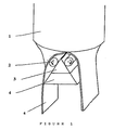
- Figure 1 is a diagram of a device of the invention for partitioning a plastic parison.
- the plastic parison is discharged as a tube from the die of the extrusion device (1).
- a body (3) optionally coolable, with a triangular cross section, arranged transversely to the direction of extrusion, functions as a cutting device or means of partitioning the plastic parison.
- the device also encompasses a heatable holder (4) on which the cutting device has been installed.
- Two pneumatically driven rolls (2) arranged in the immediate vicinity of the cutting device function as a means of drive of the invention.
- Installation in the immediate vicinity of the body (3) has the advantage that the two resultant parison sections (6) are distanced from the cutting device immediately after separation of the parison, and adhesion of the semifinished sheets to the device is therefore avoided.
- the tension exerted by the driven rolls (2) guides the plastic parison consistently over the cutting device, and the resultant semifinished sheets therefore have no, or comparatively very little, creasing or irregularity at the margins, i.e. at the cut edges.
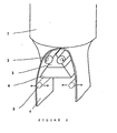
- Figure 2 is a diagram of another device of the invention for partitioning a plastic parison.
- the device shown in figure 2 differs from the device of figure 1 merely in the presence of two guide rollers (5) additionally installed. These guide rollers eliminate undesirable contact between the semifinished products (6) after the separation procedure and also provide the desired free space for components and devices to be introduced.
- the guide rollers (5) can be moved transversely to the direction of extrusion. The moveability of the guide rollers transversely to the direction of extrusion permits controlled setting of the distance between the semifinished products obtained.
- the driven rolls (2) in the device of figure 2 have been set into or integrated into the cutting device (3).
- Figure 3 depicts the distortion of the parison when devices not according to the invention are used (without a means of drive). The outcome is considerable deformation of the resultant cut edges, and also of the semifinished products themselves.
- Figure 4 depicts the device of the invention and the resultant partitioned parisons or resultant semifinished sheets. These have no creasing or irregularity, in particular at the margins, i.e. at the cut edges.
- the polymer processed was the same as that in figure 3.
Landscapes
- Engineering & Computer Science (AREA)
- Mechanical Engineering (AREA)
- Manufacturing & Machinery (AREA)
- Physics & Mathematics (AREA)
- Geometry (AREA)
- Blow-Moulding Or Thermoforming Of Plastics Or The Like (AREA)
- Extrusion Moulding Of Plastics Or The Like (AREA)
Abstract
Description
- The present invention relates to a device for partitioning a plastic parison to give one or more molten semifinished sheets.
- DE 100 42 121 discloses a process for producing hollow plastic articles and encompassing the following steps:
- a) production of a tubular plastic parison on a blow molding or coextrusion blow molding plant
- b) cutting the extruded or coextruded plastic parison open to give at least one semifinished open-surface product
- c) thermoforming of the resultant semifinished open-surface products to give half shells
- d) welding of the thermoformed half shells to give a hollow article
- The principle of this process for producing hollow plastic articles is that a plastic parison produced on a blow molding or coextrusion blow molding plant is cut open in an axial direction and the resultant molten semifinished sheets are placed in two thermoforming molds and formed to give the desired shape. This gives two half shells which can then be welded together at suitable temperatures, for example the temperature used for thermoforming. Production of the semifinished open-surface products on a blow molding plant provides reproducible wall thickness control and thus high design freedom.
- If a coextrusion blow molding plant is used, layers made from barrier polymers may be integrated into the semifinished product. If the semifinished product is single layer manufactured on a blow molding plant, barrier layers may be applied subsequently, for example by fluorination or painting. These coatings are preferably applied after the half shells have been welded together. However, the coating procedures may also take place prior to the welding process, where appropriate prior to or after the attachment of incorporated parts to the half shells.
- According to DE 100 42 121, the cutting of the plastic parison may take place prior to or after separation from the die of the extrusion head. It is also foreseen that the cutting of the plastic parison may actually take place during the extrusion process.
- The abovementioned process separates the usually approximately cylindrical parison (tube) at one or more locations longitudinally, using the pressure or push effect of the upstream melt to move the parison over a cutting device, such as one or more knives. Another factor promoting this procedure in cases where the arrangement of the extrusion device is vertical is the gravitational force exerted by the discharged melt.
- Japan patent publication JP 06 218792 discloses a device for partitioning a plastic parison that comprises a draw-off means for pulling the parison over the means of partitioning.
- Serious disadvantages have been found to be associated with the use of the cutting devices conventionally used for separating webs of plastic, for example conventional steel blades. In particular, it has been found that adhesion of the molten plastic to the device or blade often occurs. This adhesion causes undesirable deformation of the parison and of the molten semifinished sheets obtained after the separation procedure. It has also been found that in many instances, in particular at the start of the extrusion procedure, the pressure exerted by the upstream melt is not sufficient for the desired cutting procedure to be carried out consistently. The resistance exerted by the cutting device or the knife on the parison is frequently so great that severe distortion of the parison occurs, in particular at the start of the extrusion process, i.e. at the start of tube discharge from the die. The resultant cut edges, and the semifinished products themselves, are often considerably deformed as a result (figure 3).
- The problems described above are particularly relevant to parisons with especially high wall thickness. These problems can also be caused by some polymer materials when they are used in parisons. If a parison with relatively high wall thickness is passed over a conventional cutting device, marked distortion and creasing occurs, in particular at the resultant cut edges.
- It is an object of the present invention, therefore, to provide an apparatus which partitions plastic parisons, which does not have the abovementioned disadvantages of the prior art, and which can process parisons with thin-and-thick layer walls, made from high-to (inclusive) low-molecular-weight and/or high-to (inclusive) low-density materials. The device of the invention can therefore process a wider spectrum of polymers, and the nature of the extrusion products may be varied more widely. Further objects are apparent from the description of the invention hereinafter.
- We have found that this object is achieved by the features of
claim 1. - Advantageous embodiments of the device of the invention are defined in the subclaims.
- The invention provides a device for partitioning a plastic parison to give at least one semifinished open-surface product, where the device encompasses at least one means of partitioning the plastic parison and encompasses at least one means of drive or one draw-off mechanism.
- It has been found that the abovementioned problems can be overcome by equipping a device for partitioning a plastic parison with a drive system which draws off or transports the parison and/or the resultant molten semifinished sheet products. The effect of the draw-off mechanism is that the parison and, respectively, the semifinished products are pulled over the means of partitioning the plastic parison, this means being termed hereinafter a cutting device, thus compensating the resistance described above exerted by the cutting device on the parison, or the forces arising.
- The parisons partitioned by the device of the invention, or the resultant semifinished sheets, have no, or comparatively low levels of, creasing or irregularity, in particular at the margins, i.e. at the cut edges (figure 4).
- One particularly preferred drive system encompasses roller-type driven units, such as pneumatic floating rollers. However, driven devices of the invention also include driven belts, for example, or other suitable driven units. The driven units exert tension on the parison and, respectively, the semifinished products. This tension acts together with the compression brought about by the extrusion process to guide the parison in the desired manner consistently over the cutting device.
- It is also preferable that the driven units are smooth, profiled, or grooved, or have a suitable coating, in order to ensure sufficient friction and, respectively, continuous transport of the thermoplastic composition.
- According to the invention, it is particularly preferable to use two pneumatically driven rolls as a means of drive. The use of driven rollers or driven rolls, preferably installed in the direct vicinity of the cutting device, has the additional advantage that the parison section is distanced immediately from the cutting device after separation of the parison, thus avoiding adhesion of the semifinished sheets to the device.
- In one particularly preferred embodiment, the driven rolls are integrated within the cutting device. An example of a method for achieving this sets the means of drive, preferably the driven roll(s), into recesses on the means of partitioning the plastic parison.
- According to the invention, the driven rolls may also be installed separately, i.e. outside the cutting device.
- The device for partitioning the annular tube to give one or more molten semifinished sheets may in principle encompass almost any desired cutting devices and, respectively, knife designs and knife geometries. For example, the cutting device may encompass sharp-edged cutting units which may also, where appropriate, be exchangeable. Besides sharp-edged devices, use may also be made of edgeless, rectangular, or bar-shaped devices functioning as a knife or separator. However, a means of partitioning the plastic parison which encompasses a body of triangular cross section which has been arranged transversely to the direction of extrusion has proven particularly advantageous.
- It has proven advantageous for the cutting device used, which preferably encompasses a body made from metal or plastic, preferably with triangular cross section, to be provided with a coating which inhibits adhesion of the hot molten plastic. Suitable coatings encompass polytetrafluoroethylene, for example.
- The nature of the surface of the cutting device may be smooth or else grooved.
- In another preferred embodiment of the present invention, the device of the invention encompasses a holder for the means of partitioning the plastic parison and/or for the means of drive. The design of this holder is preferably such that it functions as a spacer for the semifinished open-surface products, so ensuring that undesirable contact between the semifinished products after the separation procedure is avoided, and free space is created for components and devices to be introduced.
- In another particularly preferred embodiment, the device of the invention is equipped with means of guiding the semifinished open-surface products. The means of guiding particularly preferably encompasses at least two guide rollers, which may, where appropriate, be driven, and can preferably be moved transversely to the direction of extrusion. The moveability of the guide rollers transversely to the direction of extrusion permits controlled setting of the distance between the semifinished products obtained.
- The abovementioned means of guiding or guide rollers may be used not only to control the distance between the semifinished products obtained but also to preform, and in particular flatten, the semifinished products. The device of the invention illustrated in figure 2 has guide rollers as well as the abovementioned driven rollers.
- Another embodiment of the invention provides, if required, for the holder or the means of guiding to be fully or else partially heatable, or coolable, or capable of being heated or cooled as desired. If advantageous, it is also possible for certain regions to be heated while at the same time other regions are cooled.
- The relative velocity of parison and, respectively, parison section to the means of drive here may vary.
- The invention further provides the use of the device of the invention for partitioning an extruded or coextruded plastic parison to give at least one semifinished open-surface product.
- Figure 1 is a diagram of a device of the invention for partitioning a plastic parison. The plastic parison is discharged as a tube from the die of the extrusion device (1). A body (3), optionally coolable, with a triangular cross section, arranged transversely to the direction of extrusion, functions as a cutting device or means of partitioning the plastic parison. The device also encompasses a heatable holder (4) on which the cutting device has been installed. Two pneumatically driven rolls (2) arranged in the immediate vicinity of the cutting device function as a means of drive of the invention. Installation in the immediate vicinity of the body (3) has the advantage that the two resultant parison sections (6) are distanced from the cutting device immediately after separation of the parison, and adhesion of the semifinished sheets to the device is therefore avoided. The tension exerted by the driven rolls (2) guides the plastic parison consistently over the cutting device, and the resultant semifinished sheets therefore have no, or comparatively very little, creasing or irregularity at the margins, i.e. at the cut edges.
- Figure 2 is a diagram of another device of the invention for partitioning a plastic parison. The device shown in figure 2 differs from the device of figure 1 merely in the presence of two guide rollers (5) additionally installed. These guide rollers eliminate undesirable contact between the semifinished products (6) after the separation procedure and also provide the desired free space for components and devices to be introduced. The guide rollers (5) can be moved transversely to the direction of extrusion. The moveability of the guide rollers transversely to the direction of extrusion permits controlled setting of the distance between the semifinished products obtained. The driven rolls (2) in the device of figure 2 have been set into or integrated into the cutting device (3).
- Figure 3 depicts the distortion of the parison when devices not according to the invention are used (without a means of drive). The outcome is considerable deformation of the resultant cut edges, and also of the semifinished products themselves.
- Figure 4 depicts the device of the invention and the resultant partitioned parisons or resultant semifinished sheets. These have no creasing or irregularity, in particular at the margins, i.e. at the cut edges. The polymer processed was the same as that in figure 3.
Claims (12)
- A device for partitioning a plastic parison to give at least one planar-surface part (6), using at least one means of partitioning the plastic parison (3), wherein the device encompasses at least one draw-off means (2), pulling the partitioned plastic parison over the means of partitioning thus compensating the resistance by the means of partitioning, characterized in that the means of partitioning the plastic parison and/or the draw-off means (2) are/is heatable or is coolable.
- A device as claimed in claim 1, wherein the means of drive has a smooth, profiled, grooved, and/or coated surface.
- A device as claimed in claim 1 or 2, wherein the means of drive encompasses at least one, preferably at least two driven rolls.
- A device as claimed in claim 3, wherein the at least one driven roll is installed in the direct vicinity of the cutting device distancing the partitioned plastic parison immediately from the cutting device after separation of the parison.
- A device as claimed in claim 1, 2, 3 or 4, wherein the means of partitioning the plastic parison has sharp-edged, where appropriate exchangeable, cutting units and/or edgeless, preferably bar-shaped units.
- A device as claimed in any of the preceding claims, wherein the means of partitioning the plastic parison comprises a body of triangular cross section which has been arranged transversely to the direction of extrusion.
- A device as claimed in claim 5 or 6, wherein the body or the unit is metallic and preferably has a coating of plastic.
- A device as claimed in any of the preceding claims, wherein the device has a holder for the means of partitioning the plastic parison and/or for the means of drive.
- A device as claimed in claim 8, wherein the design of the holder is such that it functions as spacer for the planar-surface parts.
- A device as claimed in any of the preceding claims, wherein the means of drive, preferably the driven roll(s), has been set into recesses on the means of partitioning the plastic parison.
- A device as claimed in any of the preceding claims, wherein the device has a means of guiding the planar-surface parts.
- A device as claimed in claim 11, wherein the means of guiding encompasses guide rollers which may, where appropriate, be driven, and can preferably be moved transversely to the direction of extrusion.
Applications Claiming Priority (5)
| Application Number | Priority Date | Filing Date | Title |
|---|---|---|---|
| DE10231867 | 2002-07-12 | ||
| DE2002131867 DE10231867A1 (en) | 2002-07-12 | 2002-07-12 | Plastic parison partitioning device for producing hollow plastic article, has two driven rolls arranged in vicinity of cutter placed on holder in extrusion direction |
| US40544502P | 2002-08-20 | 2002-08-20 | |
| US405445P | 2002-08-20 | ||
| PCT/EP2003/007363 WO2004007183A1 (en) | 2002-07-12 | 2003-07-09 | Giuding of a cut-open parison |
Publications (2)
| Publication Number | Publication Date |
|---|---|
| EP1521671A1 EP1521671A1 (en) | 2005-04-13 |
| EP1521671B1 true EP1521671B1 (en) | 2007-01-10 |
Family
ID=30116638
Family Applications (1)
| Application Number | Title | Priority Date | Filing Date |
|---|---|---|---|
| EP03763757A Expired - Lifetime EP1521671B1 (en) | 2002-07-12 | 2003-07-09 | Guiding of a cut-open parison |
Country Status (8)
| Country | Link |
|---|---|
| US (1) | US7556489B2 (en) |
| EP (1) | EP1521671B1 (en) |
| JP (1) | JP4295213B2 (en) |
| KR (1) | KR100919962B1 (en) |
| CN (1) | CN100548639C (en) |
| AU (1) | AU2003249997A1 (en) |
| DE (2) | DE10231867A1 (en) |
| WO (1) | WO2004007183A1 (en) |
Families Citing this family (11)
| Publication number | Priority date | Publication date | Assignee | Title |
|---|---|---|---|---|
| US20060141184A1 (en) * | 2002-07-12 | 2006-06-29 | Basell Polyolefine Gmbh | Multistage process for producing hollow plastic articles from half shells |
| JP5378802B2 (en) | 2006-02-03 | 2013-12-25 | イナジー・オートモーティブ・システムズ・リサーチ・(ソシエテ・アノニム) | Method and apparatus for manufacturing a fuel tank with internal accessories |
| JP5600640B2 (en) | 2011-05-19 | 2014-10-01 | 八千代工業株式会社 | Parison guide device |
| JP2012240362A (en) * | 2011-05-23 | 2012-12-10 | Japan Steel Works Ltd:The | Crosshead |
| JP5427834B2 (en) | 2011-05-23 | 2014-02-26 | 株式会社日本製鋼所 | Crosshead |
| JP2015101000A (en) | 2013-11-25 | 2015-06-04 | トヨタ自動車株式会社 | Resin sheet manufacturing apparatus, resin sheet manufacturing method, and fuel tank manufacturing method |
| JP6582638B2 (en) * | 2015-07-06 | 2019-10-02 | キョーラク株式会社 | Resin molding apparatus and resin molding method |
| JP6296021B2 (en) | 2015-08-24 | 2018-03-20 | トヨタ自動車株式会社 | Extrusion equipment |
| CN108136654B (en) | 2015-10-23 | 2020-10-30 | 八千代工业株式会社 | Parison Guidance |
| JP6501366B2 (en) | 2016-12-08 | 2019-04-17 | 株式会社Fts | Parison transfer device |
| JP6830373B2 (en) | 2017-02-17 | 2021-02-17 | 株式会社日本製鋼所 | Parison separation device, hollow molding machine and manufacturing method of hollow molded products |
Family Cites Families (23)
| Publication number | Priority date | Publication date | Assignee | Title |
|---|---|---|---|---|
| US24171A (en) * | 1859-05-24 | Improvement in cultivators | ||
| CA993165A (en) | 1971-11-22 | 1976-07-20 | Peter T. Schurman | Plastic article and blow molding method and apparatus |
| US4028034A (en) * | 1973-01-24 | 1977-06-07 | Cosden Oil & Chemical Company | Method and apparatus for blow molding plastic |
| US4022559A (en) * | 1975-10-06 | 1977-05-10 | Flexible Plastics Corporation | Parison slicer for plastic molding machines |
| FR2420415A1 (en) | 1978-03-22 | 1979-10-19 | Frame Sa | MANUFACTURING PROCESS BY EXTRUSION OF PARTS IN THERMOPLASTIC MATERIAL |
| US4550008A (en) * | 1981-06-15 | 1985-10-29 | Excell Corporation | Method for molding plastic products |
| US4626574A (en) * | 1982-07-21 | 1986-12-02 | Clopay Corporation | Linear low density polyethylene film and method of making |
| JPS61261021A (en) * | 1985-05-15 | 1986-11-19 | Kyoraku Co Ltd | Extruding exquipment for sheetlike molding article |
| DE3721459A1 (en) * | 1987-06-30 | 1989-01-12 | Focke & Co | METHOD AND DEVICE FOR FEEDING PACKAGING CUTTINGS TO A FOLDING UNIT |
| US5047196A (en) * | 1989-06-29 | 1991-09-10 | Tek-Rap, Inc. | Method for forming co-extruded adhesive tapes |
| JPH06218792A (en) * | 1993-01-21 | 1994-08-09 | Japan Steel Works Ltd:The | Manufacture and device of plastic sheet |
| GB9323267D0 (en) * | 1993-11-11 | 1994-01-05 | Hans Schochert | Transportation device for melted plastics |
| DE19814314B4 (en) | 1998-03-31 | 2016-07-28 | Volkswagen Ag | Process for the production of hollow bodies made of thermoplastic material and hollow body produced by this process |
| US6749418B2 (en) * | 1998-08-20 | 2004-06-15 | Scott A. W. Muirhead | Triple sheet thermoforming apparatus |
| US6294114B1 (en) * | 1998-08-20 | 2001-09-25 | Scott A. W. Muirhead | Triple sheet thermoforming apparatus, methods and articles |
| JP4270624B2 (en) | 1999-01-29 | 2009-06-03 | キョーラク株式会社 | Blow molding method for resin hollow molding products |
| BE1013191A3 (en) * | 1999-12-22 | 2001-10-02 | Solvay | Method for producing hollow plastic material. |
| US6661339B2 (en) * | 2000-01-24 | 2003-12-09 | Nextreme, L.L.C. | High performance fuel tank |
| DE10010900A1 (en) | 2000-03-07 | 2001-09-13 | Ludwig Kreth | Extrusion-pressing of high-impact, fuel tank blow-moldings, employs controlled blowing nozzle, core and separation strategy, followed by flange welding of shells formed |
| DE10042121A1 (en) * | 2000-08-28 | 2002-03-14 | Basell Polyolefine Gmbh | Process for the production of hollow plastic bodies |
| US20020105115A1 (en) * | 2001-02-08 | 2002-08-08 | Changize Sadr | Multiple part molding process |
| US20030090024A1 (en) * | 2001-11-14 | 2003-05-15 | Rubbermaid Incorporated | Method and apparatus for separating molded articles |
| US20060141184A1 (en) * | 2002-07-12 | 2006-06-29 | Basell Polyolefine Gmbh | Multistage process for producing hollow plastic articles from half shells |
-
2002
- 2002-07-12 DE DE2002131867 patent/DE10231867A1/en not_active Withdrawn
-
2003
- 2003-07-09 WO PCT/EP2003/007363 patent/WO2004007183A1/en not_active Ceased
- 2003-07-09 JP JP2004520535A patent/JP4295213B2/en not_active Expired - Fee Related
- 2003-07-09 KR KR1020057000335A patent/KR100919962B1/en not_active Expired - Fee Related
- 2003-07-09 EP EP03763757A patent/EP1521671B1/en not_active Expired - Lifetime
- 2003-07-09 US US10/520,537 patent/US7556489B2/en not_active Expired - Fee Related
- 2003-07-09 AU AU2003249997A patent/AU2003249997A1/en not_active Abandoned
- 2003-07-09 DE DE60311102T patent/DE60311102T2/en not_active Expired - Lifetime
- 2003-07-09 CN CNB038166194A patent/CN100548639C/en not_active Expired - Fee Related
Also Published As
| Publication number | Publication date |
|---|---|
| US20060099290A1 (en) | 2006-05-11 |
| JP2005532200A (en) | 2005-10-27 |
| US7556489B2 (en) | 2009-07-07 |
| DE60311102T2 (en) | 2007-06-21 |
| EP1521671A1 (en) | 2005-04-13 |
| CN100548639C (en) | 2009-10-14 |
| JP4295213B2 (en) | 2009-07-15 |
| AU2003249997A1 (en) | 2004-02-02 |
| DE10231867A1 (en) | 2004-01-22 |
| KR100919962B1 (en) | 2009-10-01 |
| KR20050018967A (en) | 2005-02-28 |
| WO2004007183A1 (en) | 2004-01-22 |
| DE60311102D1 (en) | 2007-02-22 |
| CN1668451A (en) | 2005-09-14 |
Similar Documents
| Publication | Publication Date | Title |
|---|---|---|
| EP1534496B1 (en) | Multistage process for producing hollow plastic articles from half shells | |
| US7556489B2 (en) | Guiding of a cut-open parison | |
| US4874657A (en) | Methods of producing biaxially-oriented polymer product, and the product produced thereby | |
| KR100958558B1 (en) | Multi-Step Method for Making Hollow Plastic Articles from Half Shells | |
| US5783229A (en) | Thermoforming process and apparatus | |
| EP0283284B1 (en) | Forming thermoplastic web materials | |
| US4722820A (en) | Molten theromplastic web feeding process | |
| JP2615162B2 (en) | Plasticized butyral sheet molding method | |
| KR20130063494A (en) | Method for the production of thermoplastic hollow articles | |
| CZ110099A3 (en) | Method and apparatus for biaxial drawing of plastic tubes | |
| WO1985002142A1 (en) | Molten thermoplastic web feeding process and apparatus | |
| EP0368302B1 (en) | Process and apparatus for the production of foamed polyolefin sheets | |
| US4411849A (en) | Method for forming a plurality of objects from a plurality of superimposed sheets | |
| US4301111A (en) | Horizontal blow molding | |
| US20250162229A1 (en) | Method for producing a vehicle interior component | |
| EP4678374A1 (en) | Extrusion film-forming apparatus | |
| Kim et al. | Cast Film Extrusion of Polyethylene | |
| DK202370026A1 (en) | Method for producing a vehicle interior component | |
| JP2024141099A (en) | Manufacturing method of extrusion molded products | |
| EP3106299B1 (en) | Multilayer film for manufacturing containers, producing method thereof and container comprising the film | |
| Cp | Second-stage I I'C omp ressio [''Feed F~ s~-Stange'>< Compress, on>< Feed |
Legal Events
| Date | Code | Title | Description |
|---|---|---|---|
| PUAI | Public reference made under article 153(3) epc to a published international application that has entered the european phase |
Free format text: ORIGINAL CODE: 0009012 |
|
| 17P | Request for examination filed |
Effective date: 20041030 |
|
| AK | Designated contracting states |
Kind code of ref document: A1 Designated state(s): AT BE BG CH CY CZ DE DK EE ES FI FR GB GR HU IE IT LI LU MC NL PT RO SE SI SK TR |
|
| AX | Request for extension of the european patent |
Extension state: AL LT LV MK |
|
| RAP1 | Party data changed (applicant data changed or rights of an application transferred) |
Owner name: BASELL POLYOLEFINE GMBH |
|
| DAX | Request for extension of the european patent (deleted) | ||
| GRAP | Despatch of communication of intention to grant a patent |
Free format text: ORIGINAL CODE: EPIDOSNIGR1 |
|
| RTI1 | Title (correction) |
Free format text: GUIDING OF A CUT-OPEN PARISON |
|
| GRAS | Grant fee paid |
Free format text: ORIGINAL CODE: EPIDOSNIGR3 |
|
| GRAA | (expected) grant |
Free format text: ORIGINAL CODE: 0009210 |
|
| AK | Designated contracting states |
Kind code of ref document: B1 Designated state(s): AT BE BG CH CY CZ DE DK EE ES FI FR GB GR HU IE IT LI LU MC NL PT RO SE SI SK TR |
|
| PG25 | Lapsed in a contracting state [announced via postgrant information from national office to epo] |
Ref country code: FI Free format text: LAPSE BECAUSE OF FAILURE TO SUBMIT A TRANSLATION OF THE DESCRIPTION OR TO PAY THE FEE WITHIN THE PRESCRIBED TIME-LIMIT Effective date: 20070110 Ref country code: CH Free format text: LAPSE BECAUSE OF FAILURE TO SUBMIT A TRANSLATION OF THE DESCRIPTION OR TO PAY THE FEE WITHIN THE PRESCRIBED TIME-LIMIT Effective date: 20070110 Ref country code: AT Free format text: LAPSE BECAUSE OF FAILURE TO SUBMIT A TRANSLATION OF THE DESCRIPTION OR TO PAY THE FEE WITHIN THE PRESCRIBED TIME-LIMIT Effective date: 20070110 Ref country code: DK Free format text: LAPSE BECAUSE OF FAILURE TO SUBMIT A TRANSLATION OF THE DESCRIPTION OR TO PAY THE FEE WITHIN THE PRESCRIBED TIME-LIMIT Effective date: 20070110 Ref country code: NL Free format text: LAPSE BECAUSE OF FAILURE TO SUBMIT A TRANSLATION OF THE DESCRIPTION OR TO PAY THE FEE WITHIN THE PRESCRIBED TIME-LIMIT Effective date: 20070110 Ref country code: SI Free format text: LAPSE BECAUSE OF FAILURE TO SUBMIT A TRANSLATION OF THE DESCRIPTION OR TO PAY THE FEE WITHIN THE PRESCRIBED TIME-LIMIT Effective date: 20070110 Ref country code: LI Free format text: LAPSE BECAUSE OF FAILURE TO SUBMIT A TRANSLATION OF THE DESCRIPTION OR TO PAY THE FEE WITHIN THE PRESCRIBED TIME-LIMIT Effective date: 20070110 |
|
| REG | Reference to a national code |
Ref country code: GB Ref legal event code: FG4D |
|
| REG | Reference to a national code |
Ref country code: IE Ref legal event code: FG4D |
|
| REF | Corresponds to: |
Ref document number: 60311102 Country of ref document: DE Date of ref document: 20070222 Kind code of ref document: P |
|
| PG25 | Lapsed in a contracting state [announced via postgrant information from national office to epo] |
Ref country code: SE Free format text: LAPSE BECAUSE OF FAILURE TO SUBMIT A TRANSLATION OF THE DESCRIPTION OR TO PAY THE FEE WITHIN THE PRESCRIBED TIME-LIMIT Effective date: 20070410 |
|
| PG25 | Lapsed in a contracting state [announced via postgrant information from national office to epo] |
Ref country code: BG Free format text: LAPSE BECAUSE OF EXPIRATION OF PROTECTION Effective date: 20070411 |
|
| PG25 | Lapsed in a contracting state [announced via postgrant information from national office to epo] |
Ref country code: ES Free format text: LAPSE BECAUSE OF FAILURE TO SUBMIT A TRANSLATION OF THE DESCRIPTION OR TO PAY THE FEE WITHIN THE PRESCRIBED TIME-LIMIT Effective date: 20070421 |
|
| PG25 | Lapsed in a contracting state [announced via postgrant information from national office to epo] |
Ref country code: PT Free format text: LAPSE BECAUSE OF FAILURE TO SUBMIT A TRANSLATION OF THE DESCRIPTION OR TO PAY THE FEE WITHIN THE PRESCRIBED TIME-LIMIT Effective date: 20070611 |
|
| NLV1 | Nl: lapsed or annulled due to failure to fulfill the requirements of art. 29p and 29m of the patents act | ||
| REG | Reference to a national code |
Ref country code: CH Ref legal event code: PL |
|
| ET | Fr: translation filed | ||
| PLBE | No opposition filed within time limit |
Free format text: ORIGINAL CODE: 0009261 |
|
| STAA | Information on the status of an ep patent application or granted ep patent |
Free format text: STATUS: NO OPPOSITION FILED WITHIN TIME LIMIT |
|
| PG25 | Lapsed in a contracting state [announced via postgrant information from national office to epo] |
Ref country code: SK Free format text: LAPSE BECAUSE OF FAILURE TO SUBMIT A TRANSLATION OF THE DESCRIPTION OR TO PAY THE FEE WITHIN THE PRESCRIBED TIME-LIMIT Effective date: 20070110 |
|
| 26N | No opposition filed |
Effective date: 20071011 |
|
| PG25 | Lapsed in a contracting state [announced via postgrant information from national office to epo] |
Ref country code: CZ Free format text: LAPSE BECAUSE OF FAILURE TO SUBMIT A TRANSLATION OF THE DESCRIPTION OR TO PAY THE FEE WITHIN THE PRESCRIBED TIME-LIMIT Effective date: 20070110 Ref country code: RO Free format text: LAPSE BECAUSE OF FAILURE TO SUBMIT A TRANSLATION OF THE DESCRIPTION OR TO PAY THE FEE WITHIN THE PRESCRIBED TIME-LIMIT Effective date: 20070110 |
|
| GBPC | Gb: european patent ceased through non-payment of renewal fee |
Effective date: 20070709 |
|
| PG25 | Lapsed in a contracting state [announced via postgrant information from national office to epo] |
Ref country code: MC Free format text: LAPSE BECAUSE OF NON-PAYMENT OF DUE FEES Effective date: 20070731 Ref country code: GR Free format text: LAPSE BECAUSE OF FAILURE TO SUBMIT A TRANSLATION OF THE DESCRIPTION OR TO PAY THE FEE WITHIN THE PRESCRIBED TIME-LIMIT Effective date: 20070411 |
|
| PG25 | Lapsed in a contracting state [announced via postgrant information from national office to epo] |
Ref country code: GB Free format text: LAPSE BECAUSE OF NON-PAYMENT OF DUE FEES Effective date: 20070709 |
|
| PG25 | Lapsed in a contracting state [announced via postgrant information from national office to epo] |
Ref country code: IE Free format text: LAPSE BECAUSE OF NON-PAYMENT OF DUE FEES Effective date: 20070709 |
|
| PG25 | Lapsed in a contracting state [announced via postgrant information from national office to epo] |
Ref country code: EE Free format text: LAPSE BECAUSE OF FAILURE TO SUBMIT A TRANSLATION OF THE DESCRIPTION OR TO PAY THE FEE WITHIN THE PRESCRIBED TIME-LIMIT Effective date: 20070110 |
|
| PG25 | Lapsed in a contracting state [announced via postgrant information from national office to epo] |
Ref country code: CY Free format text: LAPSE BECAUSE OF FAILURE TO SUBMIT A TRANSLATION OF THE DESCRIPTION OR TO PAY THE FEE WITHIN THE PRESCRIBED TIME-LIMIT Effective date: 20070110 |
|
| PG25 | Lapsed in a contracting state [announced via postgrant information from national office to epo] |
Ref country code: LU Free format text: LAPSE BECAUSE OF NON-PAYMENT OF DUE FEES Effective date: 20070709 |
|
| PG25 | Lapsed in a contracting state [announced via postgrant information from national office to epo] |
Ref country code: TR Free format text: LAPSE BECAUSE OF FAILURE TO SUBMIT A TRANSLATION OF THE DESCRIPTION OR TO PAY THE FEE WITHIN THE PRESCRIBED TIME-LIMIT Effective date: 20070110 Ref country code: HU Free format text: LAPSE BECAUSE OF FAILURE TO SUBMIT A TRANSLATION OF THE DESCRIPTION OR TO PAY THE FEE WITHIN THE PRESCRIBED TIME-LIMIT Effective date: 20070711 |
|
| PGFP | Annual fee paid to national office [announced via postgrant information from national office to epo] |
Ref country code: IT Payment date: 20090727 Year of fee payment: 7 |
|
| PG25 | Lapsed in a contracting state [announced via postgrant information from national office to epo] |
Ref country code: IT Free format text: LAPSE BECAUSE OF NON-PAYMENT OF DUE FEES Effective date: 20100709 |
|
| PGFP | Annual fee paid to national office [announced via postgrant information from national office to epo] |
Ref country code: FR Payment date: 20110805 Year of fee payment: 9 |
|
| PGFP | Annual fee paid to national office [announced via postgrant information from national office to epo] |
Ref country code: DE Payment date: 20110727 Year of fee payment: 9 |
|
| PGFP | Annual fee paid to national office [announced via postgrant information from national office to epo] |
Ref country code: BE Payment date: 20110728 Year of fee payment: 9 |
|
| BERE | Be: lapsed |
Owner name: BASELL POLYOLEFINE G.M.B.H. Effective date: 20120731 |
|
| REG | Reference to a national code |
Ref country code: FR Ref legal event code: ST Effective date: 20130329 |
|
| PG25 | Lapsed in a contracting state [announced via postgrant information from national office to epo] |
Ref country code: FR Free format text: LAPSE BECAUSE OF NON-PAYMENT OF DUE FEES Effective date: 20120731 Ref country code: DE Free format text: LAPSE BECAUSE OF NON-PAYMENT OF DUE FEES Effective date: 20130201 |
|
| PG25 | Lapsed in a contracting state [announced via postgrant information from national office to epo] |
Ref country code: BE Free format text: LAPSE BECAUSE OF NON-PAYMENT OF DUE FEES Effective date: 20120731 |
|
| REG | Reference to a national code |
Ref country code: DE Ref legal event code: R119 Ref document number: 60311102 Country of ref document: DE Effective date: 20130201 |