EP1521348A2 - Electrical machine - Google Patents
Electrical machine Download PDFInfo
- Publication number
- EP1521348A2 EP1521348A2 EP04255351A EP04255351A EP1521348A2 EP 1521348 A2 EP1521348 A2 EP 1521348A2 EP 04255351 A EP04255351 A EP 04255351A EP 04255351 A EP04255351 A EP 04255351A EP 1521348 A2 EP1521348 A2 EP 1521348A2
- Authority
- EP
- European Patent Office
- Prior art keywords
- clamp
- ring
- rotor
- assembly
- rings
- Prior art date
- Legal status (The legal status is an assumption and is not a legal conclusion. Google has not performed a legal analysis and makes no representation as to the accuracy of the status listed.)
- Granted
Links
Images


Classifications
-
- H—ELECTRICITY
- H02—GENERATION; CONVERSION OR DISTRIBUTION OF ELECTRIC POWER
- H02K—DYNAMO-ELECTRIC MACHINES
- H02K17/00—Asynchronous induction motors; Asynchronous induction generators
- H02K17/02—Asynchronous induction motors
- H02K17/16—Asynchronous induction motors having rotors with internally short-circuited windings, e.g. cage rotors
- H02K17/168—Asynchronous induction motors having rotors with internally short-circuited windings, e.g. cage rotors having single-cage rotors
Definitions
- the present invention relates to an electrical machine and more particularly to the end ring assemblies for a high speed electrical induction generator.
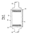
- Fig. 1 illustrates one conventional construction of a squirrel cage electrical induction machine.
- rotor bars 1 are located and fitted within slots 2 in a rotor core 3.
- These rotor bars 1 are usually rectangular or round drawn copper bars.
- the rotor bars 1 are connected to an end ring 4 that acts to short circuit the rotor bars 1 at each end of the rotor core 3.
- the rotor 3 is secured about a shaft 5, which in operation rotates.
- the end rings 4 are generally made from high strength copper alloy or copper chrome. Furthermore, in addition to using high strength copper alloy, these end rings 4 may be further reinforced by external banding in the form of carbon fibre over-wraps 6.
- an electrical machine comprising a laminated rotor core with rotor bars extending there through and end rings for structural integrity, each end ring comprising slots to receive the rotor bars and including a clamp section, the clamp section of the end ring is retained between an inner clamp ring and an outer clamp ring.
- an end ring assembly for an electrical machine, the assembly comprising an end ring with slots for rotor bars and a clamp section for retention by a clamp ring arrangement, the clamp ring arrangement comprising an inner clamp ring and an outer clamp ring which when in juxtaposed position form a clamp cavity to retain the clamp section of the end ring.
- the clamp section of the end ring may be enlarged and in the preferred embodiment of the present invention the clamp section and the cavity have a reciprocal dove tail shape.
- the rotor bars are hollow. Furthermore, these hollow rotor bars may be expanded within the slots for retention.
- the end ring is formed from copper or copper alloy.
- the clamping rings are formed from a ferritic steel.
- the rotor core is secured upon a shaft.
- the inner clamp ring encloses the rotor bars to minimise windage.
- the space between the inner clamp ring and the clamp bar is filled.
- the rotor slots are fully closed in order to further reduce rotor core windage upon rotation.
- the rotor bars may be electrically and mechanically joined to the end rings by brazing or solder or welding.
- those rotor bars are hydraulically expanded to improve retention of the rotor bars in the slots of the rotor core.
- the inner and outer clamp rings are secured together by appropriate means.
- appropriate means includes bolts.
- Figure 3 illustrates a rotor core assembly 30 in accordance with the present invention.
- a laminated rotor core 33 is secured upon a through shaft 35 with end ring assemblies.
- Rotor bars 31 extend through slots 32 in the core 33. At either end these rotor bars 31 are secured to end rings 34.
- the rotor bars 31 are hollow drawn copper bars whilst the end rings 34 are formed from a copper alloy.
- these end bars 34 include clamping sections 36 which have a dove-tail cross-section.
- the end rings 34 extend around the shaft 35 and as illustrated include slot ends to which ends of the rotor bars 31 are secured.
- clamp sections 36 in the form of dove tail sections are clamped between respective inner clamp rings 37 and outer clamp rings 38.
- These clamp rings 37, 38 include V sections which when there is juxtaposed association between the rings 37, 38 form a cavity in order to retain the clamp section 36 of the end rings 34.
- the inner clamp ring 37 is secured upon the shaft 34 through a shrink fit interference process in order to provide axial location and effective clamping of the ring 37 on the shaft and therefore, the core 33 about that shaft 35.
- the rotor bars 31 as indicated are located within slots 32 about the circumference of the core 33. Once located within the slots 32, the ends of the rotor bars 31 are joined to the end rings 34 by an appropriate method to ensure electrical continuity between those bars and the ring 34. Typically, they are joined by welding or brazing or soldering.
- the rotor core 33 is formed from steel laminations, which are punched in order to provide the fully closed rotor slots 32.
- the outer surface of the rotor core 33 is smooth which upon rotation provides lower windage resistance losses to such rotation.
- fully closed slots 32 increase the mechanical strength and integrity of the rotor core 33.
- the rotor bars 31 are typically hollow drawn copper bars. By appropriate hydraulic expansion, the bars 31 can gradually expand in order to further improve electrical and mechanical retention of the rotor bars 31 in the slots 32 of the core 33. Hydraulic expansion prevents thermal or mechanical movement between the bars 31 and the core 33, which through the operational cycles may cause fretting of the inter-engaging surfaces between those bars 31 and the slot 32 surfaces. Where hydraulic expansion is used it will be appreciated that round bars 31 and round slots 32 are preferable in comparison with other bar and slot cross-sections.
- the cross-sectional area of the end rings 34 will be chosen such that the end rings 34 have an electrical current density similar to that of the rotor bars 31 secured around the core 33.
- copper alloy is used with regard to formation of the end rings 34.
- this copper alloy is a copper chrome alloy with a yield stress in the order of 250 to 300 Newtons per square millimetre.
- Rotational stresses presented to the end rings 34 and clamping rings 37, 38 may be estimated by two-dimensional axisymmetric finite element analysis to determine the necessary properties of materials and how the components best structurally formed in order to be effective within an operational electrical machine.
- the range of growth of each end ring 34 will be determined in terms of thermal and centrifugal expansion but this radial growth will be dominated by the greater mechanical strength of the clamp rings 37, 38. In such circumstances, no significant differential growth occurs between the end rings 34 and the core 33 due to the anchoring effect of the clamp rings 37, 38.
- the properties of copper in the rotor bars 31 whether they be solid or hollow will allow a degree of flexibility.
- the rotor core assembly 30 depicted in Fig. 3 rotates at high speed in operation within an electrical machine.
- windage problems must be considered in an operational design.
- the exposed portion of the rotor bars 31 between the ends 39 of the core and end rings 34 will generally be shielded with a low density plastic filler.
- this filler may be a glass reinforced epoxy bandage.
- the purpose of shielding is to reduce rotor windage losses.
- the inner clamp ring 37 may be configured to extend radially to a flush circumferential perimeter surface with the rotor core 33. In order to achieve this flush relationship between the outer surface of the inner clamp ring 37 and the core 33, these rings 37 will include clearance holes to accommodate the rotor bars 31.
- the clamp rings 37, 38 are made from an alloy with high electrical resistivity. Such high electrical resistivity will minimise electrical eddy current losses in the end regions of the rotor core assembly 30.
- An example of such a high electrical resistivity material is a ferritic steel with a similar thermal expansion coefficient to the steel utilised in the rotor core 33 laminations.
- Such an approach minimises any potential problems of differential radial expansion between the core 33 and the clamp rings 37, 38. It will be understood that temperature differentials between the clamp rings 37, 38 and the core 33 are avoided by the relatively close proximity of those rings 37, 38 to the rotor core 33.
- the present invention provides a high speed rotor assembly for electrical induction generators in which there is adequate support for the end rings 34 whilst only using conventional materials such as copper chrome alloy for the end rings 34 and ferritic steels for the clamp rings 37, 38. In such circumstances, more expensive materials are not required to achieve desired operational performance. Furthermore, it is not necessary to reinforce the end ring assembly with additional features such as banding as shown in Fig. 1.
- the present rotor core assembly configuration can be accommodated within a conventional through shaft rotor design without significant modification. In such circumstances, it may be possible to upgrade existing induction generators with the present invention. It will also be understood that the present invention minimises problems with respect to differential radial growth between the core 33, and rings 34, and clamp rings 37, 38 such that the possibility for rotor bar 31 breakage is reduced.
- a first inner clamp ring 37 will be located at one end of a shaft 35.
- the first inner clamp ring 37 will typically be secured by an interference fit at the appropriate location on the shaft 35 such that there is robust axial location of that clamp ring 37 on the shaft 35. It will be appreciated that this first clamp ring 37 essentially establishes the rotor core 33 position on the shaft 35.
- the rotor core 33 is located upon the shaft 35 as the next step of assembly manufacture. Normally, there is a slight interference fit due to shrinkage association by the core 33 upon the shaft 35 through a central aperture of that core 33. Such slight interference location will ensure good radial location of the core 33 upon the shaft 35 when rotated at full speed in operation.
- the next step of manufacture involves securing a second inner clamp ring 37 at the other end of the core 33.
- the second inner clamp ring 37 is secured to the shaft 35 with an interference fit such that the core 33 is under axial compression.
- the rotor bars 35 are inserted through the slots 32 in the core 33. Where the inner clamp rings 37 extend to be flushed with the core 33 in order to reduce rotation windage problems, then the bars 31 also pass through the apertures in those clamp rings 37.
- the end rings 34 are located over the ends of those bars 31 at an appropriate position. This position is normally dictated by the dove-tail clamp ends 36 engaging a cavity recess part of the inner clamp ring 37. End rings 34 are located at both sides of the core 33 and typically a portion of each rotor bar extends beyond its slot in the end ring 34. Normally, the end rings 34 are temporary clamped to the inner clamp ring 37 to hold them in place whilst the rotor bars 31 are electrically connected to the end rings 34. This electrical connection is usually through a brazed or soldered or welded joint. Alternatively, there is an interference fit between the bars and the end rings. The interference fit could be achieved by hydraulically expanding the rotor bars or by swaging.
- a temporary hydraulic hose is secured to one or both ends of the bars 31 to enable hydraulic expansion of each bar 31 either in turn or collectively in order to achieve good location of the bars 31 within the slots 32 of the core 33. It will be understood in order to achieve this hydraulic expansion, the bars 31 must be hollow and one end plugged whilst the other is connected to hydraulic pressure or both ends may be presented with such hydraulic pressure through appropriate couplings.
- outer clamp rings 38 are now presented along the shaft 35 and secured in position.
- These outer clamp rings 38 include a reciprocal recess to clamp a dove tailed clamp section 36 of the end rings 34 in a cavity formed between the opposed recesses of the inner clamp rings 37 and the outer clamp rings 38.
- the outer clamp rings 38 are then secured to the inner clamp rings 31.
- the clamp rings 37 and 38 are secured by bolts, which extend therebetween but alternative arrangements may be used.
- Compliance is provided by the exposed parts of the bars 31 between the ends 39 of the core and the end rings 34.
- the length of the exposed parts of the bars 31 may be adjusted to provide increased compliance if necessary.
- a rotor core assembly 30 is formed which can then be used as part of a high-speed electrical induction generator with reduced problems with respect to thermal and centrifugal growth differentials between the various components of the assembly 30. Such reduced radial growth differentials will in turn reduce the potential for rotor bar 31 failure through breakage.
Landscapes
- Engineering & Computer Science (AREA)
- Power Engineering (AREA)
- Iron Core Of Rotating Electric Machines (AREA)
- Induction Machinery (AREA)
- Reciprocating, Oscillating Or Vibrating Motors (AREA)
- Devices For Conveying Motion By Means Of Endless Flexible Members (AREA)
- Glass Compositions (AREA)
- Eye Examination Apparatus (AREA)
Abstract
Description
Claims (20)
- An end ring assembly for an electrical machine, the assembly comprising an end ring (34) with slots for rotor bars (31) and a clamp section (36), characterised in that the clamp section (36) of the end ring (34) is retained between an inner clamp ring (37) and an outer clamp ring (38) which in juxtaposed position form a clamp cavity to retain the clamp section (36) of the end ring (34).
- An assembly as claimed in claim 1 characterised in that the clamp section (36) of the end ring (34) is enlarged.
- An assembly as claimed in claim 2 characterised in that the clamp section (36) and the clamp cavity have a reciprocal dove tail shape.
- An assembly as claimed in any of claims 1-3 characterised in that the rotor bars (31) are hollow.
- An assembly as claimed in claim 4 characterised in that the hollow rotor bars (31) are expanded within the slots for retention.
- An assembly as claimed in any preceding claim, characterised in that the end ring (34) is formed from copper or copper alloy.
- An assembly as claimed in any preceding claim, characterised in that the clamping rings (37,38) are formed from a ferritic steel.
- An assembly as claimed in any preceding claim, characterised in that the rotor core (33) is secured upon a shaft (35).
- An assembly as claimed in any preceding claim, characterised in that there is an interference fit between the rotor bars (31) and the end ring (34).
- An assembly as claimed in any preceding claim, characterised in that there is an interference fit between the clamp rings (37,38) and the shaft (35).
- An assembly as claimed in any preceding claim, characterised in that the inner clamp ring (37) encloses the rotor bars (31) to minimise windage.
- An assembly as claimed in any of claims 1 to 11, characterised in that the space between the inner clamp ring (37) and the rotor bars (31) is filled.
- An assembly as claimed in any preceding claim, characterised in that the slots (32) are fully closed in order to further reduce rotor core windage upon rotation.
- An electrical machine comprising a laminated rotor core (33) with rotor bars (31) extending there through and end rings (34) for structural integrity, each end ring (34) comprising slots to receive the rotor bars and includes a clamp section characterised in that the clamp section (36) is retained between an inner clamp ring (37) and an outer clamp ring (38).
- An electrical machine as claimed in claim 14, characterised in that each end ring assembly is as claimed in any of claims 1 to 13.
- A method of forming an electrical machine characterised in that it comprises the steps of :-a) securing a first inner clamp ring (37) towards one end of a shaft (35);b) locating a laminated core (33) upon that shaft (35) against the first secured inner clamp ring (37);c) securing a second inner clamp ring (37) to the other side of the rotor core (33) upon the shaft (35) whereby the core (33) is under axial compression along the shaft (35);d) locating rotor bars (31) in slots (32) of the rotor core (33);e) locating end rings (34) in abutment with the respective inner clamp ring (37), with the ends of the rotor bars (31) located in slots of each respective end ring (34);f) locating outer clamp rings (38) in a juxtaposed position with a respective end ring (34) with a clamp section (36) of each end ring (34) clamped between the respective inner clamp ring (37) and a respective outer clamp ring (38); and,g) electrically and mechanically joining the end rings (34) with the rotor bars (31).
- A method as claimed in claim 16 characterised in that the rotor bars (31) are electrical and mechanically joined to the end rings (34) by brazing or solder or welding.
- A method as claimed in claim 17 characterised in that hollow rotor bars (31) are used, the rotor bars (31) are hydraulically expanded to improve retention of the rotor bars (31) in the slots of the rotor core (33).
- A method as claimed in any of claims 16 to 18, characterised in that the inner (37) and outer (38) clamp rings are secured together by appropriate means.
- A method as claimed in claim 19 characterised in that appropriate means includes bolts.
Applications Claiming Priority (2)
| Application Number | Priority Date | Filing Date | Title |
|---|---|---|---|
| GB0323232 | 2003-10-03 | ||
| GBGB0323232.9A GB0323232D0 (en) | 2003-10-03 | 2003-10-03 | Electrical machine |
Publications (3)
| Publication Number | Publication Date |
|---|---|
| EP1521348A2 true EP1521348A2 (en) | 2005-04-06 |
| EP1521348A3 EP1521348A3 (en) | 2005-10-12 |
| EP1521348B1 EP1521348B1 (en) | 2008-09-03 |
Family
ID=29415491
Family Applications (1)
| Application Number | Title | Priority Date | Filing Date |
|---|---|---|---|
| EP04255351A Expired - Lifetime EP1521348B1 (en) | 2003-10-03 | 2004-09-03 | Electrical machine |
Country Status (6)
| Country | Link |
|---|---|
| US (1) | US7339303B2 (en) |
| EP (1) | EP1521348B1 (en) |
| AT (1) | ATE407470T1 (en) |
| DE (1) | DE602004016262D1 (en) |
| ES (1) | ES2312930T3 (en) |
| GB (1) | GB0323232D0 (en) |
Cited By (3)
| Publication number | Priority date | Publication date | Assignee | Title |
|---|---|---|---|---|
| CN108475970A (en) * | 2016-03-23 | 2018-08-31 | 宝马股份公司 | Rotor for asynchronous machine |
| EP3823142A1 (en) * | 2019-11-18 | 2021-05-19 | Siemens Aktiengesellschaft | Cage rotor with support element |
| RU2802343C1 (en) * | 2019-11-18 | 2023-08-25 | Сименс Акциенгезелльшафт | Short-closed rotor with support element |
Families Citing this family (12)
| Publication number | Priority date | Publication date | Assignee | Title |
|---|---|---|---|---|
| DE102004046440B4 (en) * | 2004-09-24 | 2018-05-24 | Siemens Aktiengesellschaft | Rotor with clamping device |
| TWI441658B (en) * | 2008-03-11 | 2014-06-21 | Takeda Pharmaceutical | Orally-disintegrating solid preparation |
| US20100171387A1 (en) * | 2009-01-07 | 2010-07-08 | Bae Systems Controls Inc. | Die Cast Rotor With Steel End Rings to Contain Aluminum |
| US8274190B2 (en) | 2010-05-28 | 2012-09-25 | General Electric Company | Electric machine rotor bar and method of making same |
| US8684257B2 (en) * | 2011-08-15 | 2014-04-01 | GM Global Technology Operations LLC | Rotor for electric motor and brazing process |
| US8458895B2 (en) | 2011-09-30 | 2013-06-11 | General Electric Company | Assembly for positioning a rotor retaining ring |
| EP2592729B1 (en) * | 2011-11-09 | 2018-05-02 | Siemens Aktiengesellschaft | Rotor of an asynchronous machine with holding element |
| US9496775B2 (en) * | 2013-06-19 | 2016-11-15 | Tesla Motors, Inc. | Controlling end ring balance in pre-balancing spinning process |
| KR101878677B1 (en) * | 2017-06-29 | 2018-07-16 | 엘지전자 주식회사 | Rotor for electric motor |
| JP6848029B1 (en) * | 2019-10-08 | 2021-03-24 | 株式会社東芝 | Rotor of rotating electric machine |
| JP2023026866A (en) * | 2021-08-16 | 2023-03-01 | 株式会社日立インダストリアルプロダクツ | Induction motor and railway vehicle |
| EP4401290A1 (en) * | 2023-01-10 | 2024-07-17 | Siemens Aktiengesellschaft | Method for producing a short-circuit rotor |
Family Cites Families (18)
| Publication number | Priority date | Publication date | Assignee | Title |
|---|---|---|---|---|
| GB231462A (en) * | 1924-03-25 | 1925-12-03 | Deutsche Werke Aktiengesellschaft | |
| GB267670A (en) * | 1926-02-03 | 1927-03-24 | English Electric Co Ltd | Improvements in asynchronous electric motors |
| GB704555A (en) | 1951-05-30 | 1954-02-24 | Vickers Electrical Co Ltd | Improvements relating to the construction of electric motors |
| GB1394063A (en) * | 1971-10-13 | 1975-05-14 | Laurence Scott Electromotors L | Rotors of squirrel cage motors |
| US3977068A (en) * | 1975-07-14 | 1976-08-31 | Balcke-Durr Aktiengesellschaft | Device and method for expansion-swaging tubes into the bores of a tube plate |
| DE2721211A1 (en) * | 1977-05-11 | 1978-11-16 | Siemens Ag | High speed async. motor squirrel-cage rotor - has centering ring for each short circuit ring, whose free inside portion has annular recess for short circuit ring abutment |
| JPS5869451A (en) * | 1981-10-21 | 1983-04-25 | Hitachi Ltd | Manufacturing method of squirrel cage rotor |
| US4802273A (en) * | 1985-07-18 | 1989-02-07 | Cockerill Mechanical Industries | Hydraulic expansion tool for tubular element |
| CA1289776C (en) * | 1986-07-12 | 1991-10-01 | Geoffrey Michael Suter | Camshaft and method for its production |
| JPH0716297B2 (en) * | 1987-11-27 | 1995-02-22 | 三菱電機株式会社 | Electric motor |
| EP0343313B1 (en) * | 1988-05-27 | 1994-09-28 | Gec Alsthom Acec Energie S.A. | Electric motor of high power and high rotation speed |
| JPH054772U (en) * | 1991-06-28 | 1993-01-22 | フアナツク株式会社 | High speed induction AC motor rotor assembly structure |
| JPH05115162A (en) | 1991-07-02 | 1993-05-07 | Ebara Corp | Squirrel-cage rotor and fabrication thereof |
| US6534891B2 (en) * | 1992-01-15 | 2003-03-18 | General Electric Company | High speed induction motor rotor and method of fabrication |
| JP2911315B2 (en) * | 1992-09-17 | 1999-06-23 | ファナック株式会社 | High-speed induction motor cage rotor |
| DE19521700A1 (en) * | 1995-06-14 | 1996-12-19 | Abb Daimler Benz Transp | Squirrel cage for an asynchronous machine |
| US6159305A (en) * | 1998-07-14 | 2000-12-12 | General Electric Company | High speed induction motor rotor and method of fabrication |
| DE10234368C1 (en) * | 2002-07-27 | 2003-09-25 | Daimler Chrysler Ag | Manufacturing method for shaft provided with function elements uses plastic expansion of hollow shaft by internal fluidic pressure and elastic expansion of function elements fitted to shaft |
-
2003
- 2003-10-03 GB GBGB0323232.9A patent/GB0323232D0/en not_active Ceased
-
2004
- 2004-09-03 DE DE602004016262T patent/DE602004016262D1/en not_active Expired - Lifetime
- 2004-09-03 ES ES04255351T patent/ES2312930T3/en not_active Expired - Lifetime
- 2004-09-03 AT AT04255351T patent/ATE407470T1/en not_active IP Right Cessation
- 2004-09-03 EP EP04255351A patent/EP1521348B1/en not_active Expired - Lifetime
- 2004-10-01 US US10/954,268 patent/US7339303B2/en not_active Expired - Lifetime
Cited By (6)
| Publication number | Priority date | Publication date | Assignee | Title |
|---|---|---|---|---|
| CN108475970A (en) * | 2016-03-23 | 2018-08-31 | 宝马股份公司 | Rotor for asynchronous machine |
| US10630152B2 (en) | 2016-03-23 | 2020-04-21 | Bayerische Motoren Werke Aktiengesellschaft | Rotor for an asynchronous machine |
| CN108475970B (en) * | 2016-03-23 | 2020-06-09 | 宝马股份公司 | Rotors for asynchronous motors |
| EP3823142A1 (en) * | 2019-11-18 | 2021-05-19 | Siemens Aktiengesellschaft | Cage rotor with support element |
| WO2021099118A1 (en) * | 2019-11-18 | 2021-05-27 | Siemens Aktiengesellschaft | Cage rotor with support element |
| RU2802343C1 (en) * | 2019-11-18 | 2023-08-25 | Сименс Акциенгезелльшафт | Short-closed rotor with support element |
Also Published As
| Publication number | Publication date |
|---|---|
| US20050073216A1 (en) | 2005-04-07 |
| ATE407470T1 (en) | 2008-09-15 |
| DE602004016262D1 (en) | 2008-10-16 |
| ES2312930T3 (en) | 2009-03-01 |
| GB0323232D0 (en) | 2003-11-05 |
| US7339303B2 (en) | 2008-03-04 |
| EP1521348B1 (en) | 2008-09-03 |
| EP1521348A3 (en) | 2005-10-12 |
Similar Documents
| Publication | Publication Date | Title |
|---|---|---|
| US7339303B2 (en) | Electrical machine | |
| US8181333B2 (en) | Method of manufacturing squirrel-cage rotor | |
| US6711805B2 (en) | Process for the production of a rotor, containing permanent magnets, of a synchronous machine, and rotor produced according to this process | |
| EP0013157B1 (en) | Permanent magnet rotors, especially for dynamo-electric machines | |
| CN102801259B (en) | Induction rotor assembly and method of manufacturing same | |
| EP0087478B1 (en) | Laminated stator core | |
| JP5080664B2 (en) | Induction motor cage rotor | |
| US20180269761A1 (en) | Cage Rotor and Method for the Production Thereof | |
| KR101881591B1 (en) | Dynamoelectric machine support system | |
| KR102789923B1 (en) | Rotor for permanent magnet synchronous machine and permanent magnet synchronous machine | |
| CA2215765C (en) | Rotors and methods of manufacturing such rotors | |
| CN110971098A (en) | Motor assembly for reducing leakage of rotor column | |
| US7546674B2 (en) | Method of rotor assembly without the hub | |
| JP7080278B2 (en) | Rotor, rotor manufacturing method and rotary electric machine | |
| US7839040B2 (en) | Permanent-magnet generator rotor for gas turbine, manufacturing method therefor, and gas turbine | |
| JP2000069719A (en) | Rotor of permanent magnet type rotating electric machine and method of manufacturing the same | |
| JP3480185B2 (en) | Rotor of squirrel-cage induction motor rotating at high speed and manufacturing method thereof | |
| EP2677639A1 (en) | Slip ring device and rotating electric machine using same | |
| JPH08503051A (en) | Compressor equipment | |
| EP4718693A1 (en) | Squirrel-cage rotor, method for manufacturing a squirrel cage rotor by casting, and set of casting forms useful for performing the method | |
| JP3727476B2 (en) | Rotating electric machine stator | |
| JP2000134831A (en) | Rotating electric machine stator | |
| CN212677055U (en) | Filled type rotor end ring welding structure of asynchronous motor | |
| CN215911955U (en) | Multi-section SMC iron core, stator and disc type motor | |
| JP2007043883A (en) | Stator core and method for manufacturing stator core |
Legal Events
| Date | Code | Title | Description |
|---|---|---|---|
| PUAI | Public reference made under article 153(3) epc to a published international application that has entered the european phase |
Free format text: ORIGINAL CODE: 0009012 |
|
| AK | Designated contracting states |
Kind code of ref document: A2 Designated state(s): AT BE BG CH CY CZ DE DK EE ES FI FR GB GR HU IE IT LI LU MC NL PL PT RO SE SI SK TR |
|
| AX | Request for extension of the european patent |
Extension state: AL HR LT LV MK |
|
| PUAL | Search report despatched |
Free format text: ORIGINAL CODE: 0009013 |
|
| AK | Designated contracting states |
Kind code of ref document: A3 Designated state(s): AT BE BG CH CY CZ DE DK EE ES FI FR GB GR HU IE IT LI LU MC NL PL PT RO SE SI SK TR |
|
| AX | Request for extension of the european patent |
Extension state: AL HR LT LV MK |
|
| 17P | Request for examination filed |
Effective date: 20051014 |
|
| AKX | Designation fees paid |
Designated state(s): AT BE BG CH CY CZ DE DK EE ES FI FR GB GR HU IE IT LI LU MC NL PL PT RO SE SI SK TR |
|
| GRAP | Despatch of communication of intention to grant a patent |
Free format text: ORIGINAL CODE: EPIDOSNIGR1 |
|
| GRAS | Grant fee paid |
Free format text: ORIGINAL CODE: EPIDOSNIGR3 |
|
| GRAA | (expected) grant |
Free format text: ORIGINAL CODE: 0009210 |
|
| AK | Designated contracting states |
Kind code of ref document: B1 Designated state(s): AT BE BG CH CY CZ DE DK EE ES FI FR GB GR HU IE IT LI LU MC NL PL PT RO SE SI SK TR |
|
| REG | Reference to a national code |
Ref country code: GB Ref legal event code: FG4D |
|
| REG | Reference to a national code |
Ref country code: CH Ref legal event code: EP Ref country code: CH Ref legal event code: NV Representative=s name: KIRKER & CIE S.A. |
|
| REG | Reference to a national code |
Ref country code: IE Ref legal event code: FG4D |
|
| REF | Corresponds to: |
Ref document number: 602004016262 Country of ref document: DE Date of ref document: 20081016 Kind code of ref document: P |
|
| REG | Reference to a national code |
Ref country code: SE Ref legal event code: TRGR |
|
| PG25 | Lapsed in a contracting state [announced via postgrant information from national office to epo] |
Ref country code: NL Free format text: LAPSE BECAUSE OF FAILURE TO SUBMIT A TRANSLATION OF THE DESCRIPTION OR TO PAY THE FEE WITHIN THE PRESCRIBED TIME-LIMIT Effective date: 20080903 |
|
| PG25 | Lapsed in a contracting state [announced via postgrant information from national office to epo] |
Ref country code: SI Free format text: LAPSE BECAUSE OF FAILURE TO SUBMIT A TRANSLATION OF THE DESCRIPTION OR TO PAY THE FEE WITHIN THE PRESCRIBED TIME-LIMIT Effective date: 20080903 Ref country code: AT Free format text: LAPSE BECAUSE OF FAILURE TO SUBMIT A TRANSLATION OF THE DESCRIPTION OR TO PAY THE FEE WITHIN THE PRESCRIBED TIME-LIMIT Effective date: 20080903 |
|
| REG | Reference to a national code |
Ref country code: ES Ref legal event code: FG2A Ref document number: 2312930 Country of ref document: ES Kind code of ref document: T3 |
|
| NLV1 | Nl: lapsed or annulled due to failure to fulfill the requirements of art. 29p and 29m of the patents act | ||
| PG25 | Lapsed in a contracting state [announced via postgrant information from national office to epo] |
Ref country code: BE Free format text: LAPSE BECAUSE OF FAILURE TO SUBMIT A TRANSLATION OF THE DESCRIPTION OR TO PAY THE FEE WITHIN THE PRESCRIBED TIME-LIMIT Effective date: 20080903 |
|
| PG25 | Lapsed in a contracting state [announced via postgrant information from national office to epo] |
Ref country code: BG Free format text: LAPSE BECAUSE OF FAILURE TO SUBMIT A TRANSLATION OF THE DESCRIPTION OR TO PAY THE FEE WITHIN THE PRESCRIBED TIME-LIMIT Effective date: 20081203 Ref country code: MC Free format text: LAPSE BECAUSE OF NON-PAYMENT OF DUE FEES Effective date: 20080930 |
|
| PG25 | Lapsed in a contracting state [announced via postgrant information from national office to epo] |
Ref country code: CZ Free format text: LAPSE BECAUSE OF FAILURE TO SUBMIT A TRANSLATION OF THE DESCRIPTION OR TO PAY THE FEE WITHIN THE PRESCRIBED TIME-LIMIT Effective date: 20080903 Ref country code: PT Free format text: LAPSE BECAUSE OF FAILURE TO SUBMIT A TRANSLATION OF THE DESCRIPTION OR TO PAY THE FEE WITHIN THE PRESCRIBED TIME-LIMIT Effective date: 20090203 Ref country code: SK Free format text: LAPSE BECAUSE OF FAILURE TO SUBMIT A TRANSLATION OF THE DESCRIPTION OR TO PAY THE FEE WITHIN THE PRESCRIBED TIME-LIMIT Effective date: 20080903 Ref country code: RO Free format text: LAPSE BECAUSE OF FAILURE TO SUBMIT A TRANSLATION OF THE DESCRIPTION OR TO PAY THE FEE WITHIN THE PRESCRIBED TIME-LIMIT Effective date: 20080903 |
|
| PLBE | No opposition filed within time limit |
Free format text: ORIGINAL CODE: 0009261 |
|
| STAA | Information on the status of an ep patent application or granted ep patent |
Free format text: STATUS: NO OPPOSITION FILED WITHIN TIME LIMIT |
|
| PG25 | Lapsed in a contracting state [announced via postgrant information from national office to epo] |
Ref country code: EE Free format text: LAPSE BECAUSE OF FAILURE TO SUBMIT A TRANSLATION OF THE DESCRIPTION OR TO PAY THE FEE WITHIN THE PRESCRIBED TIME-LIMIT Effective date: 20080903 Ref country code: DK Free format text: LAPSE BECAUSE OF FAILURE TO SUBMIT A TRANSLATION OF THE DESCRIPTION OR TO PAY THE FEE WITHIN THE PRESCRIBED TIME-LIMIT Effective date: 20080903 Ref country code: IE Free format text: LAPSE BECAUSE OF NON-PAYMENT OF DUE FEES Effective date: 20080903 |
|
| 26N | No opposition filed |
Effective date: 20090604 |
|
| PG25 | Lapsed in a contracting state [announced via postgrant information from national office to epo] |
Ref country code: PL Free format text: LAPSE BECAUSE OF FAILURE TO SUBMIT A TRANSLATION OF THE DESCRIPTION OR TO PAY THE FEE WITHIN THE PRESCRIBED TIME-LIMIT Effective date: 20080903 |
|
| PG25 | Lapsed in a contracting state [announced via postgrant information from national office to epo] |
Ref country code: LU Free format text: LAPSE BECAUSE OF NON-PAYMENT OF DUE FEES Effective date: 20080903 Ref country code: HU Free format text: LAPSE BECAUSE OF FAILURE TO SUBMIT A TRANSLATION OF THE DESCRIPTION OR TO PAY THE FEE WITHIN THE PRESCRIBED TIME-LIMIT Effective date: 20090304 Ref country code: CY Free format text: LAPSE BECAUSE OF FAILURE TO SUBMIT A TRANSLATION OF THE DESCRIPTION OR TO PAY THE FEE WITHIN THE PRESCRIBED TIME-LIMIT Effective date: 20080903 |
|
| PG25 | Lapsed in a contracting state [announced via postgrant information from national office to epo] |
Ref country code: TR Free format text: LAPSE BECAUSE OF FAILURE TO SUBMIT A TRANSLATION OF THE DESCRIPTION OR TO PAY THE FEE WITHIN THE PRESCRIBED TIME-LIMIT Effective date: 20080903 |
|
| PG25 | Lapsed in a contracting state [announced via postgrant information from national office to epo] |
Ref country code: GR Free format text: LAPSE BECAUSE OF FAILURE TO SUBMIT A TRANSLATION OF THE DESCRIPTION OR TO PAY THE FEE WITHIN THE PRESCRIBED TIME-LIMIT Effective date: 20081204 |
|
| PGFP | Annual fee paid to national office [announced via postgrant information from national office to epo] |
Ref country code: CH Payment date: 20140929 Year of fee payment: 11 |
|
| PGFP | Annual fee paid to national office [announced via postgrant information from national office to epo] |
Ref country code: ES Payment date: 20140926 Year of fee payment: 11 |
|
| PGFP | Annual fee paid to national office [announced via postgrant information from national office to epo] |
Ref country code: IT Payment date: 20140923 Year of fee payment: 11 |
|
| PG25 | Lapsed in a contracting state [announced via postgrant information from national office to epo] |
Ref country code: IT Free format text: LAPSE BECAUSE OF NON-PAYMENT OF DUE FEES Effective date: 20150903 |
|
| REG | Reference to a national code |
Ref country code: CH Ref legal event code: PL |
|
| PG25 | Lapsed in a contracting state [announced via postgrant information from national office to epo] |
Ref country code: LI Free format text: LAPSE BECAUSE OF NON-PAYMENT OF DUE FEES Effective date: 20150930 Ref country code: CH Free format text: LAPSE BECAUSE OF NON-PAYMENT OF DUE FEES Effective date: 20150930 |
|
| REG | Reference to a national code |
Ref country code: FR Ref legal event code: PLFP Year of fee payment: 13 |
|
| REG | Reference to a national code |
Ref country code: ES Ref legal event code: FD2A Effective date: 20161026 |
|
| PG25 | Lapsed in a contracting state [announced via postgrant information from national office to epo] |
Ref country code: ES Free format text: LAPSE BECAUSE OF NON-PAYMENT OF DUE FEES Effective date: 20150904 |
|
| REG | Reference to a national code |
Ref country code: FR Ref legal event code: PLFP Year of fee payment: 14 |
|
| PGFP | Annual fee paid to national office [announced via postgrant information from national office to epo] |
Ref country code: FR Payment date: 20170925 Year of fee payment: 14 Ref country code: GB Payment date: 20170927 Year of fee payment: 14 Ref country code: FI Payment date: 20170927 Year of fee payment: 14 |
|
| PGFP | Annual fee paid to national office [announced via postgrant information from national office to epo] |
Ref country code: SE Payment date: 20170927 Year of fee payment: 14 |
|
| PGFP | Annual fee paid to national office [announced via postgrant information from national office to epo] |
Ref country code: DE Payment date: 20170927 Year of fee payment: 14 |
|
| REG | Reference to a national code |
Ref country code: DE Ref legal event code: R119 Ref document number: 602004016262 Country of ref document: DE |
|
| PG25 | Lapsed in a contracting state [announced via postgrant information from national office to epo] |
Ref country code: FI Free format text: LAPSE BECAUSE OF NON-PAYMENT OF DUE FEES Effective date: 20180903 |
|
| REG | Reference to a national code |
Ref country code: SE Ref legal event code: EUG |
|
| GBPC | Gb: european patent ceased through non-payment of renewal fee |
Effective date: 20180903 |
|
| PG25 | Lapsed in a contracting state [announced via postgrant information from national office to epo] |
Ref country code: SE Free format text: LAPSE BECAUSE OF NON-PAYMENT OF DUE FEES Effective date: 20180904 |
|
| PG25 | Lapsed in a contracting state [announced via postgrant information from national office to epo] |
Ref country code: DE Free format text: LAPSE BECAUSE OF NON-PAYMENT OF DUE FEES Effective date: 20190402 |
|
| PG25 | Lapsed in a contracting state [announced via postgrant information from national office to epo] |
Ref country code: FR Free format text: LAPSE BECAUSE OF NON-PAYMENT OF DUE FEES Effective date: 20180930 |
|
| PG25 | Lapsed in a contracting state [announced via postgrant information from national office to epo] |
Ref country code: GB Free format text: LAPSE BECAUSE OF NON-PAYMENT OF DUE FEES Effective date: 20180903 |