EP1521331A2 - Antena device - Google Patents
Antena device Download PDFInfo
- Publication number
- EP1521331A2 EP1521331A2 EP04015354A EP04015354A EP1521331A2 EP 1521331 A2 EP1521331 A2 EP 1521331A2 EP 04015354 A EP04015354 A EP 04015354A EP 04015354 A EP04015354 A EP 04015354A EP 1521331 A2 EP1521331 A2 EP 1521331A2
- Authority
- EP
- European Patent Office
- Prior art keywords
- antenna
- cover member
- magnet
- antenna device
- antenna module
- Prior art date
- Legal status (The legal status is an assumption and is not a legal conclusion. Google has not performed a legal analysis and makes no representation as to the accuracy of the status listed.)
- Withdrawn
Links
Images


Classifications
-
- H—ELECTRICITY
- H01—ELECTRIC ELEMENTS
- H01Q—ANTENNAS, i.e. RADIO AERIALS
- H01Q1/00—Details of, or arrangements associated with, antennas
- H01Q1/40—Radiating elements coated with or embedded in protective material
- H01Q1/405—Radome integrated radiating elements
-
- H—ELECTRICITY
- H01—ELECTRIC ELEMENTS
- H01Q—ANTENNAS, i.e. RADIO AERIALS
- H01Q1/00—Details of, or arrangements associated with, antennas
- H01Q1/02—Arrangements for de-icing; Arrangements for drying-out ; Arrangements for cooling; Arrangements for preventing corrosion
-
- H—ELECTRICITY
- H01—ELECTRIC ELEMENTS
- H01Q—ANTENNAS, i.e. RADIO AERIALS
- H01Q1/00—Details of, or arrangements associated with, antennas
- H01Q1/12—Supports; Mounting means
- H01Q1/1207—Supports; Mounting means for fastening a rigid aerial element
-
- H—ELECTRICITY
- H01—ELECTRIC ELEMENTS
- H01Q—ANTENNAS, i.e. RADIO AERIALS
- H01Q1/00—Details of, or arrangements associated with, antennas
- H01Q1/27—Adaptation for use in or on movable bodies
- H01Q1/32—Adaptation for use in or on road or rail vehicles
- H01Q1/325—Adaptation for use in or on road or rail vehicles characterised by the location of the antenna on the vehicle
- H01Q1/3275—Adaptation for use in or on road or rail vehicles characterised by the location of the antenna on the vehicle mounted on a horizontal surface of the vehicle, e.g. on roof, hood, trunk
-
- H—ELECTRICITY
- H01—ELECTRIC ELEMENTS
- H01Q—ANTENNAS, i.e. RADIO AERIALS
- H01Q1/00—Details of, or arrangements associated with, antennas
- H01Q1/42—Housings not intimately mechanically associated with radiating elements, e.g. radome
Definitions
- the invention relates to an antenna device that receives radio waves transmitted from a satellite, and more particularly, to an improvement to a waterproof structure therefor.
- car navigation systems Conventional systems for directing and guiding the course of an automobile to the driver of the automobile, so-called car navigation systems have come into widespread use.
- the present position of the automobile is specified based on the speed or traveled distance of the automobile, while the present position is also specified based on positional information obtained from radio waves transmitted and received from GPS satellites in order to improve the positioning accuracy.
- DAB Digital Audio Broadcasting
- Radio waves from a satellite are often in a high frequency band and have high directivity. Therefore, in the car navigation system and digital radio receiving system described above, the receiving antenna must be attached to the top surface (such as the roof) of the automobile in order to receive the radio waves from the satellite in a good receiving condition.
- an antenna device that receives radio waves from a satellite must have high weather and water resistance.
- a conventional GPS receiving antenna includes an antenna module 100 that receives radio waves transmitted from a GPS satellite, and the antenna module 100 is stored in an internal space formed by a cover member 101.
- the cover member 101 has a hole 101a on its one side, and a transmission cable 102 lead from the antenna module 100 is externally extended from the hole 101a.
- a first waterproof packing 103 is attached to the transmission cable 102 in the position of the hole 101a.
- the cover member 101 is provided with a second waterproof packing 104 to seal the open side as the antenna module 100 is stored and then a bottom plate 105 supporting the second waterproof packing 104.
- the second waterproof packing 104 and the bottom plate 105 are fixed to the cover member 101 by four screws 106.
- the bottom plate 105 is provided with a magnet 107 for securing the GPS receiving antenna to the roof of the automobile.
- a sheet type member 108 of for example PET (polyethylene terephthalate) is adhesively provided in order to hide the heads of screws 106 for improved appearance and prevent the roof of the automobile from being damaged by the bottom plate 105.
- the sheet type member 108 has a transparent part in the center, and an indicator tag 109 is provided between the sheet and the bottom plate 105.
- the model number of the GPS receiving antenna and the like in the indicator tag 109 can be recognized through the transparent part of the sheet type member 108.
- the water resistance is secured by the first waterproof packing 103 and the second waterproof packing 104 of silicon rubber or the like, and the antenna module 100 stored in the cover member 101 is protected.
- the water resistance is secured by the first waterproof packing 103 and the second waterproof packing 104.
- the bottom plate 105 and the four screws 106 are provided to support and fix the second waterproof packing 104 (see Japanese Patent Laid-Open No. 2001-68912).
- the conventional GPS antenna requires a large number of parts and there is a limit to the reduction of the parts and the assembly cost, and it is difficult to reduce the overall cost.
- the antenna device includes an antenna module that receives a radio wave transmitted from a satellite, a cover member having a sufficient internal space to store the antenna module and its bottom surface opened, and a bottom plate that closes the opened bottom surface of the cover member.
- the antenna module is connected with a transmission cable.
- the transmission cable is inserted through a hole provided in the cover member and sealed inside the hole by a seal material including silicon resin.
- the transmission cable is inserted through the hole provided in the cover member and the part where the transmission cable is introduced is sealed by the seal material including silicon resin inside the hole, so that water can surely be prevented from coming into the device. For example, no gap is generated in the seal material with time, and water can be prevented from coming in for a long period of time.
- the antenna device In the antenna device according to the invention, water can surely be prevented from coming into the part where the transmission cable is introduced.
- the antenna device that has a reduced number of parts and allows the cost to be reduced can be provided.
- GPS receiving antenna will be described as an application of the invention to an antenna device.
- the GPS receiving antenna 1 includes a cover member 10 generally formed in a substantially cubic shape.
- the cover member 10 is produced by injection-molding a resin material having desired weather and water resistance and has an internal space for storing the elements of the GPS receiving antenna 1.
- the cover member 10 has one surface opened and generally has a bowl shape.
- an antenna module 11 for receiving radio waves transmitted from GPS satellite is stored.
- a receiving antenna 13 is provided on a substrate 12.
- a shield case 14 storing the peripheral circuit of the receiving antenna 13 is provided on the backside of the substrate 12 (on the opposite side to the surface with the receiving antenna 13).
- the substrate 12 has notches 10d in four location of the outer edge part.
- the antenna module 11 has an integrally formed upright part 10a in an approximately circular shape from the inner surface of the cover member 10 to support the peripheral edge of the substrate 12, and engagement members 10c are provided on the upright part 10a in the positions of the substrate 12 corresponding to the notches 10d.
- the substrate 12 has the notches 10d fitted to the engagement members 10c and provisionally fixed to the internal space of the cover member 10.
- a transmission cable 15 to output a signal included in received radio waves is extended from the antenna module 11.
- the transmission cable 15 is inserted through a hole 10b formed on one side of the cover member 10 and externally extended from the cover member 10. In this way, the transmission cable 15 is extended from the hole 10b and therefore higher water resistance can be secured than for example the case of extending the cable through a notch.
- a waterproof seal of a seal material is provided on the inner side of the hole 10b.
- Fig. 3 is a view of the state before a sealing part is formed by filling a composite resin material as will be described.
- a seal material 16 such as silicon resin fills the periphery of the transmission cable 15.
- the seal material 16 fills the gap between the transmission cable 15 and the hole 10b in order to prevent water from coming in through the gap.
- the silicon resin is inpoured into the vicinity of the transmission cable 15 and the hole 10b in liquid form. When the silicon resin is inpored, the silicon resin is also inpored into the gap between the transmission cable 15 and the hole 10b.
- a magnet 18 is provided at the bottom (on the open side of the cover member 10) of the antenna module 11 through a metal plate 17.
- the magnet 18 is positioned by the protrusions 19 on the metal plate and firmly connected to the shield case 14 by the magnetic force.
- the metal plate 17 is attached as it covers the shield case 14.
- the metal plate 17 is provided with four notches 17a, and the notches 17a are fitted to the engagement members 10c of the cover member 10 for positioning.
- the GPS receiving antenna 1 includes the magnet 18 and can surely be fixed to the roof of an automobile by the magnetic force of the magnet 18. Note that the GPS receiving antenna 1 may be fixed to the automobile by another fixing member rather than using the magnet 18, but the antenna fixed by the magnet 18 can be detached/attached from/to the automobile extremely easily.
- the shape and number of the magnets 18 are not particularly specified.
- the cover member 10 has its open surface closed by the metal plate 17 and the magnet 18 as the antenna module 11 is stored in the internal space of the cover member 10, and the seal part 20 filled with a composite resin material is formed. Note that in Figs. 2 and 4, the part where the seal part 20 is formed by filling the composite resin material is diagonally shaded.
- the seal part 20 is made of a composite resin material such as polyester polymer filled and solidified by hot melt process and the seal part encloses the antenna module 11 in the internal space of the cover member 10.
- the seal part 20 is formed in this way, so that high water resistance is secured and the antenna module 11 can be prevented from degrading such as rusting if it is exposed to the weather for a long period of time.
- the GPS receiving antenna 1 is made waterproof by the seal part 20 filled with the composite resin material. Therefore, the antenna has a considerably reduced number of parts and a simplified structure as compared to the conventional GPS receiving antenna. Consequently, the parts cost and assembly cost can considerably be reduced and the overall cost can be reduced.
- any arbitrary material other than polyester polymer may be used as the composite resin material to form the seal part 20 in consideration of how easily the material can be solidified and the fluidity of the material when the material is melted as long as desired water resistance can be secured.
- the seal part 20 does not have to be filled and solidified by the hot melt process, while the process is desirably employed in view of readiness in filling or the necessary man hours.
- the open side (side facing the outside) of the cover member 10 in the seal part 20 is preferably formed to be flat. In this way, the antenna is easily provided on a relatively flat surface such as on the roof of an automobile.
- Fig. 4 shows an example of how the magnet 18 is set in the seal part 20 while the bottom of the magnet 18 faces the outside from the seal part 20, but the magnet 18 may completely be surrounded by the seal part 20. In this way, the water resistance by the seal part 20 can be improved. However, in consideration of the fixing strength of the magnet 18 to the surface by the magnetic force of the magnet 18, it is preferable that the bottom of the magnet 18 is exposed through the seal part 20.
- the GPS receiving antenna 1 may be provided with a sheet type member 21 in approximately the same shape as the bottom of the cover member 10 on the outer side of the seal part 20 as shown in Fig. 2 in order to prevent the roof of the automobile from being damaged by the magnet 18 or the like exposed at the bottom.
- the sheet type member 21 may be formed for example by polyethylene terephthalate (PET).
- PET polyethylene terephthalate
- an identifier tag similar to that of the conventional GPS receiving antenna may be provided between the seal part 20 and the sheet type member 21, so that the content inscribed on the identifier tag may be read through the transparent part formed on the sheet type member 21.
- Figs. 5(a) to 5(f) show a series of steps in the assembling process.
- the antenna module 11 is stored and fitted in the case member 10 as shown in Fig. 5(a).
- the transmission cable 15 is inserted from the hole 10b of the case member 10 and soldering is carried out.
- the soldering is carried out in a working hole 14a provided in the shield case 14 corresponding to the connection part between the substrate 12 and the transmission cable 15.
- Fig. 5(c) silicon resin is filled around the connected transmission cable 15 in the vicinity of the hole 10b of the case member 10, and the seal member 16 is formed.
- the metal plate 17 is attached to the shield case 14 with a length of double-faced adhesive tape 22, and as shown in Fig. 5(e), the magnet 18 is attached to the metal plate 17 by the magnetic force as it is positioned by the protrusions 19 of the metal plate 17.
- a hot melt adhesive or the like is filled within the open side of the case member 10 to form the seal part 20, and the GPS receiving antenna 1 is completed.
Abstract
Description
- The invention relates to an antenna device that receives radio waves transmitted from a satellite, and more particularly, to an improvement to a waterproof structure therefor.
- Conventional systems for directing and guiding the course of an automobile to the driver of the automobile, so-called car navigation systems have come into widespread use. In such a car navigation system, the present position of the automobile is specified based on the speed or traveled distance of the automobile, while the present position is also specified based on positional information obtained from radio waves transmitted and received from GPS satellites in order to improve the positioning accuracy.
- In recent years, in the United States of America and other countries, digital radio broadcasting has come to be provided using radio waves transmitted from an artificial satellite. An antenna is necessary in a digital radio receiving system to receive the digital radio broadcasting, and a so-called DAB (Digital Audio Broadcasting) antenna is used.
- Radio waves from a satellite are often in a high frequency band and have high directivity. Therefore, in the car navigation system and digital radio receiving system described above, the receiving antenna must be attached to the top surface (such as the roof) of the automobile in order to receive the radio waves from the satellite in a good receiving condition.
- Therefore, an antenna device that receives radio waves from a satellite must have high weather and water resistance.
- As shown in Fig. 6, a conventional GPS receiving antenna includes an
antenna module 100 that receives radio waves transmitted from a GPS satellite, and theantenna module 100 is stored in an internal space formed by acover member 101. Thecover member 101 has ahole 101a on its one side, and atransmission cable 102 lead from theantenna module 100 is externally extended from thehole 101a. A firstwaterproof packing 103 is attached to thetransmission cable 102 in the position of thehole 101a. - The
cover member 101 is provided with a secondwaterproof packing 104 to seal the open side as theantenna module 100 is stored and then abottom plate 105 supporting the secondwaterproof packing 104. The secondwaterproof packing 104 and thebottom plate 105 are fixed to thecover member 101 by fourscrews 106. - The
bottom plate 105 is provided with amagnet 107 for securing the GPS receiving antenna to the roof of the automobile. At the outer side of thebottom plate 105, asheet type member 108 of for example PET (polyethylene terephthalate) is adhesively provided in order to hide the heads ofscrews 106 for improved appearance and prevent the roof of the automobile from being damaged by thebottom plate 105. Thesheet type member 108 has a transparent part in the center, and anindicator tag 109 is provided between the sheet and thebottom plate 105. The model number of the GPS receiving antenna and the like in theindicator tag 109 can be recognized through the transparent part of thesheet type member 108. In the conventional GPS receiving antenna described above, the water resistance is secured by the firstwaterproof packing 103 and the secondwaterproof packing 104 of silicon rubber or the like, and theantenna module 100 stored in thecover member 101 is protected. - As described above, in the conventional GPS antenna, the water resistance is secured by the first
waterproof packing 103 and the secondwaterproof packing 104. Thebottom plate 105 and the fourscrews 106 are provided to support and fix the second waterproof packing 104 (see Japanese Patent Laid-Open No. 2001-68912). - In this way, the conventional GPS antenna requires a large number of parts and there is a limit to the reduction of the parts and the assembly cost, and it is difficult to reduce the overall cost.
- It is an object of the present invention to provide an antenna device that allows the number of parts and the cost to be reduced and has high water resistance to surely prevent water from coming into the antenna device.
- In order to achieve the above described object, the antenna device according to the invention includes an antenna module that receives a radio wave transmitted from a satellite, a cover member having a sufficient internal space to store the antenna module and its bottom surface opened, and a bottom plate that closes the opened bottom surface of the cover member. The antenna module is connected with a transmission cable. The transmission cable is inserted through a hole provided in the cover member and sealed inside the hole by a seal material including silicon resin.
- In the antenna device according to the invention, the transmission cable is inserted through the hole provided in the cover member and the part where the transmission cable is introduced is sealed by the seal material including silicon resin inside the hole, so that water can surely be prevented from coming into the device. For example, no gap is generated in the seal material with time, and water can be prevented from coming in for a long period of time.
- In the antenna device according to the invention, water can surely be prevented from coming into the part where the transmission cable is introduced. The antenna device that has a reduced number of parts and allows the cost to be reduced can be provided.
-
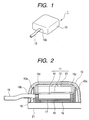
- Fig. 1 is a general perspective view of a GPS receiving antenna;
- Fig. 2 is a schematic sectional view of the GPS receiving antenna;
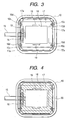
- Fig. 3 is a bottom view of the GPS receiving antenna before a seal part is formed;
- Fig. 4 is a bottom view of the GPS receiving antenna after a seal part is formed; and
- Fig. 5(a) is a schematic sectional view showing the process of attaching an antenna module;
- Fig. 5(b) is a schematic sectional view showing the process of soldering a transmission cable;
- Fig. 5(c) is a schematic sectional view showing the process of filling silicon resin;
- Fig. 5(d) is a schematic sectional view showing the process of attaching a metal plate;
- Fig. 5(e) is a schematic sectional view showing the process of attaching a magnet;
- Fig. 5(f) is a schematic sectional view showing the process of forming a seal part; and
- Fig. 6 is an exploded side view of a conventional antenna device.
-
- Now, a GPS receiving antenna will be described as an application of the invention to an antenna device.
- As shown in Figs. 1 and 2, the GPS receiving antenna 1 according to an embodiment includes a
cover member 10 generally formed in a substantially cubic shape. Thecover member 10 is produced by injection-molding a resin material having desired weather and water resistance and has an internal space for storing the elements of the GPS receiving antenna 1. Thecover member 10 has one surface opened and generally has a bowl shape. - In the internal space of the
cover member 10, anantenna module 11 for receiving radio waves transmitted from GPS satellite is stored. In theantenna module 11, areceiving antenna 13 is provided on asubstrate 12. Ashield case 14 storing the peripheral circuit of thereceiving antenna 13 is provided on the backside of the substrate 12 (on the opposite side to the surface with the receiving antenna 13). - The
substrate 12 has notches 10d in four location of the outer edge part. Theantenna module 11 has an integrally formedupright part 10a in an approximately circular shape from the inner surface of thecover member 10 to support the peripheral edge of thesubstrate 12, andengagement members 10c are provided on theupright part 10a in the positions of thesubstrate 12 corresponding to thenotches 10d. Thesubstrate 12 has thenotches 10d fitted to theengagement members 10c and provisionally fixed to the internal space of thecover member 10. - A
transmission cable 15 to output a signal included in received radio waves is extended from theantenna module 11. Thetransmission cable 15 is inserted through ahole 10b formed on one side of thecover member 10 and externally extended from thecover member 10. In this way, thetransmission cable 15 is extended from thehole 10b and therefore higher water resistance can be secured than for example the case of extending the cable through a notch. - According to the embodiment, a waterproof seal of a seal material is provided on the inner side of the
hole 10b. Fig. 3 is a view of the state before a sealing part is formed by filling a composite resin material as will be described. On the inner side of thehole 10b, aseal material 16 such as silicon resin fills the periphery of thetransmission cable 15. Theseal material 16 fills the gap between thetransmission cable 15 and thehole 10b in order to prevent water from coming in through the gap. The silicon resin is inpoured into the vicinity of thetransmission cable 15 and thehole 10b in liquid form. When the silicon resin is inpored, the silicon resin is also inpored into the gap between thetransmission cable 15 and thehole 10b. Subsequently, the silicon resin in liquid form become hardened by a heating or the like. As shown in Fig. 3, amagnet 18 is provided at the bottom (on the open side of the cover member 10) of theantenna module 11 through ametal plate 17. Themagnet 18 is positioned by theprotrusions 19 on the metal plate and firmly connected to theshield case 14 by the magnetic force. As a result, themetal plate 17 is attached as it covers theshield case 14. Themetal plate 17 is provided with fournotches 17a, and thenotches 17a are fitted to theengagement members 10c of thecover member 10 for positioning. - The GPS receiving antenna 1 includes the
magnet 18 and can surely be fixed to the roof of an automobile by the magnetic force of themagnet 18. Note that the GPS receiving antenna 1 may be fixed to the automobile by another fixing member rather than using themagnet 18, but the antenna fixed by themagnet 18 can be detached/attached from/to the automobile extremely easily. In the GPS receiving antenna 1, the shape and number of themagnets 18 are not particularly specified. As shown in Fig. 4, in the GPS receiving antenna 1, thecover member 10 has its open surface closed by themetal plate 17 and themagnet 18 as theantenna module 11 is stored in the internal space of thecover member 10, and theseal part 20 filled with a composite resin material is formed. Note that in Figs. 2 and 4, the part where theseal part 20 is formed by filling the composite resin material is diagonally shaded. Theseal part 20 is made of a composite resin material such as polyester polymer filled and solidified by hot melt process and the seal part encloses theantenna module 11 in the internal space of thecover member 10. - In the GPS receiving antenna 1, the
seal part 20 is formed in this way, so that high water resistance is secured and theantenna module 11 can be prevented from degrading such as rusting if it is exposed to the weather for a long period of time. - The GPS receiving antenna 1 is made waterproof by the
seal part 20 filled with the composite resin material. Therefore, the antenna has a considerably reduced number of parts and a simplified structure as compared to the conventional GPS receiving antenna. Consequently, the parts cost and assembly cost can considerably be reduced and the overall cost can be reduced. Note that any arbitrary material other than polyester polymer may be used as the composite resin material to form theseal part 20 in consideration of how easily the material can be solidified and the fluidity of the material when the material is melted as long as desired water resistance can be secured. - The
seal part 20 does not have to be filled and solidified by the hot melt process, while the process is desirably employed in view of readiness in filling or the necessary man hours. The open side (side facing the outside) of thecover member 10 in theseal part 20 is preferably formed to be flat. In this way, the antenna is easily provided on a relatively flat surface such as on the roof of an automobile. - Fig. 4 shows an example of how the
magnet 18 is set in theseal part 20 while the bottom of themagnet 18 faces the outside from theseal part 20, but themagnet 18 may completely be surrounded by theseal part 20. In this way, the water resistance by theseal part 20 can be improved. However, in consideration of the fixing strength of themagnet 18 to the surface by the magnetic force of themagnet 18, it is preferable that the bottom of themagnet 18 is exposed through theseal part 20. - The GPS receiving antenna 1 may be provided with a
sheet type member 21 in approximately the same shape as the bottom of thecover member 10 on the outer side of theseal part 20 as shown in Fig. 2 in order to prevent the roof of the automobile from being damaged by themagnet 18 or the like exposed at the bottom. Thesheet type member 21 may be formed for example by polyethylene terephthalate (PET). In this case, an identifier tag similar to that of the conventional GPS receiving antenna may be provided between theseal part 20 and thesheet type member 21, so that the content inscribed on the identifier tag may be read through the transparent part formed on thesheet type member 21. - The method of assembling the GPS receiving antenna 1 will be described. Figs. 5(a) to 5(f) show a series of steps in the assembling process. In producing the GPS receiving antenna 1, the
antenna module 11 is stored and fitted in thecase member 10 as shown in Fig. 5(a). Then, as shown in Fig. 5(b), thetransmission cable 15 is inserted from thehole 10b of thecase member 10 and soldering is carried out. The soldering is carried out in a workinghole 14a provided in theshield case 14 corresponding to the connection part between thesubstrate 12 and thetransmission cable 15. - Now, as shown in Fig. 5(c), silicon resin is filled around the
connected transmission cable 15 in the vicinity of thehole 10b of thecase member 10, and theseal member 16 is formed. Then, as shown in Fig. 5(d), themetal plate 17 is attached to theshield case 14 with a length of double-faced adhesive tape 22, and as shown in Fig. 5(e), themagnet 18 is attached to themetal plate 17 by the magnetic force as it is positioned by theprotrusions 19 of themetal plate 17. Finally, as shown in Fig. 5(f), a hot melt adhesive or the like is filled within the open side of thecase member 10 to form theseal part 20, and the GPS receiving antenna 1 is completed.
Claims (5)
- An antenna device, comprising:an antenna module, adapted to receive a radio wave;a signal cable, connected to the antenna module;an antenna case, defining an inner space to accommodate the antenna module therein, the antenna case including:a first case member, formed with a hole through which the signal cable is led out and an opening; anda second case member, coupled to the first case member so as to close the opening; anda sealing member, sealing a space between the hole and an outer periphery of the signal cable.
- The antenna device according to claim 1, wherein the sealing member is comprised of a silicon resin.
- The antenna device according to claim 1, wherein the second case member is provided as a metal plate and formed with a projection positioning a magnet for attaching the antenna device to an external member.
- The antenna device according to claim 2, wherein after the second case member is attached to the first case member, a composite resin material is filled to seal a bottom surface side of the first cover member.
- The antenna device according to claim 4, wherein the composite resin material is comprised of a hot melt adhesive.
Applications Claiming Priority (2)
| Application Number | Priority Date | Filing Date | Title |
|---|---|---|---|
| JP2003342105 | 2003-09-30 | ||
| JP2003342105A JP4120552B2 (en) | 2003-09-30 | 2003-09-30 | Antenna device |
Publications (2)
| Publication Number | Publication Date |
|---|---|
| EP1521331A2 true EP1521331A2 (en) | 2005-04-06 |
| EP1521331A3 EP1521331A3 (en) | 2007-10-17 |
Family
ID=34309085
Family Applications (1)
| Application Number | Title | Priority Date | Filing Date |
|---|---|---|---|
| EP04015354A Withdrawn EP1521331A3 (en) | 2003-09-30 | 2004-06-30 | Antena device |
Country Status (4)
| Country | Link |
|---|---|
| US (1) | US7187333B2 (en) |
| EP (1) | EP1521331A3 (en) |
| JP (1) | JP4120552B2 (en) |
| CN (1) | CN1604386B (en) |
Cited By (17)
| Publication number | Priority date | Publication date | Assignee | Title |
|---|---|---|---|---|
| WO2010039212A1 (en) * | 2008-10-02 | 2010-04-08 | Certusview Technologies, Llc | Methods, apparatus, and systems for generating electronic records of locate and marking operations, and combined locate and marking apparatus for same |
| WO2010039242A2 (en) * | 2008-10-02 | 2010-04-08 | Certusview Technologies, Llc | Methods and apparatus for generating electronic records of locate operations |
| US8060304B2 (en) | 2007-04-04 | 2011-11-15 | Certusview Technologies, Llc | Marking system and method |
| US8280631B2 (en) | 2008-10-02 | 2012-10-02 | Certusview Technologies, Llc | Methods and apparatus for generating an electronic record of a marking operation based on marking device actuations |
| US8301380B2 (en) | 2008-10-02 | 2012-10-30 | Certusview Technologies, Llp | Systems and methods for generating electronic records of locate and marking operations |
| US8401791B2 (en) | 2007-03-13 | 2013-03-19 | Certusview Technologies, Llc | Methods for evaluating operation of marking apparatus |
| US8442766B2 (en) | 2008-10-02 | 2013-05-14 | Certusview Technologies, Llc | Marking apparatus having enhanced features for underground facility marking operations, and associated methods and systems |
| US8473209B2 (en) | 2007-03-13 | 2013-06-25 | Certusview Technologies, Llc | Marking apparatus and marking methods using marking dispenser with machine-readable ID mechanism |
| US8478523B2 (en) | 2007-03-13 | 2013-07-02 | Certusview Technologies, Llc | Marking apparatus and methods for creating an electronic record of marking apparatus operations |
| US8527308B2 (en) | 2008-10-02 | 2013-09-03 | Certusview Technologies, Llc | Methods and apparatus for overlaying electronic locate information on facilities map information and/or other image information displayed on a locate device |
| US8620587B2 (en) | 2008-10-02 | 2013-12-31 | Certusview Technologies, Llc | Methods, apparatus, and systems for generating electronic records of locate and marking operations, and combined locate and marking apparatus for same |
| US8620616B2 (en) | 2009-08-20 | 2013-12-31 | Certusview Technologies, Llc | Methods and apparatus for assessing marking operations based on acceleration information |
| US8620572B2 (en) | 2009-08-20 | 2013-12-31 | Certusview Technologies, Llc | Marking device with transmitter for triangulating location during locate operations |
| US8626571B2 (en) | 2009-02-11 | 2014-01-07 | Certusview Technologies, Llc | Management system, and associated methods and apparatus, for dispatching tickets, receiving field information, and performing a quality assessment for underground facility locate and/or marking operations |
| US8749239B2 (en) | 2008-10-02 | 2014-06-10 | Certusview Technologies, Llc | Locate apparatus having enhanced features for underground facility locate operations, and associated methods and systems |
| US8965700B2 (en) | 2008-10-02 | 2015-02-24 | Certusview Technologies, Llc | Methods and apparatus for generating an electronic record of environmental landmarks based on marking device actuations |
| US9097522B2 (en) | 2009-08-20 | 2015-08-04 | Certusview Technologies, Llc | Methods and marking devices with mechanisms for indicating and/or detecting marking material color |
Families Citing this family (12)
| Publication number | Priority date | Publication date | Assignee | Title |
|---|---|---|---|---|
| JP4513964B2 (en) * | 2005-02-23 | 2010-07-28 | ミツミ電機株式会社 | Planar antenna |
| JP4747628B2 (en) * | 2005-03-28 | 2011-08-17 | 日産自動車株式会社 | Automotive antenna |
| JP2008078720A (en) | 2006-09-19 | 2008-04-03 | Mitsumi Electric Co Ltd | Antenna device |
| JP4807204B2 (en) | 2006-09-19 | 2011-11-02 | ミツミ電機株式会社 | Antenna device |
| JP2009065388A (en) * | 2007-09-05 | 2009-03-26 | Toshiba Corp | Wireless communication device and antenna device |
| US8478617B2 (en) | 2008-10-02 | 2013-07-02 | Certusview Technologies, Llc | Methods and apparatus for generating alerts on a locate device, based on comparing electronic locate information to facilities map information and/or other image information |
| CA2771286C (en) | 2009-08-11 | 2016-08-30 | Certusview Technologies, Llc | Locating equipment communicatively coupled to or equipped with a mobile/portable device |
| CN102916250B (en) * | 2012-10-31 | 2015-04-22 | 北京希格诺科技有限公司 | Locomotive antenna packaging device and packaging method thereof |
| US9673517B2 (en) * | 2014-04-30 | 2017-06-06 | Honda Motor Co., Ltd. | Vehicle radar cover assembly and method |
| US9905905B1 (en) | 2014-09-26 | 2018-02-27 | Tessco Communications Incorporated | Antenna enclosure for attachment to a handrail |
| US20170288302A1 (en) * | 2014-12-18 | 2017-10-05 | Hirschmann Car Communication Gmbh | Water-right lte antenna having pu potting |
| US10249935B2 (en) | 2017-07-30 | 2019-04-02 | Tessco Communications Incorporated | Handrail Wi-Fi enclosure |
Citations (7)
| Publication number | Priority date | Publication date | Assignee | Title |
|---|---|---|---|---|
| EP0355424A2 (en) * | 1988-07-25 | 1990-02-28 | Asahi Glass Company Ltd. | Glass antenna device for an automobile |
| GB2268032A (en) * | 1992-06-17 | 1993-12-22 | Badger Meter Inc | Utility meter transponder/antenna assembly for underground installations |
| JPH07336125A (en) * | 1994-06-13 | 1995-12-22 | Asahi Glass Co Ltd | Circuit module for automobile glass antenna and glass antenna for automobile |
| US5585809A (en) * | 1994-05-31 | 1996-12-17 | Mitsumi Electric Co., Ltd. | Antenna unit for a car navigation device |
| JP2001119165A (en) * | 1999-10-14 | 2001-04-27 | Saginomiya Seisakusho Inc | Sealing structure of lead-out part of lead wire in electronic device |
| JP2001118041A (en) * | 1999-10-18 | 2001-04-27 | Denso Corp | Id tag |
| EP1291961A1 (en) * | 2001-02-16 | 2003-03-12 | Nippon Antena Kabushiki Kaisha | On-vehicle antenna |
Family Cites Families (3)
| Publication number | Priority date | Publication date | Assignee | Title |
|---|---|---|---|---|
| US5885679A (en) * | 1994-11-18 | 1999-03-23 | Asahi Kasei Kogyo Kabushiki Kaisha | Joining structure for waterproof fabric |
| JP2001068912A (en) | 1999-08-30 | 2001-03-16 | Mitsumi Electric Co Ltd | Plane antenna |
| CN2484745Y (en) * | 2001-06-08 | 2002-04-10 | 嘉藤电气股份有限公司 | Improved remote controlled electric calling buoy |
-
2003
- 2003-09-30 JP JP2003342105A patent/JP4120552B2/en not_active Expired - Fee Related
-
2004
- 2004-05-17 CN CN2004100423197A patent/CN1604386B/en not_active Expired - Fee Related
- 2004-06-30 US US10/879,348 patent/US7187333B2/en active Active
- 2004-06-30 EP EP04015354A patent/EP1521331A3/en not_active Withdrawn
Patent Citations (7)
| Publication number | Priority date | Publication date | Assignee | Title |
|---|---|---|---|---|
| EP0355424A2 (en) * | 1988-07-25 | 1990-02-28 | Asahi Glass Company Ltd. | Glass antenna device for an automobile |
| GB2268032A (en) * | 1992-06-17 | 1993-12-22 | Badger Meter Inc | Utility meter transponder/antenna assembly for underground installations |
| US5585809A (en) * | 1994-05-31 | 1996-12-17 | Mitsumi Electric Co., Ltd. | Antenna unit for a car navigation device |
| JPH07336125A (en) * | 1994-06-13 | 1995-12-22 | Asahi Glass Co Ltd | Circuit module for automobile glass antenna and glass antenna for automobile |
| JP2001119165A (en) * | 1999-10-14 | 2001-04-27 | Saginomiya Seisakusho Inc | Sealing structure of lead-out part of lead wire in electronic device |
| JP2001118041A (en) * | 1999-10-18 | 2001-04-27 | Denso Corp | Id tag |
| EP1291961A1 (en) * | 2001-02-16 | 2003-03-12 | Nippon Antena Kabushiki Kaisha | On-vehicle antenna |
Cited By (55)
| Publication number | Priority date | Publication date | Assignee | Title |
|---|---|---|---|---|
| US8473209B2 (en) | 2007-03-13 | 2013-06-25 | Certusview Technologies, Llc | Marking apparatus and marking methods using marking dispenser with machine-readable ID mechanism |
| US8407001B2 (en) | 2007-03-13 | 2013-03-26 | Certusview Technologies, Llc | Systems and methods for using location data to electronically display dispensing of markers by a marking system or marking tool |
| US9086277B2 (en) | 2007-03-13 | 2015-07-21 | Certusview Technologies, Llc | Electronically controlled marking apparatus and methods |
| US8903643B2 (en) | 2007-03-13 | 2014-12-02 | Certusview Technologies, Llc | Hand-held marking apparatus with location tracking system and methods for logging geographic location of same |
| US8775077B2 (en) | 2007-03-13 | 2014-07-08 | Certusview Technologies, Llc | Systems and methods for using location data to electronically display dispensing of markers by a marking system or marking tool |
| US8700325B2 (en) | 2007-03-13 | 2014-04-15 | Certusview Technologies, Llc | Marking apparatus and methods for creating an electronic record of marking operations |
| US8478523B2 (en) | 2007-03-13 | 2013-07-02 | Certusview Technologies, Llc | Marking apparatus and methods for creating an electronic record of marking apparatus operations |
| US8401791B2 (en) | 2007-03-13 | 2013-03-19 | Certusview Technologies, Llc | Methods for evaluating operation of marking apparatus |
| US8060304B2 (en) | 2007-04-04 | 2011-11-15 | Certusview Technologies, Llc | Marking system and method |
| US8374789B2 (en) | 2007-04-04 | 2013-02-12 | Certusview Technologies, Llc | Systems and methods for using marking information to electronically display dispensing of markers by a marking system or marking tool |
| US8386178B2 (en) | 2007-04-04 | 2013-02-26 | Certusview Technologies, Llc | Marking system and method |
| US8478524B2 (en) | 2008-10-02 | 2013-07-02 | Certusview Technologies, Llc | Methods and apparatus for dispensing marking material in connection with underground facility marking operations based on environmental information and/or operational information |
| AU2009300322C1 (en) * | 2008-10-02 | 2013-10-17 | Certusview Technologies, Llc | Methods and apparatus for generating electronic records of locate operations |
| GB2477061B (en) * | 2008-10-02 | 2012-10-17 | Certusview Technologies Llc | Methods and apparatus for generating electronic records of locate operations |
| GB2477243B (en) * | 2008-10-02 | 2012-10-17 | Certusview Technologies Llc | Systems and methods for generating electronic records of locate marking operations |
| GB2477059B (en) * | 2008-10-02 | 2012-10-17 | Certusview Technologies Llc | Methods, apparatus, and systems for generating electronic records of locate and marking operations, and combined locate and marking apparatus for same |
| AU2009300322B2 (en) * | 2008-10-02 | 2012-10-25 | Certusview Technologies, Llc | Methods and apparatus for generating electronic records of locate operations |
| US8301380B2 (en) | 2008-10-02 | 2012-10-30 | Certusview Technologies, Llp | Systems and methods for generating electronic records of locate and marking operations |
| AU2009300322B9 (en) * | 2008-10-02 | 2012-11-08 | Certusview Technologies, Llc | Methods and apparatus for generating electronic records of locate operations |
| US8361543B2 (en) | 2008-10-02 | 2013-01-29 | Certusview Technologies, Llc | Methods and apparatus for displaying an electronic rendering of a marking operation based on an electronic record of marking information |
| AU2009300382B2 (en) * | 2008-10-02 | 2013-02-21 | Certusview Technologies, Llc | Methods, apparatus, and systems for generating electronic records of locate and marking operations, and combined locate and marking apparatus for same |
| US8442766B2 (en) | 2008-10-02 | 2013-05-14 | Certusview Technologies, Llc | Marking apparatus having enhanced features for underground facility marking operations, and associated methods and systems |
| US8457893B2 (en) | 2008-10-02 | 2013-06-04 | Certusview Technologies, Llc | Methods and apparatus for generating an electronic record of a marking operation including service-related information and/or ticket information |
| US8467969B2 (en) | 2008-10-02 | 2013-06-18 | Certusview Technologies, Llc | Marking apparatus having operational sensors for underground facility marking operations, and associated methods and systems |
| AU2009300320B2 (en) * | 2008-10-02 | 2013-06-20 | Certusview Technologies, Inc. | Systems and methods for generating electronic records of locate marking operations |
| GB2477243A (en) * | 2008-10-02 | 2011-07-27 | Certusview Technologies Llc | Systems and methods for generating electronic records of locate marking operations |
| GB2477059A (en) * | 2008-10-02 | 2011-07-20 | Certusview Technologies Llc | Methods, apparatus, and systems for generating electronic records of locate and marking operations, and combined locate and marking apparatus for same. |
| US8478525B2 (en) | 2008-10-02 | 2013-07-02 | Certusview Technologies, Llc | Methods, apparatus, and systems for analyzing use of a marking device by a technician to perform an underground facility marking operation |
| GB2477061A (en) * | 2008-10-02 | 2011-07-20 | Certusview Technologies Llc | Methods and apparatus for generating electronic records of locate operations |
| US8527308B2 (en) | 2008-10-02 | 2013-09-03 | Certusview Technologies, Llc | Methods and apparatus for overlaying electronic locate information on facilities map information and/or other image information displayed on a locate device |
| AU2009300320B8 (en) * | 2008-10-02 | 2013-10-10 | Certusview Technologies, Inc. | Systems and methods for generating electronic records of locate marking operations |
| AU2009300320A8 (en) * | 2008-10-02 | 2013-10-10 | Certusview Technologies, Inc. | Systems and methods for generating electronic records of locate marking operations |
| US8280631B2 (en) | 2008-10-02 | 2012-10-02 | Certusview Technologies, Llc | Methods and apparatus for generating an electronic record of a marking operation based on marking device actuations |
| US8612148B2 (en) | 2008-10-02 | 2013-12-17 | Certusview Technologies, Llc | Marking apparatus configured to detect out-of-tolerance conditions in connection with underground facility marking operations, and associated methods and systems |
| US8620587B2 (en) | 2008-10-02 | 2013-12-31 | Certusview Technologies, Llc | Methods, apparatus, and systems for generating electronic records of locate and marking operations, and combined locate and marking apparatus for same |
| US9542863B2 (en) | 2008-10-02 | 2017-01-10 | Certusview Technologies, Llc | Methods and apparatus for generating output data streams relating to underground utility marking operations |
| US9279900B2 (en) | 2008-10-02 | 2016-03-08 | Certusview Technologies, Llc | Systems and methods for generating electronic records of locate and marking operations |
| WO2010039212A1 (en) * | 2008-10-02 | 2010-04-08 | Certusview Technologies, Llc | Methods, apparatus, and systems for generating electronic records of locate and marking operations, and combined locate and marking apparatus for same |
| WO2010039242A3 (en) * | 2008-10-02 | 2011-01-06 | Certusview Technologies, Llc | Methods and apparatus for generating electronic records of locate operations |
| US8731830B2 (en) | 2008-10-02 | 2014-05-20 | Certusview Technologies, Llc | Marking apparatus for receiving environmental information regarding underground facility marking operations, and associated methods and systems |
| US9069094B2 (en) | 2008-10-02 | 2015-06-30 | Certusview Technologies, Llc | Locate transmitter configured to detect out-of-tolerance conditions in connection with underground facility locate operations, and associated methods and systems |
| US8749239B2 (en) | 2008-10-02 | 2014-06-10 | Certusview Technologies, Llc | Locate apparatus having enhanced features for underground facility locate operations, and associated methods and systems |
| US8766638B2 (en) | 2008-10-02 | 2014-07-01 | Certusview Technologies, Llc | Locate apparatus with location tracking system for receiving environmental information regarding underground facility marking operations, and associated methods and systems |
| WO2010039242A2 (en) * | 2008-10-02 | 2010-04-08 | Certusview Technologies, Llc | Methods and apparatus for generating electronic records of locate operations |
| US8770140B2 (en) | 2008-10-02 | 2014-07-08 | Certusview Technologies, Llc | Marking apparatus having environmental sensors and operations sensors for underground facility marking operations, and associated methods and systems |
| WO2010039240A1 (en) * | 2008-10-02 | 2010-04-08 | Certusview Technologies, Inc. | Systems and methods for generating electronic records of locate marking operations |
| US8930836B2 (en) | 2008-10-02 | 2015-01-06 | Certusview Technologies, Llc | Methods and apparatus for displaying an electronic rendering of a locate and/or marking operation using display layers |
| US8965700B2 (en) | 2008-10-02 | 2015-02-24 | Certusview Technologies, Llc | Methods and apparatus for generating an electronic record of environmental landmarks based on marking device actuations |
| US9046621B2 (en) | 2008-10-02 | 2015-06-02 | Certusview Technologies, Llc | Locate apparatus configured to detect out-of-tolerance conditions in connection with underground facility locate operations, and associated methods and systems |
| US8731999B2 (en) | 2009-02-11 | 2014-05-20 | Certusview Technologies, Llc | Management system, and associated methods and apparatus, for providing improved visibility, quality control and audit capability for underground facility locate and/or marking operations |
| US8626571B2 (en) | 2009-02-11 | 2014-01-07 | Certusview Technologies, Llc | Management system, and associated methods and apparatus, for dispatching tickets, receiving field information, and performing a quality assessment for underground facility locate and/or marking operations |
| US9185176B2 (en) | 2009-02-11 | 2015-11-10 | Certusview Technologies, Llc | Methods and apparatus for managing locate and/or marking operations |
| US9097522B2 (en) | 2009-08-20 | 2015-08-04 | Certusview Technologies, Llc | Methods and marking devices with mechanisms for indicating and/or detecting marking material color |
| US8620572B2 (en) | 2009-08-20 | 2013-12-31 | Certusview Technologies, Llc | Marking device with transmitter for triangulating location during locate operations |
| US8620616B2 (en) | 2009-08-20 | 2013-12-31 | Certusview Technologies, Llc | Methods and apparatus for assessing marking operations based on acceleration information |
Also Published As
| Publication number | Publication date |
|---|---|
| CN1604386A (en) | 2005-04-06 |
| CN1604386B (en) | 2010-07-28 |
| US7187333B2 (en) | 2007-03-06 |
| JP2005110007A (en) | 2005-04-21 |
| EP1521331A3 (en) | 2007-10-17 |
| JP4120552B2 (en) | 2008-07-16 |
| US20050068248A1 (en) | 2005-03-31 |
Similar Documents
| Publication | Publication Date | Title |
|---|---|---|
| US7187333B2 (en) | Antenna device | |
| US7218284B2 (en) | Antenna unit | |
| US7528793B2 (en) | Antenna device | |
| US7283100B2 (en) | Satellite antenna | |
| US5585809A (en) | Antenna unit for a car navigation device | |
| US5900840A (en) | Plane antenna having metal/resin bottom cover | |
| CN1825698B (en) | Antenna device and antenna water-proof structure | |
| JP2004363747A (en) | Antenna assembly | |
| CN110957612A (en) | Connecting device and electronic device comprising same | |
| US7129906B2 (en) | Antenna device | |
| US7397436B2 (en) | Protector-equipped antenna unit with drain structure | |
| CN1828994A (en) | Antenna unit | |
| JP4655438B2 (en) | Antenna device | |
| CN1825699B (en) | Antenna installation and top cover | |
| US7466280B2 (en) | Protector-equipped antenna unit using an already-existing antenna unit as an antenna body | |
| JP2005051338A (en) | Vehicle antenna and vehicle employing the same | |
| US5262814A (en) | Mounting apparatus for window in back cover of camera | |
| JP2006284235A (en) | Wearing-on-arm type electronic device | |
| WO2019208231A1 (en) | Vehicle-mounted antenna device | |
| EP4028790A1 (en) | A device for attachment to an opening of a vehicle and for covering an emitter and/or a receiver | |
| JP2000137067A (en) | Gps receiving device | |
| JPH1142977A (en) | Vehicle antenna and its manufacture | |
| US10662638B2 (en) | Construction element incorporating an electronic system and method for the production thereof | |
| JPH10275989A (en) | Packing for cable | |
| JPH09167910A (en) | Plane antenna |
Legal Events
| Date | Code | Title | Description |
|---|---|---|---|
| PUAI | Public reference made under article 153(3) epc to a published international application that has entered the european phase |
Free format text: ORIGINAL CODE: 0009012 |
|
| AK | Designated contracting states |
Kind code of ref document: A2 Designated state(s): AT BE BG CH CY CZ DE DK EE ES FI FR GB GR HU IE IT LI LU MC NL PL PT RO SE SI SK TR |
|
| AX | Request for extension of the european patent |
Extension state: AL HR LT LV MK |
|
| PUAL | Search report despatched |
Free format text: ORIGINAL CODE: 0009013 |
|
| AK | Designated contracting states |
Kind code of ref document: A3 Designated state(s): AT BE BG CH CY CZ DE DK EE ES FI FR GB GR HU IE IT LI LU MC NL PL PT RO SE SI SK TR |
|
| AX | Request for extension of the european patent |
Extension state: AL HR LT LV MK |
|
| 17P | Request for examination filed |
Effective date: 20080213 |
|
| 17Q | First examination report despatched |
Effective date: 20080313 |
|
| AKX | Designation fees paid |
Designated state(s): DE |
|
| STAA | Information on the status of an ep patent application or granted ep patent |
Free format text: STATUS: THE APPLICATION IS DEEMED TO BE WITHDRAWN |
|
| 18D | Application deemed to be withdrawn |
Effective date: 20130103 |