EP1521284A2 - Control circuit for driving an electric actuator, in particular an electric fuel injector for an internal-combustion engine - Google Patents
Control circuit for driving an electric actuator, in particular an electric fuel injector for an internal-combustion engine Download PDFInfo
- Publication number
- EP1521284A2 EP1521284A2 EP04023146A EP04023146A EP1521284A2 EP 1521284 A2 EP1521284 A2 EP 1521284A2 EP 04023146 A EP04023146 A EP 04023146A EP 04023146 A EP04023146 A EP 04023146A EP 1521284 A2 EP1521284 A2 EP 1521284A2
- Authority
- EP
- European Patent Office
- Prior art keywords
- control circuit
- activation time
- switching period
- electric actuator
- predefined
- Prior art date
- Legal status (The legal status is an assumption and is not a legal conclusion. Google has not performed a legal analysis and makes no representation as to the accuracy of the status listed.)
- Granted
Links
Images
Classifications
-
- H—ELECTRICITY
- H01—ELECTRIC ELEMENTS
- H01H—ELECTRIC SWITCHES; RELAYS; SELECTORS; EMERGENCY PROTECTIVE DEVICES
- H01H47/00—Circuit arrangements not adapted to a particular application of the relay and designed to obtain desired operating characteristics or to provide energising current
- H01H47/22—Circuit arrangements not adapted to a particular application of the relay and designed to obtain desired operating characteristics or to provide energising current for supplying energising current for relay coil
- H01H47/32—Energising current supplied by semiconductor device
- H01H47/325—Energising current supplied by semiconductor device by switching regulator
-
- F—MECHANICAL ENGINEERING; LIGHTING; HEATING; WEAPONS; BLASTING
- F02—COMBUSTION ENGINES; HOT-GAS OR COMBUSTION-PRODUCT ENGINE PLANTS
- F02D—CONTROLLING COMBUSTION ENGINES
- F02D41/00—Electrical control of supply of combustible mixture or its constituents
- F02D41/20—Output circuits, e.g. for controlling currents in command coils
-
- H—ELECTRICITY
- H01—ELECTRIC ELEMENTS
- H01F—MAGNETS; INDUCTANCES; TRANSFORMERS; SELECTION OF MATERIALS FOR THEIR MAGNETIC PROPERTIES
- H01F7/00—Magnets
- H01F7/06—Electromagnets; Actuators including electromagnets
- H01F7/08—Electromagnets; Actuators including electromagnets with armatures
- H01F7/18—Circuit arrangements for obtaining desired operating characteristics, e.g. for slow operation, for sequential energisation of windings, for high-speed energisation of windings
- H01F7/1844—Monitoring or fail-safe circuits
-
- H—ELECTRICITY
- H02—GENERATION; CONVERSION OR DISTRIBUTION OF ELECTRIC POWER
- H02M—APPARATUS FOR CONVERSION BETWEEN AC AND AC, BETWEEN AC AND DC, OR BETWEEN DC AND DC, AND FOR USE WITH MAINS OR SIMILAR POWER SUPPLY SYSTEMS; CONVERSION OF DC OR AC INPUT POWER INTO SURGE OUTPUT POWER; CONTROL OR REGULATION THEREOF
- H02M3/00—Conversion of DC power input into DC power output
- H02M3/02—Conversion of DC power input into DC power output without intermediate conversion into AC
- H02M3/04—Conversion of DC power input into DC power output without intermediate conversion into AC by static converters
- H02M3/10—Conversion of DC power input into DC power output without intermediate conversion into AC by static converters using discharge tubes with control electrode or semiconductor devices with control electrode
- H02M3/145—Conversion of DC power input into DC power output without intermediate conversion into AC by static converters using discharge tubes with control electrode or semiconductor devices with control electrode using devices of a triode or transistor type requiring continuous application of a control signal
- H02M3/155—Conversion of DC power input into DC power output without intermediate conversion into AC by static converters using discharge tubes with control electrode or semiconductor devices with control electrode using devices of a triode or transistor type requiring continuous application of a control signal using semiconductor devices only
- H02M3/156—Conversion of DC power input into DC power output without intermediate conversion into AC by static converters using discharge tubes with control electrode or semiconductor devices with control electrode using devices of a triode or transistor type requiring continuous application of a control signal using semiconductor devices only with automatic control of output voltage or current, e.g. switching regulators
-
- F—MECHANICAL ENGINEERING; LIGHTING; HEATING; WEAPONS; BLASTING
- F02—COMBUSTION ENGINES; HOT-GAS OR COMBUSTION-PRODUCT ENGINE PLANTS
- F02D—CONTROLLING COMBUSTION ENGINES
- F02D41/00—Electrical control of supply of combustible mixture or its constituents
- F02D41/20—Output circuits, e.g. for controlling currents in command coils
- F02D2041/2003—Output circuits, e.g. for controlling currents in command coils using means for creating a boost voltage, i.e. generation or use of a voltage higher than the battery voltage, e.g. to speed up injector opening
- F02D2041/2013—Output circuits, e.g. for controlling currents in command coils using means for creating a boost voltage, i.e. generation or use of a voltage higher than the battery voltage, e.g. to speed up injector opening by using a boost voltage source
-
- F—MECHANICAL ENGINEERING; LIGHTING; HEATING; WEAPONS; BLASTING
- F02—COMBUSTION ENGINES; HOT-GAS OR COMBUSTION-PRODUCT ENGINE PLANTS
- F02D—CONTROLLING COMBUSTION ENGINES
- F02D41/00—Electrical control of supply of combustible mixture or its constituents
- F02D41/20—Output circuits, e.g. for controlling currents in command coils
- F02D2041/202—Output circuits, e.g. for controlling currents in command coils characterised by the control of the circuit
- F02D2041/2024—Output circuits, e.g. for controlling currents in command coils characterised by the control of the circuit the control switching a load after time-on and time-off pulses
- F02D2041/2027—Control of the current by pulse width modulation or duty cycle control
-
- F—MECHANICAL ENGINEERING; LIGHTING; HEATING; WEAPONS; BLASTING
- F02—COMBUSTION ENGINES; HOT-GAS OR COMBUSTION-PRODUCT ENGINE PLANTS
- F02D—CONTROLLING COMBUSTION ENGINES
- F02D41/00—Electrical control of supply of combustible mixture or its constituents
- F02D41/20—Output circuits, e.g. for controlling currents in command coils
- F02D2041/202—Output circuits, e.g. for controlling currents in command coils characterised by the control of the circuit
- F02D2041/2058—Output circuits, e.g. for controlling currents in command coils characterised by the control of the circuit using information of the actual current value
-
- H—ELECTRICITY
- H01—ELECTRIC ELEMENTS
- H01F—MAGNETS; INDUCTANCES; TRANSFORMERS; SELECTION OF MATERIALS FOR THEIR MAGNETIC PROPERTIES
- H01F7/00—Magnets
- H01F7/06—Electromagnets; Actuators including electromagnets
- H01F7/08—Electromagnets; Actuators including electromagnets with armatures
- H01F7/18—Circuit arrangements for obtaining desired operating characteristics, e.g. for slow operation, for sequential energisation of windings, for high-speed energisation of windings
- H01F2007/1888—Circuit arrangements for obtaining desired operating characteristics, e.g. for slow operation, for sequential energisation of windings, for high-speed energisation of windings using pulse width modulation
Definitions
- the present invention relates to a circuit for driving an electric actuator, in particular an electric fuel injector for an internal-combustion engine.
- control circuit of the type defined in the introductory part of Claim 1.
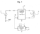
- 1 denotes a direct voltage source, for example a battery in a motor vehicle.
- the voltage source 1 has its negative pole connected to earth GND and its positive pole connected to a chopper circuit denoted overall by 2.
- the chopper circuit 2 denotes an electronic control unit designed to apply to the chopper circuit 2, for an activation time t i which is in each case predetermined and included between an initial instant t s and a final instant t e , a command signal CS essentially of the PWM (Pulse-Width Modulation) type, with a predefined ON/OFF switching period p and a variable duty cycle.
- the chopper circuit 2 causes the flow, within the electric actuator 3, of a correspondingly choppered current I having a nominal duration corresponding to the abovementioned activation time t i .
- the current choppering frequency is not particularly high so that the current has a ripple of notable amplitude.
- the duration of each fuel injection operation is controlled in an open loop, the time required for the injector to close completely depends on the instantaneous value reached by the current at the end of the electric injector activation time.
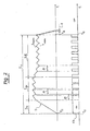
- the upper graph shows the qualitative progression of the current I in an electric injector driven with a circuit according to the prior art and the lower graph shows the progression of the command signal CS correspondingly applied to the chopper circuit associated with the electric injector.
- the current I has a rise phase of duration t r followed by a first choppering phase of the peak value, of duration tp, in turn followed by a subsequent choppering phase in the region of a maintenance value, of duration t h .
- the signal CS is high (ON) during the phase t r and then has a progression of the ON/OFF type during the phases t p and t h , with a constant switching period p and with a high duty cycle during the phase t p and low duty cycle during the phase t h .
- the command signal CS started at the initial instant t s , terminates at the final instant t e .
- the intensity of the current I may be between a minimum value I HMIN and a maximum value I HMAX .
- complete closing again of the electric injector occurs at a instant variable within a time interval E which represents the error in determination of the actual injection time.
- One object of the present invention is to provide a control circuit for driving an electric actuator, in which the current in the electric actuator is controlled in an open loop, which circuit allows the abovementioned drawback of the solutions according to the prior art to be overcome.
- control circuit according to the invention has essentially the same architecture shown schematically in Figure 1. However the control unit 4 drives the chopper circuit 2 in a different manner.
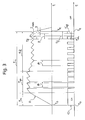
- control unit 4 is designed to determine the last whole or complete switching period included within the activation time t i of the electric actuator 3 before the final instant t e .
- This last complete switching period is indicated by P in the upper graph according to Figure 3.
- the broken lines indicate the progression of the current which would occur with a control circuit according to the prior art, while the continuous lines indicate the current progression which is achieved with a circuit according to the invention.
- a similar system of graphic representation is used in the lower graph of Figure 3, which shows the progression of the command signal CS.
- the control unit 4 determines, on the basis of one or more external control parameters, the duration of activation t i and, since the values of the other abovementioned parameters are known, may easily determine the last complete switching period P included within the activation time t i .
- control unit 4 of a control circuit is also designed to allocate in accordance with the duty cycle applied during the phase t h the final interval of the activation time t i , indicated by t f in Figure 3, which comprises the last complete period P and (any) subsequent fraction of a switching period indicated by r.
- the control unit 4 therefore drives the chopper circuit 2 during the final interval t f in a manner corresponding to allocation of this final interval performed in accordance with the abovementioned duty cycle, and hence with a command signal which during the final interval t f is "ON" for the interval indicated by t' on in Figure 3 and is "OFF” for the interval indicated by t' off in said figure.
- control system is able to achieve a notable reduction in the error during the actual activation time (actual injection time) also with real, i.e. actual, progressions of the current I.
Landscapes
- Engineering & Computer Science (AREA)
- Power Engineering (AREA)
- Physics & Mathematics (AREA)
- Electromagnetism (AREA)
- Chemical & Material Sciences (AREA)
- Combustion & Propulsion (AREA)
- Mechanical Engineering (AREA)
- General Engineering & Computer Science (AREA)
- Electrical Control Of Air Or Fuel Supplied To Internal-Combustion Engine (AREA)
- Fuel-Injection Apparatus (AREA)
- Stereo-Broadcasting Methods (AREA)
Abstract
- a direct voltage source (1);
- a chopper circuit (2) arranged between the source (1) and an electric actuator (3); and
- an electronic control circuit (4) designed to apply to the chopper circuit (2) a command signal (CS) of the PWM type, with a predefined ON/OFF switching period (P) and a predetermined duty cycle, for a likewise predefined activation time (ti), so as to produce a flow, within the electric actuator (3), of a correspondingly choppered current (I) having a nominal duration corresponding to the activation time (ti).
- detect the last whole or complete switching period (P) included within the activation time (ti);
- allocate in accordance with a predefined duty cycle the final interval (tf) comprising said last complete switching period (P) and any subsequent fraction of a switching period (R) included within said activation time (ti), and
- correspondingly drive the chopper circuit (2) in this final interval (tf).

Description
Claims (1)
- Control circuit for driving an electric actuator (3), comprising:the control circuit being characterized in that the abovementioned unit (4) is arranged to:a direct voltage source (1);a chopper circuit (2) arranged between said source (1) and the electric actuator (3); andan electronic control circuit (4) designed to apply to the chopper circuit (2) a command signal (CS) essentially of the PWM type, with a predefined ON/OFF switching period (P) and a predetermined duty cycle, for a likewise predefined activation time (ti), so as to produce a flow, within the electric actuator (3), of a correspondingly choppered current (I) having a nominal duration corresponding to said activation time (ti);detect the last whole or complete switching period (P) included within the activation time (ti);allocate in accordance with a predefined duty cycle the final interval (tf) comprising said last complete switching period (P) and any subsequent fraction of a switching period (R) included within said activation time (ti), andcorrespondingly drive the chopper circuit (2) in said final interval (tf).
Applications Claiming Priority (2)
| Application Number | Priority Date | Filing Date | Title |
|---|---|---|---|
| IT000778A ITTO20030778A1 (en) | 2003-10-03 | 2003-10-03 | CONTROL CIRCUIT FOR THE PILOT OF A |
| ITTO20030778 | 2003-10-03 |
Publications (3)
| Publication Number | Publication Date |
|---|---|
| EP1521284A2 true EP1521284A2 (en) | 2005-04-06 |
| EP1521284A3 EP1521284A3 (en) | 2009-04-15 |
| EP1521284B1 EP1521284B1 (en) | 2010-12-01 |
Family
ID=34308165
Family Applications (1)
| Application Number | Title | Priority Date | Filing Date |
|---|---|---|---|
| EP04023146A Expired - Lifetime EP1521284B1 (en) | 2003-10-03 | 2004-09-29 | Control circuit for driving an electric actuator, in particular an electric fuel injector for an internal-combustion engine |
Country Status (6)
| Country | Link |
|---|---|
| US (1) | US7224565B2 (en) |
| EP (1) | EP1521284B1 (en) |
| JP (1) | JP4291245B2 (en) |
| AT (1) | ATE490545T1 (en) |
| DE (1) | DE602004030307D1 (en) |
| IT (1) | ITTO20030778A1 (en) |
Cited By (3)
| Publication number | Priority date | Publication date | Assignee | Title |
|---|---|---|---|---|
| EP2131963A4 (en) * | 2007-03-06 | 2013-12-18 | Spraying Systems Co | Optimized method to drive electric spray guns |
| WO2014167089A1 (en) * | 2013-04-12 | 2014-10-16 | Schneider Electric Industries Sas | Electrical contactor and method for controlling an electromagnetic coil in such a contactor |
| GB2520084A (en) * | 2013-11-11 | 2015-05-13 | Gm Global Tech Operations Inc | Method of controlling a solenoid valve |
Families Citing this family (7)
| Publication number | Priority date | Publication date | Assignee | Title |
|---|---|---|---|---|
| US7527040B2 (en) * | 2005-12-21 | 2009-05-05 | Boondocker Llc | Fuel injection performance enhancing controller |
| US20110077200A1 (en) * | 2006-12-06 | 2011-03-31 | Somaxon Pharmaceuticals, Inc. | Combination therapy using low-dose doxepin for the improvement of sleep |
| US8478509B1 (en) | 2009-08-07 | 2013-07-02 | William E. Kirkpatrick | Method and apparatus for varying the duration of a fuel injector cycle pulse length |
| US20110149458A1 (en) * | 2009-12-17 | 2011-06-23 | Caterpillar Inc. | Systems and methods for detecting solenoid armature movement |
| DE102011086957A1 (en) * | 2011-11-23 | 2013-05-23 | Robert Bosch Gmbh | Method for controlling a solenoid valve, and computer program and control and / or regulating device |
| US20140000576A1 (en) * | 2012-06-29 | 2014-01-02 | Continental Automotive Systems, Inc. | Chassis mount multi-input h-bridge electrical harness |
| JP2021085378A (en) * | 2019-11-28 | 2021-06-03 | 株式会社デンソー | Injection control device |
Family Cites Families (9)
| Publication number | Priority date | Publication date | Assignee | Title |
|---|---|---|---|---|
| US3863118A (en) * | 1973-01-26 | 1975-01-28 | Warner Electric Brake & Clutch | Closed-loop speed control for step motors |
| DE2828678A1 (en) * | 1978-06-30 | 1980-04-17 | Bosch Gmbh Robert | METHOD AND DEVICE FOR OPERATING AN ELECTROMAGNETIC CONSUMER, IN PARTICULAR AN INJECTION VALVE IN INTERNAL COMBUSTION ENGINES |
| JPS56132196A (en) * | 1980-03-19 | 1981-10-16 | Seiko Epson Corp | Driving system for stepping motor |
| JPS5765867A (en) * | 1980-10-09 | 1982-04-21 | Toshiba Corp | Ignition device |
| US4600868A (en) * | 1983-05-09 | 1986-07-15 | Bryant Lawrence M | Open loop acceleration/deceleration control for disk drive stepper motors |
| DE3722527A1 (en) * | 1987-07-08 | 1989-01-19 | Vdo Schindling | Method and circuit arrangement for driving a fuel injection valve |
| JP3058699B2 (en) * | 1990-02-16 | 2000-07-04 | テキサス インスツルメンツ インコーポレイテツド | Negative voltage clamp circuit for current control in inductive loads |
| US5615064A (en) * | 1994-10-03 | 1997-03-25 | International Business Machines Corporation | Pulsed current velocity controlled head load method and apparatus which uses the back EMF to control the generation of head actuator driving pulses |
| US5930103A (en) * | 1998-03-02 | 1999-07-27 | Motorola, Inc. | Control circuit for an electromechanical device |
-
2003
- 2003-10-03 IT IT000778A patent/ITTO20030778A1/en unknown
-
2004
- 2004-09-29 AT AT04023146T patent/ATE490545T1/en not_active IP Right Cessation
- 2004-09-29 DE DE602004030307T patent/DE602004030307D1/en not_active Expired - Lifetime
- 2004-09-29 EP EP04023146A patent/EP1521284B1/en not_active Expired - Lifetime
- 2004-10-01 JP JP2004289799A patent/JP4291245B2/en not_active Expired - Fee Related
- 2004-10-04 US US10/956,071 patent/US7224565B2/en not_active Expired - Fee Related
Cited By (5)
| Publication number | Priority date | Publication date | Assignee | Title |
|---|---|---|---|---|
| EP2131963A4 (en) * | 2007-03-06 | 2013-12-18 | Spraying Systems Co | Optimized method to drive electric spray guns |
| WO2014167089A1 (en) * | 2013-04-12 | 2014-10-16 | Schneider Electric Industries Sas | Electrical contactor and method for controlling an electromagnetic coil in such a contactor |
| FR3004581A1 (en) * | 2013-04-12 | 2014-10-17 | Schneider Electric Ind Sas | ELECTRICAL CONTACTOR AND METHOD FOR CONTROLLING AN ELECTROMAGNETIC COIL IN SUCH A CONTACTOR |
| GB2520084A (en) * | 2013-11-11 | 2015-05-13 | Gm Global Tech Operations Inc | Method of controlling a solenoid valve |
| US9869263B2 (en) | 2013-11-11 | 2018-01-16 | GM Global Technology Operations LLC | Method of controlling a solenoid valve |
Also Published As
| Publication number | Publication date |
|---|---|
| US20050111160A1 (en) | 2005-05-26 |
| ATE490545T1 (en) | 2010-12-15 |
| DE602004030307D1 (en) | 2011-01-13 |
| EP1521284B1 (en) | 2010-12-01 |
| US7224565B2 (en) | 2007-05-29 |
| ITTO20030778A1 (en) | 2005-04-04 |
| JP2005121015A (en) | 2005-05-12 |
| EP1521284A3 (en) | 2009-04-15 |
| JP4291245B2 (en) | 2009-07-08 |
Similar Documents
| Publication | Publication Date | Title |
|---|---|---|
| US7777587B2 (en) | Minimum pulse width for pulse width modulation control | |
| EP2119009B1 (en) | Circuit arrangement and method for operating an inductive load | |
| EP1521284A2 (en) | Control circuit for driving an electric actuator, in particular an electric fuel injector for an internal-combustion engine | |
| JP2014055571A (en) | Fuel injection control device | |
| KR20150119872A (en) | Method for controlling an injection process of a magnetic injector | |
| US5835330A (en) | Method and device for driving an electromagnetic consumer | |
| EP1653066B1 (en) | Device for controlling fuel electro-injectors and electrovalves in an internal-combustion engine, and method of operating the same. | |
| JP2012029312A (en) | Operation method of device for controlling electric actuator in optimal operation current distribution | |
| CN107949693A (en) | Injector driving increasing apparatus | |
| CN114320633B (en) | Solenoid valve driver | |
| KR100921098B1 (en) | How to control high voltage relay for hybrid vehicle | |
| US10270373B2 (en) | Method for controlling the current of an inductive load | |
| US20190376612A1 (en) | Pwm control for electromagnetic valves | |
| US9777864B2 (en) | Method and device for controlling a solenoid actuator | |
| CN104775926B (en) | Method and circuit arrangement for actuating injection valves of, in particular, externally ignited internal combustion engines | |
| EP1793484B1 (en) | A method and device for driving power converters | |
| US11225925B2 (en) | Injection control device | |
| JP4804916B2 (en) | Booster | |
| JPS5936403B2 (en) | Drive circuit for electromagnetic coil in printer hammer drive magnet | |
| US12261564B2 (en) | Method for operating a DC motor | |
| US20250337343A1 (en) | Device and method for providing an activation signal for a pulse width modulation, power converter and electric drive system | |
| EP1657726A1 (en) | Control circuit and method for a proportional solenoid valve, particularly for use on motor vehicles | |
| KR20090032816A (en) | Pick and hold type injector control device of car | |
| JP4103677B2 (en) | Solenoid dither current control circuit | |
| JP4432624B2 (en) | Actuator drive circuit |
Legal Events
| Date | Code | Title | Description |
|---|---|---|---|
| PUAI | Public reference made under article 153(3) epc to a published international application that has entered the european phase |
Free format text: ORIGINAL CODE: 0009012 |
|
| AK | Designated contracting states |
Kind code of ref document: A2 Designated state(s): AT BE BG CH CY CZ DE DK EE ES FI FR GB GR HU IE IT LI LU MC NL PL PT RO SE SI SK TR |
|
| AX | Request for extension of the european patent |
Extension state: AL HR LT LV MK |
|
| 17P | Request for examination filed |
Effective date: 20060510 |
|
| PUAL | Search report despatched |
Free format text: ORIGINAL CODE: 0009013 |
|
| AK | Designated contracting states |
Kind code of ref document: A3 Designated state(s): AT BE BG CH CY CZ DE DK EE ES FI FR GB GR HU IE IT LI LU MC NL PL PT RO SE SI SK TR |
|
| AX | Request for extension of the european patent |
Extension state: AL HR LT LV MK |
|
| GRAP | Despatch of communication of intention to grant a patent |
Free format text: ORIGINAL CODE: EPIDOSNIGR1 |
|
| AKX | Designation fees paid |
Designated state(s): AT BE BG CH CY CZ DE DK EE ES FI FR GB GR HU IE IT LI LU MC NL PL PT RO SE SI SK TR |
|
| GRAS | Grant fee paid |
Free format text: ORIGINAL CODE: EPIDOSNIGR3 |
|
| GRAA | (expected) grant |
Free format text: ORIGINAL CODE: 0009210 |
|
| AK | Designated contracting states |
Kind code of ref document: B1 Designated state(s): AT BE BG CH CY CZ DE DK EE ES FI FR GB GR HU IE IT LI LU MC NL PL PT RO SE SI SK TR |
|
| REG | Reference to a national code |
Ref country code: GB Ref legal event code: FG4D |
|
| REG | Reference to a national code |
Ref country code: CH Ref legal event code: EP |
|
| REG | Reference to a national code |
Ref country code: IE Ref legal event code: FG4D |
|
| REF | Corresponds to: |
Ref document number: 602004030307 Country of ref document: DE Date of ref document: 20110113 Kind code of ref document: P |
|
| REG | Reference to a national code |
Ref country code: NL Ref legal event code: VDEP Effective date: 20101201 |
|
| PG25 | Lapsed in a contracting state [announced via postgrant information from national office to epo] |
Ref country code: NL Free format text: LAPSE BECAUSE OF FAILURE TO SUBMIT A TRANSLATION OF THE DESCRIPTION OR TO PAY THE FEE WITHIN THE PRESCRIBED TIME-LIMIT Effective date: 20101201 Ref country code: CY Free format text: LAPSE BECAUSE OF FAILURE TO SUBMIT A TRANSLATION OF THE DESCRIPTION OR TO PAY THE FEE WITHIN THE PRESCRIBED TIME-LIMIT Effective date: 20101201 Ref country code: FI Free format text: LAPSE BECAUSE OF FAILURE TO SUBMIT A TRANSLATION OF THE DESCRIPTION OR TO PAY THE FEE WITHIN THE PRESCRIBED TIME-LIMIT Effective date: 20101201 Ref country code: BG Free format text: LAPSE BECAUSE OF FAILURE TO SUBMIT A TRANSLATION OF THE DESCRIPTION OR TO PAY THE FEE WITHIN THE PRESCRIBED TIME-LIMIT Effective date: 20110301 Ref country code: SE Free format text: LAPSE BECAUSE OF FAILURE TO SUBMIT A TRANSLATION OF THE DESCRIPTION OR TO PAY THE FEE WITHIN THE PRESCRIBED TIME-LIMIT Effective date: 20101201 Ref country code: AT Free format text: LAPSE BECAUSE OF FAILURE TO SUBMIT A TRANSLATION OF THE DESCRIPTION OR TO PAY THE FEE WITHIN THE PRESCRIBED TIME-LIMIT Effective date: 20101201 Ref country code: SI Free format text: LAPSE BECAUSE OF FAILURE TO SUBMIT A TRANSLATION OF THE DESCRIPTION OR TO PAY THE FEE WITHIN THE PRESCRIBED TIME-LIMIT Effective date: 20101201 |
|
| PG25 | Lapsed in a contracting state [announced via postgrant information from national office to epo] |
Ref country code: GR Free format text: LAPSE BECAUSE OF FAILURE TO SUBMIT A TRANSLATION OF THE DESCRIPTION OR TO PAY THE FEE WITHIN THE PRESCRIBED TIME-LIMIT Effective date: 20110302 |
|
| PG25 | Lapsed in a contracting state [announced via postgrant information from national office to epo] |
Ref country code: BE Free format text: LAPSE BECAUSE OF FAILURE TO SUBMIT A TRANSLATION OF THE DESCRIPTION OR TO PAY THE FEE WITHIN THE PRESCRIBED TIME-LIMIT Effective date: 20101201 Ref country code: ES Free format text: LAPSE BECAUSE OF FAILURE TO SUBMIT A TRANSLATION OF THE DESCRIPTION OR TO PAY THE FEE WITHIN THE PRESCRIBED TIME-LIMIT Effective date: 20110312 Ref country code: EE Free format text: LAPSE BECAUSE OF FAILURE TO SUBMIT A TRANSLATION OF THE DESCRIPTION OR TO PAY THE FEE WITHIN THE PRESCRIBED TIME-LIMIT Effective date: 20101201 Ref country code: PT Free format text: LAPSE BECAUSE OF FAILURE TO SUBMIT A TRANSLATION OF THE DESCRIPTION OR TO PAY THE FEE WITHIN THE PRESCRIBED TIME-LIMIT Effective date: 20110401 Ref country code: CZ Free format text: LAPSE BECAUSE OF FAILURE TO SUBMIT A TRANSLATION OF THE DESCRIPTION OR TO PAY THE FEE WITHIN THE PRESCRIBED TIME-LIMIT Effective date: 20101201 |
|
| PG25 | Lapsed in a contracting state [announced via postgrant information from national office to epo] |
Ref country code: PL Free format text: LAPSE BECAUSE OF FAILURE TO SUBMIT A TRANSLATION OF THE DESCRIPTION OR TO PAY THE FEE WITHIN THE PRESCRIBED TIME-LIMIT Effective date: 20101201 Ref country code: SK Free format text: LAPSE BECAUSE OF FAILURE TO SUBMIT A TRANSLATION OF THE DESCRIPTION OR TO PAY THE FEE WITHIN THE PRESCRIBED TIME-LIMIT Effective date: 20101201 Ref country code: RO Free format text: LAPSE BECAUSE OF FAILURE TO SUBMIT A TRANSLATION OF THE DESCRIPTION OR TO PAY THE FEE WITHIN THE PRESCRIBED TIME-LIMIT Effective date: 20101201 |
|
| PLBE | No opposition filed within time limit |
Free format text: ORIGINAL CODE: 0009261 |
|
| STAA | Information on the status of an ep patent application or granted ep patent |
Free format text: STATUS: NO OPPOSITION FILED WITHIN TIME LIMIT |
|
| PG25 | Lapsed in a contracting state [announced via postgrant information from national office to epo] |
Ref country code: DK Free format text: LAPSE BECAUSE OF FAILURE TO SUBMIT A TRANSLATION OF THE DESCRIPTION OR TO PAY THE FEE WITHIN THE PRESCRIBED TIME-LIMIT Effective date: 20101201 |
|
| 26N | No opposition filed |
Effective date: 20110902 |
|
| REG | Reference to a national code |
Ref country code: DE Ref legal event code: R097 Ref document number: 602004030307 Country of ref document: DE Effective date: 20110902 |
|
| PG25 | Lapsed in a contracting state [announced via postgrant information from national office to epo] |
Ref country code: MC Free format text: LAPSE BECAUSE OF NON-PAYMENT OF DUE FEES Effective date: 20110930 |
|
| REG | Reference to a national code |
Ref country code: CH Ref legal event code: PL |
|
| GBPC | Gb: european patent ceased through non-payment of renewal fee |
Effective date: 20110929 |
|
| REG | Reference to a national code |
Ref country code: IE Ref legal event code: MM4A |
|
| PG25 | Lapsed in a contracting state [announced via postgrant information from national office to epo] |
Ref country code: CH Free format text: LAPSE BECAUSE OF NON-PAYMENT OF DUE FEES Effective date: 20110930 Ref country code: IE Free format text: LAPSE BECAUSE OF NON-PAYMENT OF DUE FEES Effective date: 20110929 Ref country code: LI Free format text: LAPSE BECAUSE OF NON-PAYMENT OF DUE FEES Effective date: 20110930 |
|
| PG25 | Lapsed in a contracting state [announced via postgrant information from national office to epo] |
Ref country code: GB Free format text: LAPSE BECAUSE OF NON-PAYMENT OF DUE FEES Effective date: 20110929 |
|
| PG25 | Lapsed in a contracting state [announced via postgrant information from national office to epo] |
Ref country code: LU Free format text: LAPSE BECAUSE OF NON-PAYMENT OF DUE FEES Effective date: 20110929 |
|
| PG25 | Lapsed in a contracting state [announced via postgrant information from national office to epo] |
Ref country code: TR Free format text: LAPSE BECAUSE OF FAILURE TO SUBMIT A TRANSLATION OF THE DESCRIPTION OR TO PAY THE FEE WITHIN THE PRESCRIBED TIME-LIMIT Effective date: 20101201 |
|
| PG25 | Lapsed in a contracting state [announced via postgrant information from national office to epo] |
Ref country code: HU Free format text: LAPSE BECAUSE OF FAILURE TO SUBMIT A TRANSLATION OF THE DESCRIPTION OR TO PAY THE FEE WITHIN THE PRESCRIBED TIME-LIMIT Effective date: 20101201 |
|
| REG | Reference to a national code |
Ref country code: FR Ref legal event code: PLFP Year of fee payment: 12 |
|
| PGFP | Annual fee paid to national office [announced via postgrant information from national office to epo] |
Ref country code: IT Payment date: 20150911 Year of fee payment: 12 |
|
| PGFP | Annual fee paid to national office [announced via postgrant information from national office to epo] |
Ref country code: DE Payment date: 20151130 Year of fee payment: 12 |
|
| PGFP | Annual fee paid to national office [announced via postgrant information from national office to epo] |
Ref country code: FR Payment date: 20150930 Year of fee payment: 12 |
|
| REG | Reference to a national code |
Ref country code: DE Ref legal event code: R119 Ref document number: 602004030307 Country of ref document: DE |
|
| REG | Reference to a national code |
Ref country code: FR Ref legal event code: ST Effective date: 20170531 |
|
| PG25 | Lapsed in a contracting state [announced via postgrant information from national office to epo] |
Ref country code: FR Free format text: LAPSE BECAUSE OF NON-PAYMENT OF DUE FEES Effective date: 20160930 Ref country code: DE Free format text: LAPSE BECAUSE OF NON-PAYMENT OF DUE FEES Effective date: 20170401 |
|
| PG25 | Lapsed in a contracting state [announced via postgrant information from national office to epo] |
Ref country code: IT Free format text: LAPSE BECAUSE OF NON-PAYMENT OF DUE FEES Effective date: 20160929 |