EP1521279B1 - Footswitch - Google Patents
Footswitch Download PDFInfo
- Publication number
- EP1521279B1 EP1521279B1 EP04105971A EP04105971A EP1521279B1 EP 1521279 B1 EP1521279 B1 EP 1521279B1 EP 04105971 A EP04105971 A EP 04105971A EP 04105971 A EP04105971 A EP 04105971A EP 1521279 B1 EP1521279 B1 EP 1521279B1
- Authority
- EP
- European Patent Office
- Prior art keywords
- treadle
- footswitch
- heel cup
- base
- switches
- Prior art date
- Legal status (The legal status is an assumption and is not a legal conclusion. Google has not performed a legal analysis and makes no representation as to the accuracy of the status listed.)
- Expired - Lifetime
Links
- 230000000717 retained effect Effects 0.000 claims abstract 3
- 210000002683 foot Anatomy 0.000 claims description 11
- 230000000284 resting effect Effects 0.000 claims description 5
- 210000003423 ankle Anatomy 0.000 claims description 3
- 239000000463 material Substances 0.000 description 4
- 238000010276 construction Methods 0.000 description 2
- 238000001356 surgical procedure Methods 0.000 description 2
- DHKHKXVYLBGOIT-UHFFFAOYSA-N 1,1-Diethoxyethane Chemical compound CCOC(C)OCC DHKHKXVYLBGOIT-UHFFFAOYSA-N 0.000 description 1
- 229920004943 Delrin® Polymers 0.000 description 1
- RTAQQCXQSZGOHL-UHFFFAOYSA-N Titanium Chemical compound [Ti] RTAQQCXQSZGOHL-UHFFFAOYSA-N 0.000 description 1
- 239000011354 acetal resin Substances 0.000 description 1
- 230000004913 activation Effects 0.000 description 1
- 230000001419 dependent effect Effects 0.000 description 1
- 230000000994 depressogenic effect Effects 0.000 description 1
- 230000009977 dual effect Effects 0.000 description 1
- 229920001971 elastomer Polymers 0.000 description 1
- 239000000806 elastomer Substances 0.000 description 1
- 239000013536 elastomeric material Substances 0.000 description 1
- 230000004048 modification Effects 0.000 description 1
- 238000012986 modification Methods 0.000 description 1
- 230000002093 peripheral effect Effects 0.000 description 1
- 229920003023 plastic Polymers 0.000 description 1
- 239000004033 plastic Substances 0.000 description 1
- 229920000642 polymer Polymers 0.000 description 1
- 239000002861 polymer material Substances 0.000 description 1
- 229920006324 polyoxymethylene Polymers 0.000 description 1
- 230000001681 protective effect Effects 0.000 description 1
- 229910001220 stainless steel Inorganic materials 0.000 description 1
- 239000010935 stainless steel Substances 0.000 description 1
- 229910052719 titanium Inorganic materials 0.000 description 1
- 239000010936 titanium Substances 0.000 description 1
- 125000000391 vinyl group Chemical group [H]C([*])=C([H])[H] 0.000 description 1
- 229920002554 vinyl polymer Polymers 0.000 description 1
Images


Classifications
-
- G—PHYSICS
- G05—CONTROLLING; REGULATING
- G05G—CONTROL DEVICES OR SYSTEMS INSOFAR AS CHARACTERISED BY MECHANICAL FEATURES ONLY
- G05G1/00—Controlling members, e.g. knobs or handles; Assemblies or arrangements thereof; Indicating position of controlling members
- G05G1/30—Controlling members actuated by foot
- G05G1/40—Controlling members actuated by foot adjustable
-
- G—PHYSICS
- G05—CONTROLLING; REGULATING
- G05G—CONTROL DEVICES OR SYSTEMS INSOFAR AS CHARACTERISED BY MECHANICAL FEATURES ONLY
- G05G1/00—Controlling members, e.g. knobs or handles; Assemblies or arrangements thereof; Indicating position of controlling members
- G05G1/30—Controlling members actuated by foot
- G05G1/44—Controlling members actuated by foot pivoting
- G05G1/445—Controlling members actuated by foot pivoting about a central fulcrum
-
- H—ELECTRICITY
- H01—ELECTRIC ELEMENTS
- H01H—ELECTRIC SWITCHES; RELAYS; SELECTORS; EMERGENCY PROTECTIVE DEVICES
- H01H3/00—Mechanisms for operating contacts
- H01H3/02—Operating parts, i.e. for operating driving mechanism by a mechanical force external to the switch
- H01H3/14—Operating parts, i.e. for operating driving mechanism by a mechanical force external to the switch adapted for operation by a part of the human body other than the hand, e.g. by foot
-
- H—ELECTRICITY
- H01—ELECTRIC ELEMENTS
- H01H—ELECTRIC SWITCHES; RELAYS; SELECTORS; EMERGENCY PROTECTIVE DEVICES
- H01H9/00—Details of switching devices, not covered by groups H01H1/00 - H01H7/00
- H01H9/18—Distinguishing marks on switches, e.g. for indicating switch location in the dark; Adaptation of switches to receive distinguishing marks
-
- A—HUMAN NECESSITIES
- A61—MEDICAL OR VETERINARY SCIENCE; HYGIENE
- A61B—DIAGNOSIS; SURGERY; IDENTIFICATION
- A61B17/00—Surgical instruments, devices or methods
- A61B2017/00017—Electrical control of surgical instruments
-
- A—HUMAN NECESSITIES
- A61—MEDICAL OR VETERINARY SCIENCE; HYGIENE
- A61B—DIAGNOSIS; SURGERY; IDENTIFICATION
- A61B17/00—Surgical instruments, devices or methods
- A61B2017/0042—Surgical instruments, devices or methods with special provisions for gripping
- A61B2017/00446—Surgical instruments, devices or methods with special provisions for gripping for use only by lefthanded or only by righthanded persons
- A61B2017/00451—Surgical instruments, devices or methods with special provisions for gripping for use only by lefthanded or only by righthanded persons by lefthanded persons
-
- A—HUMAN NECESSITIES
- A61—MEDICAL OR VETERINARY SCIENCE; HYGIENE
- A61B—DIAGNOSIS; SURGERY; IDENTIFICATION
- A61B17/00—Surgical instruments, devices or methods
- A61B2017/00973—Surgical instruments, devices or methods pedal-operated
-
- A—HUMAN NECESSITIES
- A61—MEDICAL OR VETERINARY SCIENCE; HYGIENE
- A61B—DIAGNOSIS; SURGERY; IDENTIFICATION
- A61B17/00—Surgical instruments, devices or methods
- A61B2017/00973—Surgical instruments, devices or methods pedal-operated
- A61B2017/00977—Surgical instruments, devices or methods pedal-operated the depression depth determining the power rate
-
- H—ELECTRICITY
- H01—ELECTRIC ELEMENTS
- H01H—ELECTRIC SWITCHES; RELAYS; SELECTORS; EMERGENCY PROTECTIVE DEVICES
- H01H2300/00—Orthogonal indexing scheme relating to electric switches, relays, selectors or emergency protective devices covered by H01H
- H01H2300/014—Application surgical instrument
-
- Y—GENERAL TAGGING OF NEW TECHNOLOGICAL DEVELOPMENTS; GENERAL TAGGING OF CROSS-SECTIONAL TECHNOLOGIES SPANNING OVER SEVERAL SECTIONS OF THE IPC; TECHNICAL SUBJECTS COVERED BY FORMER USPC CROSS-REFERENCE ART COLLECTIONS [XRACs] AND DIGESTS
- Y10—TECHNICAL SUBJECTS COVERED BY FORMER USPC
- Y10T—TECHNICAL SUBJECTS COVERED BY FORMER US CLASSIFICATION
- Y10T74/00—Machine element or mechanism
- Y10T74/20—Control lever and linkage systems
- Y10T74/20528—Foot operated
-
- Y—GENERAL TAGGING OF NEW TECHNOLOGICAL DEVELOPMENTS; GENERAL TAGGING OF CROSS-SECTIONAL TECHNOLOGIES SPANNING OVER SEVERAL SECTIONS OF THE IPC; TECHNICAL SUBJECTS COVERED BY FORMER USPC CROSS-REFERENCE ART COLLECTIONS [XRACs] AND DIGESTS
- Y10—TECHNICAL SUBJECTS COVERED BY FORMER USPC
- Y10T—TECHNICAL SUBJECTS COVERED BY FORMER US CLASSIFICATION
- Y10T74/00—Machine element or mechanism
- Y10T74/20—Control lever and linkage systems
- Y10T74/20576—Elements
- Y10T74/20888—Pedals
- Y10T74/20894—Treadles
-
- Y—GENERAL TAGGING OF NEW TECHNOLOGICAL DEVELOPMENTS; GENERAL TAGGING OF CROSS-SECTIONAL TECHNOLOGIES SPANNING OVER SEVERAL SECTIONS OF THE IPC; TECHNICAL SUBJECTS COVERED BY FORMER USPC CROSS-REFERENCE ART COLLECTIONS [XRACs] AND DIGESTS
- Y10—TECHNICAL SUBJECTS COVERED BY FORMER USPC
- Y10T—TECHNICAL SUBJECTS COVERED BY FORMER US CLASSIFICATION
- Y10T74/00—Machine element or mechanism
- Y10T74/20—Control lever and linkage systems
- Y10T74/20576—Elements
- Y10T74/20888—Pedals
- Y10T74/209—Extension
Definitions
- This invention relates generally to the field of surgical consoles and, more particularly, to footswitches used to control microsurgical consoles.
- US2001020401 discloses a dual position foot pedal including a base and pedal arrangement which enables access by one of the user's toe and a user's sole for manipulation of the pedal. Switching between the two pedal positions is achieved by rotating the pedal. In this manner, the foot pedal combines the functionality of two common surgical foot pedal types in one pedal.
- the present invention improves upon the prior art surgical footswitches by providing a footswitch having an adjustable treadle and switch placements, thereby helping to make the footswitch ergonomically more correct for a variety of users.
- the present invention provides a surgical footswitch, comprising a base with a treadle mounted to the base in accordance with claim 1.
- Advantageous embodiments are set forth in the dependent claims.
- the treadle is pivotally and rotationally mounted to the base; and the footswitch further includes a pair of switches mounted to the treadle so that rotation or counter-rotation of the treadle operates the switches.
- footswitch 10 of the present invention generally includes base 12, treadle 14 having heel cup 16 and side or wing switches 18, all of which can be made from any suitable material, such as stainless steel, titanium or plastic.
- Base 12 may contain protective bumper 20 made from a relatively soft elastomeric material.
- side switches 18 may be adjusted inwardly (FIG. 2B) or outwardly (FIG. 2C) to increase or decrease the distance between switches 18 and accommodate for variations in the width of user foot 100.
- Such adjustment is accomplished by pushing on locking buttons 22, causing locking pin 24 on base 12 to be released from within detents 26 in switches 18 and rotating about pins 28 in holes 30 located on base 12.
- springs 32 push detents 26 against locking pin 24, thereby holding switches 18 in a locked position.
- the relative position of switches 18 may be determined visually by the use of switch position indicators 34, as best seen in FIGS. 2B and 2C.
- treadle 14 may be adjusted by sliding movement of heel cup 16.
- treadle 14 is mounted to treadle base 36 by thrust bearing 38, thereby allowing treadle 14 to pivot about axis 40.
- Heel cup slide 42 is received on treadle 14 and contains locking lever 44, which is held onto heel cup slide 42 by retainers 46.
- Locking pins 48 are held within locking lever 44 by shafts 50.
- Locking pins 48 are biased into locking pin holes 52 in treadle 14 by springs 54 pushing against locking pin retainer 56. In this manner, pushing on locking lever 44 pulls locking pins 48 out of locking pin holes 52 and allows heel cup slide 42 to slide lengthwise along slots 58 in treadle 14 as illustrated in FIGS. 7A-7B.
- the relative position of heel cup 16 relative to treadle 14 may be visually indicated by indicators 60.
- treadle 14 may contain raised reference point 62, indicating the center oftreadle 14.
- footswitch 10 preferably allows footswitch 10 to be adjusted to accommodate the 5 th percentile female to the 95 th percentile male foot width and length, with or without shoes.
- ankle rotation axis 65 of foot 100 is located behind pivot axis 68 of treadle 14 for all three treadle lengths.
- treadle 14 may rotate or counter-rotate about thrust bearing 38 to operate left and right switches 64, which are mounted on treadle base 36.
- Return springs 66 provide for automatic centering of treadle 14 following rotation.
- treadle base 36 contains alignment pin 70 that fits within hole 72 in base 12 when treadle 14 is in the resting, non-pivoted position. Such a construction prevent rotation of treadle 14 to activation switches 64 when treadle is in the resting, non-pivoted position (FIG. 11A), but allows rotation of treadle 14 when treadle 14 is depressed or pivoted (FIG. 11B).
- heel cup 16 is mounted to heel cup slide 42 using thrust bearing 74, alignment cap 76 and screws 82.
- Such a construction allow for the rotation of heel cup 16 independently of any rotation of treadle 14 (as show in FIGS 8 and 9A-9B) and allows for the operation of side switches 18 when treadle is in the resting and rotationally locked position (FIG. 11A).
- Return lever, 78, mounted to heel cup 16 acts against return springs 80 to provide for automatic centering of heel cup 16 in the resting position.
- bottom 85 of base 12 preferably is covered by relatively high friction polymer (e.g. , VERSAFLEX TPE) material 84 and contains a plurality of retractable, anti-gravity spring-loaded plunger feet 86 made from a low friction polymer material (e . g ., DELRIN® acetal resin).
- a low friction polymer material e . g ., DELRIN® acetal resin.
- spring loaded plunger 86 project a short distance D ( e . g ., 0.04 inches) outwardly from bottom 84, thereby contacting the floor and allowing easy sliding of footswitch 10 on relatively low friction plunger tips 88.
- plungers 86 retract, and high friction bottom 84 contacts the floor, thereby making it more difficult to slide footswitch 10 during use.
- the plungers are provided from a material having a coefficient of friction of 0.3 or less vs. a standard Vinyl tile floor and the overmold is formed from an elastomer material having a coefficient of friction of 1.0 or greater.
- the overmold typically has a coefficient of friction of 5 times or more of the plungers. In one exemplary non-limiting embodiment the coefficient of friction for the Delrin TM plunger is 0.12 and the coefficient of friction for the bottom overmold is 1.59.
Landscapes
- Physics & Mathematics (AREA)
- General Physics & Mathematics (AREA)
- Engineering & Computer Science (AREA)
- Automation & Control Theory (AREA)
- Push-Button Switches (AREA)
- Orthopedics, Nursing, And Contraception (AREA)
- Finger-Pressure Massage (AREA)
- Rotary Switch, Piano Key Switch, And Lever Switch (AREA)
- Surgical Instruments (AREA)
- Switches With Compound Operations (AREA)
- Electrophonic Musical Instruments (AREA)
Abstract
Description
- This invention relates generally to the field of surgical consoles and, more particularly, to footswitches used to control microsurgical consoles.
- During modern surgery, particularly ophthalmic surgery, the surgeon uses a variety of pneumatic and electronically driven microsurgical handpieces. The handpieces are operated by a microprocessor-driven surgical console that receives inputs from the surgeon or an assistant by a variety of peripheral devices including footswitches. Prior art footswitches are disclosed in U.S. Patent Nos. 4,837,857 (Scheller, et al.), 4,965,417 (Massie), 4,983,901 (Lehmer), 5,091,656 (Gahn), 5,268,624 (Zanger), 5,554,894 (Sepielli), 5,580,347 (Reimels), 5,635,777 (Telymonde, et al.), 5,787,760 (Thorlakson), 5,983,749 (Holtorf) and 6,179,829 B1 (Bisch, et al.) and International Patent Application Publication Nos. WO 98/08442 (Bisch, et al.), WO 00/12037 (Chen) and WO 02/01310 (Chen), the entire contents of which being incorporated herein by reference. These patents, however, focus primarily on functional attributes of footswitches, not the ergonomics of footswitches.
- US2001020401 discloses a dual position foot pedal including a base and pedal arrangement which enables access by one of the user's toe and a user's sole for manipulation of the pedal. Switching between the two pedal positions is achieved by rotating the pedal. In this manner, the foot pedal combines the functionality of two common surgical foot pedal types in one pedal.
- Nonetheless, a need continues to exist for an ergonomically improved footswitch.
- The present invention improves upon the prior art surgical footswitches by providing a footswitch having an adjustable treadle and switch placements, thereby helping to make the footswitch ergonomically more correct for a variety of users. In particular, the present invention provides a surgical footswitch, comprising a base with a treadle mounted to the base in accordance with
claim 1. Advantageous embodiments are set forth in the dependent claims. In one embodiment, the treadle is pivotally and rotationally mounted to the base; and the footswitch further includes a pair of switches mounted to the treadle so that rotation or counter-rotation of the treadle operates the switches. - These and other advantages and objectives of the present invention will become apparent from the detailed description and claims that follow.
-
- FIG. 1 is a perspective view of the surgical footswitch of the present invention.
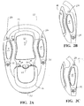
- FIGS. 2A-2C are enlarged plan views of the footswitch of the present invention illustrating the adjustability of the side switches.
- FIG. 3 is an exploded perspective view of the surgical footswitch illustrating the assembly of the side switches.
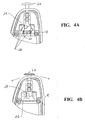
- FIGS. 4A-4B are bottom plan views of the side switches that may be used with the footswitch of the present invention illustrating the operation of the rotational locking mechanism.
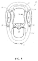
- FIG. 5 is a top plan view of the footswitch of the present invention.
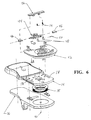
- FIG. 6 is an exploded assembly drawing of the heel cup slide adjustment mechanism that may be used with the footswitch of the present invention.
- FIGS. 7A-7B are top plan views of the heel cup that may be used with the footswitch of the present invention illustrating the operation of the slidable heel cup adjustment mechanism.
- FIG. 8 is a top plan view of the footswitch of the present invention similar to FIG. 6, but illustrating the rotational operation of the treadle.
- FIGS. 9A-9B are bottom plan views of the treadle switches that may be used with the footswitch of the present invention.
- FIG. 10 is a side partial cross-sectional view of the footswitch of the present invention illustrating the location of the treadle pivot point with respect to the ankle of the user.
- FIGS. 11A-11B are side plan view of the footswitch of the present invention illustrating the operation of the treadle rotation lock.
- FIG. 12 is a top plan view of the footswitch of the present invention similar to FIGS. 6 and 8, but illustrating the rotational operation of the heel cup.
- FIG. 13 is an exploded assembly drawing of the heel cup rotation mechanism.
- FIG. 14 is a bottom plan view of the footswitch of the present invention.
- FIGS. 15A-15C are cross-sectional view of the footswitch of the present invention illustrating the operation of the anti-gravity spring plunger feet.
- As best seen in FIG. 1,
footswitch 10 of the present invention generally includesbase 12,treadle 14 havingheel cup 16 and side orwing switches 18, all of which can be made from any suitable material, such as stainless steel, titanium or plastic.Base 12 may containprotective bumper 20 made from a relatively soft elastomeric material. As best seen in FIGS. 2A-2C, 3 and 4A-4B,side switches 18 may be adjusted inwardly (FIG. 2B) or outwardly (FIG. 2C) to increase or decrease the distance betweenswitches 18 and accommodate for variations in the width ofuser foot 100. Such adjustment is accomplished by pushing onlocking buttons 22, causinglocking pin 24 onbase 12 to be released from withindetents 26 inswitches 18 and rotating aboutpins 28 inholes 30 located onbase 12. Whenbuttons 22 are released, springs 32push detents 26 against lockingpin 24, thereby holdingswitches 18 in a locked position. The relative position ofswitches 18 may be determined visually by the use ofswitch position indicators 34, as best seen in FIGS. 2B and 2C. - As best seen in FIGS. 5, 6 and 7A-7B, the length of
treadle 14 may be adjusted by sliding movement ofheel cup 16. As best seen in FIG. 6,treadle 14 is mounted totreadle base 36 by thrust bearing 38, thereby allowingtreadle 14 to pivot aboutaxis 40.Heel cup slide 42 is received ontreadle 14 and containslocking lever 44, which is held ontoheel cup slide 42 byretainers 46.Locking pins 48 are held withinlocking lever 44 byshafts 50.Locking pins 48 are biased into lockingpin holes 52 intreadle 14 bysprings 54 pushing against lockingpin retainer 56. In this manner, pushing onlocking lever 44pulls locking pins 48 out oflocking pin holes 52 and allowsheel cup slide 42 to slide lengthwise alongslots 58 intreadle 14 as illustrated in FIGS. 7A-7B. The relative position ofheel cup 16 relative totreadle 14 may be visually indicated byindicators 60. In addition,treadle 14 may containraised reference point 62, indicating the center oftreadle 14. - The width and length adjustments described above preferably allow
footswitch 10 to be adjusted to accommodate the 5th percentile female to the 95th percentile male foot width and length, with or without shoes. As best seen in FIG. 10,ankle rotation axis 65 offoot 100 is located behindpivot axis 68 oftreadle 14 for all three treadle lengths. - As best seen in FIGS. 8 and 9A-9B,
treadle 14 may rotate or counter-rotate about thrust bearing 38 to operate left andright switches 64, which are mounted ontreadle base 36.Return springs 66 provide for automatic centering oftreadle 14 following rotation. As best seen in FIGS. 11A and 11B,treadle base 36 containsalignment pin 70 that fits withinhole 72 inbase 12 whentreadle 14 is in the resting, non-pivoted position. Such a construction prevent rotation oftreadle 14 toactivation switches 64 when treadle is in the resting, non-pivoted position (FIG. 11A), but allows rotation oftreadle 14 whentreadle 14 is depressed or pivoted (FIG. 11B). - As shown in FIGS. 12 and 13,
heel cup 16 is mounted toheel cup slide 42 usingthrust bearing 74,alignment cap 76 and screws 82. Such a construction allow for the rotation ofheel cup 16 independently of any rotation of treadle 14 (as show in FIGS 8 and 9A-9B) and allows for the operation of side switches 18 when treadle is in the resting and rotationally locked position (FIG. 11A). Return lever, 78, mounted toheel cup 16 acts against return springs 80 to provide for automatic centering ofheel cup 16 in the resting position. - As shown in FIGS. 14 and 15A-15C, bottom 85 of
base 12 preferably is covered by relatively high friction polymer (e.g., VERSAFLEX TPE)material 84 and contains a plurality of retractable, anti-gravity spring-loadedplunger feet 86 made from a low friction polymer material (e.g., DELRIN® acetal resin). As shown in FIG. 15A and 15B, when there is no weight onfootswitch 10, spring loadedplunger 86 project a short distance D (e.g., 0.04 inches) outwardly from bottom 84, thereby contacting the floor and allowing easy sliding offootswitch 10 on relatively low friction plunger tips 88. As shown in FIG. 15C, when weight is placed onfootswitch 10,plungers 86 retract, and high friction bottom 84 contacts the floor, thereby making it more difficult to slidefootswitch 10 during use. - Although it is not intended to limit the present invention to any one set of parameters or relationships, typically the plungers are provided from a material having a coefficient of friction of 0.3 or less vs. a standard Vinyl tile floor and the overmold is formed from an elastomer material having a coefficient of friction of 1.0 or greater. The overmold typically has a coefficient of friction of 5 times or more of the plungers. In one exemplary non-limiting embodiment the coefficient of friction for the Delrin™ plunger is 0.12 and the coefficient of friction for the bottom overmold is 1.59.
- This description is given for purposes of illustration and explanation. It will be apparent to those skilled in the relevant art that modifications may be made to the invention as herein described without departing from its scope.
Claims (9)
- A surgical footswitch, comprising:a) a base (12);b) a treadle (14) mounted to the base; andc) a heel cup;characterised in that the heel cup (16) is slidably retained on the treadle so as to adjustably increase or decrease a length of the treadle and wherein the heel cup may be rotated independently of any movement of the treadle.
- The footswitch of claim 1 wherein the heel cup is prevented from sliding by a plurality of locking pins (48) mounted on the heel cup, the locking pins fitting within locking holes (52) in the treadle.
- The footswitch of claims 1 or 2 wherein the position of the heel cup is visually indicated by position indicators (60).
- The footswitch of any preceding claim wherein the treadle contains a raised reference point (62) for assisting in centering a foot on the treadle.
- The footswitch of claim 3 wherein the switches or heel cup may be slidable adjusted to accommodate the 5th percentile female to the 95th percentile male foot length, with or without shoes.
- The footswitch of any preceding claim wherein the treadle (14) is pivotally and rotationally mounted to the base; and the switch further includes:a) a pair of switches (64) mounted to the treadle so that rotation or counter-rotation of the treadle operates the switches.
- The footswitch of claim 6 further comprising a locking pin (70) mounted on the treadle that fits within a locking hole (72) in the base (12) so as to prevent rotation of the treadle and operation of the switches when the treadle is in a resting, non-pivoted position.
- The footswitch of claim 1 further comprising a pair of side switches rotationally mounted to the base on either side of the treadle, so that rotation of the heel cup allows operation of the switches independently of any movement of the treadle.
- The footswitch of claim 1 wherein the treadle is mounted to the base so as to be pivotal about a pivot axis; and the heel cup is slidably retained on the treadle so as to adjustably increase or decrease a length of the treadle while maintaining the pivot axis slightly ahead of an ankle rotation axis of a foot of a user.
Applications Claiming Priority (6)
| Application Number | Priority Date | Filing Date | Title |
|---|---|---|---|
| US166339 | 2002-08-26 | ||
| US29/166,339 USD478323S1 (en) | 2002-08-26 | 2002-08-26 | Footswitch |
| US40821102P | 2002-09-04 | 2002-09-04 | |
| US408211P | 2002-09-04 | ||
| US271505 | 2002-10-16 | ||
| US10/271,505 US6862951B2 (en) | 2002-08-26 | 2002-10-16 | Footswitch |
Related Parent Applications (1)
| Application Number | Title | Priority Date | Filing Date |
|---|---|---|---|
| EP03077566A Division EP1394828B1 (en) | 2002-08-26 | 2003-08-15 | Footswitch |
Publications (2)
| Publication Number | Publication Date |
|---|---|
| EP1521279A1 EP1521279A1 (en) | 2005-04-06 |
| EP1521279B1 true EP1521279B1 (en) | 2006-11-02 |
Family
ID=34198841
Family Applications (4)
| Application Number | Title | Priority Date | Filing Date |
|---|---|---|---|
| EP04105968A Expired - Lifetime EP1521278B1 (en) | 2002-08-26 | 2003-08-15 | Footswitch |
| EP04105969A Expired - Lifetime EP1553608B1 (en) | 2002-08-26 | 2003-08-15 | Footswitch |
| EP03077566A Expired - Lifetime EP1394828B1 (en) | 2002-08-26 | 2003-08-15 | Footswitch |
| EP04105971A Expired - Lifetime EP1521279B1 (en) | 2002-08-26 | 2003-08-15 | Footswitch |
Family Applications Before (3)
| Application Number | Title | Priority Date | Filing Date |
|---|---|---|---|
| EP04105968A Expired - Lifetime EP1521278B1 (en) | 2002-08-26 | 2003-08-15 | Footswitch |
| EP04105969A Expired - Lifetime EP1553608B1 (en) | 2002-08-26 | 2003-08-15 | Footswitch |
| EP03077566A Expired - Lifetime EP1394828B1 (en) | 2002-08-26 | 2003-08-15 | Footswitch |
Country Status (6)
| Country | Link |
|---|---|
| US (2) | US6862951B2 (en) |
| EP (4) | EP1521278B1 (en) |
| AT (4) | ATE348395T1 (en) |
| DE (4) | DE60309475T2 (en) |
| DK (4) | DK1521279T3 (en) |
| ES (4) | ES2276232T3 (en) |
Families Citing this family (74)
| Publication number | Priority date | Publication date | Assignee | Title |
|---|---|---|---|---|
| WO2004073751A2 (en) * | 2003-02-14 | 2004-09-02 | Alcon, Inc. | Apparatus and method for determining that a surgical fluid container is near empty |
| WO2004073546A2 (en) * | 2003-02-14 | 2004-09-02 | Alcon, Inc., | Apparatus and method for determining that a surgical fluid container is near empty |
| US7019234B1 (en) * | 2003-11-13 | 2006-03-28 | Alcon, Inc. | Footswitch |
| US7084364B2 (en) * | 2003-11-13 | 2006-08-01 | Alcon, Inc. | Dual control footswitch assembly |
| US20060145540A1 (en) * | 2004-11-12 | 2006-07-06 | Mezhinsky Victor B | Dual linear control footswitch |
| CA2803828C (en) * | 2005-03-31 | 2015-11-24 | Alcon, Inc. | Footswitch operable to control a surgical system |
| USD540227S1 (en) | 2005-05-17 | 2007-04-10 | Teleflex Incorporated | Foot pedal |
| US7626132B2 (en) * | 2005-10-13 | 2009-12-01 | Alcon, Inc. | Foot controller |
| US8380126B1 (en) | 2005-10-13 | 2013-02-19 | Abbott Medical Optics Inc. | Reliable communications for wireless devices |
| US8565839B2 (en) * | 2005-10-13 | 2013-10-22 | Abbott Medical Optics Inc. | Power management for wireless devices |
| USD542740S1 (en) * | 2006-03-21 | 2007-05-15 | Linemaster Switch Corporation | Single foot pedal control |
| DE102006033054A1 (en) * | 2006-07-14 | 2008-01-17 | Carl Zeiss Surgical Gmbh | Ophthalmic surgical workstation |
| US7381917B2 (en) * | 2006-09-20 | 2008-06-03 | Alcon, Inc. | Footswitch assembly with position memory |
| US8414534B2 (en) | 2006-11-09 | 2013-04-09 | Abbott Medical Optics Inc. | Holding tank devices, systems, and methods for surgical fluidics cassette |
| US9522221B2 (en) | 2006-11-09 | 2016-12-20 | Abbott Medical Optics Inc. | Fluidics cassette for ocular surgical system |
| US8491528B2 (en) | 2006-11-09 | 2013-07-23 | Abbott Medical Optics Inc. | Critical alignment of fluidics cassettes |
| US10959881B2 (en) | 2006-11-09 | 2021-03-30 | Johnson & Johnson Surgical Vision, Inc. | Fluidics cassette for ocular surgical system |
| US9295765B2 (en) * | 2006-11-09 | 2016-03-29 | Abbott Medical Optics Inc. | Surgical fluidics cassette supporting multiple pumps |
| US7503124B2 (en) * | 2006-12-15 | 2009-03-17 | Black & Decker Inc. | Tool with non-slip feature or friction assembly |
| US8465473B2 (en) * | 2007-03-28 | 2013-06-18 | Novartis Ag | Surgical footswitch with movable shroud |
| US10596032B2 (en) * | 2007-05-24 | 2020-03-24 | Johnson & Johnson Surgical Vision, Inc. | System and method for controlling a transverse phacoemulsification system with a footpedal |
| US10363166B2 (en) | 2007-05-24 | 2019-07-30 | Johnson & Johnson Surgical Vision, Inc. | System and method for controlling a transverse phacoemulsification system using sensed data |
| US10485699B2 (en) | 2007-05-24 | 2019-11-26 | Johnson & Johnson Surgical Vision, Inc. | Systems and methods for transverse phacoemulsification |
| US20090005789A1 (en) * | 2007-06-26 | 2009-01-01 | Charles Steven T | Force Sensitive Foot Controller |
| US10342701B2 (en) * | 2007-08-13 | 2019-07-09 | Johnson & Johnson Surgical Vision, Inc. | Systems and methods for phacoemulsification with vacuum based pumps |
| US20090307681A1 (en) * | 2008-06-05 | 2009-12-10 | Ryan Armado | Wireless Network and Methods of Wireless Communication For Ophthalmic Surgical Consoles |
| CA2742977C (en) | 2008-11-07 | 2017-01-24 | Abbott Medical Optics Inc. | Adjustable foot pedal control for ophthalmic surgery |
| US10219940B2 (en) | 2008-11-07 | 2019-03-05 | Johnson & Johnson Surgical Vision, Inc. | Automatically pulsing different aspiration levels to an ocular probe |
| US9566188B2 (en) | 2008-11-07 | 2017-02-14 | Abbott Medical Optics Inc. | Automatically switching different aspiration levels and/or pumps to an ocular probe |
| EP2341878B1 (en) * | 2008-11-07 | 2017-06-21 | Abbott Medical Optics Inc. | Semi-automatic device calibraton |
| US9795507B2 (en) | 2008-11-07 | 2017-10-24 | Abbott Medical Optics Inc. | Multifunction foot pedal |
| AU2015203096B2 (en) * | 2008-11-07 | 2016-09-08 | Johnson & Johnson Surgical Vision, Inc. | Adjustable foot pedal control for ophthalmic surgery |
| AU2009313417B2 (en) * | 2008-11-07 | 2015-01-15 | Johnson & Johnson Surgical Vision, Inc. | Method for programming foot pedal settings and controlling performance through foot pedal variation |
| WO2010054142A1 (en) | 2008-11-07 | 2010-05-14 | Abbott Medical Optics Inc. | Controlling of multiple pumps |
| AU2009313416B2 (en) | 2008-11-07 | 2015-03-26 | Johnson & Johnson Surgical Vision, Inc. | Surgical cassette apparatus |
| USD623209S1 (en) * | 2008-11-12 | 2010-09-07 | Carl Zeiss Surgical Gmbh | Foot switch console for use with a surgical microscope |
| US9492317B2 (en) * | 2009-03-31 | 2016-11-15 | Abbott Medical Optics Inc. | Cassette capture mechanism |
| NO329473B1 (en) * | 2009-04-01 | 2010-10-25 | Trenmentor Jan Wiese | Foot operated control device |
| US8623040B2 (en) | 2009-07-01 | 2014-01-07 | Alcon Research, Ltd. | Phacoemulsification hook tip |
| CN102129921A (en) * | 2010-01-13 | 2011-07-20 | 张世宗 | foot switch |
| US10226167B2 (en) | 2010-05-13 | 2019-03-12 | Beaver-Visitec International, Inc. | Laser video endoscope |
| US20160095507A1 (en) | 2010-05-13 | 2016-04-07 | Beaver-Visitec International, Inc. | Laser video endoscope |
| US10258505B2 (en) | 2010-09-17 | 2019-04-16 | Alcon Research, Ltd. | Balanced phacoemulsification tip |
| GB201020505D0 (en) * | 2010-12-03 | 2011-01-19 | Valtra Oy Ab | Adjustable pedal |
| US9240110B2 (en) | 2011-10-20 | 2016-01-19 | Alcon Research, Ltd. | Haptic footswitch treadle |
| WO2013142009A1 (en) | 2012-03-17 | 2013-09-26 | Abbott Medical Optics, Inc. | Surgical cassette |
| US10828193B2 (en) * | 2013-04-19 | 2020-11-10 | Johnson & Johnson Surgical Vision, Inc. | Foot pedal system and apparatus |
| USD708593S1 (en) * | 2013-04-19 | 2014-07-08 | Abbott Medical Optics Inc. | Foot pedal |
| KR101529971B1 (en) * | 2014-01-27 | 2015-06-26 | 주식회사 로보쓰리 | The backpack type a self balancing scooter with a steering mechanism using foot |
| US9778675B2 (en) * | 2014-02-17 | 2017-10-03 | Ormco Corporation | Foot pedal for a medical device having a self-leveling mechanism |
| USD813760S1 (en) * | 2014-12-22 | 2018-03-27 | Johnson Technologies Corporation | Ergonomic pedal |
| KR101698465B1 (en) * | 2015-02-25 | 2017-01-20 | 하이윈 테크놀로지스 코포레이션 | Multidirectional foot controller |
| US10195317B2 (en) * | 2015-11-12 | 2019-02-05 | Johnson & Johnson Surgical Vision, Inc. | Foot pedal occlusion indicator system, apparatus, and method |
| CN105476781B (en) * | 2016-01-08 | 2017-09-15 | 深圳市美格尔医疗设备股份有限公司 | A kind of telescopic pedal switch of bed body |
| KR101800679B1 (en) * | 2016-01-14 | 2017-11-23 | 주식회사 로보쓰리 | The handsfree balancing scooter with a steering mechanism of twist type using feet |
| DE102016105554B4 (en) | 2016-03-24 | 2019-03-28 | Carl Zeiss Meditec Ag | Foot control device for operating a surgical device, surgical device and method for operating a foot control device |
| WO2018092006A2 (en) | 2016-11-17 | 2018-05-24 | Novartis Ag | Tri-axial ergonomic footswitch |
| US10736700B2 (en) | 2016-11-17 | 2020-08-11 | Alcon Inc. | Ergonomic foot-operated system |
| CN110636811A (en) * | 2017-05-24 | 2019-12-31 | 柯惠Lp公司 | Pedal Control for Robotic Surgical Systems |
| DE202018100723U1 (en) * | 2018-02-09 | 2019-05-14 | Steute Technologies Gmbh & Co. Kg | footswitch |
| USD867307S1 (en) * | 2018-03-20 | 2019-11-19 | Conntrol International, Inc. | Foot switch |
| US10901450B2 (en) | 2018-08-21 | 2021-01-26 | Alcon Inc. | Multi-functional surgical foot controller with integrated shroud |
| US10925680B2 (en) | 2018-09-18 | 2021-02-23 | Alcon Inc. | Foot controller with adjustable treadle |
| DE102018133504A1 (en) | 2018-12-21 | 2020-06-25 | Aesculap Ag | Integrated power unit IPU |
| DE102019101308A1 (en) | 2019-01-18 | 2020-07-23 | Aesculap Ag | Integrated power unit IPU |
| USD905757S1 (en) * | 2019-06-20 | 2020-12-22 | Garmin Switzerland Gmbh | Foot pedal |
| NL2023465B1 (en) * | 2019-07-09 | 2021-02-02 | Crea Ip B V | Foot switch assembly for controlling surgical instruments |
| US11740648B2 (en) * | 2019-08-01 | 2023-08-29 | Alcon Inc. | Surgical footswitch having elevated auxiliary buttons |
| USD911982S1 (en) * | 2019-10-10 | 2021-03-02 | Johnson & Johnson Surgical Vision, Inc. | Foot pedal |
| US12256910B2 (en) * | 2020-06-11 | 2025-03-25 | Johnson & Johnson Surgical Vision, Inc. | System and apparatus for enhancing the ergonomics of a surgical foot pedal |
| NL2026343B1 (en) * | 2020-08-26 | 2022-04-29 | Future Cleaning Tech B V | Foot operable assembly |
| US11845178B2 (en) | 2020-11-03 | 2023-12-19 | Techtronic Cordless Gp | Modular work station |
| CN114833849B (en) * | 2022-06-06 | 2024-01-16 | 深圳市尚为照明有限公司 | Explosion-proof robot |
| USD1117112S1 (en) * | 2024-03-15 | 2026-03-10 | Navico Group Americas, LLC | Marine detachable control module |
Family Cites Families (46)
| Publication number | Priority date | Publication date | Assignee | Title |
|---|---|---|---|---|
| US115917A (en) * | 1871-06-13 | Improvement in hose-couplings | ||
| GB1051785A (en) * | 1900-01-01 | |||
| US1051785A (en) * | 1912-04-10 | 1913-01-28 | Franz Trinks | Calculating-machine. |
| ES311348A2 (en) | 1965-04-02 | 1965-07-16 | Frontera Pascual Antonio | A combined accelerator and brake pedal |
| US3761598A (en) * | 1971-08-03 | 1973-09-25 | E Haile | Foot-operated chord xylophone |
| US3789836A (en) * | 1972-12-07 | 1974-02-05 | Scott J | Apparatus for the stimulation of blood circulation in feet and legs |
| US3841172A (en) * | 1973-11-08 | 1974-10-15 | Ware Machine Works Inc | Foot pedal valve control for earth-moving equipment |
| DE2916081C2 (en) * | 1979-04-20 | 1982-07-01 | Kaltenbach & Voigt Gmbh & Co, 7950 Biberach | Circuit arrangement for controlling the drive of dental treatment instruments |
| US4267414A (en) | 1979-08-02 | 1981-05-12 | Michael B. Brueggeman | Foot control for snow plows |
| US4337939A (en) * | 1980-02-20 | 1982-07-06 | Hoyle David C | Ankle exercise device |
| US4837857A (en) | 1986-11-06 | 1989-06-06 | Storz Instrument Company | Foot pedal assembly for ophthalmic surgical instrument |
| US4759734A (en) * | 1986-12-23 | 1988-07-26 | Robert S. Scheurer | Water ski binder |
| CH672976A5 (en) | 1987-09-18 | 1990-01-31 | Raichle Sportschuh Ag | |
| DE3903401A1 (en) | 1989-02-05 | 1990-08-09 | Joerg Marris | Binding set for a snowboard, and arrangement of a binding set on a snowboard |
| US4965417A (en) | 1989-03-27 | 1990-10-23 | Massie Philip E | Foot-operated control |
| US4983901A (en) | 1989-04-21 | 1991-01-08 | Allergan, Inc. | Digital electronic foot control for medical apparatus and the like |
| US5091656A (en) | 1989-10-27 | 1992-02-25 | Storz Instrument Company | Footswitch assembly with electrically engaged detents |
| US5094226A (en) * | 1990-10-31 | 1992-03-10 | Mark T. Medcalf | Continuous passive motion device for the first metatarsal phalangeal joint |
| WO1993002627A1 (en) | 1991-07-31 | 1993-02-18 | Mentor O&O Inc. | Controlling operation of handpieces during ophthalmic surgery |
| NO172974C (en) * | 1991-08-16 | 1993-10-06 | Rune Angeltun | BICYCLE PEDAL |
| US5268624A (en) | 1992-10-14 | 1993-12-07 | Allergan, Inc. | Foot pedal control with user-selectable operational ranges |
| US5422521A (en) * | 1993-11-18 | 1995-06-06 | Liebel-Flarsheim Co. | Foot operated control system for a multi-function device |
| US5787760A (en) | 1993-11-24 | 1998-08-04 | Thorlakson; Richard G. | Method and foot pedal apparatus for operating a microscope |
| US5554894A (en) | 1994-10-28 | 1996-09-10 | Iolab Corporation | Electronic footswitch for ophthalmic surgery |
| US5635777A (en) | 1995-12-28 | 1997-06-03 | Andrew Telymonde | Foot operated control apparatus |
| US5990400A (en) * | 1996-02-22 | 1999-11-23 | Hoshino Gakki Kabushiki Kaisha | Connection between the pedal and heel plates of a foot pedal |
| US6010496A (en) | 1996-08-29 | 2000-01-04 | Bausch & Lomb Surgical, Inc. | Vitrectomy timing device with microcontroller with programmable timers |
| JP4094063B2 (en) | 1996-08-29 | 2008-06-04 | ボシュロム インコーポレイテッド | Dual loop control of frequency and power |
| US6786502B2 (en) * | 1997-07-28 | 2004-09-07 | Stephen R. Carlson | Longitudinally adjustable mount for a snowboard binding |
| US6179829B1 (en) | 1997-08-28 | 2001-01-30 | Bausch & Lomb Surgical, Inc. | Foot controller for microsurgical system |
| US5983749A (en) | 1997-09-12 | 1999-11-16 | Allergan Sales, Inc. | Dual position foot pedal for ophthalmic surgery apparatus |
| US6150623A (en) | 1998-08-27 | 2000-11-21 | Allergan | Back-flip medical footpedal |
| DE19855552A1 (en) * | 1998-12-02 | 2000-06-08 | Martin Stobbe | Foot operated controller for computer cursor has foot-operated switches arranged side by side in stepped formation |
| JP2000229102A (en) | 1999-02-09 | 2000-08-22 | Nidek Co Ltd | Foot switch for ophthalmologic surgery and ophthalmologic surgical instrument equipped with the same |
| US6452120B1 (en) | 2000-05-11 | 2002-09-17 | Advanced Medical Optics | Dual dimensional shoe sensor and foot pedal operated switch for surgical control |
| US6452123B1 (en) | 2000-06-27 | 2002-09-17 | Advanced Medical Optics | Surgical foot pedal control including ribbon switch arrangement |
| ES2218455T3 (en) | 2000-10-17 | 2004-11-16 | Alcon Inc. | SUSTAINABLE GRAPHIC REPRESENTATION FOOT CONTROLLER FOR A MICRO-SURGICAL SYSTEM. |
| US6742286B2 (en) * | 2001-01-23 | 2004-06-01 | Kahtoola, Inc. | Flexible traction system for common shoes |
| JP2002238919A (en) * | 2001-02-20 | 2002-08-27 | Olympus Optical Co Ltd | Control apparatus for medical care system and medical care system |
| US7012203B2 (en) | 2001-09-07 | 2006-03-14 | Carl Zeiss Surgical Gmbh | Foot switch pedal controller for a surgical instrument |
| US6674030B2 (en) | 2001-09-19 | 2004-01-06 | Advanced Medical Optics | Intelligent surgical footpedal with low noise, low resistance vibration feedback |
| US6689975B2 (en) | 2001-12-19 | 2004-02-10 | Bausch & Lomb Incorporated | Foot controller including multiple switch arrangement with heel operated, door-type switch actuator |
| US6639332B2 (en) | 2001-12-19 | 2003-10-28 | Bausch & Lomb Incorporated | Foot controller with ophthalmic surgery interlock circuit and method |
| US6886427B2 (en) * | 2002-05-17 | 2005-05-03 | Logitech Europe S.A. | Floor lock for foot-operated device |
| US7019234B1 (en) * | 2003-11-13 | 2006-03-28 | Alcon, Inc. | Footswitch |
| US20060145540A1 (en) * | 2004-11-12 | 2006-07-06 | Mezhinsky Victor B | Dual linear control footswitch |
-
2002
- 2002-10-16 US US10/271,505 patent/US6862951B2/en not_active Expired - Lifetime
-
2003
- 2003-08-15 AT AT04105968T patent/ATE348395T1/en active
- 2003-08-15 ES ES04105969T patent/ES2276232T3/en not_active Expired - Lifetime
- 2003-08-15 DE DE60309475T patent/DE60309475T2/en not_active Expired - Lifetime
- 2003-08-15 DK DK04105971T patent/DK1521279T3/en active
- 2003-08-15 AT AT04105969T patent/ATE347170T1/en active
- 2003-08-15 DE DE60310405T patent/DE60310405T2/en not_active Expired - Lifetime
- 2003-08-15 EP EP04105968A patent/EP1521278B1/en not_active Expired - Lifetime
- 2003-08-15 ES ES04105971T patent/ES2275182T3/en not_active Expired - Lifetime
- 2003-08-15 DK DK04105968T patent/DK1521278T3/en active
- 2003-08-15 EP EP04105969A patent/EP1553608B1/en not_active Expired - Lifetime
- 2003-08-15 DK DK03077566T patent/DK1394828T3/en active
- 2003-08-15 EP EP03077566A patent/EP1394828B1/en not_active Expired - Lifetime
- 2003-08-15 DE DE60300237T patent/DE60300237T2/en not_active Expired - Lifetime
- 2003-08-15 AT AT04105971T patent/ATE344527T1/en active
- 2003-08-15 ES ES04105968T patent/ES2276231T3/en not_active Expired - Lifetime
- 2003-08-15 AT AT03077566T patent/ATE285622T1/en active
- 2003-08-15 EP EP04105971A patent/EP1521279B1/en not_active Expired - Lifetime
- 2003-08-15 ES ES03077566T patent/ES2235142T3/en not_active Expired - Lifetime
- 2003-08-15 DE DE60310115T patent/DE60310115T2/en not_active Expired - Lifetime
- 2003-08-15 DK DK04105969T patent/DK1553608T3/en active
-
2004
- 2004-09-29 US US10/953,624 patent/US7185555B2/en not_active Expired - Lifetime
Also Published As
| Publication number | Publication date |
|---|---|
| DE60310405T2 (en) | 2007-10-31 |
| EP1521278B1 (en) | 2006-12-13 |
| DK1521278T3 (en) | 2007-04-16 |
| ES2276232T3 (en) | 2007-06-16 |
| ATE347170T1 (en) | 2006-12-15 |
| EP1521278A1 (en) | 2005-04-06 |
| DE60309475D1 (en) | 2006-12-14 |
| EP1553608A3 (en) | 2005-07-20 |
| DK1521279T3 (en) | 2007-02-26 |
| DK1394828T3 (en) | 2005-04-25 |
| ES2235142T3 (en) | 2005-07-01 |
| ES2275182T3 (en) | 2007-06-01 |
| DE60300237D1 (en) | 2005-01-27 |
| EP1394828A1 (en) | 2004-03-03 |
| DE60310405D1 (en) | 2007-01-25 |
| US20050039567A1 (en) | 2005-02-24 |
| EP1553608A2 (en) | 2005-07-13 |
| DE60300237T2 (en) | 2005-12-15 |
| US6862951B2 (en) | 2005-03-08 |
| EP1394828B1 (en) | 2004-12-22 |
| EP1553608B1 (en) | 2006-11-29 |
| ATE348395T1 (en) | 2007-01-15 |
| US7185555B2 (en) | 2007-03-06 |
| US20040035242A1 (en) | 2004-02-26 |
| ES2276231T3 (en) | 2007-06-16 |
| EP1521279A1 (en) | 2005-04-06 |
| DE60310115T2 (en) | 2007-06-06 |
| ATE344527T1 (en) | 2006-11-15 |
| DE60310115D1 (en) | 2007-01-11 |
| DE60309475T2 (en) | 2007-08-16 |
| DK1553608T3 (en) | 2007-04-02 |
| ATE285622T1 (en) | 2005-01-15 |
Similar Documents
| Publication | Publication Date | Title |
|---|---|---|
| EP1521279B1 (en) | Footswitch | |
| JP5314095B2 (en) | Surgical footswitch | |
| CA2951889C (en) | Adjustable foot pedal control for ophthalmic surgery | |
| EP1012686B1 (en) | Dual position foot pedal for ophthalmic surgery apparatus | |
| CN1490832B (en) | Pedal switch | |
| PT1521278E (en) | Footswitch |
Legal Events
| Date | Code | Title | Description |
|---|---|---|---|
| PUAI | Public reference made under article 153(3) epc to a published international application that has entered the european phase |
Free format text: ORIGINAL CODE: 0009012 |
|
| 17P | Request for examination filed |
Effective date: 20041122 |
|
| AC | Divisional application: reference to earlier application |
Ref document number: 1394828 Country of ref document: EP Kind code of ref document: P |
|
| AK | Designated contracting states |
Kind code of ref document: A1 Designated state(s): AT BE BG CH CY CZ DE DK EE ES FI FR GB GR HU IE IT LI LU MC NL PT RO SE SI SK TR |
|
| AX | Request for extension of the european patent |
Extension state: AL LT LV MK |
|
| AKX | Designation fees paid |
Designated state(s): AT BE BG CH CY CZ DE DK EE ES FI FR GB GR HU IE IT LI LU MC NL PT RO SE SI SK TR |
|
| RAP1 | Party data changed (applicant data changed or rights of an application transferred) |
Owner name: ALCON, INC. |
|
| GRAP | Despatch of communication of intention to grant a patent |
Free format text: ORIGINAL CODE: EPIDOSNIGR1 |
|
| GRAS | Grant fee paid |
Free format text: ORIGINAL CODE: EPIDOSNIGR3 |
|
| GRAA | (expected) grant |
Free format text: ORIGINAL CODE: 0009210 |
|
| AC | Divisional application: reference to earlier application |
Ref document number: 1394828 Country of ref document: EP Kind code of ref document: P |
|
| AK | Designated contracting states |
Kind code of ref document: B1 Designated state(s): AT BE BG CH CY CZ DE DK EE ES FI FR GB GR HU IE IT LI LU MC NL PT RO SE SI SK TR |
|
| PG25 | Lapsed in a contracting state [announced via postgrant information from national office to epo] |
Ref country code: SK Free format text: LAPSE BECAUSE OF FAILURE TO SUBMIT A TRANSLATION OF THE DESCRIPTION OR TO PAY THE FEE WITHIN THE PRESCRIBED TIME-LIMIT Effective date: 20061102 Ref country code: RO Free format text: LAPSE BECAUSE OF FAILURE TO SUBMIT A TRANSLATION OF THE DESCRIPTION OR TO PAY THE FEE WITHIN THE PRESCRIBED TIME-LIMIT Effective date: 20061102 Ref country code: SI Free format text: LAPSE BECAUSE OF FAILURE TO SUBMIT A TRANSLATION OF THE DESCRIPTION OR TO PAY THE FEE WITHIN THE PRESCRIBED TIME-LIMIT Effective date: 20061102 Ref country code: CZ Free format text: LAPSE BECAUSE OF FAILURE TO SUBMIT A TRANSLATION OF THE DESCRIPTION OR TO PAY THE FEE WITHIN THE PRESCRIBED TIME-LIMIT Effective date: 20061102 |
|
| REG | Reference to a national code |
Ref country code: GB Ref legal event code: FG4D |
|
| REG | Reference to a national code |
Ref country code: IE Ref legal event code: FG4D |
|
| REG | Reference to a national code |
Ref country code: CH Ref legal event code: EP |
|
| REF | Corresponds to: |
Ref document number: 60309475 Country of ref document: DE Date of ref document: 20061214 Kind code of ref document: P |
|
| PG25 | Lapsed in a contracting state [announced via postgrant information from national office to epo] |
Ref country code: BG Free format text: LAPSE BECAUSE OF FAILURE TO SUBMIT A TRANSLATION OF THE DESCRIPTION OR TO PAY THE FEE WITHIN THE PRESCRIBED TIME-LIMIT Effective date: 20070202 |
|
| REG | Reference to a national code |
Ref country code: SE Ref legal event code: TRGR |
|
| REG | Reference to a national code |
Ref country code: DK Ref legal event code: T3 |
|
| REG | Reference to a national code |
Ref country code: CH Ref legal event code: NV Representative=s name: CRONIN INTELLECTUAL PROPERTY |
|
| PG25 | Lapsed in a contracting state [announced via postgrant information from national office to epo] |
Ref country code: PT Free format text: LAPSE BECAUSE OF FAILURE TO SUBMIT A TRANSLATION OF THE DESCRIPTION OR TO PAY THE FEE WITHIN THE PRESCRIBED TIME-LIMIT Effective date: 20070402 |
|
| REG | Reference to a national code |
Ref country code: CH Ref legal event code: PCAR Free format text: CRONIN INTELLECTUAL PROPERTY;CHEMIN DE PRECOSSY 31;1260 NYON (CH) |
|
| REG | Reference to a national code |
Ref country code: ES Ref legal event code: FG2A Ref document number: 2275182 Country of ref document: ES Kind code of ref document: T3 |
|
| ET | Fr: translation filed | ||
| PLBE | No opposition filed within time limit |
Free format text: ORIGINAL CODE: 0009261 |
|
| STAA | Information on the status of an ep patent application or granted ep patent |
Free format text: STATUS: NO OPPOSITION FILED WITHIN TIME LIMIT |
|
| 26N | No opposition filed |
Effective date: 20070803 |
|
| PG25 | Lapsed in a contracting state [announced via postgrant information from national office to epo] |
Ref country code: GR Free format text: LAPSE BECAUSE OF FAILURE TO SUBMIT A TRANSLATION OF THE DESCRIPTION OR TO PAY THE FEE WITHIN THE PRESCRIBED TIME-LIMIT Effective date: 20070203 |
|
| PG25 | Lapsed in a contracting state [announced via postgrant information from national office to epo] |
Ref country code: EE Free format text: LAPSE BECAUSE OF FAILURE TO SUBMIT A TRANSLATION OF THE DESCRIPTION OR TO PAY THE FEE WITHIN THE PRESCRIBED TIME-LIMIT Effective date: 20061102 |
|
| PG25 | Lapsed in a contracting state [announced via postgrant information from national office to epo] |
Ref country code: CY Free format text: LAPSE BECAUSE OF FAILURE TO SUBMIT A TRANSLATION OF THE DESCRIPTION OR TO PAY THE FEE WITHIN THE PRESCRIBED TIME-LIMIT Effective date: 20061102 |
|
| PG25 | Lapsed in a contracting state [announced via postgrant information from national office to epo] |
Ref country code: HU Free format text: LAPSE BECAUSE OF FAILURE TO SUBMIT A TRANSLATION OF THE DESCRIPTION OR TO PAY THE FEE WITHIN THE PRESCRIBED TIME-LIMIT Effective date: 20070503 Ref country code: TR Free format text: LAPSE BECAUSE OF FAILURE TO SUBMIT A TRANSLATION OF THE DESCRIPTION OR TO PAY THE FEE WITHIN THE PRESCRIBED TIME-LIMIT Effective date: 20061102 |
|
| PGFP | Annual fee paid to national office [announced via postgrant information from national office to epo] |
Ref country code: IE Payment date: 20110825 Year of fee payment: 9 Ref country code: MC Payment date: 20110720 Year of fee payment: 9 Ref country code: LU Payment date: 20110901 Year of fee payment: 9 Ref country code: DK Payment date: 20110826 Year of fee payment: 9 |
|
| PGFP | Annual fee paid to national office [announced via postgrant information from national office to epo] |
Ref country code: FI Payment date: 20110830 Year of fee payment: 9 Ref country code: SE Payment date: 20110829 Year of fee payment: 9 Ref country code: AT Payment date: 20110720 Year of fee payment: 9 |
|
| PGFP | Annual fee paid to national office [announced via postgrant information from national office to epo] |
Ref country code: BE Payment date: 20110825 Year of fee payment: 9 |
|
| BERE | Be: lapsed |
Owner name: ALCON, INC. Effective date: 20120831 |
|
| PG25 | Lapsed in a contracting state [announced via postgrant information from national office to epo] |
Ref country code: MC Free format text: LAPSE BECAUSE OF NON-PAYMENT OF DUE FEES Effective date: 20120831 |
|
| REG | Reference to a national code |
Ref country code: DK Ref legal event code: EBP Ref country code: SE Ref legal event code: EUG |
|
| REG | Reference to a national code |
Ref country code: AT Ref legal event code: MM01 Ref document number: 344527 Country of ref document: AT Kind code of ref document: T Effective date: 20120815 |
|
| PG25 | Lapsed in a contracting state [announced via postgrant information from national office to epo] |
Ref country code: FI Free format text: LAPSE BECAUSE OF NON-PAYMENT OF DUE FEES Effective date: 20120815 Ref country code: SE Free format text: LAPSE BECAUSE OF NON-PAYMENT OF DUE FEES Effective date: 20120816 |
|
| REG | Reference to a national code |
Ref country code: IE Ref legal event code: MM4A |
|
| PG25 | Lapsed in a contracting state [announced via postgrant information from national office to epo] |
Ref country code: BE Free format text: LAPSE BECAUSE OF NON-PAYMENT OF DUE FEES Effective date: 20120831 |
|
| PG25 | Lapsed in a contracting state [announced via postgrant information from national office to epo] |
Ref country code: AT Free format text: LAPSE BECAUSE OF NON-PAYMENT OF DUE FEES Effective date: 20120815 |
|
| PG25 | Lapsed in a contracting state [announced via postgrant information from national office to epo] |
Ref country code: IE Free format text: LAPSE BECAUSE OF NON-PAYMENT OF DUE FEES Effective date: 20120815 Ref country code: DK Free format text: LAPSE BECAUSE OF NON-PAYMENT OF DUE FEES Effective date: 20120831 |
|
| PG25 | Lapsed in a contracting state [announced via postgrant information from national office to epo] |
Ref country code: LU Free format text: LAPSE BECAUSE OF NON-PAYMENT OF DUE FEES Effective date: 20120815 |
|
| REG | Reference to a national code |
Ref country code: FR Ref legal event code: PLFP Year of fee payment: 14 |
|
| REG | Reference to a national code |
Ref country code: FR Ref legal event code: PLFP Year of fee payment: 15 |
|
| REG | Reference to a national code |
Ref country code: CH Ref legal event code: PCAR Free format text: NEW ADDRESS: CHEMIN DE LA VUARPILLIERE 29, 1260 NYON (CH) |
|
| REG | Reference to a national code |
Ref country code: FR Ref legal event code: PLFP Year of fee payment: 16 |
|
| PGFP | Annual fee paid to national office [announced via postgrant information from national office to epo] |
Ref country code: NL Payment date: 20190814 Year of fee payment: 17 |
|
| REG | Reference to a national code |
Ref country code: NL Ref legal event code: PD Owner name: ALCON INC.; CH Free format text: DETAILS ASSIGNMENT: CHANGE OF OWNER(S), MERGE; FORMER OWNER NAME: NOVARTIS AG Effective date: 20191031 |
|
| REG | Reference to a national code |
Ref country code: CH Ref legal event code: PUE Owner name: ALCON INC., CH Free format text: FORMER OWNER: ALCON, INC., CH |
|
| PGFP | Annual fee paid to national office [announced via postgrant information from national office to epo] |
Ref country code: CH Payment date: 20190819 Year of fee payment: 17 |
|
| REG | Reference to a national code |
Ref country code: GB Ref legal event code: 732E Free format text: REGISTERED BETWEEN 20200109 AND 20200115 |
|
| REG | Reference to a national code |
Ref country code: GB Ref legal event code: 732E Free format text: REGISTERED BETWEEN 20200116 AND 20200122 |
|
| REG | Reference to a national code |
Ref country code: DE Ref legal event code: R082 Ref document number: 60309475 Country of ref document: DE Representative=s name: BOEHMERT & BOEHMERT ANWALTSPARTNERSCHAFT MBB -, DE Ref country code: DE Ref legal event code: R081 Ref document number: 60309475 Country of ref document: DE Owner name: ALCON INC., CH Free format text: FORMER OWNER: ALCON INC., HUENENBERG, CH |
|
| REG | Reference to a national code |
Ref country code: ES Ref legal event code: PC2A Owner name: ALCON INC. Effective date: 20200430 |
|
| REG | Reference to a national code |
Ref country code: CH Ref legal event code: PL |
|
| REG | Reference to a national code |
Ref country code: NL Ref legal event code: MM Effective date: 20200901 |
|
| PG25 | Lapsed in a contracting state [announced via postgrant information from national office to epo] |
Ref country code: CH Free format text: LAPSE BECAUSE OF NON-PAYMENT OF DUE FEES Effective date: 20200831 Ref country code: LI Free format text: LAPSE BECAUSE OF NON-PAYMENT OF DUE FEES Effective date: 20200831 |
|
| PG25 | Lapsed in a contracting state [announced via postgrant information from national office to epo] |
Ref country code: NL Free format text: LAPSE BECAUSE OF NON-PAYMENT OF DUE FEES Effective date: 20200901 |
|
| PGFP | Annual fee paid to national office [announced via postgrant information from national office to epo] |
Ref country code: IT Payment date: 20220726 Year of fee payment: 20 Ref country code: GB Payment date: 20220721 Year of fee payment: 20 Ref country code: ES Payment date: 20220901 Year of fee payment: 20 Ref country code: DE Payment date: 20220608 Year of fee payment: 20 |
|
| PGFP | Annual fee paid to national office [announced via postgrant information from national office to epo] |
Ref country code: FR Payment date: 20220721 Year of fee payment: 20 |
|
| P01 | Opt-out of the competence of the unified patent court (upc) registered |
Effective date: 20230504 |
|
| REG | Reference to a national code |
Ref country code: DE Ref legal event code: R071 Ref document number: 60309475 Country of ref document: DE |
|
| REG | Reference to a national code |
Ref country code: ES Ref legal event code: FD2A Effective date: 20230825 |
|
| REG | Reference to a national code |
Ref country code: GB Ref legal event code: PE20 Expiry date: 20230814 |
|
| PG25 | Lapsed in a contracting state [announced via postgrant information from national office to epo] |
Ref country code: GB Free format text: LAPSE BECAUSE OF EXPIRATION OF PROTECTION Effective date: 20230814 Ref country code: ES Free format text: LAPSE BECAUSE OF EXPIRATION OF PROTECTION Effective date: 20230816 |