EP1521223A1 - Sensor monitor,monitor system, sensor monitor method, and program - Google Patents
Sensor monitor,monitor system, sensor monitor method, and program Download PDFInfo
- Publication number
- EP1521223A1 EP1521223A1 EP02745917A EP02745917A EP1521223A1 EP 1521223 A1 EP1521223 A1 EP 1521223A1 EP 02745917 A EP02745917 A EP 02745917A EP 02745917 A EP02745917 A EP 02745917A EP 1521223 A1 EP1521223 A1 EP 1521223A1
- Authority
- EP
- European Patent Office
- Prior art keywords
- notifying
- notification
- destination
- sensor
- unit
- Prior art date
- Legal status (The legal status is an assumption and is not a legal conclusion. Google has not performed a legal analysis and makes no representation as to the accuracy of the status listed.)
- Withdrawn
Links
Images

Classifications
-
- G—PHYSICS
- G08—SIGNALLING
- G08B—SIGNALLING SYSTEMS, e.g. PERSONAL CALLING SYSTEMS; ORDER TELEGRAPHS; ALARM SYSTEMS
- G08B25/00—Alarm systems in which the location of the alarm condition is signalled to a central station, e.g. fire or police telegraphic systems
- G08B25/01—Alarm systems in which the location of the alarm condition is signalled to a central station, e.g. fire or police telegraphic systems characterised by the transmission medium
- G08B25/014—Alarm signalling to a central station with two-way communication, e.g. with signalling back
-
- G—PHYSICS
- G08—SIGNALLING
- G08B—SIGNALLING SYSTEMS, e.g. PERSONAL CALLING SYSTEMS; ORDER TELEGRAPHS; ALARM SYSTEMS
- G08B25/00—Alarm systems in which the location of the alarm condition is signalled to a central station, e.g. fire or police telegraphic systems
- G08B25/001—Alarm cancelling procedures or alarm forwarding decisions, e.g. based on absence of alarm confirmation
-
- G—PHYSICS
- G08—SIGNALLING
- G08B—SIGNALLING SYSTEMS, e.g. PERSONAL CALLING SYSTEMS; ORDER TELEGRAPHS; ALARM SYSTEMS
- G08B25/00—Alarm systems in which the location of the alarm condition is signalled to a central station, e.g. fire or police telegraphic systems
- G08B25/006—Alarm destination chosen according to type of event, e.g. in case of fire phone the fire service, in case of medical emergency phone the ambulance
-
- G—PHYSICS
- G08—SIGNALLING
- G08B—SIGNALLING SYSTEMS, e.g. PERSONAL CALLING SYSTEMS; ORDER TELEGRAPHS; ALARM SYSTEMS
- G08B25/00—Alarm systems in which the location of the alarm condition is signalled to a central station, e.g. fire or police telegraphic systems
- G08B25/14—Central alarm receiver or annunciator arrangements
Definitions
- the present invention relates to an information apparatus for notifying of information given from sensors.
- a field of welfare has hitherto been provided with a notification system for notifying, e.g., a disabled person in his or her auditory sense of an arrival of a visitor through an optical lamp when the visitor presses an interphone. Further, there has been provided a system for detecting boiling of a cooking utensil, baby crying in a house, etc., and notifying of it through a monitor or a notifying lamp.
- a dedicated cable is often formed integrally with the sensor, and the cable has a limit of its length, wherein a notification range is confined.
- a general type of visitor notification system for the disabled persons in their auditory sense is that the interphone at an entrance hall is connected by a cable directly to a light emitting lamp in a room. Therefore, a majority of this type of systems can not be installed unless within a space between the entrance hall and rooms close to the entrance hall.
- the majority of conventional systems are constructed by fixing dedicated sensors and dedicated notifying apparatus, and do not come under a category of universal-free.
- the notification through a sound is not suited to the disabled persons in their auditory sense.
- a visual notification through light is not suited to the disabled persons in their visual sense.
- the notification system utilizing the sensors is easy to be specialized for the purpose of security, and is small of a degree of freedom and extensibility of arrangement.
- the present invention was devised in view of the problems inherent in the prior arts described above. Namely, it is an object of the present invention to provide a technology capable of surely notifying a user of information from generalized sensors by flexibly connecting these sensors to a notifying destination without using special systems and apparatus specialized for the purpose of security.
- the present invention adopts the following means.
- the present invention is a monitoring apparatus comprising a sensor monitoring unit monitoring a sensor, a notifying unit notifying, when the sensor detects a predetermined state, a first notifying destination of this purport, a notification confirming unit confirming that the notification has been recognized at the first notifying destination, and a control unit determining, if unable to confirm that the notification has been recognized, a second notifying destination and making the notifying means give the notification to the second notifying destination.
- the sensor monitoring unit is connected to the sensor via, e.g., an input terminal and obtains output data of the sensor.
- the notifying unit notifies the first notifying destination that the sensor has detected the predetermined state. Further, the notification confirming unit checks whether or not the notification has been recognized at the first notifying destination. Then, if unable to recognize, the control unit determines the second notifying destination, and causes the notifying unit to notify the second notifying destination.
- the monitoring apparatus may further comprise a notifying destination recording unit recording a plurality of notifying destinations, and an operation detecting unit detecting an operation state of the notifying destination, wherein the control unit may determine the second notifying destination on the basis of the operation states of the plurality of notifying destinations.
- the second notifying destination is determined based on the operation states from within the plurality of notifying destinations, and it is therefore possible to select the notifying destination exhibiting a high possibility that the notification is to be recognized.
- the present invention may also be a processing apparatus connected to a monitoring apparatus comprising a sensor monitoring unit monitoring a sensor, a notifying unit notifying, when the sensor detects a predetermined state, a first notifying destination of this purport, a notification confirming unit confirming that the notification has been recognized at the notifying destination, and a control unit determining, if unable to confirm that the notification as been recognized, a second notifying destination and making the notifying means give the notification to the second notifying destination, the processing apparatus being connected to the sensor, and receiving the notification from the monitoring apparatus, the processing apparatus comprising a communication unit communicating with the monitoring apparatus, an operation judging unit judging an operation state of the monitoring apparatus, and a substitute unit functioning, if the monitoring apparatus is not under operation, as the sensor monitoring unit, the notifying unit and the control unit.
- the processing apparatus which is originally constructed to receive the notification from the aforementioned monitoring apparatus, is made to become the substitute for the functions of the monitoring apparatus, whereby the processing apparatus can monitor the sensor if the monitoring apparatus falls into a fault or disorder, and reliability on the system can be enhanced.
- the present invention may also be a system configured by combining the sensor with the monitoring apparatus. Still further, the present invention may also be a system configured by combining the above system with aforementioned processing apparatus.
- the present invention may be a method by which a computer, other apparatus, machine, etc. executes any of the processes described above.
- the present invention may also be a program making the computer, other apparatus, machine, etc. actualize any one of the functions or steps or processes described above.
- the present invention may also be a storage medium stored with such a program that is readable by the computer, other apparatus, machine and so forth.
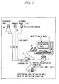
- FIG. 1 shows a view of a system architecture of an information system in a first embodiment of the present invention.
- This information system includes sensors 3A through 3C, etc. installed at an entrance hall of a building (house), a garage, a kitchen door and the like, a controller 1 connected via a communication cable to these sensors, an output device 4 connected to the controller 1 and receiving a predetermined notification from the controller 1 on the basis of states of the sensors 3A, etc., and a personal computer 2.
- the personal computer 2 also receives the notification from the controller 1 in the same way as the output device 4 does.
- the sensors 3A, etc. which are installed at the entrance hall, the garage, the kitchen door and so on, detect whether a visitor is there or not, a door opening/closing state, whether a car exists, enters and exits or not, etc., and notifies the controller 1 of a detected state.
- the sensors 3A, etc. are, for example, an infrared-ray sensor for detecting an existence of a person, a contact switch for detecting whether the door is opened or closed, an area sensor for detecting an existence of the car, and so forth.
- the sensors 3A, etc. input the detected states to input terminals of the controller 1 via the communication cable by use of an ON or OFF signal.
- the controller 1 always monitors the signals coming from the sensors 3A at its input terminals each identified by a terminal number. Then, when a state variation occurs in each sensor, for example, when detecting the visitor, etc., the controller 1 notifies the personal computer 2 or a predetermined output device 4, etc. of the terminal number of the input terminal and of a purport that the state variation has been detected by the sensor corresponding to this input terminal.
- the controller 1 is a device for gathering pieces of information from the sensors 3A, etc., determining which device should be notified of, and giving the notification in a way that switches over a destination of the notification each time.
- the controller 1 has a built-in CPU and is pre-installed with a control program to be executed by the CPU.
- the controller 1 further has a built-in function of sending a mail to the destination of the notification.
- the destination of the notification by the controller 1 may also be a cellular phone.
- the controller 1 also includes a function of permitting a flow of electric current and therefore, if a device is operated by the electric current in the same way as a notification-oriented lamp is, enables this device to be utilized as the output device 4 shown in FIG. 1. Furthermore, the controller 1 is capable of detecting a device which is under operating, from a plurality of output devices 4 and also capable of being controlled by the personal computer 2.
- the output device 4 has functions of transferring the notification from the controller 1 to a user through, for instance, user's own five senses such as a visual sense, an auditory sense, a tactile sense and so on.
- the output device 4 may be exemplified such as the notification-oriented lamp that emits predetermined light, a buzzer that emits a predetermined sound, a vibrator that transfers a receipt of the notification from the controller 1 to the user, a voice output device that reads the notification in voice, a display device that outputs characters or an image, and so forth.
- the output device 4 may also be a mail receipt notifying device such as a mascot robot having a mail receiving function, and so on.
- a mail receipt notifying device such as a mascot robot having a mail receiving function, and so on.
- the mascot robot performs a predetermined action, which is effective in notifying through the visual sense.
- the personal computer 2 upon the notification from the controller 1, displays the state transitions detected by the sensors 3A, etc. on the display device in character, image, voice and so forth.
- a configuration and an operation of the personal computer 2 are widely known, and hence the explanations thereof are omitted.
- the sensors 3A, etc. perform communications with the controller 1 via the communication cable (e.g., a LAN cable or a telephone cable, etc.).
- the sensors to which such a generalized cable is connectable are employed, whereby the cable can be laid to an arbitrary length and can be extended, and physical restrictions of an installation range of connected devices, etc. are obviated.
- the controller 1 in the present embodiment has the plurality of input terminals to which the plurality of sensors are connected. Further, the controller 1 in the present embodiment has the plurality of output terminals to which the plurality of personal computers 2 or the plurality of output devices 4 can be connected.
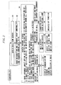
- FIG. 2 shows an outline of a notifying destination switchover procedure by the controller 1.
- the controller at first, obtains data from the sensors 3A, etc. via the respective input terminals (S1).
- the controller 1 recognizes a type of the corresponding sensor, a place at which setting up thereof, etc. from the terminal number of the input terminal. Moreover, the controller 1 judges based on a signal from this sensor whether the abnormality occurs or not. Then, the controller 1 adds the terminal number of the input terminal to the data (sensor data) from each sensor, and thus transfers the sensor data to the personal computer 2 (S2). This transfer enables the personal computer 2 to process the sensor data.
- the controller 1 judges an option of the notifying destination, and judges a present state of the notifying destination designated by this option (S3).
- S3 judges a present state of the notifying destination designated by this option.
- the controller 1 and the personal computer 2 may check a started status for each other from a predetermined output signal (indicating, e.g., a ready status, a standby status and so on).
- the controller 1 sends to the personal computer 2 a notification or an e-mail purporting that the abnormality has occurred.
- the sensor data are processed not by the personal computer 2 but by the controller 1, and a result of this processing can be displayed on the personal computer 2.
- the personal computer 2 when detecting the receipt of the notification, the e-mail or the sensor data, displays a notification window and emits a sound or a voice (S4).
- the controller 1 sends to the mail receipt notifying device the notification or the e-mail purporting that the abnormality has occurred.
- the mail receipt notifying device when detecting the e-mail for the user, notifies the user of this purport through the sound, the light, the action, etc. (S5).
- the controller 1 sends the notification purporting that the abnormality has occurred to the optical lamp or other connected device, or alternatively outputs a predetermined drive current thereto.
- other connected device is operated by the inputted current (S6).
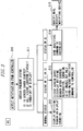
- FIG. 3 is a diagram showing an outline of the output function of the personal computer 2.
- the personal computer 2 in the present embodiment detects the notification given from the controller 1 and outputs various pieces of information to the user.
- the personal computer 2 detects the notification given from the controller 1 (S10). Then, the personal computer 2 acquires a present self-status (S11).
- the status herein connotes, e.g., 1) a started status of a screen saver, 2) a halt status (a suspend status), 3) a power-off status of the display, and so forth. Then, the personal computer 2 outputs pieces of information corresponding to these statuses.
- the personal computer 2 displays the notification window on the display device (display). Further, the personal computer 2 emits a sound (sound) corresponding to this notification window (S12).
- the personal computer 2 stops the screen saver. Further, the personal computer 2, when in the suspend status, restores from the suspend status. Then, the personal computer 2 displays the notification window, and gets the sound emitted, which corresponds to the notification window (S13).
- confirmation though not shown in FIG. 3, may also be received from the user when outputting in S12 and S13.
- the user may be prompted to click a confirmation button displayed on the display device by use of an unillustrated pointing device.
- the personal computer 2 may notify the controller 1 of whether the confirmation is made or not.
- the controller 1, if unable to obtain the confirmation from the user via the personal computer 2, may send the notification to other output device, e.g., the mail receipt notifying device.
- the personal computer 2 sends a substitute command to the controller 1.
- the substitute command connotes a notification given to the controller, purporting that the personal computer can not effect the predetermined output.
- the controller 1 when receiving the substitute command from the personal computer 2, sends the notification to other output device, e.g., the mail receipt notifying device (S15).
- the personal computer 2 may, in S13 in FIG. 3, even if unable to restore from the suspend status, transfer the substitute command to the controller 1.
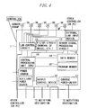
- FIG. 4 is a block diagram of hardware of the controller 1.
- the controller 1 includes a LAN control circuit 11, a filter circuit 12, a sensor signal processing circuit 13, a data memory 14, a program memory 15, an output control device 16, a DC power ON/OFF circuit 17 and a CPU 10.
- the LAN control circuit 11 reads the sensor data from a sensor group of the sensors 3A through 3F via the communication cable, and outputs the sensor data to output ports connected to the filter circuit 12, the CPU 10 or other controller (including the personal computer 2, etc.). Namely, the LAN control circuit 11 provided a function as a switch for outputting the signals of the predetermined input ports to the predetermined output ports.
- the filter circuit 12 effects filtering of the sensor data inputted from the LAN control circuit 11, thereby executing removal of noises, etc..
- the sensor signal processing circuit 13 performs sampling of the sensor data with a predetermined sampling period, and thus generates digital data.
- the generated digital data are stored together with the terminal number of the input terminal on the data memory 14 under the control of the CPU 10.
- the program memory 15 is stored with a program executed by the CPU 10.
- the CPU 10 executes this program, thereby providing a function as the controller 1.
- the CPU 10 stores the sensor data given from the sensors 3A through 3F on the data memory 14. Further, the CPU 10, based on the sensor data, drives the output control device 16 or the DC power ON/OFF circuit 17, and transmits the notification, the e-mail or the drive current to the notifying destination.
- the output control device 16 is, for example, a LAN board, etc., and sends the predetermined notification or the e-mail, etc. in response to a command given from the CPU 10.
- the DC power ON/OFF circuit 17 inputs the direct current to the notifying destination in response to a command given from the CPU 10.
- the CPU 10 notifies the user of a variation of the sensor data through the optical lamp, the buzzer and so forth.
- controller 1 is connected to other controller or PC, etc. via the LAN control circuit 11 or an external LAN input device.
- the first controller is connected to the second controller via the LAN control circuit 11 or the external LAN input device.
- the CPU 10 of the first controller 1 gives initial values of usable terminal numbers to a CPU of the second controller through the communications between the controllers.
- the CPU of the second controller may assign the terminal numbers to the input terminals to which pieces of sensor data from the respective sensors are inputted, wherein the given terminal numbers are set as the initial values.
- FIG. 5 is a flowchart showing the notifying destination switchover process by the controller 1.
- the CPU 10 within the controller 1 executes the computer program stored on the program memory 15, thereby actualizing this notifying destination switchover process.
- the CPU 10 detects abnormality from information given from the sensor (S21).
- the detection of the abnormality implies that the sensor detects a change from a closed state of the door of the entrance hall or the kitchen door, etc. to an unclosed state, the sensor at the entrance hall or the kitchen door, etc. detects a figure (person), and so forth.
- the CPU 10 judges whether the notifying destination about this abnormality is designated or not (S22). When the notifying destination is designated, the CPU 10 notifies the designated notifying destination. Further, the CPU 10 flickers the lamp provided on the controller 1 (S23).
- the CPU 10 judges whether or not the user confirms the notification at the notifying destination (S24).
- the confirmation of the notification connotes such a case that the user presses the predetermined confirmation button at the notifying destination.
- the notifying destination sends a response of gaining the confirmation back to the controller 1.
- the notifying destination may send this response by, e.g., the e-mail.
- the CPU 10 executes a notification completing process and returns to the standby status (S25). While on the other hand, when the response about the confirmation by the user is not obtained, the CPU 10 returns the control to S23. The processes in S23 and S24 are repeated till the confirmation by the user is obtained.
- the CPU 10 moves to the automatic mode. Further, when judging the notifying destination not to be set in S22, the CPU 10 likewise moves to the automatic mode.
- the CPU 10 gives the notification preferentially to the personal computer 2. This is because, if the user engages in working for a long period of time by use of information device such as the personal computer 2, etc., or if the user concentrates the attention on such a type of working, the user might often overlook the notification given other than on the display device of the information device under working. Moreover, there is a case of being capable of effectively notifying the disabled persons in their auditory sense by displaying the notification on the display device of the personal computer 2, etc..
- the CPU 10 judges whether or not the personal computer is started or not (S26). Subsequently, when the personal computer 2 is started, the CPU 10 sends the notification to the personal computer 2. Further, the CPU 10 flickers the lamp provided on the controller 1 (S27). At this time, the notification window is displayed on the personal computer 2.
- the CPU 10 judges whether or not the user confirms the notification on the personal computer 2 (S28).
- the confirmation of the notification implies that the user presses the predetermined confirmation button, e.g., an object on the display device of the personal computer 2 by using the pointing device, and so forth.
- the personal computer 2 sends the response of gaining the confirmation back to the controller 1.
- the CPU 10 executes the notification completing process and returns to the standby status (S29). While on the other hand, when the response about the confirmation by the user is not obtained, the CPU 10 returns the control to S27. The processes in S27 and S28 are repeated till the confirmation by the user is obtained.
- the CPU 10 moves to a judging process in S30. Further, when judging the personal computer 2 not to be started in S26, the CPU 10 likewise moves to the judging process in S30. In the judging process in S30, the CPU judges whether or not there is any connected device under operation (S30).
- the CPU 10 When judging in S30 that there is the connected device under operation, the CPU 10 sends the notification to this connected device. Further, the CPU 10 flickers the lamp provided on the controller 1 (S31). Then, the CPU 10 judges whether or not the user confirms the notification at the notifying destination (S32).
- the connected device supports the mail receiving function
- a mail is delivered to this connected device.
- the connected device having received the mail starts operating.
- the controller 1 checks whether the mail is downloaded into a mail server of the user, thereby making it possible to detect whether the user confirms the connected device, i.e., the mail or not. Further, a mail unsealing confirmed notification may also be transmitted from the connected device.
- the connected device is a device actuated by a Dc power source
- the notification is given simply by causing a flow of the electric current, however, as for this point, the confirmation is made by detecting whether this connected device is active or not. Namely, if the electric current once flows, the connected device invariably must become active. Therefore, if the connected device remains active (operating) even after a predetermined period of time has elapsed, it may be judged that the user does not yet confirm.
- the CPU 10 executes the notification completing process and returns to the standby status (S33). While on the other hand, when the response about the confirmation by the user is not obtained, the CPU 10 returns the control to S31. The processes in S31 and S32 are repeated till the confirmation by the user is obtained.
- the CPU 10 moves to a process in S34. Further, when judging the connected device of the notifying destination not to be started in S30, the CPU 10 likewise moves to the process in S34.
- the CPU 10 In the case of obtaining the user's confirmation by executing the notifying process, the CPU 10 returns to the standby status defined as a normal status in preparation for a next process (S35). As described above, the CPU checks the mail server, etc. or receives the mail unsealing confirmed notification and so on, thereby making it possible to detect whether the user has confirmed the mail or not.
- the notifying destination when the abnormality or the state variation is detected from the sensor data, the notifying destination can be flexibly switched over. For instance, the notification of the abnormality or the state variation can be given in a way that selects the started device or the personal computer 2 under operation, etc. from the preset notifying destinations.
- the security system based on an individual level can be configured by combining the LAN cable, the telephone line and the generalized sensors.
- the present information system not only the persons in normal health but also the disabled persons in their visual sense, auditory sense, etc. can be notified of the abnormality or the state variation by combining the output devices of the notifying destination.
- the system can be easily extended by increasing the number of controllers.
- the sensor or the notifying device (the output device 4 in FIG. 1) can be installed in the place desired by the user without any restriction of a length of the cable, and it is feasible to reduce the possibility of overlooking the occurrence of the abnormality and the state variation.
- the sensors 3A, etc. are connected to the controller 1 via the communication cable such as the LAN cable and so on.
- the sensors 3A, etc. may also be connected to the controller 1 via wireless communications using a wireless LAN, Bluetooth, etc..
- the embodiment discussed above has exemplified the system for notifying of the abnormality or the state variation in the sensor data in a way that connects the plurality of sensors to the single controller 1.
- the embodiment of the present invention is not, however, limited to this configuration.
- An available system is, for example, that one sensor is connected to one controller 1.
- the first embodiment has exemplified the information system including the controller 1 for detecting the abnormality or the state variation in the sensor data and notifying the predetermined notifying destination of it.
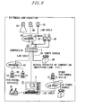
- FIG. 6 shows a view of a system architecture of the information system in the second embodiment of the present invention.
- This information system also includes, as in the case of the first embodiment, the sensors 3A through 3C, etc., the controller 1, the personal computer 2, the output device 4, the mail receipt notifying device and so on.
- the personal computer 2 has the same input terminals as those of the controller 1. Then, the sensor data are inputted (via communication cables L1, L2 and L3) to the input terminals of the personal computer 2 in parallel with the controller 1.
- the personal computer 2 includes a communication port (a communication cable L4) for communicating with the controller 1.
- the personal computer 2 monitors a status of the controller 1 via the communication cable L4 at a predetermined timing, e.g., immediately after the personal computer 2 has been started, or at a predetermined interval. Then, the personal computer 2, when detecting a fault or disorder of the controller 1, executes the substitute function of the controller 1.
- the fault or the disorder of the controller 1 implies, for instance, a case in which the controller 1 does not respond to a query from the personal computer 2.
- the output terminals of both of the controller 1 and the personal computer 2 are connected to a hub 5, wherein the plurality of output devices 4 or mail receipt notifying devices can be notified of a message via the hub 5.
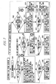
- FIG. 7 is a flowchart showing a controller substitute process by the personal computer 2. This process is executed by the personal computer 2 as a substitute for the controller 1 when the personal computer 2 detects a fault of the controller 1.
- the personal computer 2 detects the abnormality from the information given from the sensors (S41).
- the personal computer 2 judges whether or not the notifying destination is designated with respect to this abnormality (S42). When the notifying destination is designated, the personal computer 2 executes a process corresponding to the designated notifying destination (S43).
- the personal computer 2 displays the notifying window on the display device of the personal computer 2 itself. Further, if the notifying destination excludes the personal computer 2, the personal computer 2 notifies the designated notifying destination. Moreover, the personal computer 2 causes the notifying destination to display a confirmation window.
- the confirmation window connotes a window on which the user is notified of the abnormality or the state variation, etc. and is prompted to input that the user has recognized a content of the notification. A confirmation button by which the user inputs the confirmation is provided on the confirmation window.
- the personal computer 2 judges whether or not the user has confirmed the notification on the notifying window of the personal computer 2 itself or on the confirmation window at the notifying destination described above (S44).
- the personal computer 2 executes the notification completing process, and returns to the standby status (S45). While on the other hand, when the response about the confirmation by the user is not obtained, the personal computer 2 returns the control to S43. The processes in S43 and S44 are repeated till the confirmation by the user is obtained.
- the personal computer 2 moves to the automatic mode. Further, when judging the notifying destination not to be set in S42, the personal computer 2 likewise moves to the automatic mode.
- the personal computer 2 judges whether there is any other connected device or not (S46). Then, when there is the device connected to the personal computer 2, the personal computer 2 notifies the connected device and makes this connected device to display the confirmation window (S47).
- the personal computer 2 judges whether or not the user has confirmed the notification on the confirmation window of the aforementioned connected device (S48).
- the personal computer 2 executes the notification completing process, and returns to the standby status (S49). While on the other hand, when the response about the confirmation by the user is not obtained, the personal computer 2 returns the control to S47. The processes in S47 and S48 are repeated till the confirmation by the user is obtained.
- the personal computer 2 moves to a judging process in S50. Further, when judging in S46 that there is not any other connected device, the personal computer 2 likewise moves to the judging process in S50. In the judging process in S50, the personal computer 2 judges whether or not there is any connected device under operation.
- the personal computer 2 When judging in S50 that there is the connected device under operation, the personal computer 2 sends the notification to the connected device and makes this connected device display the confirmation window (S51). Then, the CPU 10 judges whether or not the user has confirmed the notification at the notifying destination (S52).
- the personal computer 2 executes the notification completing process and returns to the standby status (S53). While on the other hand, when the response about the confirmation by the user is not obtained, the personal computer 2 returns the control to S51. The processes in S51 and S52 are repeated till the confirmation by the user is obtained.
- the personal computer 2 moves to a process in S54. Further, when judging in S50 that none of the connected devices at the notifying destination are started, the personal computer 2 likewise moves to the process in S54.
- the personal computer 2 detects this fault and can, as the substitute for the controller 1, notify the user of the abnormality or the state variation in the sensor data.
- the personal computer 2 executes the substitute function when the controller 1 falls into the fault or disorder. If the controller 1 falls into neither the fault nor the disorder, however, the personal computer 2 may execute the function of the controller 1. Namely, both of the controller 1 and the personal computer 2 may monitor the sensors.
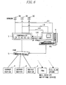
- FIG. 8 is a view of a system architecture of the information system according to the third embodiment.
- the sensors 3A, etc. are connected to the controller 1 via a hub 5A. Some (e.g., sensors 3D, 3E, etc. in FIG. 8) among the sensors may, however, be connected directly to the controller 1.
- the signals from the plurality of sensors 3A through 3C are inputted to one single input terminal of the controller 1 via the hub 5A.
- This configuration makes it possible to detect a synthesized signal of the sensor signals of the sensors installed in a plurality of positions.
- the sensors 3A through 3C are installed in different positions within the entrance hall, thereby enabling enhancement of certainty of detecting a detection object (e.g., a visitor or trespasser, etc.).
- the controller 1 is connected via the hub 5A to the output devices 4.
- Part (e.g., the output device 4B, etc. in FIG. 8) of the output devices may, however, be connected directly to the controller 1.
- a flexible extension of the notifying destinations can be attained through the hub.
- a storage medium readable by a computer, etc. can be stored with the program for making the computer, other device, machine, etc. (which will hereinafter be referred to as the computer, etc.) actualize any one of the aforementioned functions. Then, the computer, etc. reads and executes the program on this storage medium, whereby the function thereof can be provided.
- the storage medium readable by the computer connotes a storage medium capable of storing information such as data, programs, etc. electrically, magnetically, optically and mechanically or by chemical action, which can be read by the computer.
- What is demountable out of the computer, etc. among those storage mediums may be, e.g., a flexible disc, a magneto-optic disc, a CD-ROM, a CD-R/W, a DVD, a DAT, an 8mm tape, a memory card, etc.
- a hard disc a ROM (Read Only Memory) and so on is given as storage medium fixed in the computer, etc..
- the above program may be stored in the hard disc and the memory of the computer, etc., and can be distributed to other computers via communication media.
- the program is transmitted as data communication signals embodied in carrier waves via the communication media.
- the computer receiving the distribution thereof can be made to provide the aforementioned function.
- the communication media may be any one of cable communication mediums such as metallic cables including a coaxial cable and a twisted pair cable, optical communication cables, or wireless communication media such as satellite communications, ground wave wireless communications, etc..
- cable communication mediums such as metallic cables including a coaxial cable and a twisted pair cable, optical communication cables, or wireless communication media such as satellite communications, ground wave wireless communications, etc.
- the carrier waves are electromagnetic waves for modulating the data communication signals, or the light.
- the carrier waves may, however, be DC signals.
- the data communication signal takes a base band waveform with no carrier wave.
- the data communication signal embodied in the carrier wave may be any one of a modulated broadband signal and an unmodulated base band signal (corresponding to a case of setting a DC signal having a voltage of 0 as a carrier wave).
- the present invention can be applied to a manufacturing industry and a sales industry of housing equipment, welfare equipment, building management equipment, a plant system, management equipment in a laboratory, office management equipment, etc., and to a service industry utilizing these types of equipment.
Landscapes
- Business, Economics & Management (AREA)
- Emergency Management (AREA)
- Physics & Mathematics (AREA)
- General Physics & Mathematics (AREA)
- Health & Medical Sciences (AREA)
- Public Health (AREA)
- Alarm Systems (AREA)
- Fire Alarms (AREA)
Abstract
A sensor monitor comprises a sensor monitoring section for
monitoring a sensor, notifying section for notifying a
first notifying destination of a predetermined state when
sensed by the sensor, notification confirming section for
confirming that the notification has been recognized by the
first notifying destination, and control section for
deciding a second notifying destination in case of the
incapability of confirming that the notification has been
recognized, and notifying the notifying means of it.
Description
The present invention relates to an information
apparatus for notifying of information given from sensors.
A field of welfare has hitherto been provided with a
notification system for notifying, e.g., a disabled person
in his or her auditory sense of an arrival of a visitor
through an optical lamp when the visitor presses an
interphone. Further, there has been provided a system for
detecting boiling of a cooking utensil, baby crying in a
house, etc., and notifying of it through a monitor or a
notifying lamp.
In the conventional systems, however, the following
problems arise. For example, an individual using a personal
computer in concentration for a long period of time is hard
to monitor the monitor and the notifying lamp at all times,
and therefore has a high possibility of overlooking the
notification.
Further, in the conventional system, a dedicated
cable is often formed integrally with the sensor, and the
cable has a limit of its length, wherein a notification
range is confined. For instance, a general type of visitor
notification system for the disabled persons in their
auditory sense is that the interphone at an entrance hall
is connected by a cable directly to a light emitting lamp
in a room. Therefore, a majority of this type of systems
can not be installed unless within a space between the
entrance hall and rooms close to the entrance hall.
Furthermore, there are many systems requiring special
pieces of hardware that are not easily available. For
instance, the notification system for welfare provided in a
self-governing body, etc. is generally difficult for
acquisition, and the number of systems provided for each
person is limited.
Moreover, the majority of conventional systems are
constructed by fixing dedicated sensors and dedicated
notifying apparatus, and do not come under a category of
universal-free. For example, the notification through a
sound is not suited to the disabled persons in their
auditory sense. Further, a visual notification through
light is not suited to the disabled persons in their visual
sense.
Still further, generally, the notification system
utilizing the sensors is easy to be specialized for the
purpose of security, and is small of a degree of freedom
and extensibility of arrangement.
The present invention was devised in view of the
problems inherent in the prior arts described above. Namely,
it is an object of the present invention to provide a
technology capable of surely notifying a user of
information from generalized sensors by flexibly connecting
these sensors to a notifying destination without using
special systems and apparatus specialized for the purpose
of security.
To accomplish the above object, the present
invention adopts the following means. To be specific, the
present invention is a monitoring apparatus comprising a
sensor monitoring unit monitoring a sensor, a notifying
unit notifying, when the sensor detects a predetermined
state, a first notifying destination of this purport, a
notification confirming unit confirming that the
notification has been recognized at the first notifying
destination, and a control unit determining, if unable to
confirm that the notification has been recognized, a second
notifying destination and making the notifying means give
the notification to the second notifying destination.
The sensor monitoring unit is connected to the sensor
via, e.g., an input terminal and obtains output data of the
sensor. The notifying unit notifies the first notifying
destination that the sensor has detected the predetermined
state. Further, the notification confirming unit checks
whether or not the notification has been recognized at the
first notifying destination. Then, if unable to recognize,
the control unit determines the second notifying
destination, and causes the notifying unit to notify the
second notifying destination.
Preferably, the monitoring apparatus may further
comprise a notifying destination recording unit recording a
plurality of notifying destinations, and an operation
detecting unit detecting an operation state of the
notifying destination, wherein the control unit may
determine the second notifying destination on the basis of
the operation states of the plurality of notifying
destinations.
Thus, the second notifying destination is determined
based on the operation states from within the plurality of
notifying destinations, and it is therefore possible to
select the notifying destination exhibiting a high
possibility that the notification is to be recognized.
Further, the present invention may also be a
processing apparatus connected to a monitoring apparatus
comprising a sensor monitoring unit monitoring a sensor, a
notifying unit notifying, when the sensor detects a
predetermined state, a first notifying destination of this
purport, a notification confirming unit confirming that the
notification has been recognized at the notifying
destination, and a control unit determining, if unable to
confirm that the notification as been recognized, a second
notifying destination and making the notifying means give
the notification to the second notifying destination, the
processing apparatus being connected to the sensor, and
receiving the notification from the monitoring apparatus,
the processing apparatus comprising a communication unit
communicating with the monitoring apparatus, an operation
judging unit judging an operation state of the monitoring
apparatus, and a substitute unit functioning, if the
monitoring apparatus is not under operation, as the sensor
monitoring unit, the notifying unit and the control unit.
Thus, the processing apparatus, which is originally
constructed to receive the notification from the
aforementioned monitoring apparatus, is made to become the
substitute for the functions of the monitoring apparatus,
whereby the processing apparatus can monitor the sensor if
the monitoring apparatus falls into a fault or disorder,
and reliability on the system can be enhanced.
Moreover, the present invention may also be a system
configured by combining the sensor with the monitoring
apparatus. Still further, the present invention may also be
a system configured by combining the above system with
aforementioned processing apparatus.
Yet further, the present invention may be a method by
which a computer, other apparatus, machine, etc. executes
any of the processes described above. Moreover, the present
invention may also be a program making the computer, other
apparatus, machine, etc. actualize any one of the functions
or steps or processes described above. Furthermore, the
present invention may also be a storage medium stored with
such a program that is readable by the computer, other
apparatus, machine and so forth.
A preferred embodiment of the present invention will
hereinafter be described with reference to the drawings.
FIG. 1 shows a view of a system architecture of an
information system in a first embodiment of the present
invention. This information system includes sensors 3A
through 3C, etc. installed at an entrance hall of a
building (house), a garage, a kitchen door and the like, a
controller 1 connected via a communication cable to these
sensors, an output device 4 connected to the controller 1
and receiving a predetermined notification from the
controller 1 on the basis of states of the sensors 3A, etc.,
and a personal computer 2. In the present embodiment, the
personal computer 2 also receives the notification from the
controller 1 in the same way as the output device 4 does.
The sensors 3A, etc., which are installed at the
entrance hall, the garage, the kitchen door and so on,
detect whether a visitor is there or not, a door
opening/closing state, whether a car exists, enters and
exits or not, etc., and notifies the controller 1 of a
detected state. The sensors 3A, etc. are, for example, an
infrared-ray sensor for detecting an existence of a person,
a contact switch for detecting whether the door is opened
or closed, an area sensor for detecting an existence of the
car, and so forth. The sensors 3A, etc. input the detected
states to input terminals of the controller 1 via the
communication cable by use of an ON or OFF signal.
The controller 1 always monitors the signals coming
from the sensors 3A at its input terminals each identified
by a terminal number. Then, when a state variation occurs
in each sensor, for example, when detecting the visitor,
etc., the controller 1 notifies the personal computer 2 or
a predetermined output device 4, etc. of the terminal
number of the input terminal and of a purport that the
state variation has been detected by the sensor
corresponding to this input terminal.
Namely, the controller 1 is a device for gathering
pieces of information from the sensors 3A, etc.,
determining which device should be notified of, and giving
the notification in a way that switches over a destination
of the notification each time. For actualizing these
functions, the controller 1 has a built-in CPU and is pre-installed
with a control program to be executed by the CPU.
The controller 1 further has a built-in function of sending
a mail to the destination of the notification. Hence, the
destination of the notification by the controller 1 may
also be a cellular phone.
Moreover, the controller 1 also includes a function
of permitting a flow of electric current and therefore, if
a device is operated by the electric current in the same
way as a notification-oriented lamp is, enables this device
to be utilized as the output device 4 shown in FIG. 1.
Furthermore, the controller 1 is capable of detecting a
device which is under operating, from a plurality of output
devices 4 and also capable of being controlled by the
personal computer 2.
The output device 4 has functions of transferring the
notification from the controller 1 to a user through, for
instance, user's own five senses such as a visual sense, an
auditory sense, a tactile sense and so on. The output
device 4 may be exemplified such as the notification-oriented
lamp that emits predetermined light, a buzzer that
emits a predetermined sound, a vibrator that transfers a
receipt of the notification from the controller 1 to the
user, a voice output device that reads the notification in
voice, a display device that outputs characters or an image,
and so forth.
Furthermore, the output device 4 may also be a mail
receipt notifying device such as a mascot robot having a
mail receiving function, and so on. In the case of such a
construction, when abnormality occurs, the mascot robot
performs a predetermined action, which is effective in
notifying through the visual sense.
The personal computer 2, upon the notification from
the controller 1, displays the state transitions detected
by the sensors 3A, etc. on the display device in character,
image, voice and so forth. A configuration and an operation
of the personal computer 2 are widely known, and hence the
explanations thereof are omitted.
The sensors 3A, etc. perform communications with the
controller 1 via the communication cable (e.g., a LAN cable
or a telephone cable, etc.). The sensors to which such a
generalized cable is connectable are employed, whereby the
cable can be laid to an arbitrary length and can be
extended, and physical restrictions of an installation
range of connected devices, etc. are obviated.
The controller 1 in the present embodiment has the
plurality of input terminals to which the plurality of
sensors are connected. Further, the controller 1 in the
present embodiment has the plurality of output terminals to
which the plurality of personal computers 2 or the
plurality of output devices 4 can be connected.
FIG. 2 shows an outline of a notifying destination
switchover procedure by the controller 1. The controller 1,
at first, obtains data from the sensors 3A, etc. via the
respective input terminals (S1).
Then, the controller 1 recognizes a type of the
corresponding sensor, a place at which setting up thereof,
etc. from the terminal number of the input terminal.
Moreover, the controller 1 judges based on a signal from
this sensor whether the abnormality occurs or not. Then,
the controller 1 adds the terminal number of the input
terminal to the data (sensor data) from each sensor, and
thus transfers the sensor data to the personal computer 2
(S2). This transfer enables the personal computer 2 to
process the sensor data.
Next, the controller 1 judges an option of the
notifying destination, and judges a present state of the
notifying destination designated by this option (S3). The
following is a detailed description of the judging process.
For example, whether the notifying destination such
as the personal computer 2 or the mail receipt notifying
device, etc. has been started or not can be judged by
executing a ping command defined as an application program
of TCP/IP. Further, the controller 1 and the personal
computer 2 may check a started status for each other from a
predetermined output signal (indicating, e.g., a ready
status, a standby status and so on).
Subsequently, the controller 1 sends to the personal
computer 2 a notification or an e-mail purporting that the
abnormality has occurred. As a result, the sensor data are
processed not by the personal computer 2 but by the
controller 1, and a result of this processing can be
displayed on the personal computer 2.
In this respect, the personal computer 2, when
detecting the receipt of the notification, the e-mail or
the sensor data, displays a notification window and emits a
sound or a voice (S4).
Further, the controller 1 sends to the mail receipt
notifying device the notification or the e-mail purporting
that the abnormality has occurred. In this point, the mail
receipt notifying device, when detecting the e-mail for the
user, notifies the user of this purport through the sound,
the light, the action, etc. (S5).
Moreover, the controller 1 sends the notification
purporting that the abnormality has occurred to the optical
lamp or other connected device, or alternatively outputs a
predetermined drive current thereto. In response to this,
other connected device is operated by the inputted current
(S6).
FIG. 3 is a diagram showing an outline of the output
function of the personal computer 2. The personal computer
2 in the present embodiment detects the notification given
from the controller 1 and outputs various pieces of
information to the user.
The personal computer 2, to begin with, detects the
notification given from the controller 1 (S10). Then, the
personal computer 2 acquires a present self-status (S11).
The status herein connotes, e.g., 1) a started status of a
screen saver, 2) a halt status (a suspend status), 3) a
power-off status of the display, and so forth. Then, the
personal computer 2 outputs pieces of information
corresponding to these statuses.
For instance, when the personal computer 2 is in none
of those statuses (this is called a normal status), the
personal computer 2 displays the notification window on the
display device (display). Further, the personal computer 2
emits a sound (sound) corresponding to this notification
window (S12).
Moreover, for example, when the screen saver is in
the started status, the personal computer 2 stops the
screen saver. Further, the personal computer 2, when in the
suspend status, restores from the suspend status. Then, the
personal computer 2 displays the notification window, and
gets the sound emitted, which corresponds to the
notification window (S13).
Note that confirmation, though not shown in FIG. 3,
may also be received from the user when outputting in S12
and S13. For example, the user may be prompted to click a
confirmation button displayed on the display device by use
of an unillustrated pointing device. The personal computer
2 may notify the controller 1 of whether the confirmation
is made or not. The controller 1, if unable to obtain the
confirmation from the user via the personal computer 2, may
send the notification to other output device, e.g., the
mail receipt notifying device.
Moreover, for instance, in case a power supply of the
display is switched off, the personal computer 2 sends a
substitute command to the controller 1. The substitute
command connotes a notification given to the controller,
purporting that the personal computer can not effect the
predetermined output. The controller 1, when receiving the
substitute command from the personal computer 2, sends the
notification to other output device, e.g., the mail receipt
notifying device (S15).
It is to be noted that the personal computer 2 may,
in S13 in FIG. 3, even if unable to restore from the
suspend status, transfer the substitute command to the
controller 1.
FIG. 4 is a block diagram of hardware of the
controller 1. As in FIG. 4, the controller 1 includes a LAN
control circuit 11, a filter circuit 12, a sensor signal
processing circuit 13, a data memory 14, a program memory
15, an output control device 16, a DC power ON/OFF circuit
17 and a CPU 10.
The LAN control circuit 11 reads the sensor data from
a sensor group of the sensors 3A through 3F via the
communication cable, and outputs the sensor data to output
ports connected to the filter circuit 12, the CPU 10 or
other controller (including the personal computer 2, etc.).
Namely, the LAN control circuit 11 provided a function as a
switch for outputting the signals of the predetermined
input ports to the predetermined output ports.
The filter circuit 12 effects filtering of the sensor
data inputted from the LAN control circuit 11, thereby
executing removal of noises, etc..
The sensor signal processing circuit 13 performs
sampling of the sensor data with a predetermined sampling
period, and thus generates digital data. The generated
digital data are stored together with the terminal number
of the input terminal on the data memory 14 under the
control of the CPU 10.
The program memory 15 is stored with a program
executed by the CPU 10. The CPU 10 executes this program,
thereby providing a function as the controller 1.
For example, the CPU 10, as described above, stores
the sensor data given from the sensors 3A through 3F on the
data memory 14. Further, the CPU 10, based on the sensor
data, drives the output control device 16 or the DC power
ON/OFF circuit 17, and transmits the notification, the e-mail
or the drive current to the notifying destination.
The output control device 16 is, for example, a LAN
board, etc., and sends the predetermined notification or
the e-mail, etc. in response to a command given from the
CPU 10. The DC power ON/OFF circuit 17 inputs the direct
current to the notifying destination in response to a
command given from the CPU 10. Thus, the CPU 10 notifies
the user of a variation of the sensor data through the
optical lamp, the buzzer and so forth.
Further, the controller 1 is connected to other
controller or PC, etc. via the LAN control circuit 11 or an
external LAN input device.
Moreover, in the case of desiring to connect a
greater number of sensors than the number of the input
terminals provided in the single controller, these extra
sensors are connected to a second controller. Further, the
first controller is connected to the second controller via
the LAN control circuit 11 or the external LAN input device.
At this time, the CPU 10 of the first controller 1 gives
initial values of usable terminal numbers to a CPU of the
second controller through the communications between the
controllers. The CPU of the second controller may assign
the terminal numbers to the input terminals to which pieces
of sensor data from the respective sensors are inputted,
wherein the given terminal numbers are set as the initial
values.
FIG. 5 is a flowchart showing the notifying
destination switchover process by the controller 1. The CPU
10 within the controller 1 executes the computer program
stored on the program memory 15, thereby actualizing this
notifying destination switchover process.
In this process, to start with, the CPU 10 detects
abnormality from information given from the sensor (S21).
Herein, the detection of the abnormality implies that the
sensor detects a change from a closed state of the door of
the entrance hall or the kitchen door, etc. to an unclosed
state, the sensor at the entrance hall or the kitchen door,
etc. detects a figure (person), and so forth.
Upon the detection of the abnormality, the CPU 10
judges whether the notifying destination about this
abnormality is designated or not (S22). When the notifying
destination is designated, the CPU 10 notifies the
designated notifying destination. Further, the CPU 10
flickers the lamp provided on the controller 1 (S23).
Then, the CPU 10 judges whether or not the user
confirms the notification at the notifying destination
(S24). The confirmation of the notification connotes such a
case that the user presses the predetermined confirmation
button at the notifying destination. When the confirmation
described above is made by the user, the notifying
destination sends a response of gaining the confirmation
back to the controller 1. The notifying destination may
send this response by, e.g., the e-mail.
When the response about the confirmation by the user
is sent from the notifying destination, the CPU 10 executes
a notification completing process and returns to the
standby status (S25). While on the other hand, when the
response about the confirmation by the user is not obtained,
the CPU 10 returns the control to S23. The processes in S23
and S24 are repeated till the confirmation by the user is
obtained.
Then, if there is none of the confirmation by the
user even after a predetermined period of time has elapsed,
i.e., if the user is not aware of the notification, the CPU
10 moves to the automatic mode. Further, when judging the
notifying destination not to be set in S22, the CPU 10
likewise moves to the automatic mode.
According to the present embodiment, in the automatic
mode, the CPU 10 gives the notification preferentially to
the personal computer 2. This is because, if the user
engages in working for a long period of time by use of
information device such as the personal computer 2, etc.,
or if the user concentrates the attention on such a type of
working, the user might often overlook the notification
given other than on the display device of the information
device under working. Moreover, there is a case of being
capable of effectively notifying the disabled persons in
their auditory sense by displaying the notification on the
display device of the personal computer 2, etc..
Then, the CPU 10 judges whether or not the personal
computer is started or not (S26). Subsequently, when the
personal computer 2 is started, the CPU 10 sends the
notification to the personal computer 2. Further, the CPU
10 flickers the lamp provided on the controller 1 (S27). At
this time, the notification window is displayed on the
personal computer 2.
Then, the CPU 10 judges whether or not the user
confirms the notification on the personal computer 2 (S28).
The confirmation of the notification implies that the user
presses the predetermined confirmation button, e.g., an
object on the display device of the personal computer 2 by
using the pointing device, and so forth. When such a type
of confirmation by the user is given, the personal computer
2 sends the response of gaining the confirmation back to
the controller 1.
When the response about the confirmation by the user
is sent from the personal computer 2, the CPU 10 executes
the notification completing process and returns to the
standby status (S29). While on the other hand, when the
response about the confirmation by the user is not obtained,
the CPU 10 returns the control to S27. The processes in S27
and S28 are repeated till the confirmation by the user is
obtained.
Then, if there is none of the confirmation by the
user even after the predetermined period of time has
elapsed, i.e., if the user is not aware of the notification,
the CPU 10 moves to a judging process in S30. Further, when
judging the personal computer 2 not to be started in S26,
the CPU 10 likewise moves to the judging process in S30. In
the judging process in S30, the CPU judges whether or not
there is any connected device under operation (S30).
When judging in S30 that there is the connected
device under operation, the CPU 10 sends the notification
to this connected device. Further, the CPU 10 flickers the
lamp provided on the controller 1 (S31). Then, the CPU 10
judges whether or not the user confirms the notification at
the notifying destination (S32).
For instance, if the connected device supports the
mail receiving function, at first, a mail is delivered to
this connected device. The connected device having received
the mail starts operating. At this time, the controller 1
checks whether the mail is downloaded into a mail server of
the user, thereby making it possible to detect whether the
user confirms the connected device, i.e., the mail or not.
Further, a mail unsealing confirmed notification may also
be transmitted from the connected device.
Further, if the connected device is a device actuated
by a Dc power source, the notification is given simply by
causing a flow of the electric current, however, as for
this point, the confirmation is made by detecting whether
this connected device is active or not. Namely, if the
electric current once flows, the connected device
invariably must become active. Therefore, if the connected
device remains active (operating) even after a
predetermined period of time has elapsed, it may be judged
that the user does not yet confirm.
When the response about the confirmation by the user
is sent from the notifying destination, the CPU 10 executes
the notification completing process and returns to the
standby status (S33). While on the other hand, when the
response about the confirmation by the user is not obtained,
the CPU 10 returns the control to S31. The processes in S31
and S32 are repeated till the confirmation by the user is
obtained.
Then, if there is no confirmation by the user even
after the predetermined period of time has elapsed, i.e.,
if the user is not aware of the notification, the CPU 10
moves to a process in S34. Further, when judging the
connected device of the notifying destination not to be
started in S30, the CPU 10 likewise moves to the process in
S34.
If unable to obtain the confirmation from the
notifying destination in all the connected devices as in
the case of an absence of the user, etc., and if the user
carries a cellular phone, a mail is transmitted as a final
means (S34). Whereas if not, there is taken a measure of
continuing to flicker the lamp of the controller till the
user gets aware of it.
In the case of obtaining the user's confirmation by
executing the notifying process, the CPU 10 returns to the
standby status defined as a normal status in preparation
for a next process (S35). As described above, the CPU
checks the mail server, etc. or receives the mail unsealing
confirmed notification and so on, thereby making it
possible to detect whether the user has confirmed the mail
or not.
As described above, according to the present
information system, when the abnormality or the state
variation is detected from the sensor data, the notifying
destination can be flexibly switched over. For instance,
the notification of the abnormality or the state variation
can be given in a way that selects the started device or
the personal computer 2 under operation, etc. from the
preset notifying destinations.
Moreover, according to the present information system,
the security system based on an individual level can be
configured by combining the LAN cable, the telephone line
and the generalized sensors.
Further, according to the present information system,
not only the persons in normal health but also the disabled
persons in their visual sense, auditory sense, etc. can be
notified of the abnormality or the state variation by
combining the output devices of the notifying destination.
Still further, according to the present information
system, even when exceeding the number (the number of input
terminals) receivable by one single controller with the
increased number of sensors, the system can be easily
extended by increasing the number of controllers. Yet
further, according to the present information system in the
present embodiment, the sensor or the notifying device (the
output device 4 in FIG. 1) can be installed in the place
desired by the user without any restriction of a length of
the cable, and it is feasible to reduce the possibility of
overlooking the occurrence of the abnormality and the state
variation.
In the embodiment discussed above, the sensors 3A,
etc. are connected to the controller 1 via the
communication cable such as the LAN cable and so on. As a
substitute for this construction, however, the sensors 3A,
etc. may also be connected to the controller 1 via wireless
communications using a wireless LAN, Bluetooth, etc..
The embodiment discussed above has exemplified the
system for notifying of the abnormality or the state
variation in the sensor data in a way that connects the
plurality of sensors to the single controller 1. The
embodiment of the present invention is not, however,
limited to this configuration. An available system is, for
example, that one sensor is connected to one controller 1.
A second embodiment of the present invention will
hereinafter be explained with reference to the drawings in
FIGS. 6 and 7. The first embodiment has exemplified the
information system including the controller 1 for detecting
the abnormality or the state variation in the sensor data
and notifying the predetermined notifying destination of it.
Explained in the second embodiment is an information
system in which the personal computer 1, if the controller
1 falls into a fault in the above information system (the
first embodiment), becomes a substitute for the function of
the controller 1. Other elements and the operations are
similar to those in the first embodiment. Such being the
case, the same components are marked with the same numerals
and symbols, and their explanations are omitted. Further,
the drawings in FIGS. 1 through 5 are referred to according
to the necessity.
FIG. 6 shows a view of a system architecture of the
information system in the second embodiment of the present
invention. This information system also includes, as in the
case of the first embodiment, the sensors 3A through 3C,
etc., the controller 1, the personal computer 2, the output
device 4, the mail receipt notifying device and so on.
In the second embodiment, however, the personal
computer 2 has the same input terminals as those of the
controller 1. Then, the sensor data are inputted (via
communication cables L1, L2 and L3) to the input terminals
of the personal computer 2 in parallel with the controller
1.
Further, the personal computer 2 includes a
communication port (a communication cable L4) for
communicating with the controller 1. The personal computer
2 monitors a status of the controller 1 via the
communication cable L4 at a predetermined timing, e.g.,
immediately after the personal computer 2 has been started,
or at a predetermined interval. Then, the personal computer
2, when detecting a fault or disorder of the controller 1,
executes the substitute function of the controller 1.
Herein, the fault or the disorder of the controller 1
implies, for instance, a case in which the controller 1
does not respond to a query from the personal computer 2.
Moreover, the output terminals of both of the
controller 1 and the personal computer 2 are connected to a
hub 5, wherein the plurality of output devices 4 or mail
receipt notifying devices can be notified of a message via
the hub 5.
FIG. 7 is a flowchart showing a controller substitute
process by the personal computer 2. This process is
executed by the personal computer 2 as a substitute for the
controller 1 when the personal computer 2 detects a fault
of the controller 1.
In this controller substitute process, to begin with,
the personal computer 2 detects the abnormality from the
information given from the sensors (S41).
When the abnormality is detected, the personal
computer 2 judges whether or not the notifying destination
is designated with respect to this abnormality (S42). When
the notifying destination is designated, the personal
computer 2 executes a process corresponding to the
designated notifying destination (S43).
For instance, if the notifying destination is the
personal computer 2, the personal computer 2 displays the
notifying window on the display device of the personal
computer 2 itself. Further, if the notifying destination
excludes the personal computer 2, the personal computer 2
notifies the designated notifying destination. Moreover,
the personal computer 2 causes the notifying destination to
display a confirmation window. Herein, the confirmation
window connotes a window on which the user is notified of
the abnormality or the state variation, etc. and is
prompted to input that the user has recognized a content of
the notification. A confirmation button by which the user
inputs the confirmation is provided on the confirmation
window.
Then, the personal computer 2 judges whether or not
the user has confirmed the notification on the notifying
window of the personal computer 2 itself or on the
confirmation window at the notifying destination described
above (S44).
When there is the confirmation by the user, the
personal computer 2 executes the notification completing
process, and returns to the standby status (S45). While on
the other hand, when the response about the confirmation by
the user is not obtained, the personal computer 2 returns
the control to S43. The processes in S43 and S44 are
repeated till the confirmation by the user is obtained.
Then, if there is none of the confirmation by the
user even after a predetermined period of time has elapsed,
i.e., if the user is not aware of the notification, the
personal computer 2 moves to the automatic mode. Further,
when judging the notifying destination not to be set in S42,
the personal computer 2 likewise moves to the automatic
mode.
According to the second embodiment, in the automatic
mode, the personal computer 2 judges whether there is any
other connected device or not (S46). Then, when there is
the device connected to the personal computer 2, the
personal computer 2 notifies the connected device and makes
this connected device to display the confirmation window
(S47).
Then, the personal computer 2 judges whether or not
the user has confirmed the notification on the confirmation
window of the aforementioned connected device (S48).
When there is the confirmation by the user, the
personal computer 2 executes the notification completing
process, and returns to the standby status (S49). While on
the other hand, when the response about the confirmation by
the user is not obtained, the personal computer 2 returns
the control to S47. The processes in S47 and S48 are
repeated till the confirmation by the user is obtained.
Then, if there is none of the confirmation by the
user even after a predetermined period of time has elapsed,
i.e., if the user is not aware of the notification, the
personal computer 2 moves to a judging process in S50.
Further, when judging in S46 that there is not any other
connected device, the personal computer 2 likewise moves to
the judging process in S50. In the judging process in S50,
the personal computer 2 judges whether or not there is any
connected device under operation.
When judging in S50 that there is the connected
device under operation, the personal computer 2 sends the
notification to the connected device and makes this
connected device display the confirmation window (S51).
Then, the CPU 10 judges whether or not the user has
confirmed the notification at the notifying destination
(S52).
When the response about the confirmation by the user
is sent from the notifying destination, the personal
computer 2 executes the notification completing process and
returns to the standby status (S53). While on the other
hand, when the response about the confirmation by the user
is not obtained, the personal computer 2 returns the
control to S51. The processes in S51 and S52 are repeated
till the confirmation by the user is obtained.
Then, if there is none of the confirmation by the
user even after a predetermined period of time has elapsed,
i.e., if the user is not aware of the notification, the
personal computer 2 moves to a process in S54. Further,
when judging in S50 that none of the connected devices at
the notifying destination are started, the personal
computer 2 likewise moves to the process in S54.
The processes in S54 and S55 are executed in a case
such as the absence of the user, etc. and are the same as
those in S34 and S35 in FIG. 5 according to the first
embodiment (the personal computer 2, however, gets the
confirmation window displayed instead of flickering the
lamp).
As discussed above, according to the information
system in the second embodiment, if the controller 1 falls
into the fault, the personal computer 2 detects this fault
and can, as the substitute for the controller 1, notify the
user of the abnormality or the state variation in the
sensor data.
In the second embodiment discussed above, the
personal computer 2 executes the substitute function when
the controller 1 falls into the fault or disorder. If the
controller 1 falls into neither the fault nor the disorder,
however, the personal computer 2 may execute the function
of the controller 1. Namely, both of the controller 1 and
the personal computer 2 may monitor the sensors.
A third embodiment of the present invention will be
explained with reference to FIG. 8. FIG. 8 is a view of a
system architecture of the information system according to
the third embodiment.
In this information system, the sensors 3A, etc. are
connected to the controller 1 via a hub 5A. Some (e.g.,
sensors 3D, 3E, etc. in FIG. 8) among the sensors may,
however, be connected directly to the controller 1.
In the architecture in FIG. 8, the signals from the
plurality of sensors 3A through 3C are inputted to one
single input terminal of the controller 1 via the hub 5A.
This configuration makes it possible to detect a
synthesized signal of the sensor signals of the sensors
installed in a plurality of positions. For example, the
sensors 3A through 3C are installed in different positions
within the entrance hall, thereby enabling enhancement of
certainty of detecting a detection object (e.g., a visitor
or trespasser, etc.).
Moreover, the controller 1 is connected via the hub
5A to the output devices 4. Part (e.g., the output device
4B, etc. in FIG. 8) of the output devices may, however, be
connected directly to the controller 1. Thus, a flexible
extension of the notifying destinations can be attained
through the hub.
A storage medium readable by a computer, etc. can be
stored with the program for making the computer, other
device, machine, etc. (which will hereinafter be referred
to as the computer, etc.) actualize any one of the
aforementioned functions. Then, the computer, etc. reads
and executes the program on this storage medium, whereby
the function thereof can be provided.
Herein, the storage medium readable by the computer,
etc. connotes a storage medium capable of storing
information such as data, programs, etc. electrically,
magnetically, optically and mechanically or by chemical
action, which can be read by the computer. What is
demountable out of the computer, etc. among those storage
mediums may be, e.g., a flexible disc, a magneto-optic disc,
a CD-ROM, a CD-R/W, a DVD, a DAT, an 8mm tape, a memory
card, etc..
Further, a hard disc, a ROM (Read Only Memory) and so
on is given as storage medium fixed in the computer, etc..
Furthermore, the above program may be stored in the
hard disc and the memory of the computer, etc., and can be
distributed to other computers via communication media. In
this case, the program is transmitted as data communication
signals embodied in carrier waves via the communication
media. Then, the computer receiving the distribution
thereof can be made to provide the aforementioned function.
Herein, the communication media may be any one of
cable communication mediums such as metallic cables
including a coaxial cable and a twisted pair cable, optical
communication cables, or wireless communication media such
as satellite communications, ground wave wireless
communications, etc..
Further, the carrier waves are electromagnetic waves
for modulating the data communication signals, or the light.
The carrier waves may, however, be DC signals. In this case,
the data communication signal takes a base band waveform
with no carrier wave. Accordingly, the data communication
signal embodied in the carrier wave may be any one of a
modulated broadband signal and an unmodulated base band
signal (corresponding to a case of setting a DC signal
having a voltage of 0 as a carrier wave).
The present invention can be applied to a
manufacturing industry and a sales industry of housing
equipment, welfare equipment, building management equipment,
a plant system, management equipment in a laboratory,
office management equipment, etc., and to a service
industry utilizing these types of equipment.
Claims (9)
- A monitoring apparatus comprising:a sensor monitoring unit monitoring a sensor;a notifying unit notifying, when said sensor detects a predetermined state, a first notifying destination of this purport;a notification confirming unit confirming that the notification has been recognized at said first notifying destination; anda control unit determining, if unable to confirm that the notification has been recognized, a second notifying destination and making said notifying means give the notification to said second notifying destination.
- A monitoring apparatus according to claim 1, further comprising:wherein said control unit determines said second notifying destination on the basis of the operation states of said plurality of notifying destinations.a notifying destination recording unit recording a plurality of notifying destinations; andan operation detecting unit detecting an operation state of said notifying destination,
- A processing apparatus connected to a monitoring apparatus comprising a sensor monitoring unit monitoring a sensor, a notifying unit notifying, when said sensor detects a predetermined state, a first notifying destination of this purport, a notification confirming unit confirming that the notification has been recognized at said notifying destination, and a control unit determining, if unable to confirm that the notification as been recognized, a second notifying destination and making said notifying means give the notification to the second notifying destination, said processing apparatus being connected to said sensor and receiving the notification from said monitoring apparatus, said processing apparatus comprising:a communication unit communicating with said monitoring apparatus;an operation judging unit judging an operation state of said monitoring apparatus; anda substitute unit functioning, if said monitoring apparatus is not under operation, as said sensor monitoring unit, said notifying unit and said control unit.
- A monitoring system comprising a monitoring apparatus for monitoring a sensor and a processing apparatus for receiving a notification from said monitoring apparatus,said monitoring apparatus including:a sensor monitoring unit monitoring a sensor;a notifying unit notifying, when said sensor detects a predetermined state, a first notifying destination of this purport;a notification confirming unit confirming that the notification has been recognized at said notifying destination; anda control unit determining, if unable to confirm that the notification as been recognized, a second notifying destination and making said notifying means give the notification to said second notifying destination,said processing apparatus including:a communication unit communicating with said monitoring apparatus;an operation judging unit judging an operation state of said monitoring apparatus; anda substitute unit functioning, if said monitoring apparatus is not under operation, as said sensor monitoring unit, said notifying unit and said control unit.
- A sensor monitoring method comprising:a step of monitoring a sensor;a step of notifying, when said sensor detects a predetermined state, a first notifying destination of this purport;a step of confirming that the notification has been recognized at said first notifying destination; anda control step of determining, if unable to confirm that the notification has been recognized, a second notifying destination and making said notifying means give the notification to said second notifying destination.
- A sensor monitoring method according to claim 5, further comprising:wherein said control step involves determining said second notifying destination on the basis of the operation states of said plurality of notifying destinations.a step of referring to a plurality of notifying destinations; anda step of detecting an operation state of said notifying destination,
- A program for making a computer execute:a step of monitoring a sensor;a step of notifying, when said sensor detects a predetermined state, a first notifying destination of this purport;a step of confirming that the notification has been recognized at said first notifying destination; anda control step of determining, if unable to confirm that the notification has been recognized, a second notifying destination and getting the notification given to said second notifying destination.
- A program according to claim 7, further making said computer execute:wherein said control step involves determining said second notifying destination on the basis of the operation states of said plurality of notifying destinations.a step of referring to a plurality of notifying destinations; anda step of detecting an operation state of said notifying destination,
- A program for making a computer, connected to a monitoring apparatus comprising a sensor monitoring unit monitoring a sensor, a notifying unit notifying, when said sensor detects a predetermined state, a first notifying destination of this purport, a notification confirming unit confirming that the notification has been recognized at said notifying destination, and a control unit determining, if unable to confirm that the notification as been recognized, a second notifying destination and making said notifying means give the notification to said second notifying destination, said computer being connected to said sensor, execute:a step of communicating with said monitoring apparatus;a step of judging an operation state of said monitoring apparatus; anda step of functioning, if said monitoring apparatus is not under operation, as said sensor monitoring unit, said notifying unit and said control unit.
Applications Claiming Priority (1)
| Application Number | Priority Date | Filing Date | Title |
|---|---|---|---|
| PCT/JP2002/007002 WO2004008409A1 (en) | 2002-07-10 | 2002-07-10 | Sensor monitor, monitor system, sensor monitor method, and program |
Publications (2)
| Publication Number | Publication Date |
|---|---|
| EP1521223A1 true EP1521223A1 (en) | 2005-04-06 |
| EP1521223A4 EP1521223A4 (en) | 2008-03-05 |
Family
ID=30022636
Family Applications (1)
| Application Number | Title | Priority Date | Filing Date |
|---|---|---|---|
| EP02745917A Withdrawn EP1521223A4 (en) | 2002-07-10 | 2002-07-10 | SENSOR MONITOR, MONITOR SYSTEM, SENSOR MONITORING METHOD, AND PROGRAM |
Country Status (5)
| Country | Link |
|---|---|
| US (1) | US7196620B2 (en) |
| EP (1) | EP1521223A4 (en) |
| JP (1) | JP3886996B2 (en) |
| AU (1) | AU2002318647A1 (en) |
| WO (1) | WO2004008409A1 (en) |
Cited By (1)
| Publication number | Priority date | Publication date | Assignee | Title |
|---|---|---|---|---|
| EP2340531A1 (en) * | 2008-10-09 | 2011-07-06 | UTC Fire & Security Americas Corporation, Inc. | System and method for operating a security system |
Families Citing this family (31)
| Publication number | Priority date | Publication date | Assignee | Title |
|---|---|---|---|---|
| CA2595949C (en) * | 2005-03-12 | 2009-10-06 | Lutron Electronics Co., Inc. | Handheld programmer for lighting control system |
| US20090273433A1 (en) * | 2005-03-12 | 2009-11-05 | Rigatti Christopher J | Method of automatically programming a new ballast on a digital ballast communication link |
| JP4670556B2 (en) * | 2005-09-12 | 2011-04-13 | ソニー株式会社 | Communication apparatus and method |
| US20090287120A1 (en) | 2007-12-18 | 2009-11-19 | Searete Llc, A Limited Liability Corporation Of The State Of Delaware | Circulatory monitoring systems and methods |
| US9672471B2 (en) * | 2007-12-18 | 2017-06-06 | Gearbox Llc | Systems, devices, and methods for detecting occlusions in a biological subject including spectral learning |
| US8280484B2 (en) * | 2007-12-18 | 2012-10-02 | The Invention Science Fund I, Llc | System, devices, and methods for detecting occlusions in a biological subject |
| US20100036268A1 (en) * | 2008-08-07 | 2010-02-11 | Searete Llc, A Limited Liability Corporation Of The State Of Delaware | Circulatory monitoring systems and methods |
| US20100036269A1 (en) * | 2008-08-07 | 2010-02-11 | Searete Llc, A Limited Liability Corporation Of The State Of Delaware | Circulatory monitoring systems and methods |
| US20090281412A1 (en) * | 2007-12-18 | 2009-11-12 | Searete Llc, A Limited Liability Corporation Of The State Of Delaware | System, devices, and methods for detecting occlusions in a biological subject |
| US9717896B2 (en) | 2007-12-18 | 2017-08-01 | Gearbox, Llc | Treatment indications informed by a priori implant information |
| US20100036263A1 (en) * | 2008-08-07 | 2010-02-11 | Searete Llc, A Limited Liability Corporation Of The State Of Delaware | Circulatory monitoring systems and methods |
| US20100036209A1 (en) * | 2008-08-07 | 2010-02-11 | Searete Llc, A Limited Liability Corporation Of The State Of Delaware | Circulatory monitoring systems and methods |
| US20090287109A1 (en) * | 2008-05-14 | 2009-11-19 | Searete Llc, A Limited Liability Corporation Of The State Of Delaware | Circulatory monitoring systems and methods |
| US8636670B2 (en) | 2008-05-13 | 2014-01-28 | The Invention Science Fund I, Llc | Circulatory monitoring systems and methods |
| US20090287076A1 (en) * | 2007-12-18 | 2009-11-19 | Boyden Edward S | System, devices, and methods for detecting occlusions in a biological subject |
| US8760262B2 (en) | 2009-03-20 | 2014-06-24 | Lutron Electronics Co., Inc. | Method of automatically programming a load control device using a remote identification tag |
| JP2011054009A (en) * | 2009-09-03 | 2011-03-17 | Hozumi Yamamura | Identification tag system |
| US9978238B2 (en) | 2012-09-21 | 2018-05-22 | Google Llc | Visitor options at an entryway to a smart-home |
| US10735216B2 (en) | 2012-09-21 | 2020-08-04 | Google Llc | Handling security services visitor at a smart-home |
| US9711036B2 (en) | 2012-09-21 | 2017-07-18 | Google Inc. | Leveraging neighborhood to handle potential visitor at a smart-home |
| US9600645B2 (en) | 2012-09-21 | 2017-03-21 | Google Inc. | Smart invitation handling at a smart-home |
| US9881474B2 (en) | 2012-09-21 | 2018-01-30 | Google Llc | Initially detecting a visitor at a smart-home |
| US9626841B2 (en) | 2012-09-21 | 2017-04-18 | Google Inc. | Occupant notification of visitor interaction with a doorbell at a smart-home |
| US9640055B2 (en) | 2012-09-21 | 2017-05-02 | Google Inc. | Interacting with a detected visitor at an entryway to a smart-home |
| US9953514B2 (en) * | 2012-09-21 | 2018-04-24 | Google Llc | Visitor feedback to visitor interaction with a doorbell at a smart-home |
| US9652912B2 (en) | 2012-09-21 | 2017-05-16 | Google Inc. | Secure handling of unsupervised package drop off at a smart-home |
| US9959727B2 (en) | 2012-09-21 | 2018-05-01 | Google Llc | Handling visitor interaction at a smart-home in a do not disturb mode |
| US10332059B2 (en) | 2013-03-14 | 2019-06-25 | Google Llc | Security scoring in a smart-sensored home |
| US9960929B2 (en) | 2012-09-21 | 2018-05-01 | Google Llc | Environmental sensing with a doorbell at a smart-home |
| US12232850B2 (en) * | 2015-06-14 | 2025-02-25 | Facense Ltd. | Doorway system that utilizes wearable-based health state verifications |
| CN105872057A (en) * | 2016-04-01 | 2016-08-17 | 大连翼兴信息技术有限公司 | Urban building automation remote monitoring and management system |
Family Cites Families (16)
| Publication number | Priority date | Publication date | Assignee | Title |
|---|---|---|---|---|
| JPH05250591A (en) | 1992-03-04 | 1993-09-28 | Matsushita Electric Ind Co Ltd | Home security equipment |
| JPH05347672A (en) | 1992-06-15 | 1993-12-27 | Nippon Telegr & Teleph Corp <Ntt> | Sensor telephone set |
| JPH08106407A (en) * | 1994-10-07 | 1996-04-23 | Fuji Elelctrochem Co Ltd | Abnormal alarm device |
| JP3409230B2 (en) * | 1995-06-27 | 2003-05-26 | 松下電工株式会社 | Wireless emergency call system |
| US5729197A (en) * | 1996-02-22 | 1998-03-17 | Ultra Communications Corporation | Automatic, self-triggering alarm processing system and method |
| AU3021597A (en) * | 1996-06-07 | 1998-01-07 | Telalert, Inc. | Programmed telephone security system |
| DE29711886U1 (en) * | 1997-06-30 | 1997-09-11 | Daten- und Prozeßtechnik GmbH, 14532 Stahnsdorf | Device for reporting faults and process data in technical systems |
| DE19823813B4 (en) * | 1998-03-20 | 2009-05-07 | Rud. Prey GmbH Aufzüge und Feuerwehrtechnik | Method and accident management system for automatic notification of a fault that has occurred |
| US6564056B1 (en) * | 1999-08-03 | 2003-05-13 | Avaya Technology Corp. | Intelligent device controller |
| AU4136701A (en) * | 1999-11-30 | 2001-06-12 | Joseph N. D'amico | Security system linked to the internet |
| JP2001297384A (en) | 2000-04-13 | 2001-10-26 | Nippon Intelligence Factory Co Ltd | Home security system and method |
| US6580950B1 (en) * | 2000-04-28 | 2003-06-17 | Echelon Corporation | Internet based home communications system |
| JP4620218B2 (en) | 2000-05-25 | 2011-01-26 | 勲 榎本 | Home security system |
| KR100359827B1 (en) * | 2000-11-27 | 2002-11-07 | 엘지전자 주식회사 | Network method and apparatus for home appliance |
| US6693530B1 (en) * | 2001-10-16 | 2004-02-17 | At&T Corp. | Home security administration platform |
| US7039698B2 (en) * | 2002-06-18 | 2006-05-02 | Bellsouth Intellectual Property Corporation | Notification device interaction |
-
2002
- 2002-07-10 EP EP02745917A patent/EP1521223A4/en not_active Withdrawn
- 2002-07-10 WO PCT/JP2002/007002 patent/WO2004008409A1/en not_active Ceased
- 2002-07-10 AU AU2002318647A patent/AU2002318647A1/en not_active Abandoned
- 2002-07-10 JP JP2004521094A patent/JP3886996B2/en not_active Expired - Fee Related
-
2004
- 2004-11-22 US US10/992,904 patent/US7196620B2/en not_active Expired - Fee Related
Cited By (1)
| Publication number | Priority date | Publication date | Assignee | Title |
|---|---|---|---|---|
| EP2340531A1 (en) * | 2008-10-09 | 2011-07-06 | UTC Fire & Security Americas Corporation, Inc. | System and method for operating a security system |
Also Published As
| Publication number | Publication date |
|---|---|
| US20050156728A1 (en) | 2005-07-21 |
| WO2004008409A1 (en) | 2004-01-22 |
| JP3886996B2 (en) | 2007-02-28 |
| AU2002318647A1 (en) | 2004-02-02 |
| JPWO2004008409A1 (en) | 2005-11-10 |
| EP1521223A4 (en) | 2008-03-05 |
| US7196620B2 (en) | 2007-03-27 |
Similar Documents
| Publication | Publication Date | Title |
|---|---|---|
| US7196620B2 (en) | Sensor monitoring apparatus, monitoring system, sensor monitoring method and program | |
| US20090289787A1 (en) | Residential security cluster with associated alarm interconnects | |
| US8988215B1 (en) | Monitoring system which tracks and analyzes characteristics of a mobile device that monitors a property with a monitoring application | |
| EP2353153B1 (en) | A system for tracking a presence of persons in a building, a method and a computer program product | |
| US20070273487A1 (en) | System and method for determining the location of a resident during an emergency within a monitored area having a plurality of residences | |
| WO2014098993A1 (en) | Alarm detection and notification system | |
| WO2007105553A1 (en) | Monitoring system, terminal device of the monitoring system, main control device, and method and program for registering terminal device | |
| US11276292B2 (en) | Recording activity detection | |
| KR20060029436A (en) | Security system | |
| WO1999021152A1 (en) | System for monitoring remote device status | |
| US7315258B2 (en) | System and method for programming a code of an emergency call transmitter | |
| JP2004129280A (en) | Remote control system, control method and program thereof | |
| KR100674574B1 (en) | Network security information transmission system and method using wireless communication | |
| KR101773524B1 (en) | State information notification module and management system for elder who lives alone using the same | |
| JP2002344660A (en) | Health problem detection and notice system for person in need of nursing care | |
| JP4345469B2 (en) | Monitoring system and program thereof | |
| JP6103162B1 (en) | Parent device of monitored person monitoring system, operation state monitoring method of parent device, child apparatus of monitored person monitoring system, operation state monitoring method of child device, and monitored person monitoring system | |
| JP2765719B2 (en) | Security terminal equipment setting registration system | |
| KR200414554Y1 (en) | Projector Remote Management System | |
| KR100750955B1 (en) | Projector remote management system and method | |
| Dewsbury et al. | Home technology systems | |
| JP2005084863A (en) | Monitoring/reporting system | |
| JP5107115B2 (en) | Security equipment | |
| JP5508099B2 (en) | Maintenance system, security control device, maintenance device, and communication method | |
| CN113672155A (en) | Self-service operating system, method and medium based on VR technology |
Legal Events
| Date | Code | Title | Description |
|---|---|---|---|
| PUAI | Public reference made under article 153(3) epc to a published international application that has entered the european phase |
Free format text: ORIGINAL CODE: 0009012 |
|
| 17P | Request for examination filed |
Effective date: 20041222 |
|
| AK | Designated contracting states |
Kind code of ref document: A1 Designated state(s): AT BE BG CH CY CZ DE DK EE ES FI FR GB GR IE IT LI LU MC NL PT SE SK TR |
|
| RBV | Designated contracting states (corrected) |
Designated state(s): DE FR GB |
|
| A4 | Supplementary search report drawn up and despatched |
Effective date: 20080206 |
|
| 17Q | First examination report despatched |
Effective date: 20080613 |
|
| STAA | Information on the status of an ep patent application or granted ep patent |
Free format text: STATUS: THE APPLICATION IS DEEMED TO BE WITHDRAWN |
|
| 18D | Application deemed to be withdrawn |
Effective date: 20090504 |