EP1521204B1 - Bildverarbeitungsvorrichtung zur Objekterkennung - Google Patents
Bildverarbeitungsvorrichtung zur Objekterkennung Download PDFInfo
- Publication number
- EP1521204B1 EP1521204B1 EP04255779A EP04255779A EP1521204B1 EP 1521204 B1 EP1521204 B1 EP 1521204B1 EP 04255779 A EP04255779 A EP 04255779A EP 04255779 A EP04255779 A EP 04255779A EP 1521204 B1 EP1521204 B1 EP 1521204B1
- Authority
- EP
- European Patent Office
- Prior art keywords
- partial
- images
- image
- comparison target
- orthogonal system
- Prior art date
- Legal status (The legal status is an assumption and is not a legal conclusion. Google has not performed a legal analysis and makes no representation as to the accuracy of the status listed.)
- Expired - Lifetime
Links
Images

Classifications
-
- G—PHYSICS
- G06—COMPUTING OR CALCULATING; COUNTING
- G06V—IMAGE OR VIDEO RECOGNITION OR UNDERSTANDING
- G06V10/00—Arrangements for image or video recognition or understanding
- G06V10/40—Extraction of image or video features
- G06V10/50—Extraction of image or video features by performing operations within image blocks; by using histograms, e.g. histogram of oriented gradients [HoG]; by summing image-intensity values; Projection analysis
- G06V10/507—Summing image-intensity values; Histogram projection analysis
-
- G—PHYSICS
- G06—COMPUTING OR CALCULATING; COUNTING
- G06V—IMAGE OR VIDEO RECOGNITION OR UNDERSTANDING
- G06V10/00—Arrangements for image or video recognition or understanding
- G06V10/40—Extraction of image or video features
- G06V10/42—Global feature extraction by analysis of the whole pattern, e.g. using frequency domain transformations or autocorrelation
- G06V10/431—Frequency domain transformation; Autocorrelation
-
- G—PHYSICS
- G06—COMPUTING OR CALCULATING; COUNTING
- G06V—IMAGE OR VIDEO RECOGNITION OR UNDERSTANDING
- G06V30/00—Character recognition; Recognising digital ink; Document-oriented image-based pattern recognition
- G06V30/10—Character recognition
- G06V30/24—Character recognition characterised by the processing or recognition method
- G06V30/248—Character recognition characterised by the processing or recognition method involving plural approaches, e.g. verification by template match; Resolving confusion among similar patterns, e.g. "O" versus "Q"
- G06V30/2504—Coarse or fine approaches, e.g. resolution of ambiguities or multiscale approaches
Definitions
- the present invention relates to an image processor to be used for recognizing an object, such as a component, using a visual sensor, and more particularly to an image processor for recognizing the position and orientation of an object which could take various orientations based on images.
- the position and orientation of the object In order to handle objects (e.g. components) which are not accurately positioned, using such an automatic machine as a robot, the position and orientation of the object must be recognized.
- a method, which has been used for this, is that an object is photographed using an image sensing means (camera) of the visual sensor, and the position and orientation of the object is recognized from the acquired image data.
- the range of the position and orientation for the object which can be taken, particularly the range of orientations is wide in many cases, and in such a case, it is not easy to accurately recognize the position and orientation of the object.
- a recognition method which could be used for such a case is capturing sample images of the objects from various different directions in advance, comparing and collating the partial image extracted from the input image at each location with each sample image by pattern matching, and extracting the partial image having high consistency with one of the sample images, and detecting the positions of the targets.
- a new concept is introduced to combine an orthogonal transformation to the coarse-to-fine method, so as to further decrease calculation time while maintaining final extraction accuracy.
- the present invention divides each search stage of the coarse-to-fine method into a final search stage and a search stage up to this point (non-final search stage), where the dimensions of the orthogonal transformation are maintained at the demanded level in the final search stage, but the dimensions of the orthogonal transformation are permitted to drop in the non-final search stage, down to the level,in which it is sufficient if the position of the object can be recognized without error.
- the present invention concerning the final search stage among each search stage of the coarse-to-fine method, it is focused to the point where the dimensions of the orthogonal transformation directly relate to the final extraction accuracy, and both requirements, decreasing the operation load and maintaining extraction accuracy, are implemented by changing the level required for the dimensions of the orthogonal transformation.
- an image processor uses a plurality of sample images acquired by capturing an image of an object from a plurality of directions and which extracts one or more partial images from an input image that includes one or more images of the object, each extracted partial image having high consistency with a respective one of said sample images, the image processor comprising: a first computing means for applying an orthogonal transformation to each of said sample images based on a normalized orthogonal system composed of predetermined vectors, and determining a component group composed of component of each vector expressed in said normalized orthogonal system; means for selecting partial images corresponding to a plurality of predetermined areas in said input image, the selected partial images being comparison target images; means for selecting a subset of vectors from the vectors constituting said normalized orthogonal system and creating a partial normalized orthogonal system composed of said selected subset of vectors; second computing means for determining for each of the comparison target images a first partial component group composed of components of each vector expressed in said selected subset of vectors of said partial normalized orthogon
- the image processor according to the present invention may be constructed such that a plurality of partial images are selected near the previously extracted partial images as further new comparison target images, a further new partial normalized orthogonal system, of which the number of vectors is the same as or more than those of the previous partial normalized orthogonal system, is created, and the extraction of a partial image from the plurality of further new comparison target images is repeated once or more by using the second computing means and the extraction means for the plurality of further new comparison target images and the further new partial normalized orthogonal system.
- orthogonal transformation For the orthogonal transformation, Fourier transformation or discrete cosine transformation, for example, can be used.
- the components to be acquired by applying the orthogonal transformation to each of the sample images may become the main components of the sample images.
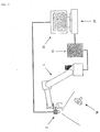
- Fig. 1 is a diagram depicting an outline of the system configuration according to the present embodiment.
- the reference numeral 1 indicates a robot (main body mechanical unit), and a camera 2 is installed at the tip of the arm of this robot as an image capturing means of the visual sensor.
- the operation of the robot 1 is controlled by the robot controller 10 which is connected to the robot 1.
- the image processor 20 is connected to the camera 2, and the image processor 20 is also connected to the robot controller 10 via the communication line.
- the image processor 20 comprises a hardware further comprising a CPU, memory, camera interface and communication interface, software to exchange commands with the camera 2 and the robot controller 10 and to transfer/receive image data, and software that includes programs for processing image data in the later mentioned modes and related parameters.
- the image processor 20 also has a display 21, so that the image captured by the camera 2, processed images thereof and later mentioned sample images can be displayed.
- a manual operation means e.g. teaching pendant, keyboard, mouse
- the image processor 20 is installed in the robot controller 10 and the image processor 20 in an ordinary format, so as to manually perform robot operation, input/edit and start/stop of a program, image capturing by the camera 2, loading of image data, and input/edit and start/stop of an image processing program, when necessary.
- the camera 2 captures an image when an image capturing/image data output command is received from the image processor 20, and inputs image data including the image of an object (e.g. component) W to the image processor 20.
- the image processor 20 executes image processing in a later mentioned mode by the processing program, and recognizes the object from the image.
- the robot controller 10 and the image processor 20 have general functions to transmit/receive data of the following (1) - (3) and execute the related processing while synchronizing with each other if necessary.
- one or more partial images having high consistency with one of the sample images is extracted from the input image in which one or more images of the object are included, and this procedure will now be described sequentially.
- sample object obtained by capturing images of an object (hereinafter referred to as sample object) which is the same kind as the target object W from a plurality of different directions.
- sample object is placed at an appropriate position and orientation, and the image is captured by the camera 2 while the robot takes a plurality of positions and orientations, and the sample image data is stored in the memory of the image processor 20.
- the robot position is stored in the memory of the image processor 20. The robot may be moved to a plurality of positions and orientations according to a pre-instructed operation, or by manual operation by an operator.
- a sample image When a sample image is captured, interrupting images should not be captured in the background of the sample object.
- the sample object is placed on a floor which has a different color and brightness than the sample object, and has no patterns, and the image thereof is captured.
- the sample object here may be one of the target objects to be used in an actual operation, or may be a dummy object of which shape and dimensions are the same as the actual object.
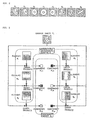
- each sample image is regarded as a vector on an appropriate vector space, and [this vector] is approximated by a linear combination of m number of vectors (elements), e 1 , ... , e m constituting the normalized orthogonal system in a partial space of the above vector space.
- m number of vectors are also called “elements” or “images” herein below.
- Fig. 3 is a diagram depicting a method for determining the component group by performing orthogonal transformation on each sample image using the provided normalized orthogonal system (computation by the first computing means).
- each sample image s ⁇ is given by the following approximate expression. s ⁇ ⁇ ⁇ ⁇ ⁇ 1 ⁇ e 1 + ... + ⁇ ⁇ m ⁇ e m
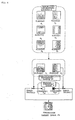
- Fig. 4 is a diagram depicting a method for selecting a plurality of comparison target images from the input image and extracting an image having high consistency with one of the sample images from the comparison target images
- Fig. 5 is a diagram depicting the computation executed in this method by the second computing means.
- a plurality of comparison target images are selected from the input image, which is an image captured such that at least one of the objects to be recognized is photographed, and a partial normalized orthogonal system is created from the above mentioned normalized orthogonal system E (see Fig. 3). Then, based on the partial normalized orthogonal system, orthogonal transformation is applied to the comparison target images, and a partial component group is determined for each comparison target image. This computation is performed by the second computing means (see Fig. 5).
- Fourier transformation or discrete cosine transformation for example, can be used. Fourier transformation or discrete cosine transformation for image data are well known, so a detailed description thereof is omitted.
- the comparison target image can also be handled as vectors of the linear space to which elements of the normalized orthogonal system and sample images belong.
- the partial component group corresponding to the comparison target image p ⁇ is ⁇ ⁇ , ( ⁇ ⁇ 1 , ... , ⁇ ⁇ i ).
- the comparison target image p ⁇ can be approximated by the following expression using the partial component group ⁇ ⁇ ' and the partial normalized orthogonal system E'. p ⁇ ⁇ ⁇ ⁇ ⁇ 1 ⁇ e 1 + ... + ⁇ ⁇ i ⁇ e i
- an image of which ⁇ ⁇ is small with respect to a certain ⁇ can be selected as an extracted image from the comparison target images.
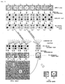
- Fig. 6 is a diagram depicting a method for selecting a plurality of new comparison target images near each extracted image in Fig. 4, creating a new partial normalized orthogonal system of which the number of elements is the same or more than that of the partial normalized orthogonal system in Fig. 4, and extracting an image having high consistency with one of the sample images from the new comparison target image by using the second computing means and the extraction means.
- the new comparison target images can also be handled as vectors of a linear space to which the elements of the normalized orthogonal system and the sample images belong.
- the new comparison target image q ⁇ can be approximated by the following expression using the partial component group ⁇ ⁇ " and the partial normalized orthogonal system E". q ⁇ ⁇ ⁇ ⁇ ⁇ ⁇ 1 ⁇ e 1 + ... + ⁇ ⁇ j ⁇ e j
- T ⁇ ⁇ ⁇ ⁇ 1 - ⁇ ⁇ ⁇ 1 2 + ... + ⁇ ⁇ j - ⁇ ⁇ j 2
- an image where T ⁇ is small (e.g. the minimum) with respect to ⁇ can be selected from the comparison target images.
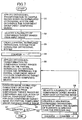
- Fig. 7 shows a flow chart depicting an outline of the processing to be performed in the image processor 20.
- the key point of each step is as follows.
- Step S1 Based on the data on the normalized orthogonal system (dimension m) stored in the memory in advance, orthogonal transformation is applied to each sample image, and a component group composed of the components of each element of this normalized orthogonal system is determined (calculation by first computing means).
- Step S2 Partial images corresponding to a plurality of predetermined areas in the input image are selected as the comparison target images respectively.
- Step S3 A partial normalized orthogonal system is created from the normalized orthogonal system.
- the partial normalized orthogonal system is the above mentioned E', and the dimension i thereof is set to m or less in advance.
- i is a maximum integer which does not exceed 2m/3.
- Step S4 The register value, as an index to indicate the search stage, is set to "-1" as an initial value.
- Step S5 Based on the partial normalized orthogonal system, orthogonal transformation is applied to each comparison target image, and a partial component group composed of components on each element of the partial normalized orthogonal system is determined for each comparison target image (calculation by second computing means).
- the partial normalized orthogonal system that is used here is the one determined in step S3 in the first processing cycle and the one determined in the later mentioned step S9 in the second processing cycle (second stage of searching).
- Step S6 Among the partial component group for each comparison target image determined in step S5 and the component group determined for each sample image, a comparison target image having high consistency with one of the sample images is extracted by comparison and collation with the partial component group composed of components corresponding to each element of each partial normalized orthogonal system.
- Step S7 It is checked whether the counter value is 0 or more, and processing ends if the judgment result is YES, or proceeds to step S8 if the judgment result is NO. In the first processing cycle, the result is naturally NO, so processing proceeds to step S8.
- Step S8 A plurality of partial images are selected near each extracted image determined in step S6 as new comparison target images.
- Step S9 A new partial normalized orthogonal system with more elements is created.
- the partial normalized orthogonal system is the above mentioned E", and the dimension j thereof is set to m or less and i or more in advance.
- j is a maximum integer which does not exceed (i + m)/2.
- Step S10 The register value, as an index to indicate the search stage, is incremented by 1, and processing returns to step S5.
- the judgment result becomes "YES", and processing ends.
- the comparison target image extracted in step S6 at the second time is selected as the best image.
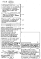
- Step U1 Based on the data on the normalized orthogonal system (dimension m) stored in memory in advance, orthogonal transformation is performed on each sample image, and a component group composed of components on each element of the normalized orthogonal system is determined, just like the above mentioned step S1 (calculation by first computing means).
- Step U2 Just like the above mentioned step S2, partial images corresponding to a plurality of predetermined areas in the input image are selected as the comparison target images respectively.
- Step U3 Just like the above mentioned step S3, a partial normalized orthogonal system is created from the normalized orthogonal system.
- the partial normalized orthogonal system is the above mentioned E', and the dimension i thereof is set to m or less in advance.
- i is a maximum integer which does not exceed 2m/3.
- Step U4 Just like the above mentioned step S4, the register value, as an index to indicate the search stage, is set to "-1" as an initial value.
- Step U5 Based on the partial normalized orthogonal system, orthogonal transformation is applied to each comparison target image, and a partial component group composed of components on each element of the partial normalized orthogonal system is determined for each comparison target image, just like the above mentioned step S5 (calculation by second computing means).
- the partial normalized orthogonal system that is used here is the one determined in step U3 in the first processing cycle and the one determined in the later mentioned step U9 in the second and later processing cycles (second and later stages of searching).
- Step U6 Among the partial component group for each comparison target image determined in step U5 and the component group determined for each sample image, a comparison target image having high consistency with one of the sample images is extracted by comparison and collation with the partial component group composed of components corresponding to each element of each partial normalized orthogonal system, just like the above mentioned step S6.
- Step U7 This is a step corresponding to the above mentioned step S7, but the difference from step S7 in Fig. 7 is that it is checked whether the counter value is the predetermined number of repeats ( ⁇ 1). Processing ends if the judgment result is "YES”, and proceeds to step U8 if the judgment result is "NO".
- the predetermined number of repeats is set by parameters in advance. For the number of repeats, normally a small positive integer (e.g. 1 to 6) is preferable, since calculation time increases if this value is too large.
- Step U8 Just like the above mentioned step S8, a plurality of partial images are selected near each extracted image determined in step U6 as new comparison target images.
- Step U9 A new partial normalized orthogonal system with more elements is created.
- the partial normalized orthogonal system created in this step of the first processing cycle is the above mentioned E", and the dimension j thereof is set to m or less and i or more in advance.
- j is a maximum integer which does not exceed (i + m) / 2.
- a partial normalized orthogonal system is created by the same rule.
- the dimension thereof is set to m or less in advance, which is not less than the dimension of the partial normalized orthogonal system determined in this step of the previous processing cycle.
- Step U10 The register value as an index value to indicate the search stage is incremented by 1, and processing returns to step U5. Then the process proceeds to step U7 from step U6. If a predetermined number of times of repeats is completed, the judgment result becomes "YES", and processing ends. If not, the processing returns to step U5 via step U8 to step U10 again, and then proceeds to step U7.
- the comparison target image extracted in step U6 after the predetermined number of times of repeats is selected as the best image.
Landscapes
- Engineering & Computer Science (AREA)
- Physics & Mathematics (AREA)
- General Physics & Mathematics (AREA)
- Multimedia (AREA)
- Theoretical Computer Science (AREA)
- Computer Vision & Pattern Recognition (AREA)
- Image Analysis (AREA)
- Image Processing (AREA)
Claims (7)
- Bildverarbeitungsvorrichtung (20), die eine Anzahl Musterbilder (s1, ... , sn) nutzt, welche erhalten werden, indem ein Bild eines Gegenstandes (W) aus einer Anzahl von Richtungen aufgenommen wird, und die eines oder mehrere Teilbilder aus einem eingegebenen Bild extrahiert, das eines oder mehrere Bilder des Gegenstandes umfasst, wobei jedes extrahierte Teilbild sehr stark mit einem entsprechenden Musterbild übereinstimmt, wobei die Bildverarbeitungsvorrichtung umfasst:eine erste Rechenvorrichtung, mit der jedes (s v) der Musterbilder auf der Basis eines normalisierten Orthogonalsystems (E) orthogonal transformiert wird, das aus festgelegten Vektoren (e 1, ... , e m) besteht, und mit der eine Komponentengruppe (σv) bestimmt wird, die aus den Komponenten (σv1, ... , σvm) von jedem in dem normalisierten Orthogonalsystem ausgedrückten Vektor besteht;Vorrichtungen zum Auswählen von Teilbildern, die einer Anzahl von festgelegten Bereichen in dem eingegebenen Bild entsprechen, wobei die ausgewählten Teilbilder Vergleichszielbilder (p 1, ..., p h) sind;Vorrichtungen zum Auswählen einer Teilmenge von Vektoren (e 1, ei) aus den Vektoren (e 1, ..., e m), die das normalisierte Orthogonalsystem (E) ausmachen und Erzeugen eines teilweise normalisierten Orthogonalsystems (E'), das aus der ausgewählten Teilmenge von Vektoren besteht;zweite Rechenvorrichtungen zum Bestimmen für jedes der Vergleichszielbilder (p1, ..., ph) eine erste Teilkomponentengruppe (Πk'), die aus den Komponenten (Πk1, ..., Πki) jedes Vektors besteht, der in der gewählten Teilmenge der Vektoren (e1, ... , ei) des teilweise normalisierten Orthogonalsystems (E') ausgedrückt wird, indem die Vergleichszielbilder (p1, ..., ph) auf der Grundlage des teilweise normalisierten Orthogonalsystems orthogonal transformiert werden;Vorrichtungen zum Extrahieren eines Vergleichszielbildes, das mit einem der Musterbilder stark übereinstimmt, als extrahiertes Bild (p 3, p 19), durch Vergleich und Kollation zwischen den ersten Teilkomponentengruppen (Π1', ... , Πh'), welche für die Vergleichszielbilder (p 1, ..., p h) bestimmt wurden, und den zweiten Teilkomponentengruppen (σ1', ... σn') aus den Komponentengruppen der Musterbilder, wobei die zweiten Teilkomponentengruppen aus solchen Komponenten der Komponentengruppen (σ1 ... σn) bestehen, die sich auf der gewählten Teilmenge der Vektoren (e1 , ..., ei ) des teilweise normalisierten Orthogonalsystems (E') befinden;Vorrichtungen zum Auswählen einer Anzahl von Teilbildern nahe jedem der extrahierten Bildern (p 3, p 19) in dem eingegebenen Bild als neue Vergleichszielbilder (q 1, ..., q l); undVorrichtungen zum Erzeugen eines neuen teilweise normalisierten Orthogonalsystems (E"), dessen Vektorenanzahl (e i, ..., e j) gleich oder größer ist als diejenige des teilweise normalisierten Orthogonalsystems (E'),wobei ein Teilbild (q4, q17) aus der Anzahl der neuen Vergleichszielbilder (q1, ... ql) extrahiert wird, indem die zweite Rechenvorrichtung und die Extraktionsvorrichtung für die Anzahl neuer Vergleichszielbilder und des neuen teilweise normalisierten Orthogonalsystems (E") verwendet wird.
- Bildverarbeitungsvorrichtung nach Anspruch 1, wobei eine Anzahl von Teilbildern nahe den vorher extrahierten Teilbildern (q4 , q17 ) als weitere neue Vergleichszielbilder ausgewählt werden, ein weiteres neues teilweise normalisiertes Orthogonalsystem, dessen Vektorenanzahl gleich oder größer ist als diejenige des vorher teilweise normalisierten Orthogonalsystems (E"), erzeugt wird, und die Extraktion eines Teilbildes aus der Anzahl weiterer neuer Vergleichszielbilder ein- oder mehrmals wiederholt wird, indem die zweite Rechenvorrichtung und die Extraktionsvorrichtung für die Anzahl der weiteren neuen Vergleichszielbilder und das weitere neue teilweise normalisierte Orthogonalsystem verwendet werden.
- Bildverarbeitungsvorrichtung nach Anspruch 1 oder 2, wobei die orthogonale Transformation eine Fourier-Transformation ist.
- Bildverarbeitungsvorrichtung nach Anspruch 1 oder 2, wobei die orthogonale Transformation eine diskrete Cosinus-Transformation ist.
- Bildverarbeitungsvorrichtung nach Anspruch 1 oder 2, wobei die Komponentengruppen (σv), die über das orthogonale Transformieren von jedem der Musterbilder (s v) erhalten werden sollen, zu den Hauptkomponenten der Musterbilder werden.
- Bildverarbeitungsvorrichtung nach einem vorhergehenden Anspruch, wobei der Vergleich und die Kollation zwischen den ersten (Π1', ..., Πh') und den zweiten (σ1', ... , σn') Teilkomponentengruppen mit der Summe der Quadrate der Differenz der Komponenten auf den entsprechenden Vektoren (e 1, ... , e i) der ersten und zweiten Teilkomponentengruppen durchgeführt wird.
- System, umfassend einen Roboter (1), eine Roboter-Steuervorrichtung (10), eine Bildaufnahmevorrichtung (2) und eine Bildverarbeitungsvorrichtung (20) nach einem vorhergehenden Anspruch.
Applications Claiming Priority (2)
| Application Number | Priority Date | Filing Date | Title |
|---|---|---|---|
| JP2003340948 | 2003-09-30 | ||
| JP2003340948A JP3953998B2 (ja) | 2003-09-30 | 2003-09-30 | 画像処理装置 |
Publications (3)
| Publication Number | Publication Date |
|---|---|
| EP1521204A2 EP1521204A2 (de) | 2005-04-06 |
| EP1521204A3 EP1521204A3 (de) | 2005-10-12 |
| EP1521204B1 true EP1521204B1 (de) | 2007-07-04 |
Family
ID=34309061
Family Applications (1)
| Application Number | Title | Priority Date | Filing Date |
|---|---|---|---|
| EP04255779A Expired - Lifetime EP1521204B1 (de) | 2003-09-30 | 2004-09-22 | Bildverarbeitungsvorrichtung zur Objekterkennung |
Country Status (4)
| Country | Link |
|---|---|
| US (1) | US7315650B2 (de) |
| EP (1) | EP1521204B1 (de) |
| JP (1) | JP3953998B2 (de) |
| DE (1) | DE602004007337T2 (de) |
Families Citing this family (3)
| Publication number | Priority date | Publication date | Assignee | Title |
|---|---|---|---|---|
| JP2007061983A (ja) * | 2005-09-01 | 2007-03-15 | Fanuc Ltd | ロボット監視システム |
| JP4221014B2 (ja) * | 2006-06-20 | 2009-02-12 | ファナック株式会社 | ロボット制御装置 |
| JP5906071B2 (ja) * | 2011-12-01 | 2016-04-20 | キヤノン株式会社 | 情報処理方法、情報処理装置、および記憶媒体 |
Family Cites Families (5)
| Publication number | Priority date | Publication date | Assignee | Title |
|---|---|---|---|---|
| JPS4934246A (de) | 1972-07-28 | 1974-03-29 | ||
| US5875108A (en) * | 1991-12-23 | 1999-02-23 | Hoffberg; Steven M. | Ergonomic man-machine interface incorporating adaptive pattern recognition based control system |
| JP3252941B2 (ja) | 1994-11-29 | 2002-02-04 | 日本電信電話株式会社 | 画像切り出し認識装置 |
| JP2630923B2 (ja) | 1994-12-05 | 1997-07-16 | 日本アイ・ビー・エム株式会社 | 画像認識方法及び装置 |
| JPH09237343A (ja) | 1996-03-01 | 1997-09-09 | Nippon Telegr & Teleph Corp <Ntt> | 物体認識システム |
-
2003
- 2003-09-30 JP JP2003340948A patent/JP3953998B2/ja not_active Expired - Fee Related
-
2004
- 2004-09-15 US US10/940,773 patent/US7315650B2/en not_active Expired - Fee Related
- 2004-09-22 EP EP04255779A patent/EP1521204B1/de not_active Expired - Lifetime
- 2004-09-22 DE DE602004007337T patent/DE602004007337T2/de not_active Expired - Fee Related
Non-Patent Citations (1)
| Title |
|---|
| None * |
Also Published As
| Publication number | Publication date |
|---|---|
| US7315650B2 (en) | 2008-01-01 |
| US20050069193A1 (en) | 2005-03-31 |
| JP2005107914A (ja) | 2005-04-21 |
| DE602004007337T2 (de) | 2008-03-06 |
| EP1521204A2 (de) | 2005-04-06 |
| EP1521204A3 (de) | 2005-10-12 |
| DE602004007337D1 (de) | 2007-08-16 |
| JP3953998B2 (ja) | 2007-08-08 |
Similar Documents
| Publication | Publication Date | Title |
|---|---|---|
| US11461584B2 (en) | Discrimination device and machine learning method | |
| US8280196B2 (en) | Image retrieval apparatus, control method for the same, and storage medium | |
| Megahed et al. | Real-time fault detection in manufacturing environments using face recognition techniques | |
| EP1978456A1 (de) | Bildverarbeitungsvorrichtung und Bildverarbeitungsverfahren | |
| CN102496001B (zh) | 一种视频监控目标自动检测的方法和系统 | |
| EP1881444B1 (de) | Gerät, Verfahren und Programm zum Vergleichen von Mustern | |
| KR101834778B1 (ko) | 교통 표지판 인식장치 및 방법 | |
| EP0944018B1 (de) | Verfahren und Gerät zur Erkennung eines Bildmusters, Verfahren und Gerät zur Beurteilung der Identität von Bildmustern, Aufnahmemittel zur Aufnahme des Mustererkennugsverfahren und Aufnahmemittel zur Aufnahme des Verfahrens zur Beurteilung der Musteridentität | |
| EP3213257B1 (de) | Bildverarbeitungssystem | |
| EP2348485A1 (de) | Vorrichtung zur funktionswerteextraktion, objektidentifikationsvorrichtung und verfahren zur funktionswerteextraktion | |
| US20020143761A1 (en) | Data classifying apparatus and material recognizing apparatus | |
| US11380010B2 (en) | Image processing device, image processing method, and image processing program | |
| CN110287936B (zh) | 图像检测方法、装置、设备及存储介质 | |
| US11989972B2 (en) | Method for predicting characteristic information of target to be recognized, method for training neural network predicting characteristic information of target to be recognized, and computer-readable storage medium storing instructions to perform neural network training method | |
| EP1521204B1 (de) | Bildverarbeitungsvorrichtung zur Objekterkennung | |
| JP2013218605A (ja) | 画像認識装置、画像認識方法及びプログラム | |
| EP3572977A1 (de) | Biometrische authentifizierungsvorrichtung und biometrisches authentifizierungsverfahren | |
| US12307687B2 (en) | Foreground extraction apparatus, foreground extraction method, and recording medium | |
| Muzakir et al. | Model for Identification and Prediction of Leaf Patterns: Preliminary Study for Improvement | |
| EP2993623B1 (de) | Vorrichtung und Verfahren zur Erkennung mehrerer Objekte auf einem Digitalbild | |
| DE112021006095T5 (de) | Arbeitsermittlungsvorrichtung, arbeitsermittlungsverfahren und arbeitsermittlungsprogramm | |
| JP2007025902A (ja) | 画像処理装置、画像処理方法 | |
| KR20200065907A (ko) | 소나영상에서 사전형상 판별을 통한 표적식별 고속화 방법 | |
| CN106295466A (zh) | 图像处理方法和装置 | |
| JP4894747B2 (ja) | 部分領域検出装置、対象物識別装置、及びプログラム |
Legal Events
| Date | Code | Title | Description |
|---|---|---|---|
| PUAI | Public reference made under article 153(3) epc to a published international application that has entered the european phase |
Free format text: ORIGINAL CODE: 0009012 |
|
| AK | Designated contracting states |
Kind code of ref document: A2 Designated state(s): AT BE BG CH CY CZ DE DK EE ES FI FR GB GR HU IE IT LI LU MC NL PL PT RO SE SI SK TR |
|
| AX | Request for extension of the european patent |
Extension state: AL HR LT LV MK |
|
| PUAL | Search report despatched |
Free format text: ORIGINAL CODE: 0009013 |
|
| AK | Designated contracting states |
Kind code of ref document: A3 Designated state(s): AT BE BG CH CY CZ DE DK EE ES FI FR GB GR HU IE IT LI LU MC NL PL PT RO SE SI SK TR |
|
| AX | Request for extension of the european patent |
Extension state: AL HR LT LV MK |
|
| 17P | Request for examination filed |
Effective date: 20060125 |
|
| AKX | Designation fees paid |
Designated state(s): DE |
|
| 17Q | First examination report despatched |
Effective date: 20060331 |
|
| GRAP | Despatch of communication of intention to grant a patent |
Free format text: ORIGINAL CODE: EPIDOSNIGR1 |
|
| GRAS | Grant fee paid |
Free format text: ORIGINAL CODE: EPIDOSNIGR3 |
|
| GRAA | (expected) grant |
Free format text: ORIGINAL CODE: 0009210 |
|
| AK | Designated contracting states |
Kind code of ref document: B1 Designated state(s): DE |
|
| REF | Corresponds to: |
Ref document number: 602004007337 Country of ref document: DE Date of ref document: 20070816 Kind code of ref document: P |
|
| PLBE | No opposition filed within time limit |
Free format text: ORIGINAL CODE: 0009261 |
|
| STAA | Information on the status of an ep patent application or granted ep patent |
Free format text: STATUS: NO OPPOSITION FILED WITHIN TIME LIMIT |
|
| 26N | No opposition filed |
Effective date: 20080407 |
|
| PGFP | Annual fee paid to national office [announced via postgrant information from national office to epo] |
Ref country code: DE Payment date: 20080908 Year of fee payment: 5 |
|
| PG25 | Lapsed in a contracting state [announced via postgrant information from national office to epo] |
Ref country code: DE Free format text: LAPSE BECAUSE OF NON-PAYMENT OF DUE FEES Effective date: 20100401 |