EP1521151A1 - Procédé de conception et de fabrication d'un raccord de tuyaux, notamment pour aéronef - Google Patents
Procédé de conception et de fabrication d'un raccord de tuyaux, notamment pour aéronef Download PDFInfo
- Publication number
- EP1521151A1 EP1521151A1 EP04104670A EP04104670A EP1521151A1 EP 1521151 A1 EP1521151 A1 EP 1521151A1 EP 04104670 A EP04104670 A EP 04104670A EP 04104670 A EP04104670 A EP 04104670A EP 1521151 A1 EP1521151 A1 EP 1521151A1
- Authority
- EP
- European Patent Office
- Prior art keywords
- aircraft
- manufacturing
- fitting
- machining
- coupling
- Prior art date
- Legal status (The legal status is an assumption and is not a legal conclusion. Google has not performed a legal analysis and makes no representation as to the accuracy of the status listed.)
- Granted
Links
Images


Classifications
-
- G—PHYSICS
- G05—CONTROLLING; REGULATING
- G05B—CONTROL OR REGULATING SYSTEMS IN GENERAL; FUNCTIONAL ELEMENTS OF SUCH SYSTEMS; MONITORING OR TESTING ARRANGEMENTS FOR SUCH SYSTEMS OR ELEMENTS
- G05B19/00—Program-control systems
- G05B19/02—Program-control systems electric
- G05B19/18—Numerical control [NC], i.e. automatically operating machines, in particular machine tools, e.g. in a manufacturing environment, so as to execute positioning, movement or co-ordinated operations by means of program data in numerical form
- G05B19/4097—Numerical control [NC], i.e. automatically operating machines, in particular machine tools, e.g. in a manufacturing environment, so as to execute positioning, movement or co-ordinated operations by means of program data in numerical form characterised by using design data to control NC machines, e.g. CAD/CAM
-
- Y—GENERAL TAGGING OF NEW TECHNOLOGICAL DEVELOPMENTS; GENERAL TAGGING OF CROSS-SECTIONAL TECHNOLOGIES SPANNING OVER SEVERAL SECTIONS OF THE IPC; TECHNICAL SUBJECTS COVERED BY FORMER USPC CROSS-REFERENCE ART COLLECTIONS [XRACs] AND DIGESTS
- Y02—TECHNOLOGIES OR APPLICATIONS FOR MITIGATION OR ADAPTATION AGAINST CLIMATE CHANGE
- Y02P—CLIMATE CHANGE MITIGATION TECHNOLOGIES IN THE PRODUCTION OR PROCESSING OF GOODS
- Y02P90/00—Enabling technologies with a potential contribution to greenhouse gas [GHG] emissions mitigation
- Y02P90/02—Total factory control, e.g. smart factories, flexible manufacturing systems [FMS] or integrated manufacturing systems [IMS]
-
- Y—GENERAL TAGGING OF NEW TECHNOLOGICAL DEVELOPMENTS; GENERAL TAGGING OF CROSS-SECTIONAL TECHNOLOGIES SPANNING OVER SEVERAL SECTIONS OF THE IPC; TECHNICAL SUBJECTS COVERED BY FORMER USPC CROSS-REFERENCE ART COLLECTIONS [XRACs] AND DIGESTS
- Y02—TECHNOLOGIES OR APPLICATIONS FOR MITIGATION OR ADAPTATION AGAINST CLIMATE CHANGE
- Y02T—CLIMATE CHANGE MITIGATION TECHNOLOGIES RELATED TO TRANSPORTATION
- Y02T50/00—Aeronautics or air transport
- Y02T50/40—Weight reduction
-
- Y—GENERAL TAGGING OF NEW TECHNOLOGICAL DEVELOPMENTS; GENERAL TAGGING OF CROSS-SECTIONAL TECHNOLOGIES SPANNING OVER SEVERAL SECTIONS OF THE IPC; TECHNICAL SUBJECTS COVERED BY FORMER USPC CROSS-REFERENCE ART COLLECTIONS [XRACs] AND DIGESTS
- Y10—TECHNICAL SUBJECTS COVERED BY FORMER USPC
- Y10T—TECHNICAL SUBJECTS COVERED BY FORMER US CLASSIFICATION
- Y10T29/00—Metal working
- Y10T29/49—Method of mechanical manufacture
- Y10T29/49428—Gas and water specific plumbing component making
- Y10T29/4943—Plumbing fixture making
-
- Y—GENERAL TAGGING OF NEW TECHNOLOGICAL DEVELOPMENTS; GENERAL TAGGING OF CROSS-SECTIONAL TECHNOLOGIES SPANNING OVER SEVERAL SECTIONS OF THE IPC; TECHNICAL SUBJECTS COVERED BY FORMER USPC CROSS-REFERENCE ART COLLECTIONS [XRACs] AND DIGESTS
- Y10—TECHNICAL SUBJECTS COVERED BY FORMER USPC
- Y10T—TECHNICAL SUBJECTS COVERED BY FORMER US CLASSIFICATION
- Y10T29/00—Metal working
- Y10T29/49—Method of mechanical manufacture
- Y10T29/49428—Gas and water specific plumbing component making
- Y10T29/49435—Flexible conduit or fitting therefor
Definitions
- the subject of this invention is above all a process for designing and manufacturing a connection of pipes, and in particular in an aircraft. More particularly, it relates to a method of design and manufacture of such a fitting in which high speed machining is performed.
- Pipe connections in an aircraft are metal parts to connect between they two lengths of pipes like pipes of rigid and straight fuel. These fittings include generally one or more fastening means on the structure of the aircraft. They can be shaped elbow, T, etc. with an internal shape surface complex, non-uniform or undercut.
- connection can be manufactured by molding.
- This manufacturing process has several disadvantages.
- the minimum thickness wall thickness is in the range of 2.3 to 2.6 mm for fittings made of aluminum because of mechanical characteristics of the material and manufacturing tolerances.
- Significant relief from fittings, highly desirable in the industry aeronautics, is difficult.
- pipe end fittings must be machined to give them a fairly smooth surface condition for give a sufficient seal. machining further complicates the process. It must be checked each connection by a pressure test after the because of the risk of bubbles appearing or porosity in the wall of this fitting during molding. A form undercut from the outside is required to unmold the fittings, which flow by increasing the pressure losses and the turbulence.
- the invention relates to a different method for design and manufacture pipe fittings. Its goal is at the same time to lighten the task of the designers of the plane of the fitting and its machining and produce a best fitting. Intermediate results obtained are as far as possible exploited directly in the following steps of the process, thanks to a judicious choice design and manufacturing methods.
- the molding is abandoned.
- the fitting will usually be better designed and more quickly, thanks to more opportunities large offered by the new way of making it and greater security of the finished product indebted to design and manufacture better controlled: a lighter fitting can be obtained.
- an object of the invention is to allow the easy manufacture of connectors hollow, having an outer surface and a surface internal, the latter in particular being able to be of complex, for example bent, of non-uniform section, constantly evolutive, not developable on a plane, or having an undercut, and with a thickness thin wall (typically 1.5 mm instead of 2.3 mm 2.6 mm according to known methods).
- An object of the invention which is subordinate to the previous one is the definition of manufacturing rules to shape this connection, without exerting any effort likely to break the thin wall, avoiding uncertainties of odds of manufacture whose consequences would be unacceptable with a thin wall, and respecting the shape derived from the inner surface even though it is complex and difficult to access.
- said machine tool to numerical control is a five-axis machine, including a mobile machine tool in three translations and two rotations relative to the piece machined.
- fitting 1 also has a function of supporting tubes 2 and 3, here by a bracket 4 and a rod 5 of which the opposite ends, which are not represented, are attached to the cabin of the aircraft; finally, electrical grounding braids 7 and 8 connect collars 9 and 10 clamped around pipes 2 and 3 at connection 1 and, respectively, at bracket 4 and at 5. Pipes 2 and 3 are thus worn at the same potential as the cabin of the plane.
- the design of connection 1 must therefore be supplemented by the addition of attachments to the stem 4 and to the stem 5.
- the pressure of the fluid in the fitting is also a constraint to consider.
- the operator creates a first version of the 1. It determines in an optimized manner the positions of the ducts connecting the pipes, thickness of material surrounding these ducts, the shapes and dimensions of the connecting portions to the surrounding structure, and the characteristics 1. It can use some simple calculation software, to obtain the rays of curvature of the duct or the thicknesses of the connection according to the fluid path and its pressure.
- the connection then exists as a model defined by its parameters, which are entered into a CAD / CAM software (design - computer aided manufacturing).
- the connector 1 has a generally rounded elbow shape, and it further comprises a flange 11 near the pipe 2 and in circular collar shape, and a rib 12 to the extrados of the elbow.
- the flange 11 and the rib 12 are with holes for the insertion of the fixing screws and for receiving braids 7 and 8.
- the parameters provided are commonly number of tens to completely define the limits of the connection 1. They include, in particular, side of the pipe 2, the lengths L1 of one end in allowance of the connection 1, L2 of a rectilinear part of the connection 1, L3 separating the flange 11 from the end of the fitting 1; on the side of the pipe 3, the lengths 11 of a other end in excess of the connection 1, and 12 another straight part of the coupling 1; the internal diameters of the pipe of connection 1, estimated according to the external diameters d2 and d3 of the pipes 2 and 3; thicknesses and overthicknesses, such as e, of the connection 1 to its different portions; the radius and the thickness of the flange 11, the contour of the thickness of the rib 12, and the positions of their holes according to the position of the tubular part of fitting 1 and those of the stem 4 and the stem 5.
- the sections of fitting 1 are also modeled by their directions, or the angles they make.
- the Elbows can be modeled either as rounded, with radii of curvature and angles of extension, either as successions of rectilinear sections with lengths and different directions.
- the parameter file is advantageously made more manageable if the parameters are independent - as much as possible - to facilitate design by the operator.
- the lengths L1 and L3 defining the position of the flange 11 on the portion rectilinear may thus need to be modified if the gallows 4 is moved laterally in the design end of the aircraft, without the length L2 changes. he is then advised to send all lengths L1, L2 and L3 of a common origin such one end or one fixed point of connection 1 for make them independent. In general, we must expect changes in length or scale of the fitting 1 before its manufacture.
- CAD / CAM software can then express to will model the fitting 1 by a set of points, for finite element modeling by example.
- a check of fitting 1 is then undertaken by the operator. She is of nature empirical and verifies that no impossibility design has been introduced. The operator modifies the parameters associated with the defective regions of the connection. An example will be given for a situation usual, for a branch connection 7 like that of figure 2: it is necessary to make sure that the junction between the main tube 15 and the branch 16 is made with radii of curvature greater than one determined value. The step would be to break the sharp corner fitting to replace it with the rounded connections shown in dashed line 17.
- the next step is a definition of a machining program. All fitting 1 to be Machined, machining conditions must be provided both for the external surface and the surface internal.
- the tools will usually be strawberries to tangential machining because of the predominance of curved surfaces.
- the tool will be chosen to allow high speed machining on a numerically controlled machine to reduce the machining time and the cost of manufacturing while offering a better quality of the surface thanks to a reduced vibrations. It will be preferred to use only few tools for all machining; if however we determine, for example in the next step, that a tool will not be able to machine everything on the fitting 1, one or more additional tools will be added in the machining program.
- the tools will be defined in a library that will indicate their characteristics, especially dimensional.
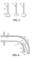
- Types of tools different 20, 21 and 22 shown in Figure 3 allow machining on the inside, undercuts or both by means of parts cut 23 chamfered on the side of the tail 24, the opposite side or both sides.
- connection 1 The software with the geometric definition of the connection 1 envisaged and that of the tools determines therefore a series of necessary machining paths to machine all the connection 1 by the selected tools.
- the next step is an audit of machining program, which is digitally simulated at using the dimensions of the selected tools.
- the verifications that are conducted are of the type of FIG. 4: the tool 25 is introduced into the blank of the fitting 1 and the side surface of its machining head 26 is active and mills the internal surface of the part tubular near the elbow.
- the program determines if it is possible to place the tool 25 so as to avoid a collision of tail 27 with the parties full of the fitting. If a collision is detected, the program seeks a suitable position of the tool 25 to allow to continue the machining, if not another tool is proposed in replacement. Internal machining fitting is more often critical but the checking relates to the machining of all surfaces.
- HSC high speed machining
- the machine tool used is numerically controlled and includes a pair of jaws 28 between which the blank of fitting to be machined is clamped. This is first of all a block 29 in the mass of which the connection will be shaped. Machining is represented here at one point intermediate, in which the form of the coupling 1 is recognizable and partially unobstructed remainder of block 29. It is recommended to work in stairs in a draft phase, that is to say mill block 29 in parallel successive passes of to form bleachers 30 by which the surface outside of fitting 1 is roughed out. The tool is guided according to the point file of the fitting model 1 obtained in the previous steps and according to the trajectory file.
- a machining finishing or half-finishing of the tube is undertaken on Parallel and intermediate lines to previous ones to get a better equalization of the surface in steps and converge to the required outer surface.
- a subsequent finishing machining can be added for get a smooth surface.
- the inside of the tube is also machined by successive passes, which include in general tangential milling. These machining operations tangential milling are also applied to the finish curved parts of the coupling, whether they are inside or outside, according to the scheme of the Figure 4.
- the connection areas to pipes 2 and 3 are repeated if necessary by specific tools to ensure the surface quality as smooth as desired.
- connection a heel remaining attached to the machine is cut to separate the connection a heel remaining attached to the machine.
- Final machining of this cord can be undertaken in another way, by example by means of a saw off the machine tool at numerical control.
- fitting 1 is fully machined, without intermediate disassembly would produce odds uncertainties. It can therefore be made with a smaller wall thickness without fear of a rupture at the pressure of the fluid. Only one copy of a series must be verified to ensure that it holds to the pressure of the fluid, since the material in which the fittings of this series are machined is controlled by the supplier for the absence of porosity, bubbles, etc. before machining. Ducts better adapted to the flow, and in particular constant section and perfectly rounded, can to be pierced. A smaller thickness of the walls, Approximately 1.5 mm instead of 2.3 to 2.6 mm required for the molding, has become possible and leads to gains in mass of about 30%.
- Another important aspect of the invention lies in the preferred choice of a large machining process speed (UGV) which reduces vibrations, improving the quality of the machining, and the efforts of side cut, allowing you to use more tools longer access to remote areas or undercut of the inner surface. This circumstance is particularly valuable for bent surfaces, where such access difficulties always appear.
- UUV machining process speed
Landscapes
- Engineering & Computer Science (AREA)
- Human Computer Interaction (AREA)
- Manufacturing & Machinery (AREA)
- Physics & Mathematics (AREA)
- General Physics & Mathematics (AREA)
- Automation & Control Theory (AREA)
- Branch Pipes, Bends, And The Like (AREA)
- Numerical Control (AREA)
- Lining Or Joining Of Plastics Or The Like (AREA)
- Moulding By Coating Moulds (AREA)
- Shaping Of Tube Ends By Bending Or Straightening (AREA)
Abstract
Description
- définition de fonctions et de contraintes, notamment dimensionnelles, du raccord ;
- élaboration d'un plan du raccord à partir desdites fonctions et contraintes ;
- vérification de fabrication possible du raccord, et révision du plan en cas de diagnostic de défaut à la vérification ;
- définition d'un programme d'usinage du raccord, comprenant une sélection d'outils, de trajectoires des outils et de paramètres de coupe par un logiciel à partir du plan ;
- simulation du programme, et révision du programme en cas de diagnostic d'erreur à la simulation ; et
- fabrication du raccord par application du programme d'usinage sur une masse serrée sur une machine-outil à commande numérique et pilotée par le programme d'usinage de façon à usiner une surface externe et une surface interne du raccord, la surface interne comportant un coude.
- la figure 1 est un raccord ;
- la figure 2 est un fragment d'un autre raccord ;
- la figure 3 illustre quelques outils ;
- la figure 4 illustre une vérification ;
- et la figure 5 représente l'usinage du raccord.
Claims (10)
- Procédé de fabrication d'un raccord de tuyau comportant des parties tubulaires, caractérisé en ce qu'il comprend les étapes suivantes :définition de fonctions et de contraintes, notamment dimensionnelles, du raccord ;élaboration d'un plan du raccord (1) à partir desdites fonctions et contraintes ;vérification de fabrication possible du raccord, et révision du plan en cas de diagnostic de défaut à la vérification ;définition d'un programme d'usinage du raccord, comprenant une sélection d'outils, de trajectoires des outils et de paramètres de coupe par un logiciel à partir du plan ;simulation du programme, et révision du programme en cas de diagnostic d'erreur à la simulation ; etfabrication du raccord par application du programme d'usinage sur un bloc (29) serré sur une machine-outil à commande numérique pilotée d'après le programme d'usinage de façon à usiner une surface externe et une surface interne du raccord, la surface interne comportant un coude.
- Procédé de fabrication d'un raccord de tuyaux d'aéronef selon la revendication 1, caractérisé en ce que la machine-outil à commande numérique est une machine à cinq axes.
- Procédé de fabrication d'un raccord de tuyaux d'aéronef selon la revendication 1 ou 2, caractérisé en ce que la fabrication comprend des ébauches de tubes par passes successives en gradins, des usinages à l'intérieur des tubes par un fraisage tangentiel, des finitions à ajustement de rayon de courbure par fraisage tangentiel, et une découpe finale du raccord par séparation dudit raccord et d'un talon du bloc, qui reste serré sur la machine-outil.
- Procédé de fabrication d'un raccord de tuyaux d'aéronef selon l'une quelconque des revendications 1 à 3, caractérisé en ce que la vérification comprend une vérification de résistance mécanique du raccord.
- Procédé de fabrication d'un raccord de tuyaux d'aéronef selon l'une quelconque des revendications 1 à 4, caractérisé en ce que la simulation comporte des vérifications de collision des outils et des queues des outils avec le raccord.
- Procédé de fabrication d'un raccord de tuyaux d'aéronef selon l'une quelconque des revendications 1 à 5, caractérisé en ce que la surface externe et la surface interne sont usinées sans démontage intermédiaire du raccord de la machine-outil.
- Procédé de fabrication d'un raccord de tuyaux d'aéronef selon l'une quelconque des revendications 1 à 6, caractérisé en ce que l'usinage est un usinage à grande vitesse (UGV).
- Raccord de tuyaux d'aéronef obtenu par un procédé conforme à l'une quelconque des revendications précédentes, caractérisé en ce qu'il est limité exclusivement par des surfaces usinées.
- Raccord de tuyaux d'aéronef selon la revendication 8, caractérisé en ce que la surface interne présente une contre-dépouille.
- Aéronef, caractérisé en ce qu'il comporte un raccord conforme à l'une quelconque des revendications précédentes.
Applications Claiming Priority (2)
| Application Number | Priority Date | Filing Date | Title |
|---|---|---|---|
| FR0350632A FR2860611B1 (fr) | 2003-10-01 | 2003-10-01 | Procede de conception et de fabrication d'un raccord de tuyaux, notamment pour aeronef. |
| FR0350632 | 2003-10-01 |
Publications (2)
| Publication Number | Publication Date |
|---|---|
| EP1521151A1 true EP1521151A1 (fr) | 2005-04-06 |
| EP1521151B1 EP1521151B1 (fr) | 2008-04-09 |
Family
ID=34307554
Family Applications (1)
| Application Number | Title | Priority Date | Filing Date |
|---|---|---|---|
| EP04104670A Expired - Lifetime EP1521151B1 (fr) | 2003-10-01 | 2004-09-24 | Procédé de conception et de fabrication d'un raccord de tuyaux, notamment pour aéronef |
Country Status (6)
| Country | Link |
|---|---|
| US (1) | US7444746B2 (fr) |
| EP (1) | EP1521151B1 (fr) |
| AT (1) | ATE391946T1 (fr) |
| CA (1) | CA2483052C (fr) |
| DE (1) | DE602004012939T2 (fr) |
| FR (1) | FR2860611B1 (fr) |
Families Citing this family (1)
| Publication number | Priority date | Publication date | Assignee | Title |
|---|---|---|---|---|
| CN113695986B (zh) * | 2021-09-02 | 2023-06-09 | 国家管网集团西南管道有限责任公司 | 弧形管道的辅助装置 |
Citations (3)
| Publication number | Priority date | Publication date | Assignee | Title |
|---|---|---|---|---|
| GB2248571A (en) * | 1990-10-09 | 1992-04-15 | Steel Castings Res | Computer controlled work treating robot |
| US5117866A (en) * | 1990-12-21 | 1992-06-02 | Pulse Electronics, Inc. | Air flow regulator for fuel measuring systems |
| US6112133A (en) * | 1998-02-27 | 2000-08-29 | Imcs, Inc. | Visual system and method for generating a CNC program for machining parts with planar and curvilinear surfaces |
Family Cites Families (2)
| Publication number | Priority date | Publication date | Assignee | Title |
|---|---|---|---|---|
| US7225050B2 (en) * | 2001-01-04 | 2007-05-29 | Sutula Jr Daniel P | Method and apparatus for precisely fitting, reproducing, and creating 3-dimensional objects from digitized and/or parametric data inputs using computer aided design and manufacturing technology |
| US6581430B2 (en) * | 2001-10-25 | 2003-06-24 | Ken Wilson | Method of making an eyewear frame |
-
2003
- 2003-10-01 FR FR0350632A patent/FR2860611B1/fr not_active Expired - Fee Related
-
2004
- 2004-09-15 US US10/940,962 patent/US7444746B2/en not_active Expired - Fee Related
- 2004-09-24 DE DE602004012939T patent/DE602004012939T2/de not_active Expired - Lifetime
- 2004-09-24 AT AT04104670T patent/ATE391946T1/de not_active IP Right Cessation
- 2004-09-24 EP EP04104670A patent/EP1521151B1/fr not_active Expired - Lifetime
- 2004-09-28 CA CA2483052A patent/CA2483052C/fr not_active Expired - Fee Related
Patent Citations (3)
| Publication number | Priority date | Publication date | Assignee | Title |
|---|---|---|---|---|
| GB2248571A (en) * | 1990-10-09 | 1992-04-15 | Steel Castings Res | Computer controlled work treating robot |
| US5117866A (en) * | 1990-12-21 | 1992-06-02 | Pulse Electronics, Inc. | Air flow regulator for fuel measuring systems |
| US6112133A (en) * | 1998-02-27 | 2000-08-29 | Imcs, Inc. | Visual system and method for generating a CNC program for machining parts with planar and curvilinear surfaces |
Non-Patent Citations (5)
| Title |
|---|
| BLOOMENTHAL M ET AL: "An approach to rapid manufacturing with custom fixturing", PROCEEDINGS OF THE 2000 IEEE INTERNATIONAL CONFERENCE ON ROBOTICS & AUTOMATION, vol. 1, 24 April 2000 (2000-04-24), San Francisco, CA, USA, pages 212 - 219, XP010500221 * |
| HANS B. KIEF: "NC/CNC Handbuch 2001/02", 2001, HANSER, MÜNCHEN, XP002274280 * |
| LIANG J ET AL: "Synthesis of consolidated data schema for engineering analysis from multiple STEP application protocols", COMPUTER AIDED DESIGN, ELSEVIER PUBLISHERS BV., BARKING, GB, vol. 31, no. 7, June 1999 (1999-06-01), pages 429 - 447, XP004172466, ISSN: 0010-4485 * |
| PARKER HANNIFIN CORPORATION - FLUID CONNECTORS GROUP: "Fluid Connectors Product Directory", 0094-B1/DE-UK-FR, March 2003 (2003-03-01), Parker Hannifin Corporation - Columbus, OH, USA, XP002274303, Retrieved from the Internet <URL:http://www.parker.com/eurofcg/Literature/Product%20Directory/english/Product%20Directory.pdf> [retrieved on 20040319] * |
| PARKER HANNIFIN CORPORATION - FLUID CONNECTORS GROUP: "Tube Fittings Products - Quick Reference Guide", BULLETIN 4300-QRG- USA, May 1997 (1997-05-01), Parker Hannifin Corporation - Columbus, OH, USA, XP002274279, Retrieved from the Internet <URL:http://www.parker.com/tfd/bulletinpdf/qrg.pdf> [retrieved on 20040319] * |
Also Published As
| Publication number | Publication date |
|---|---|
| CA2483052A1 (fr) | 2005-04-01 |
| US20050072001A1 (en) | 2005-04-07 |
| FR2860611A1 (fr) | 2005-04-08 |
| EP1521151B1 (fr) | 2008-04-09 |
| ATE391946T1 (de) | 2008-04-15 |
| FR2860611B1 (fr) | 2007-05-25 |
| DE602004012939D1 (de) | 2008-05-21 |
| US7444746B2 (en) | 2008-11-04 |
| CA2483052C (fr) | 2013-09-17 |
| DE602004012939T2 (de) | 2009-05-28 |
Similar Documents
| Publication | Publication Date | Title |
|---|---|---|
| US8549751B2 (en) | Method of manufacturing a welded component comprising a seamless bent pipe and seamless straight pipe sections | |
| JP6752214B2 (ja) | 樹脂製管継手、配管及び、配管の製造方法 | |
| US10675722B2 (en) | Method and device for centering and temporary fixation of tube parts | |
| JP2015206459A (ja) | 差込みコネクタの製造方法および差込みコネクタ | |
| CA2923490A1 (fr) | Procede de generation d'un programme d'usinage interpretable par un controleur physique d'une machine-outil a commande numerique | |
| CN102712062B (zh) | 用于制造一体式角接的方法 | |
| CN107350649A (zh) | 源自将凸缘添加到对接焊接或承插焊接端阀体铸件的焊接变形的预测算法 | |
| TW201250146A (en) | Modular fitting | |
| BR112013005061B1 (pt) | Peça de acoplamento para uma extremidade externa de um conduto multicamada, método para o acoplamento de uma extremidade externa de um conduto multicamadas a uma peça de acoplamento, e montagem de um conduto multicamadas com uma peça de acoplamento | |
| CA2838178A1 (fr) | Procede d'usinage adaptatif pour aubes de fonderie | |
| NO20200057A1 (en) | Method for manufacturing a connecting part | |
| EP1521151B1 (fr) | Procédé de conception et de fabrication d'un raccord de tuyaux, notamment pour aéronef | |
| WO2010066711A1 (fr) | Procede d'optimisation de la routage de tubes sur une structure supportant de petites deformations | |
| US7069094B2 (en) | Computer-aided product design system | |
| JP7235529B2 (ja) | 分岐継手ユニット | |
| CN106874530B (zh) | 液压成形管以及成形方法 | |
| WO2002081960A1 (fr) | Tuyau en t permettant de raccorder un tuyau d'embranchement reduit a un tuyau principal, et procede de production dudit tuyau | |
| CN115730428A (zh) | 一种相贯线切割路径计算方法 | |
| JP7303649B2 (ja) | 管継手及び配管構造 | |
| FR3142270A1 (fr) | Procédé de détermination d’un réseau de tubes dans un espace de référence d’un véhicule automobile | |
| JP6820699B2 (ja) | フランジ付き管継手 | |
| WO2017072886A1 (fr) | Élément de tuyau en résine, raccord de tuyau en résine, et procédé de fabrication de tuyau | |
| TR2023018340A2 (tr) | Segmentli̇ borularin tirnak yardimi i̇le bi̇rbi̇ri̇ne aparat i̇hti̇yaci duymadan kaynak edi̇lmesi̇ni̇ sağlamak üzere bi̇r yöntem | |
| JP2008102741A (ja) | 特注配管部品の設計方法および設計装置 | |
| EP2219125A1 (fr) | Procédé de conception d'un cadre de tube |
Legal Events
| Date | Code | Title | Description |
|---|---|---|---|
| PUAI | Public reference made under article 153(3) epc to a published international application that has entered the european phase |
Free format text: ORIGINAL CODE: 0009012 |
|
| AK | Designated contracting states |
Kind code of ref document: A1 Designated state(s): AT BE BG CH CY CZ DE DK EE ES FI FR GB GR HU IE IT LI LU MC NL PL PT RO SE SI SK TR |
|
| AX | Request for extension of the european patent |
Extension state: AL HR LT LV MK |
|
| 17P | Request for examination filed |
Effective date: 20050912 |
|
| AKX | Designation fees paid |
Designated state(s): AT BE BG CH CY CZ DE DK EE ES FI FR GB GR HU IE IT LI LU MC NL PL PT RO SE SI SK TR |
|
| 17Q | First examination report despatched |
Effective date: 20070102 |
|
| GRAP | Despatch of communication of intention to grant a patent |
Free format text: ORIGINAL CODE: EPIDOSNIGR1 |
|
| GRAS | Grant fee paid |
Free format text: ORIGINAL CODE: EPIDOSNIGR3 |
|
| GRAA | (expected) grant |
Free format text: ORIGINAL CODE: 0009210 |
|
| AK | Designated contracting states |
Kind code of ref document: B1 Designated state(s): AT BE BG CH CY CZ DE DK EE ES FI FR GB GR HU IE IT LI LU MC NL PL PT RO SE SI SK TR |
|
| REG | Reference to a national code |
Ref country code: GB Ref legal event code: FG4D Free format text: NOT ENGLISH |
|
| REG | Reference to a national code |
Ref country code: CH Ref legal event code: EP |
|
| REG | Reference to a national code |
Ref country code: IE Ref legal event code: FG4D Free format text: LANGUAGE OF EP DOCUMENT: FRENCH |
|
| REF | Corresponds to: |
Ref document number: 602004012939 Country of ref document: DE Date of ref document: 20080521 Kind code of ref document: P |
|
| REG | Reference to a national code |
Ref country code: SE Ref legal event code: TRGR |
|
| PG25 | Lapsed in a contracting state [announced via postgrant information from national office to epo] |
Ref country code: SI Free format text: LAPSE BECAUSE OF FAILURE TO SUBMIT A TRANSLATION OF THE DESCRIPTION OR TO PAY THE FEE WITHIN THE PRESCRIBED TIME-LIMIT Effective date: 20080409 |
|
| NLV1 | Nl: lapsed or annulled due to failure to fulfill the requirements of art. 29p and 29m of the patents act | ||
| PG25 | Lapsed in a contracting state [announced via postgrant information from national office to epo] |
Ref country code: BG Free format text: LAPSE BECAUSE OF FAILURE TO SUBMIT A TRANSLATION OF THE DESCRIPTION OR TO PAY THE FEE WITHIN THE PRESCRIBED TIME-LIMIT Effective date: 20080709 Ref country code: ES Free format text: LAPSE BECAUSE OF FAILURE TO SUBMIT A TRANSLATION OF THE DESCRIPTION OR TO PAY THE FEE WITHIN THE PRESCRIBED TIME-LIMIT Effective date: 20080720 Ref country code: FI Free format text: LAPSE BECAUSE OF FAILURE TO SUBMIT A TRANSLATION OF THE DESCRIPTION OR TO PAY THE FEE WITHIN THE PRESCRIBED TIME-LIMIT Effective date: 20080409 Ref country code: NL Free format text: LAPSE BECAUSE OF FAILURE TO SUBMIT A TRANSLATION OF THE DESCRIPTION OR TO PAY THE FEE WITHIN THE PRESCRIBED TIME-LIMIT Effective date: 20080409 Ref country code: PT Free format text: LAPSE BECAUSE OF FAILURE TO SUBMIT A TRANSLATION OF THE DESCRIPTION OR TO PAY THE FEE WITHIN THE PRESCRIBED TIME-LIMIT Effective date: 20080909 |
|
| PG25 | Lapsed in a contracting state [announced via postgrant information from national office to epo] |
Ref country code: PL Free format text: LAPSE BECAUSE OF FAILURE TO SUBMIT A TRANSLATION OF THE DESCRIPTION OR TO PAY THE FEE WITHIN THE PRESCRIBED TIME-LIMIT Effective date: 20080409 Ref country code: AT Free format text: LAPSE BECAUSE OF FAILURE TO SUBMIT A TRANSLATION OF THE DESCRIPTION OR TO PAY THE FEE WITHIN THE PRESCRIBED TIME-LIMIT Effective date: 20080409 |
|
| REG | Reference to a national code |
Ref country code: IE Ref legal event code: FD4D |
|
| PG25 | Lapsed in a contracting state [announced via postgrant information from national office to epo] |
Ref country code: IE Free format text: LAPSE BECAUSE OF FAILURE TO SUBMIT A TRANSLATION OF THE DESCRIPTION OR TO PAY THE FEE WITHIN THE PRESCRIBED TIME-LIMIT Effective date: 20080409 Ref country code: CZ Free format text: LAPSE BECAUSE OF FAILURE TO SUBMIT A TRANSLATION OF THE DESCRIPTION OR TO PAY THE FEE WITHIN THE PRESCRIBED TIME-LIMIT Effective date: 20080409 Ref country code: DK Free format text: LAPSE BECAUSE OF FAILURE TO SUBMIT A TRANSLATION OF THE DESCRIPTION OR TO PAY THE FEE WITHIN THE PRESCRIBED TIME-LIMIT Effective date: 20080409 |
|
| PLBE | No opposition filed within time limit |
Free format text: ORIGINAL CODE: 0009261 |
|
| STAA | Information on the status of an ep patent application or granted ep patent |
Free format text: STATUS: NO OPPOSITION FILED WITHIN TIME LIMIT |
|
| PG25 | Lapsed in a contracting state [announced via postgrant information from national office to epo] |
Ref country code: SK Free format text: LAPSE BECAUSE OF FAILURE TO SUBMIT A TRANSLATION OF THE DESCRIPTION OR TO PAY THE FEE WITHIN THE PRESCRIBED TIME-LIMIT Effective date: 20080409 Ref country code: RO Free format text: LAPSE BECAUSE OF FAILURE TO SUBMIT A TRANSLATION OF THE DESCRIPTION OR TO PAY THE FEE WITHIN THE PRESCRIBED TIME-LIMIT Effective date: 20080409 |
|
| 26N | No opposition filed |
Effective date: 20090112 |
|
| BERE | Be: lapsed |
Owner name: AIRBUS FRANCE Effective date: 20080930 |
|
| PG25 | Lapsed in a contracting state [announced via postgrant information from national office to epo] |
Ref country code: MC Free format text: LAPSE BECAUSE OF NON-PAYMENT OF DUE FEES Effective date: 20080930 Ref country code: EE Free format text: LAPSE BECAUSE OF FAILURE TO SUBMIT A TRANSLATION OF THE DESCRIPTION OR TO PAY THE FEE WITHIN THE PRESCRIBED TIME-LIMIT Effective date: 20080409 |
|
| REG | Reference to a national code |
Ref country code: CH Ref legal event code: PL |
|
| PG25 | Lapsed in a contracting state [announced via postgrant information from national office to epo] |
Ref country code: BE Free format text: LAPSE BECAUSE OF NON-PAYMENT OF DUE FEES Effective date: 20080930 |
|
| PG25 | Lapsed in a contracting state [announced via postgrant information from national office to epo] |
Ref country code: CY Free format text: LAPSE BECAUSE OF FAILURE TO SUBMIT A TRANSLATION OF THE DESCRIPTION OR TO PAY THE FEE WITHIN THE PRESCRIBED TIME-LIMIT Effective date: 20080409 |
|
| PG25 | Lapsed in a contracting state [announced via postgrant information from national office to epo] |
Ref country code: LI Free format text: LAPSE BECAUSE OF NON-PAYMENT OF DUE FEES Effective date: 20080930 Ref country code: CH Free format text: LAPSE BECAUSE OF NON-PAYMENT OF DUE FEES Effective date: 20080930 |
|
| PG25 | Lapsed in a contracting state [announced via postgrant information from national office to epo] |
Ref country code: HU Free format text: LAPSE BECAUSE OF FAILURE TO SUBMIT A TRANSLATION OF THE DESCRIPTION OR TO PAY THE FEE WITHIN THE PRESCRIBED TIME-LIMIT Effective date: 20081010 Ref country code: LU Free format text: LAPSE BECAUSE OF NON-PAYMENT OF DUE FEES Effective date: 20080924 |
|
| PG25 | Lapsed in a contracting state [announced via postgrant information from national office to epo] |
Ref country code: TR Free format text: LAPSE BECAUSE OF FAILURE TO SUBMIT A TRANSLATION OF THE DESCRIPTION OR TO PAY THE FEE WITHIN THE PRESCRIBED TIME-LIMIT Effective date: 20080409 |
|
| PG25 | Lapsed in a contracting state [announced via postgrant information from national office to epo] |
Ref country code: GR Free format text: LAPSE BECAUSE OF FAILURE TO SUBMIT A TRANSLATION OF THE DESCRIPTION OR TO PAY THE FEE WITHIN THE PRESCRIBED TIME-LIMIT Effective date: 20080710 |
|
| REG | Reference to a national code |
Ref country code: GB Ref legal event code: 732E Free format text: REGISTERED BETWEEN 20110721 AND 20110727 |
|
| REG | Reference to a national code |
Ref country code: FR Ref legal event code: CD Owner name: AIRBUS HOLDING, FR Effective date: 20110916 Ref country code: FR Ref legal event code: TP Owner name: AIRBUS HOLDING, FR Effective date: 20110913 Ref country code: FR Ref legal event code: CA Effective date: 20110916 Ref country code: FR Ref legal event code: CJ Effective date: 20110916 |
|
| REG | Reference to a national code |
Ref country code: DE Ref legal event code: R082 Ref document number: 602004012939 Country of ref document: DE Representative=s name: HENKEL, BREUER & PARTNER, DE |
|
| REG | Reference to a national code |
Ref country code: DE Ref legal event code: R082 Ref document number: 602004012939 Country of ref document: DE Representative=s name: PATENTANWAELTE HENKEL, BREUER & PARTNER, DE Effective date: 20120326 Ref country code: DE Ref legal event code: R081 Ref document number: 602004012939 Country of ref document: DE Owner name: AIRBUS OPERATIONS SAS, FR Free format text: FORMER OWNER: AIRBUS FRANCE, TOULOUSE, FR Effective date: 20120326 |
|
| PGFP | Annual fee paid to national office [announced via postgrant information from national office to epo] |
Ref country code: SE Payment date: 20120919 Year of fee payment: 9 |
|
| REG | Reference to a national code |
Ref country code: SE Ref legal event code: EUG |
|
| PG25 | Lapsed in a contracting state [announced via postgrant information from national office to epo] |
Ref country code: SE Free format text: LAPSE BECAUSE OF NON-PAYMENT OF DUE FEES Effective date: 20130925 |
|
| REG | Reference to a national code |
Ref country code: FR Ref legal event code: PLFP Year of fee payment: 13 |
|
| REG | Reference to a national code |
Ref country code: FR Ref legal event code: PLFP Year of fee payment: 14 |
|
| REG | Reference to a national code |
Ref country code: FR Ref legal event code: PLFP Year of fee payment: 15 |
|
| PGFP | Annual fee paid to national office [announced via postgrant information from national office to epo] |
Ref country code: DE Payment date: 20190918 Year of fee payment: 16 Ref country code: IT Payment date: 20190925 Year of fee payment: 16 Ref country code: FR Payment date: 20190925 Year of fee payment: 16 |
|
| PGFP | Annual fee paid to national office [announced via postgrant information from national office to epo] |
Ref country code: GB Payment date: 20190920 Year of fee payment: 16 |
|
| REG | Reference to a national code |
Ref country code: DE Ref legal event code: R119 Ref document number: 602004012939 Country of ref document: DE |
|
| GBPC | Gb: european patent ceased through non-payment of renewal fee |
Effective date: 20200924 |
|
| PG25 | Lapsed in a contracting state [announced via postgrant information from national office to epo] |
Ref country code: DE Free format text: LAPSE BECAUSE OF NON-PAYMENT OF DUE FEES Effective date: 20210401 Ref country code: FR Free format text: LAPSE BECAUSE OF NON-PAYMENT OF DUE FEES Effective date: 20200930 |
|
| PG25 | Lapsed in a contracting state [announced via postgrant information from national office to epo] |
Ref country code: GB Free format text: LAPSE BECAUSE OF NON-PAYMENT OF DUE FEES Effective date: 20200924 |
|
| PG25 | Lapsed in a contracting state [announced via postgrant information from national office to epo] |
Ref country code: IT Free format text: LAPSE BECAUSE OF NON-PAYMENT OF DUE FEES Effective date: 20200924 |