EP1521147A2 - Servo loop PID compensator with embedded rate limit - Google Patents
Servo loop PID compensator with embedded rate limit Download PDFInfo
- Publication number
- EP1521147A2 EP1521147A2 EP04104239A EP04104239A EP1521147A2 EP 1521147 A2 EP1521147 A2 EP 1521147A2 EP 04104239 A EP04104239 A EP 04104239A EP 04104239 A EP04104239 A EP 04104239A EP 1521147 A2 EP1521147 A2 EP 1521147A2
- Authority
- EP
- European Patent Office
- Prior art keywords
- block
- gain
- output
- derivative
- cutoff frequency
- Prior art date
- Legal status (The legal status is an assumption and is not a legal conclusion. Google has not performed a legal analysis and makes no representation as to the accuracy of the status listed.)
- Granted
Links
Images


Classifications
-
- G—PHYSICS
- G05—CONTROLLING; REGULATING
- G05B—CONTROL OR REGULATING SYSTEMS IN GENERAL; FUNCTIONAL ELEMENTS OF SUCH SYSTEMS; MONITORING OR TESTING ARRANGEMENTS FOR SUCH SYSTEMS OR ELEMENTS
- G05B5/00—Anti-hunting arrangements
- G05B5/01—Anti-hunting arrangements electric
-
- G—PHYSICS
- G05—CONTROLLING; REGULATING
- G05B—CONTROL OR REGULATING SYSTEMS IN GENERAL; FUNCTIONAL ELEMENTS OF SUCH SYSTEMS; MONITORING OR TESTING ARRANGEMENTS FOR SUCH SYSTEMS OR ELEMENTS
- G05B11/00—Automatic controllers
- G05B11/01—Automatic controllers electric
- G05B11/36—Automatic controllers electric with provision for obtaining particular characteristics, e.g. proportional, integral, differential
- G05B11/42—Automatic controllers electric with provision for obtaining particular characteristics, e.g. proportional, integral, differential for obtaining a characteristic which is both proportional and time-dependent, e.g. P. I., P. I. D.
Definitions
- the technical field of this invention is feedback control systems employing proportional, integral and differential compensation.
- Feedback control systems also known as servomechanisms or servo devices have been developed using a wide variety of technologies and techniques. These systems have a broad spectrum of applications. Many special types of servos are used in high performance equipment. A special type of servo loop acting to achieve proportional, integral and differential (PID) compensation is often used to processes an error signal and generate a command.
- PID proportional, integral and differential
- the goal of this loop is to generate the proper command to ultimately drive the error signal to zero.
- the command generated by the PID compensator consists of three components.
- the error is a position error.
- the task of the PID compensator is to drive the servomechanism to a commanded position, thus reducing the position error to zero.
- the design of the proper PID compensator is well-known to practitioners in the field of control systems and the details of such design approaches are not the major focus of this invention.
- Conventional design techniques assure that the design is stable with appropriate stability margins.
- Digital servos are increasingly common because they are very effective due to development in recent years.
- Figure 1 illustrates the components of a prior art PID compensator.
- the control equations are easily recognized in Figure 1.
- the input signal is position error 100.
- the output signal is torque command 110.
- the proportional signal couples position error 100 to summing junction 103.
- the integrate signal comes from integration block 101 and the modifying gain constant factor W 1 in amplifier block 102.
- the signal operation comes from derivative block 105, the modifying gain constant factor 1/W 2 in amplifier block 106, low pass filter 107 having a cutoff frequency of W 3 and low pass filter 108 having a cutoff frequency of W 4 .
- the transfer function frequency characteristics are shaped at low frequencies through parameters W 1 and W 2 and by parameters W 3 and W 4 at high frequency.
- Figure 2 illustrates a piece-wise graphical representation of the PID compensator of Figure 1 and Equation 1 with an arbitrary overall gain.
- the integral portion 200 removes low frequency offsets (DC bias) and the derivative portion 207 provides fast response to high frequency disturbances.
- the proportional portion 205 bridges the integral and derivative regions.
- Figure 2 also illustrates the derivative poles, W 3 203 and W 4 204 for the typical PID compensator illustrated in Figure 1.
- the lower frequency break points W 1 201 and W 2 202 of the transfer function versus frequency are introduced by the frequency responses of respective amplification stages 102 and 106. Since the differentiator is the dominant component at frequencies above W 2 202, the poles W 3 203 and W 4 204 can be included in the implementation without affecting the validity of the approaches to be described here.
- This invention describes a reconfigured form of the well known proportional, integral, differential (PID) servo compensator.
- the reconfiguration provides inherent limits on the rate of change of the position error without affecting the performance of the servo loop when the position error is small.
- the technique maintains the high-performance of current PID servo compensators when the position error is close to zero, the operating point of primary interest.
- Equation 2 represents mathematically the transfer functional of the block diagram of Figure 3.
- the block diagram of Figure 3 includes a computed rate command factor that can be limited and an integrator that can be limited and reset to prevent windup.
- Equating the coefficients of the PID terms in Equation 1 and Equation 2 yields three equations in three unknowns, illustrated in Equations 3.
- Solving Equation 3 for K R , K P , and K I in terms of W 1 and W 2 can yield complex numbers. This form is thus not always realizable in hardware.
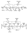
- Figure 4 illustrates such an embodiment of the servo compensator. This is similar to the servo compensator of Figure 3 with changes to the path for the computed rate and an additional proportional path with limit to the output.
- Figure 4 also includes slight changes in the gain blocks.
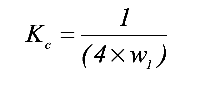
- the gain after the last summing junction K C normalizes the compensator gain to match the gain of the original compensator of Figure 3.
- Equation 4 shows the transfer function for the compensator of Figure 4. The limit blocks are ignored for now.
- the differentiator poles, W 3 203 and W 4 204, are omitted from Figure 4 though these differentiator poles must be included in the final implementation. Equating the coefficients as before yields three equations with four unknowns:
- K C can be selected such that the quadratic term of Equation 6 is zero, guaranteeing a single real value for K I .
- the results of the four equations are shown in Equation 7. These coefficients yield the same closed loop results as the original form of Equation 1.
- the rate limit can be applied. Note that the commanded rate goes to two different limit blocks 406 and 411. When the position error is large and the measured rate equals the desired rate in steady state operation (constant slew rate), a constant output that counteracts friction or any torque offsets such as gravity or springs is desirable. Of course the output is not truly constant, since the spring torque may change as the actuator moves but that is why the loop is closed. This constant output should come from the integrator. By setting rate_limit_2 to the desired rate, the integrator input becomes zero. Thus the integrator output is instantaneously constant. Setting rate_limit_1 equal to the desired rate times K D , the other paths contribute nothing to the output in this particular steady state condition.
- the integral term remains on the original curve 500 for small error but shifts to 511 when the position error exceeds rate_limit_2 and shift to curve 512 when the position error exceeds rate_limit_1.
- Figure 5 illustrates curves 500, 511 and 512 separately whereas they actually represent three distinct operating points.
- the integral portion of the response transitions smoothly from curve 500 to the left as the position error increases. For example, when position error equals rate_limit_2, curves 500 and 511 are identical.
- the two derivative low pass filters with respective cut off frequencies of W 3 and W 4 are provided in the derivative path following derivative block 401 in a manner similar to that illustrated in Figure 1.
- This invention is usable in any servo that meets the criteria of high bandwidth, fast actuator and required rate limit during moves.
Landscapes
- Physics & Mathematics (AREA)
- General Physics & Mathematics (AREA)
- Engineering & Computer Science (AREA)
- Automation & Control Theory (AREA)
- Control Of Position Or Direction (AREA)
- Feedback Control In General (AREA)
- Control Of Electric Motors In General (AREA)
Abstract
Description


Claims (12)
- A servomechanism having proportional, integral, and differential control (PID) receiving an error signal and generating a command signal comprising:a first gain block having an input receiving the error signal, an output and a first gain;a first rate-limiter block having an input connected to said output of said first gain block, an output and a first rate limit;a derivative block having an input receiving the error signal and an output;a first summer-block having a first input connected to said output of said first rate-limiter block and a second input connected to said output of said derivative block and a first sum output;a second rate-limiter block having an input connected to said output of said first gain block, and output and a second rate limit less than said first rate limit;an integrator block having an input connected to said first sum output of said first summer-block and an output;a second gain block having an input connected to said output of said integrator block, an output and a second gain;a third gain block having an input connected to said output of said derivative block, an output and a third gain; andsecond summer-block having a first input connected to said output of said second gain block, a second input connected to said output of said third gain block, a third input connected to said output of said second rate-limiter block, and a second sum output, said second sum output being said command signal.
- The servomechanism of claim 1, further including:a fourth gain block having an input connected to said second sum output of said second summer-block, an output being said command signal and a fourth gain.
- The servomechanism of either claim 1 or claim 2, further including:at least one low-pass filter connected between said output of said derivative block and said input of said first summer-block and said input of said third gain block.
- The servomechanism of claim 3, wherein:said at least one low-pass filter includesa first low-pass filter having an input connected to said output of said derivative block, an output and s first cutoff frequency, anda second low-pass filter block having an input connected to said output of said first low-pass filter, and output and a second cutoff frequency higher than said first cutoff frequency.
- The servomechanism of claim 4, wherein:said first cutoff frequency and said second cutoff frequency are both higher than an effective cutoff frequency of said integrator block and an effective cutoff frequency of said derivative block.
- The servomechanism of claim 5, wherein:where W1 is said effective cutoff frequency of said integrator block and W2 is said effective cutoff frequency of said derivative block.said first gain KR, said second gain KI, said third gain KD and said fourth gain KC are set whereby


- A method of servo control receiving an error signal and generating a command signal comprising the steps of:amplifying the error signal by a first gain;limiting the amplified error signal by a first rate limit;forming a derivative of the error signal;summing the a first rate limited amplified error signal and the derivative of the error signal thereby forming a first sum signal;limiting the amplified error signal by block second rate limit, the second rate limit less than the first rate limit;integrating block the first sum signal;amplifying the derivative of the error signal by a second gain;amplifying the integrated first sum signal by a third gain; andsumming amplified first sum signal, the amplified derivative signal and the second rate limited error signal thereby forming a second sum signal being said command signal.
- The method of claim 7, further including:amplifying the second sum signal by a fourth gain.
- The method of either claim 7 or claim 8, further including:low-pass filtering the derivative signal.
- The method of claim 9 wherein:said step of low-pass filtering the derivative signal includes:a first low-pass filtering having a first cutoff frequency, anda second low-pass filtering having a second cutoff frequency higher than said first cutoff frequency.
- The method of claim 10, wherein:said first cutoff frequency and said second cutoff frequency are both higher than an effective cutoff frequency of said integrator block and an effective cutoff frequency of said derivative block.
- The method of claim 11, wherein:where W1 is said effective cutoff frequency of said integrator block and W2 is said effective cutoff frequency of said derivative block.said first gain KR, said second gain KI, said third gain KD and said fourth gain KC are set whereby

Applications Claiming Priority (2)
| Application Number | Priority Date | Filing Date | Title |
|---|---|---|---|
| US10/672,681 US6870345B1 (en) | 2003-09-26 | 2003-09-26 | Servo loop PID compensator with embedded rate limit |
| US672681 | 2003-09-26 |
Publications (3)
| Publication Number | Publication Date |
|---|---|
| EP1521147A2 true EP1521147A2 (en) | 2005-04-06 |
| EP1521147A3 EP1521147A3 (en) | 2005-04-27 |
| EP1521147B1 EP1521147B1 (en) | 2007-06-06 |
Family
ID=34274779
Family Applications (1)
| Application Number | Title | Priority Date | Filing Date |
|---|---|---|---|
| EP04104239A Expired - Lifetime EP1521147B1 (en) | 2003-09-26 | 2004-09-02 | Servo loop PID compensator with embedded rate limit |
Country Status (4)
| Country | Link |
|---|---|
| US (1) | US6870345B1 (en) |
| EP (1) | EP1521147B1 (en) |
| JP (1) | JP2005108228A (en) |
| DE (1) | DE602004006814T2 (en) |
Families Citing this family (5)
| Publication number | Priority date | Publication date | Assignee | Title |
|---|---|---|---|---|
| US8800697B2 (en) | 2009-09-01 | 2014-08-12 | Ryno Motors, Inc. | Electric-powered self-balancing unicycle with steering linkage between handlebars and wheel forks |
| US8756039B2 (en) * | 2010-03-02 | 2014-06-17 | Fisher-Rosemount Systems, Inc. | Rapid process model identification and generation |
| US9085334B2 (en) | 2012-08-22 | 2015-07-21 | Ryno Motors, Inc. | Electric-powered self-balancing unicycle |
| US10146190B2 (en) * | 2016-04-28 | 2018-12-04 | Dell Products L.P. | Systems and methods for providing controller response stability in a closed-loop system |
| JP6877729B2 (en) * | 2016-11-10 | 2021-05-26 | 中村留精密工業株式会社 | Parameter adjustment system for servo motor control device in machine tools |
Family Cites Families (17)
| Publication number | Priority date | Publication date | Assignee | Title |
|---|---|---|---|---|
| US3723842A (en) * | 1972-03-09 | 1973-03-27 | Collins Radio Co | Digital servo motor control with an error rate derivative circuit |
| NL178539C (en) * | 1979-10-19 | 1986-04-01 | Ihc Holland Nv | REGULATION SYSTEM. |
| DE3226283A1 (en) * | 1982-07-14 | 1984-01-19 | Vdo Adolf Schindling Ag, 6000 Frankfurt | IDLE CONTROLLER, IN PARTICULAR FOR MOTOR VEHICLES |
| US5134354A (en) * | 1989-04-10 | 1992-07-28 | Kabushiki Kaisha Yaskawa Denki Seisakusho | Servo motor control apparatus |
| JPH02297602A (en) * | 1989-05-12 | 1990-12-10 | Fanuc Ltd | Sliding mode control system including nonlinear item compensation |
| JP2531796B2 (en) * | 1989-07-07 | 1996-09-04 | 株式会社東芝 | Adjuster |
| US5184055A (en) * | 1989-10-06 | 1993-02-02 | Canon Kabushiki Kaisha | Device for positioning control |
| US5189620A (en) * | 1989-10-06 | 1993-02-23 | United Technologies Corporation | Control system for gas turbine helicopter engines and the like |
| US5764017A (en) * | 1996-04-16 | 1998-06-09 | Iomega Corporation | Servo loop compensation technique exhibiting improved bandwith |
| KR940003005B1 (en) * | 1991-01-26 | 1994-04-09 | 삼성전자 주식회사 | Speed Control Method of Synchronous AC Servo Motor |
| DE19516239C2 (en) * | 1995-05-03 | 2001-07-19 | Siemens Ag | Method for parameterizing a linear lambda controller for an internal combustion engine |
| US5614801A (en) * | 1995-07-10 | 1997-03-25 | Allen-Bradley Company, Inc. | Apparatus for effectively handling a saturation condition in a digital compensator |
| US5714831A (en) * | 1995-11-13 | 1998-02-03 | Wisconsin Alumni Research Foundation | Method and apparatus for improved control of piezoelectric positioners |
| JP2962683B2 (en) * | 1996-12-04 | 1999-10-12 | 本田技研工業株式会社 | Electric power steering device |
| US6178370B1 (en) * | 1998-02-12 | 2001-01-23 | The B. F. Goodrich Company | Deceleration based antiskid brake contoller with adaptive deceleration threshold |
| IL127370A (en) * | 1998-12-02 | 2004-05-12 | Yaskawa Eshed Technology Ltd | Servomechanism control system and method |
| US6285115B1 (en) * | 2000-05-22 | 2001-09-04 | Caterpillar Inc. | Method and apparatus for controlling position and velocity of a piezoelectric device |
-
2003
- 2003-09-26 US US10/672,681 patent/US6870345B1/en not_active Expired - Lifetime
-
2004
- 2004-09-02 DE DE602004006814T patent/DE602004006814T2/en not_active Expired - Lifetime
- 2004-09-02 EP EP04104239A patent/EP1521147B1/en not_active Expired - Lifetime
- 2004-09-24 JP JP2004276932A patent/JP2005108228A/en not_active Abandoned
Also Published As
| Publication number | Publication date |
|---|---|
| US6870345B1 (en) | 2005-03-22 |
| EP1521147B1 (en) | 2007-06-06 |
| JP2005108228A (en) | 2005-04-21 |
| DE602004006814D1 (en) | 2007-07-19 |
| EP1521147A3 (en) | 2005-04-27 |
| US20050067997A1 (en) | 2005-03-31 |
| DE602004006814T2 (en) | 2008-02-07 |
Similar Documents
| Publication | Publication Date | Title |
|---|---|---|
| Boerlage et al. | Model-based feedforward for motion systems | |
| US8170408B2 (en) | Optical image stabilization in a digital still camera or handset | |
| KR900005546B1 (en) | Adaptive Process Control | |
| EP0320471B1 (en) | Common mode sensing and control in balanced amplifier chains | |
| Ellis et al. | Cures for low-frequency mechanical resonance in industrial servo systems | |
| EP1521147B1 (en) | Servo loop PID compensator with embedded rate limit | |
| US7414379B2 (en) | Servo control system | |
| HosseinNia et al. | Fractional-order precision motion control for mechatronic applications | |
| Kempf et al. | Discrete-time disturbance observer design for systems with time delay | |
| US7928800B2 (en) | Programmable compensation network for operational amplifiers | |
| US20040054440A1 (en) | Feedback control device | |
| US4958114A (en) | Feedback controller | |
| JPH086603A (en) | Servo system adjusting method and servo control device thereof | |
| RU2156992C1 (en) | Proportional-integral-derivative regulator with clipped output signals | |
| RU2120654C1 (en) | Pid control regulator with constrained output signals | |
| JP2650822B2 (en) | Control device | |
| JPH05150802A (en) | Deviation variable and deviation hysteresis type PI control method | |
| US20260019017A1 (en) | Controller circuit for motor | |
| Vrančić et al. | Improving PID controller disturbance rejection by means of magnitude optimum | |
| US20050065621A1 (en) | Methods of designing optimal linear controllers | |
| CN112859587B (en) | PID target tracking control method based on additional integrated module | |
| JPH0378802A (en) | Sliding mode control method | |
| KR20210103163A (en) | Position controlling apparatus for motor | |
| JPH06250740A (en) | Digital positioning controller | |
| US6943626B2 (en) | Wideband precision fixed-gain amplifier architecture, apparatus, and method |
Legal Events
| Date | Code | Title | Description |
|---|---|---|---|
| PUAI | Public reference made under article 153(3) epc to a published international application that has entered the european phase |
Free format text: ORIGINAL CODE: 0009012 |
|
| PUAL | Search report despatched |
Free format text: ORIGINAL CODE: 0009013 |
|
| AK | Designated contracting states |
Kind code of ref document: A2 Designated state(s): AT BE BG CH CY CZ DE DK EE ES FI FR GB GR HU IE IT LI LU MC NL PL PT RO SE SI SK TR |
|
| AX | Request for extension of the european patent |
Extension state: AL HR LT LV MK |
|
| AK | Designated contracting states |
Kind code of ref document: A3 Designated state(s): AT BE BG CH CY CZ DE DK EE ES FI FR GB GR HU IE IT LI LU MC NL PL PT RO SE SI SK TR |
|
| AX | Request for extension of the european patent |
Extension state: AL HR LT LV MK |
|
| 17P | Request for examination filed |
Effective date: 20051027 |
|
| AKX | Designation fees paid |
Designated state(s): DE FR GB |
|
| GRAP | Despatch of communication of intention to grant a patent |
Free format text: ORIGINAL CODE: EPIDOSNIGR1 |
|
| GRAS | Grant fee paid |
Free format text: ORIGINAL CODE: EPIDOSNIGR3 |
|
| GRAA | (expected) grant |
Free format text: ORIGINAL CODE: 0009210 |
|
| AK | Designated contracting states |
Kind code of ref document: B1 Designated state(s): DE FR GB |
|
| REG | Reference to a national code |
Ref country code: GB Ref legal event code: FG4D |
|
| REF | Corresponds to: |
Ref document number: 602004006814 Country of ref document: DE Date of ref document: 20070719 Kind code of ref document: P |
|
| ET | Fr: translation filed | ||
| PLBE | No opposition filed within time limit |
Free format text: ORIGINAL CODE: 0009261 |
|
| STAA | Information on the status of an ep patent application or granted ep patent |
Free format text: STATUS: NO OPPOSITION FILED WITHIN TIME LIMIT |
|
| 26N | No opposition filed |
Effective date: 20080307 |
|
| REG | Reference to a national code |
Ref country code: FR Ref legal event code: PLFP Year of fee payment: 13 |
|
| REG | Reference to a national code |
Ref country code: FR Ref legal event code: PLFP Year of fee payment: 14 |
|
| REG | Reference to a national code |
Ref country code: FR Ref legal event code: PLFP Year of fee payment: 15 |
|
| PGFP | Annual fee paid to national office [announced via postgrant information from national office to epo] |
Ref country code: DE Payment date: 20190813 Year of fee payment: 16 Ref country code: FR Payment date: 20190819 Year of fee payment: 16 |
|
| PGFP | Annual fee paid to national office [announced via postgrant information from national office to epo] |
Ref country code: GB Payment date: 20190827 Year of fee payment: 16 |
|
| REG | Reference to a national code |
Ref country code: DE Ref legal event code: R119 Ref document number: 602004006814 Country of ref document: DE |
|
| GBPC | Gb: european patent ceased through non-payment of renewal fee |
Effective date: 20200902 |
|
| PG25 | Lapsed in a contracting state [announced via postgrant information from national office to epo] |
Ref country code: DE Free format text: LAPSE BECAUSE OF NON-PAYMENT OF DUE FEES Effective date: 20210401 Ref country code: FR Free format text: LAPSE BECAUSE OF NON-PAYMENT OF DUE FEES Effective date: 20200930 |
|
| PG25 | Lapsed in a contracting state [announced via postgrant information from national office to epo] |
Ref country code: GB Free format text: LAPSE BECAUSE OF NON-PAYMENT OF DUE FEES Effective date: 20200902 |