EP1521042A1 - Outdoor unit of air conditioner - Google Patents
Outdoor unit of air conditioner Download PDFInfo
- Publication number
- EP1521042A1 EP1521042A1 EP03738561A EP03738561A EP1521042A1 EP 1521042 A1 EP1521042 A1 EP 1521042A1 EP 03738561 A EP03738561 A EP 03738561A EP 03738561 A EP03738561 A EP 03738561A EP 1521042 A1 EP1521042 A1 EP 1521042A1
- Authority
- EP
- European Patent Office
- Prior art keywords
- case
- foundation
- outdoor unit
- supports
- parts
- Prior art date
- Legal status (The legal status is an assumption and is not a legal conclusion. Google has not performed a legal analysis and makes no representation as to the accuracy of the status listed.)
- Granted
Links
Images


Classifications
-
- F—MECHANICAL ENGINEERING; LIGHTING; HEATING; WEAPONS; BLASTING
- F24—HEATING; RANGES; VENTILATING
- F24F—AIR-CONDITIONING; AIR-HUMIDIFICATION; VENTILATION; USE OF AIR CURRENTS FOR SCREENING
- F24F5/00—Air-conditioning systems or apparatus not covered by F24F1/00 or F24F3/00, e.g. using solar heat or combined with household units such as an oven or water heater
-
- F—MECHANICAL ENGINEERING; LIGHTING; HEATING; WEAPONS; BLASTING
- F24—HEATING; RANGES; VENTILATING
- F24F—AIR-CONDITIONING; AIR-HUMIDIFICATION; VENTILATION; USE OF AIR CURRENTS FOR SCREENING
- F24F1/00—Room units for air-conditioning, e.g. separate or self-contained units or units receiving primary air from a central station
- F24F1/06—Separate outdoor units, e.g. outdoor unit to be linked to a separate room comprising a compressor and a heat exchanger
- F24F1/60—Arrangement or mounting of the outdoor unit
-
- F—MECHANICAL ENGINEERING; LIGHTING; HEATING; WEAPONS; BLASTING
- F24—HEATING; RANGES; VENTILATING
- F24F—AIR-CONDITIONING; AIR-HUMIDIFICATION; VENTILATION; USE OF AIR CURRENTS FOR SCREENING
- F24F1/00—Room units for air-conditioning, e.g. separate or self-contained units or units receiving primary air from a central station
- F24F1/06—Separate outdoor units, e.g. outdoor unit to be linked to a separate room comprising a compressor and a heat exchanger
- F24F1/46—Component arrangements in separate outdoor units
- F24F1/48—Component arrangements in separate outdoor units characterised by air airflow, e.g. inlet or outlet airflow
- F24F1/50—Component arrangements in separate outdoor units characterised by air airflow, e.g. inlet or outlet airflow with outlet air in upward direction
-
- F—MECHANICAL ENGINEERING; LIGHTING; HEATING; WEAPONS; BLASTING
- F24—HEATING; RANGES; VENTILATING
- F24F—AIR-CONDITIONING; AIR-HUMIDIFICATION; VENTILATION; USE OF AIR CURRENTS FOR SCREENING
- F24F1/00—Room units for air-conditioning, e.g. separate or self-contained units or units receiving primary air from a central station
- F24F1/06—Separate outdoor units, e.g. outdoor unit to be linked to a separate room comprising a compressor and a heat exchanger
- F24F1/56—Casing or covers of separate outdoor units, e.g. fan guards
Definitions
- the present invention relates to an air conditioner outdoor unit, and more particularly relates to an air conditioner outdoor unit having a plurality of foundation legs for fixing such.
- an air conditioner there is known a so-called multi-type air conditioner for buildings wherein a plurality of indoor units are connected to one outdoor unit.
- the outdoor unit is generally installed on the roof of the building, and temperature-controlled air is supplied from this outdoor unit to an indoor unit provided in each room of the building.
- the outdoor unit in a conventional air conditioner has a rectangular parallelepiped-shaped case, a heat exchanger is provided at the upper part inside the case, and a compressor and other constituent parts are provided at the lower part inside the case. Further, a fan and a motor for driving this fan are provided at the upper surface of the case.
- such an outdoor unit is installed on the roof of a building, and the like; for installation purposes, a plurality of flange-shaped foundation legs that protrude outward are installed at the bottom part of the case. Further, by fixing these foundation legs to a concrete part of the building by chemical anchors and the like, the entire outdoor unit is fixed (e.g., refer to Japanese Patent Application Kokai No. H10-132407).
- a plurality of foundation legs is provided at the bottom part of the case so that they protrude outward, as discussed earlier. Because these foundation legs protrude further outward from the outer perimeter of the case, there are cases in which the outdoor unit easily contacts other members during transport, and impacts the ground and the like when dropped. Accordingly, the foundation legs in a conventional apparatus require strength above the strength needed for normal fixing, and are usually made of a relatively thick steel plate. This consequently hinders reducing costs. This situation applies not only to multi-type outdoor units for buildings, but also for outdoor units used in air conditioners for homes.
- the air conditioner outdoor unit according to Claim 1 comprises an outdoor refrigerant circuit that includes a compressor, pipes, and a heat exchanger; a case that houses the refrigerant circuit; and a plurality of supports provided so that they protrude downward from the bottom part of the case. Further, foundation legs are provided at the lower ends of the plurality of supports for fixing such, so that they extend toward the inner side of the case.
- the outdoor unit is installed by fixing a foundation leg provided at the lower end of a plurality of supports to a member on the fixed side.
- the foundation legs are fixed to a concrete part on the roof of the building by chemical anchors and the like, and the entire unit is thereby fixed.
- the foundation leg is formed into, for example, a flange shape, the same as conventionally; however, because it is provided at the lower end part of the support so that it extends toward the inner side of the case, in cases such as if colliding with members on the opposite side or if being dropped during transport or installation of the outdoor unit, the support positioned more on the outside than the foundation leg contacts the opposite member or the ground first.
- the foundation leg is protected by the support and the like; accordingly, the foundation leg can be made of a thinner plate than conventionally, and costs can be reduced.
- the air conditioner outdoor unit according to Claim 2 is the outdoor unit as recited in Claim 1, wherein the plurality of supports are provided extending in the vertical direction at a plurality of locations on the peripheral part of the case; and the plurality of foundation legs are formed by bending a portion of the lower end part of each of the supports.
- the foundation legs are formed by bending a portion of the lower end part of each support, i.e., as an integrated unit with the support. Consequently, it can be constructed at a lower cost compared to the case in which a separate member is fixed to the support by welding and the like.
- the air conditioner outdoor unit according to Claim 3 is the outdoor unit as recited in Claim 1 or Claim 2, wherein the case has a rectangular cross section; and the plurality of supports are provided at the four corners of the case, and foundation legs, which are provided on two supports each provided along one prescribed side of the case, are provided extending so that they mutually oppose and mutually approach one another.
- the foundation legs of two supports provided along one side of the case extend so that they mutually oppose and approach one another. Accordingly, the work of fixing two of the four foundation legs can be performed if positioned facing one side surface of the case; ultimately, the work of fixing all four of the foundation legs can be performed from two locations.
- the air conditioner outdoor unit according to Claim 4 comprises: a case having a plurality of vertical strength parts extending substantially vertically, and that houses an outdoor refrigerant circuit that includes a compressor, pipes, and a heat exchanger; and a plurality of foundation fixed parts provided below the case to fix the case to the installation location.
- the vertical strength parts extend downward to the height position of the surface wherein the foundation fixed parts are fixed to the installation location.
- the region formed by the linking of the plurality of foundation fixed parts is included, viewed in a plan view, in the region formed by linking the outer parts of the lower ends of the plurality of vertical strength parts.
- the present outdoor unit is installed by fixing to a foundation surface of the installation location a plurality of foundation fixed parts provided below the case.
- the foundation fixed parts are fixed to a concrete part on a roof of a building and the like by anchors and the like, and the entire unit is thereby fixed.
- the plurality of foundation fixed parts are provided so that the region formed by linking the plurality of foundation fixed parts is included, viewed in a plan view, in the region formed by linking the outer parts of the lower ends of the plurality of vertical strength parts; consequently, in cases such as if colliding with the foundation surface and the like or if being dropped during transport or during installation of the outdoor unit, the vertical strength part positioned more on the outside than the foundation fixed part contacts the foundation surface or the ground first.
- the foundation fixed part is protected by the vertical strength part; accordingly, the foundation fixed part can be made of a thinner plate than conventionally, and costs can be reduced.
- the air conditioner outdoor unit according to Claim 5 is the outdoor unit as recited in Claim 4, wherein the foundation fixed parts are fixed to the bottom part of the case.
- the positions at which the foundation fixed parts are provided are variously selectable.
- the air conditioner outdoor unit according to Claim 6 is the outdoor unit as recited in Claim 4 or Claim 5, wherein the plurality of foundation fixed parts arranged between the vertical strength parts are formed as an integrated member.
- the number of parts can be reduced.
- FIG. 1 is an external perspective view of the outdoor unit according to the first embodiment of the present invention.
- FIG. 2 is a schematic plan view that depicts the positional relationship of each of the foundation legs of the outdoor unit of the first embodiment.
- FIG. 3 is an external partial view that depicts an aspect when the outdoor unit of the first embodiment has been dropped.
- FIG. 4 is an external perspective view of the outdoor unit according to the second embodiment of the present invention.
- FIG. 5 is a cross-sectional view taken along the B-B line in FIG. 4, and depicts the arrangement of the bottom plate, supports, and foundation legs from a side view.
- FIG. 6 is a cross-sectional view taken along the C-C line in FIG. 4, and depicts the arrangement of the supports and the foundation legs in a plan view.
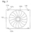
- FIG. 7 is an auxiliary view taken from the D arrow in FIG. 4.
- FIG. 1 depicts an air conditioner outdoor unit 1 according to the first embodiment of the present invention.
- This outdoor unit 1 is used in a multi-type air conditioning system for a building, and is generally constituted so that it is installed on the roof of the building.
- external pipes and the like are omitted from FIG. 1.
- the outdoor unit 1 has a case 2 that is substantially a rectangular parallelepiped, and an outdoor refrigerant circuit 3 housed inside the case 2.
- the case 2 is substantially rectangular parallelepiped-shaped, as discussed earlier. Its cross section is rectangular shaped and it is provided with four supports 5a, 5b, 5c, 5d arranged at the four corners, left-right ventilation parts (openings) 6, 7, respectively capable of air inflow, a front plate 8, a rear plate 9, a top plate 10, and a bottom plate 11.
- each support 5a - 5d each comprise a quadrilateral pipe-shaped member, and the upper end of each support 5a - 5d is fixed to the top plate 10.
- each support 5a - 5d extends so that it protrudes further downward from the bottom plate 11 of the case 2; accordingly, it is constituted so that a space is formed below the bottom plate 11 when installing the outdoor unit 1.
- the lower end of each support 5a - 5d is provided a rectangular-shaped foundation leg 12a, 12b, 12c, 12d (the foundation leg 12d is not shown in FIG. 1), which are formed by bending a portion thereof toward the inside of the case.
- the foundation legs 12b, 12c of the two supports 5b, 5c provided along the front plate 8 are formed extending so that they mutually oppose and mutually approach one another; in addition, the foundation legs 12a, 12d of the other supports 5a, 5d are likewise formed extending so that they mutually oppose and mutually approach one another. Furthermore, a through hole is formed in each of the foundation legs 12a -12d, through which a chemical anchor for fixing passes through.
- the left-right ventilation parts 6, 7 are openings capable of air inflow from the outside toward the inside of the case 2, and transverse grilles 13, 14 are mounted on the outside thereof.
- the front plate 8 comprises a front plate upper part 8a, arranged on the upper part, and a front plate lower part 8b arranged on the lower part.
- the front plate upper part 8a is fixed to the outer side of the supports 5b, 5c.
- the front plate lower part 8b is fixed to the inner side of the two supports 5b, 5c, and the upper part is linked to the front plate upper part 8a, but is inclined so that it goes more to the inner side (rear side) of the case 2 as it goes downward from the upper end part.
- the rear plate 9 is constituted substantially the same as the front plate 8, though the rear plate 9 is not clearly shown in the drawing.
- the rear plate 9 comprises a rear plate upper part, which is formed at a position the same height as the front plate upper part 8a, and a rear plate lower part, which is formed at a position the same height as the front plate lower part 8b, and the rear plate lower part is inclined so that it goes more to the inner side (front side) of the case 2 as it goes downward.
- an opening is formed in the major part of the rear plate upper part, and is capable of an air inflow from the outside.
- a tubular bell mouth 15 is provided so that it covers this opening. Furthermore, a fan 16 is provided freely rotatable inside this bell mouth 15, and this fan 16 is constituted so that it is rotatably driven by a fan motor 17 arranged therebelow. Furthermore, the fan motor 17 is supported in the case 2 by a support frame, (not shown). In addition, a fan grille 18 is mounted at the upper opening of the bell mouth 15.
- the case 2 constituted in this manner comprises an upper case part 2a formed by the front plate upper part 8a of the front plate 8, the rear plate upper part of the rear plate 9, and the portions of the ventilation parts 6, 7 that are arranged at a position the same height as the front plate upper part 8a.
- a lower case part 2b is formed by the front plate lower part 8b of the front plate 8, the rear plate lower part of the rear plate 9, and the portions of the ventilation parts 6, 7 that are arranged at a position the same height as the front plate lower part 8b.
- the projected area of the lower case part 2b is comparatively smaller than the upper case part 2a, viewed from a plan view, excluding the boundary portion with the upper case part 2a.
- the refrigerant circuit 3 principally has a heat exchanger 20, which is arranged at the upper part of the inside of the case 2; a compressor 21, which is fixed on the bottom plate 11 of the case 2; and various pipes linking these.
- the heat exchanger 20 is formed in a "U" shape viewed from a plan view, and is arranged along the left-right ventilation parts 6, 7 and the rear plate 9 of the case 2.
- the heat exchanger 20 exchanges heat between the air that flows in from the outside and the refrigerant.
- the heat exchanger 20 is arranged at a height position corresponding to the front plate upper part 8a and the rear plate upper part, i.e., so that it is housed in the upper case part 2a.
- the compressor 21 is arranged at a height position corresponding to the front plate lower part 8b and the rear plate lower part, i.e., so that it is housed in the lower case part 2b.
- the plates of the foundation legs were made of a sufficient thickness to ensure strength so that they would not deform even when struck.
- the support 5b hits the ground first, as shown in FIG. 3, thus preventing the foundation leg 12b from directly hitting the ground.
- the foundation leg is protected by this support. Consequently, it is preferable to ensure the strength of the foundation leg during fixing, the plate can be made thinner compared with a conventional foundation leg, and the cost can be reduced.
- the heat exchanger efficiency depends greatly upon the heat exchanger surface area of the heat exchanger; however, in the present embodiment, the upper case part 2a, i.e., the space of the portion in which the heat exchanger 20 is housed, is comparatively the same space as in a conventional apparatus, and there is no change in the heat exchanger surface area of the heat exchanger 20. Accordingly, the heat exchanger efficiency does not suffer. Moreover, because the dead space of the lower case part 2b where the heat exchanger 20 is originally not arranged is eliminated, and the work space for fixing the foundation legs is secured, the installation work efficiency can be made satisfactory without causing a loss in the heat exchanger efficiency.
- FIG. 4 depicts an air conditioner outdoor unit 101 according to the second embodiment of the present invention.
- the outdoor unit 101 comprises a multi-type air conditioner, is installed on the roof of a building, and the like, and is connected to a plurality of indoor units via communicating pipes.
- the outdoor unit 101 is a type that sucks in air from the side surface, exchanges heat, and then blows out air from the top surface, and is provided with a case 112, an outdoor refrigerant circuit 113 housed inside the case 112, and a ventilating fan 114 provided in the upper part of the case 112.
- the case 112 is substantially a rectangular parallelepiped, and principally comprises supports 121a - 121d respectively arranged at the four corners, a top plate 122, a front plate 123, a rear plate 124, a pair of side plates 125, and a bottom plate 126.
- the supports 121a - 121d are columnar members that extend vertically from the upper end to the lower end of each corner of the case 112, and fix and support the top plate 122, the front plate 123, the rear plate 124, the pair of side plates 125, and the bottom plate 126.
- the top plate 122 has an air outlet 122a comprising an opening provided in the center thereof, and a fan grille 122b is provided so that it covers the upper part of the opening. Furthermore, it is constituted so that the air sucked into the case 112 blows out upward from the air outlet 122a.
- the front plate 123 in the present embodiment comprises the upper front plate 123a arranged on the lower side of the top plate 122, a middle front plate 123b arranged on the lower side of the upper front plate 123a, and a lower front plate 123c arranged on the lower side of the middle front plate 123b.
- the front plate 123 has a structure with three partitions: upper, middle, and lower.
- the rear plate 124 has an air inlet 124a for taking air into the case 112.
- the air inlet 124a comprises an opening provided substantially over the entire surface, the details of which are not shown.
- Each side plate 125, in a pair of side plates 125, has an air inlet 125a for taking air into the case 112.
- each air inlet 125a comprises an opening provided in the surface, excluding the vicinity of the front plate 123. Air is thus taken into the case 112 by these air inlets 124a, 125a.
- the bottom plate 126 supports and fixes the equipment at various pipes that constitute the outdoor refrigerant circuit 113.
- the bottom plate 126 is supported by the four supports 121a - 121d so that a space is created between the bottom plate 126 and the installation surface of the installation location.
- foundation legs 127a, 127b are provided below the case 112 for fixing the case 112 to the installation location.
- FIG. 5 is a cross-sectional view taken along the B-B line in FIG. 4, and depicts the arrangement of the bottom plate 126, the supports 121c, 121d, and the foundation legs 127a, 127b, seen from a side view.
- FIG. 6 is a cross-sectional view taken along the C-C line in FIG. 4, and depicts the arrangement, seen from a planar view, of the supports 121a - 121d and the foundation legs 127a, 127b.
- FIG. 7 is an auxiliary view taken along the D arrow in FIG. 4.
- the foundation legs 127a, 127b are U-shaped members that are fixed to the front plate 123 side and the rear plate 124 side of the lower surface of the bottom plate 126.
- the foundation legs 127a, 127b comprise a plate-shaped bottom plate fixed part 127c, which is fixed to the lower surface of the bottom plate 126; a plate-shaped vertical part 127d that extends downward from the end part of the bottom plate fixed part 127c on the inner side of the case 112; and a plate-shaped mounting part 127e that extends from the lower end of the vertical part 127d toward the outer side of the case 112.
- the mounting part 127e is connected to the installation surface E of the installation location, and is fixed by an anchor and the like in a fixed hole formed in the mounting part 127e. Furthermore, the supports 121a - 121d extend as far as the height position of the mounting part 127e of the foundation legs 127a, 127b.
- the foundation leg 127a is formed so that it extends between the support 121a and a support 121d, viewed in a plan view of the case 112. Furthermore, fixed holes are respectively provided at the end parts on the supports 121a, 121d sides of the mounting part 127e of the foundation leg 127a. Namely, in a conventional outdoor unit, the foundation leg 127a is formed as an integrated unit with the foundation leg provided corresponding to the respective fixed holes. Likewise, a foundation leg 127b is formed so that it extends between a support 121b and a support 121c, viewed in a plan view of the case 112, and fixed holes are respectively provided at the end parts on the support 121b, 121c sides of the mounting part 127e of the foundation leg 127b.
- the substantially rectangular region S formed by linking the peripheral edges, in a plan view, of the foundation legs 127a, 127b is included in the rectangular region T formed by successively linking the outer parts, in a plan view, of the supports 121a - 121d (specifically, the points F, G, H, I).
- the foundation legs 127a, 127b are provided so that, in a plan view, they don't protrude outward from the case 112, which includes the supports 121a - 121d.
- a recessed part 128 that is recessed across the inner side of the case 112 is formed at a position corresponding to each fixed hole of the mounting parts 127e of the foundation legs 127a, 127b, viewed in a plan view as shown in FIG. 7, and is formed across the top plate 122, the front plate 123, and the bottom plate 126.
- the outdoor refrigerant circuit 113 comprises a compressor 113a, a heat exchanger 113b, and the like, as well as various pipes that connect this equipment.
- the principle equipment, such as the compressor 113a and heat exchanger 113b, are fixed to the bottom plate 126. Namely, the equipment and pipes that constitute the outdoor refrigerant circuit 113 are principally arranged in the lower part of the case 112.
- the heat exchanger 113b is substantially U-shaped, and is arranged so that it opposes the three air inlets 124a, 125a.
- the heat exchanger 113b is capable of causing the exchange of heat between the refrigerant and the air taken in from the air inlets 124a, 125a.
- the ventilating fan 114 is a propeller fan, and is arranged so that it corresponds to the air outlet 122a, in the upper part of the case 112.
- the ventilating fan 114 has an impeller 114a, and a fan motor 114b that rotatably drives the impeller 114a.
- the fan motor 114b is fixed to the case 112 via a support frame (not shown). More specifically, the ventilating fan 114 is arranged at a position corresponding to the position of the upper front plate 123a in the vertical direction.
- the ventilating fan 114 can take in outside air through the air inlets 124a, 125a into the case 112 from the side of the case 112, which can pass through the heat exchanger 113b, and then can be guided to the upper part of the case 112 and blown out from the air outlet 122a.
- the foundation legs 127a, 127b are protected by the supports 121a - 121d. Consequently, it is basically preferable to ensure the strength of the foundation legs 127a, 127b during fixing, the plate can be made thinner compared with a conventional foundation leg, and the cost can be reduced.
- the foundation legs for fixing extend toward the inner side of the case at the lower end part of the supports and, therefore, the collision of the foundation legs with other members and the like can be prevented when transporting or installing the outdoor unit. Accordingly, the plates of the foundation leg can be made relatively thin, and costs can be reduced.
Landscapes
- Engineering & Computer Science (AREA)
- Chemical & Material Sciences (AREA)
- Combustion & Propulsion (AREA)
- Mechanical Engineering (AREA)
- General Engineering & Computer Science (AREA)
- Life Sciences & Earth Sciences (AREA)
- Sustainable Development (AREA)
- Other Air-Conditioning Systems (AREA)
- Compressor (AREA)
Abstract
Description
Claims (6)
- An air conditioner outdoor unit (1), comprising:wherein,an outdoor refrigerant circuit (3) that includes a compressor (21), pipes, and a heat exchanger (20);a case (2) that houses said refrigerant circuit (3); anda plurality of supports (5a - 5d) provided so that they protrude downward from the bottom part of said case (2);foundation legs (12a - 12d) are provided at the lower ends of said plurality of supports (5a - 5d) for fixing such, so that they extend toward the inner side of said case (2).
- The air conditioner outdoor unit (1) as recited in Claim 1, whereinsaid plurality of supports (5a - 5d) are provided extending in the vertical direction at a plurality of locations on the peripheral part of said case (2); andsaid plurality of foundation legs (12a - 12d) are formed by bending a portion of the lower end part of each of said supports (5a - 5d).
- The air conditioner outdoor unit as recited in Claim 1 or Claim 2, whereinsaid case (2) has a rectangular cross section; andsaid plurality of supports (12a - 12d) are provided at the four corners of said case (2), and foundation legs (12a, 12d)(12b, 12c), which are provided on two supports (5a, 5d)(5b, 5c) each provided along one prescribed side of said case (2), are provided extending so that they mutually oppose and mutually approach one another.
- An air conditioner outdoor unit (1, 101), comprising:wherein,a case (2, 112) having a plurality of vertical strength parts (5a - 5d, 121a - 121d) extending substantially vertically, and that houses an outdoor refrigerant circuit (3, 113) that includes a compressor (21, 113a), pipes, and a heat exchanger (20, 113b); anda plurality of foundation fixed parts (12a - 12d, 127a, 127b) provided below the case (2, 112) to fix said case (2, 112) to the installation location;the region formed by the linking of said plurality of foundation fixed parts (12a - 12d, 127a, 127b) is included, viewed in a plan view, in the region formed by linking the outer parts of the lower ends of said plurality of vertical strength parts (5a - 5d, 121a - 121d).said vertical strength parts (5a - 5d, 121a - 121d) extend downward to the height position of the surface wherein said foundation fixed parts (12a- 12d, 127a, 127b) are fixed to the installation location; and
- The air conditioner outdoor unit (101) as recited in Claim 4, whereinsaid foundation fixed parts (127a, 127b) are fixed to the bottom part of said case (112).
- The air conditioner outdoor unit (101) as recited in Claim 4 or Claim 5, whereinsaid plurality of foundation fixed parts (127a, 127b) arranged between said vertical strength parts (121a - 121d) are formed as an integrated member.
Applications Claiming Priority (5)
| Application Number | Priority Date | Filing Date | Title |
|---|---|---|---|
| JP2002197065 | 2002-07-05 | ||
| JP2002197065 | 2002-07-05 | ||
| JP2002322379 | 2002-11-06 | ||
| JP2002322379A JP3722109B2 (en) | 2002-07-05 | 2002-11-06 | Air conditioner outdoor unit |
| PCT/JP2003/008253 WO2004005804A1 (en) | 2002-07-05 | 2003-06-27 | Outdoor unit of air conditioner |
Publications (3)
| Publication Number | Publication Date |
|---|---|
| EP1521042A1 true EP1521042A1 (en) | 2005-04-06 |
| EP1521042A4 EP1521042A4 (en) | 2010-07-28 |
| EP1521042B1 EP1521042B1 (en) | 2014-04-02 |
Family
ID=30117390
Family Applications (1)
| Application Number | Title | Priority Date | Filing Date |
|---|---|---|---|
| EP03738561.4A Expired - Lifetime EP1521042B1 (en) | 2002-07-05 | 2003-06-27 | Outdoor unit of air conditioner |
Country Status (8)
| Country | Link |
|---|---|
| US (1) | US7752861B2 (en) |
| EP (1) | EP1521042B1 (en) |
| JP (1) | JP3722109B2 (en) |
| KR (2) | KR100620209B1 (en) |
| CN (1) | CN1271378C (en) |
| AU (1) | AU2003246107B2 (en) |
| ES (1) | ES2474195T3 (en) |
| WO (1) | WO2004005804A1 (en) |
Cited By (1)
| Publication number | Priority date | Publication date | Assignee | Title |
|---|---|---|---|---|
| EP3940301A1 (en) * | 2020-07-16 | 2022-01-19 | Robert Bosch GmbH | Mounting device for a building supply device |
Families Citing this family (16)
| Publication number | Priority date | Publication date | Assignee | Title |
|---|---|---|---|---|
| JP4894299B2 (en) * | 2005-11-01 | 2012-03-14 | ダイキン工業株式会社 | Air conditioner outdoor unit |
| JP4918901B2 (en) * | 2007-09-27 | 2012-04-18 | 株式会社富士通ゼネラル | Air conditioner outdoor unit |
| JP4918902B2 (en) * | 2007-09-27 | 2012-04-18 | 株式会社富士通ゼネラル | Air conditioner outdoor unit |
| JP2009168287A (en) * | 2008-01-11 | 2009-07-30 | Daikin Ind Ltd | Adjuster and air conditioner stand using the adjuster |
| KR200448551Y1 (en) * | 2008-06-10 | 2010-04-21 | 주식회사 콘첼 | Condensing Unit |
| JP2010181130A (en) * | 2009-02-09 | 2010-08-19 | Daikin Ind Ltd | Outdoor unit of air conditioner |
| RU2415349C1 (en) * | 2009-07-17 | 2011-03-27 | Общество С Ограниченной Ответственностью "Вентстроймонтаж" | Air conditioning device |
| RU2416763C2 (en) * | 2009-07-17 | 2011-04-20 | Владислав Петрович Харитонов | Conditioning device |
| JP5461213B2 (en) * | 2010-01-29 | 2014-04-02 | 三洋電機株式会社 | Air conditioner outdoor unit |
| JP5218628B2 (en) * | 2011-11-30 | 2013-06-26 | ダイキン工業株式会社 | Air conditioner outdoor unit |
| US9052120B2 (en) * | 2012-09-14 | 2015-06-09 | Miami Tech, Inc. | Equipment stand |
| JP2014115023A (en) * | 2012-12-10 | 2014-06-26 | Mitsubishi Electric Corp | Outdoor machine of air conditioner |
| GB2535831B (en) * | 2013-11-08 | 2020-02-19 | Mitsubishi Electric Corp | Air-conditioning outdoor unit with snow protection |
| JP6154449B2 (en) * | 2015-10-16 | 2017-06-28 | ファナック株式会社 | Robot stand with control device support structure |
| JP6673375B2 (en) * | 2018-01-31 | 2020-03-25 | ダイキン工業株式会社 | Air conditioner outdoor unit |
| CN214249894U (en) * | 2020-07-31 | 2021-09-21 | 广东美的制冷设备有限公司 | Motor mount and dehumidifier having the same |
Family Cites Families (20)
| Publication number | Priority date | Publication date | Assignee | Title |
|---|---|---|---|---|
| US1741961A (en) * | 1925-12-24 | 1929-12-31 | Stein Morris | Leg construction for water coolers |
| JPS5690669U (en) | 1979-12-14 | 1981-07-20 | ||
| US4470271A (en) * | 1983-01-28 | 1984-09-11 | Westinghouse Electric Corp. | Outdoor unit construction for an electric heat pump |
| JPS60101663A (en) * | 1983-11-07 | 1985-06-05 | Nec Corp | Interface controlling device |
| JPS60101663U (en) | 1983-12-19 | 1985-07-11 | ダイキン工業株式会社 | air conditioner |
| JPS60128262U (en) | 1984-02-06 | 1985-08-28 | 三菱電機株式会社 | Mounting feet for box-shaped structure |
| JPS6191765U (en) | 1984-11-20 | 1986-06-14 | ||
| JPH0712818Y2 (en) | 1988-01-29 | 1995-03-29 | アイシン精機株式会社 | Air conditioner drainage structure |
| US4989826A (en) * | 1989-09-05 | 1991-02-05 | Johnston Jr Robert G | Equipment roof mounting system |
| ATE120850T1 (en) * | 1990-08-16 | 1995-04-15 | Bosch Siemens Hausgeraete | COOLING DEVICE. |
| JPH0457135U (en) | 1990-09-17 | 1992-05-15 | ||
| JPH0482627U (en) | 1990-11-26 | 1992-07-17 | ||
| US5067560A (en) * | 1991-02-11 | 1991-11-26 | American Standard Inc. | Condenser coil arrangement for refrigeration system |
| US5255887A (en) * | 1991-07-15 | 1993-10-26 | Spinnaker Industries Inc. | Support for air conditioning unit |
| JPH0542935U (en) | 1991-11-13 | 1993-06-11 | 松下冷機株式会社 | Outdoor unit of air conditioner |
| AUPN995696A0 (en) * | 1996-05-21 | 1996-06-13 | F F Seeley Nominees Pty Ltd | Cooler support |
| JPH10132407A (en) | 1996-10-30 | 1998-05-22 | Daikin Ind Ltd | Refrigeration equipment |
| US6487870B2 (en) * | 1999-12-13 | 2002-12-03 | Ff Seeley Nominees Pty Ltd | Transition support for evaporative cooler |
| JP3913441B2 (en) | 2000-04-24 | 2007-05-09 | 三洋電機株式会社 | Air conditioner outdoor unit |
| JP4553451B2 (en) | 2000-06-16 | 2010-09-29 | ダイキン工業株式会社 | Protection panel for air conditioner outdoor unit |
-
2002
- 2002-11-06 JP JP2002322379A patent/JP3722109B2/en not_active Expired - Lifetime
-
2003
- 2003-06-27 EP EP03738561.4A patent/EP1521042B1/en not_active Expired - Lifetime
- 2003-06-27 KR KR1020067010625A patent/KR100620209B1/en not_active Expired - Fee Related
- 2003-06-27 CN CNB038010291A patent/CN1271378C/en not_active Expired - Fee Related
- 2003-06-27 US US10/494,439 patent/US7752861B2/en not_active Expired - Fee Related
- 2003-06-27 ES ES03738561.4T patent/ES2474195T3/en not_active Expired - Lifetime
- 2003-06-27 AU AU2003246107A patent/AU2003246107B2/en not_active Ceased
- 2003-06-27 KR KR10-2004-7004704A patent/KR20040039463A/en not_active Ceased
- 2003-06-27 WO PCT/JP2003/008253 patent/WO2004005804A1/en not_active Ceased
Cited By (1)
| Publication number | Priority date | Publication date | Assignee | Title |
|---|---|---|---|---|
| EP3940301A1 (en) * | 2020-07-16 | 2022-01-19 | Robert Bosch GmbH | Mounting device for a building supply device |
Also Published As
| Publication number | Publication date |
|---|---|
| EP1521042B1 (en) | 2014-04-02 |
| JP3722109B2 (en) | 2005-11-30 |
| WO2004005804A1 (en) | 2004-01-15 |
| KR20040039463A (en) | 2004-05-10 |
| KR20060069891A (en) | 2006-06-22 |
| CN1556906A (en) | 2004-12-22 |
| EP1521042A4 (en) | 2010-07-28 |
| US7752861B2 (en) | 2010-07-13 |
| AU2003246107A1 (en) | 2004-01-23 |
| JP2004085165A (en) | 2004-03-18 |
| ES2474195T3 (en) | 2014-07-08 |
| KR100620209B1 (en) | 2006-09-06 |
| CN1271378C (en) | 2006-08-23 |
| AU2003246107B2 (en) | 2006-02-09 |
| US20050000239A1 (en) | 2005-01-06 |
Similar Documents
| Publication | Publication Date | Title |
|---|---|---|
| EP1521042B1 (en) | Outdoor unit of air conditioner | |
| JP5420441B2 (en) | Air conditioner outdoor unit | |
| JP5556676B2 (en) | Air conditioner outdoor unit | |
| KR20040082957A (en) | Wall Mounted Air Conditioner | |
| JP4835585B2 (en) | Air conditioner outdoor unit | |
| JP2011153806A (en) | Outdoor unit for air conditioner | |
| KR101156295B1 (en) | Outdoor unit for front suction and discharge type air conditioner, and outdoor installation system using the same for minimizing interference between outdoor units installed at apartment house | |
| JP2008267727A (en) | Refrigeration air conditioner | |
| JP2013007557A (en) | Outdoor unit for refrigeration device | |
| JP3332841B2 (en) | Air conditioner | |
| JP2013007556A (en) | Outdoor unit for refrigeration device | |
| JP2000054530A (en) | Building equipped with outdoor equipment | |
| JP3314854B2 (en) | Outdoor unit of air conditioner | |
| JP4305136B2 (en) | Air conditioner | |
| KR200467802Y1 (en) | Airconditioner | |
| JP3888343B2 (en) | Wall mounting structure for indoor unit | |
| JP2004020165A (en) | Outdoor unit of air conditioner | |
| KR100757482B1 (en) | Motor Mounting Structure of Air Conditioner | |
| JP3891158B2 (en) | Indoor unit of air conditioner | |
| KR102937893B1 (en) | Air conditioner | |
| JPH0541305Y2 (en) | ||
| JP2002188834A (en) | Outdoor unit of air conditioner | |
| JP2000241015A (en) | Integrated air conditioner | |
| JP2024098245A (en) | Air conditioners | |
| KR100906183B1 (en) | Mounting kit for ceiling cassette type air conditioners |
Legal Events
| Date | Code | Title | Description |
|---|---|---|---|
| PUAI | Public reference made under article 153(3) epc to a published international application that has entered the european phase |
Free format text: ORIGINAL CODE: 0009012 |
|
| 17P | Request for examination filed |
Effective date: 20040518 |
|
| AK | Designated contracting states |
Kind code of ref document: A1 Designated state(s): AT BE BG CH CY CZ DE DK EE ES FI FR GB GR HU IE IT LI LU MC NL PT RO SE SI SK TR |
|
| AX | Request for extension of the european patent |
Extension state: AL LT LV MK |
|
| DAX | Request for extension of the european patent (deleted) | ||
| A4 | Supplementary search report drawn up and despatched |
Effective date: 20100624 |
|
| 17Q | First examination report despatched |
Effective date: 20100927 |
|
| GRAP | Despatch of communication of intention to grant a patent |
Free format text: ORIGINAL CODE: EPIDOSNIGR1 |
|
| INTG | Intention to grant announced |
Effective date: 20130916 |
|
| GRAS | Grant fee paid |
Free format text: ORIGINAL CODE: EPIDOSNIGR3 |
|
| GRAA | (expected) grant |
Free format text: ORIGINAL CODE: 0009210 |
|
| AK | Designated contracting states |
Kind code of ref document: B1 Designated state(s): AT BE BG CH CY CZ DE DK EE ES FI FR GB GR HU IE IT LI LU MC NL PT RO SE SI SK TR |
|
| REG | Reference to a national code |
Ref country code: GB Ref legal event code: FG4D |
|
| REG | Reference to a national code |
Ref country code: AT Ref legal event code: REF Ref document number: 660367 Country of ref document: AT Kind code of ref document: T Effective date: 20140415 Ref country code: CH Ref legal event code: EP |
|
| REG | Reference to a national code |
Ref country code: IE Ref legal event code: FG4D |
|
| REG | Reference to a national code |
Ref country code: DE Ref legal event code: R096 Ref document number: 60345940 Country of ref document: DE Effective date: 20140515 |
|
| REG | Reference to a national code |
Ref country code: ES Ref legal event code: FG2A Ref document number: 2474195 Country of ref document: ES Kind code of ref document: T3 Effective date: 20140708 |
|
| REG | Reference to a national code |
Ref country code: AT Ref legal event code: MK05 Ref document number: 660367 Country of ref document: AT Kind code of ref document: T Effective date: 20140402 |
|
| REG | Reference to a national code |
Ref country code: NL Ref legal event code: VDEP Effective date: 20140402 |
|
| PG25 | Lapsed in a contracting state [announced via postgrant information from national office to epo] |
Ref country code: BG Free format text: LAPSE BECAUSE OF FAILURE TO SUBMIT A TRANSLATION OF THE DESCRIPTION OR TO PAY THE FEE WITHIN THE PRESCRIBED TIME-LIMIT Effective date: 20140702 Ref country code: NL Free format text: LAPSE BECAUSE OF FAILURE TO SUBMIT A TRANSLATION OF THE DESCRIPTION OR TO PAY THE FEE WITHIN THE PRESCRIBED TIME-LIMIT Effective date: 20140402 Ref country code: GR Free format text: LAPSE BECAUSE OF FAILURE TO SUBMIT A TRANSLATION OF THE DESCRIPTION OR TO PAY THE FEE WITHIN THE PRESCRIBED TIME-LIMIT Effective date: 20140703 Ref country code: CZ Free format text: LAPSE BECAUSE OF FAILURE TO SUBMIT A TRANSLATION OF THE DESCRIPTION OR TO PAY THE FEE WITHIN THE PRESCRIBED TIME-LIMIT Effective date: 20140402 Ref country code: CY Free format text: LAPSE BECAUSE OF FAILURE TO SUBMIT A TRANSLATION OF THE DESCRIPTION OR TO PAY THE FEE WITHIN THE PRESCRIBED TIME-LIMIT Effective date: 20140402 Ref country code: FI Free format text: LAPSE BECAUSE OF FAILURE TO SUBMIT A TRANSLATION OF THE DESCRIPTION OR TO PAY THE FEE WITHIN THE PRESCRIBED TIME-LIMIT Effective date: 20140402 |
|
| PG25 | Lapsed in a contracting state [announced via postgrant information from national office to epo] |
Ref country code: SE Free format text: LAPSE BECAUSE OF FAILURE TO SUBMIT A TRANSLATION OF THE DESCRIPTION OR TO PAY THE FEE WITHIN THE PRESCRIBED TIME-LIMIT Effective date: 20140402 Ref country code: AT Free format text: LAPSE BECAUSE OF FAILURE TO SUBMIT A TRANSLATION OF THE DESCRIPTION OR TO PAY THE FEE WITHIN THE PRESCRIBED TIME-LIMIT Effective date: 20140402 |
|
| PG25 | Lapsed in a contracting state [announced via postgrant information from national office to epo] |
Ref country code: PT Free format text: LAPSE BECAUSE OF FAILURE TO SUBMIT A TRANSLATION OF THE DESCRIPTION OR TO PAY THE FEE WITHIN THE PRESCRIBED TIME-LIMIT Effective date: 20140804 |
|
| REG | Reference to a national code |
Ref country code: DE Ref legal event code: R097 Ref document number: 60345940 Country of ref document: DE |
|
| PG25 | Lapsed in a contracting state [announced via postgrant information from national office to epo] |
Ref country code: DK Free format text: LAPSE BECAUSE OF FAILURE TO SUBMIT A TRANSLATION OF THE DESCRIPTION OR TO PAY THE FEE WITHIN THE PRESCRIBED TIME-LIMIT Effective date: 20140402 Ref country code: MC Free format text: LAPSE BECAUSE OF FAILURE TO SUBMIT A TRANSLATION OF THE DESCRIPTION OR TO PAY THE FEE WITHIN THE PRESCRIBED TIME-LIMIT Effective date: 20140402 Ref country code: BE Free format text: LAPSE BECAUSE OF FAILURE TO SUBMIT A TRANSLATION OF THE DESCRIPTION OR TO PAY THE FEE WITHIN THE PRESCRIBED TIME-LIMIT Effective date: 20140402 Ref country code: RO Free format text: LAPSE BECAUSE OF FAILURE TO SUBMIT A TRANSLATION OF THE DESCRIPTION OR TO PAY THE FEE WITHIN THE PRESCRIBED TIME-LIMIT Effective date: 20140402 Ref country code: EE Free format text: LAPSE BECAUSE OF FAILURE TO SUBMIT A TRANSLATION OF THE DESCRIPTION OR TO PAY THE FEE WITHIN THE PRESCRIBED TIME-LIMIT Effective date: 20140402 Ref country code: LU Free format text: LAPSE BECAUSE OF FAILURE TO SUBMIT A TRANSLATION OF THE DESCRIPTION OR TO PAY THE FEE WITHIN THE PRESCRIBED TIME-LIMIT Effective date: 20140627 Ref country code: SK Free format text: LAPSE BECAUSE OF FAILURE TO SUBMIT A TRANSLATION OF THE DESCRIPTION OR TO PAY THE FEE WITHIN THE PRESCRIBED TIME-LIMIT Effective date: 20140402 |
|
| REG | Reference to a national code |
Ref country code: CH Ref legal event code: PL |
|
| PLBE | No opposition filed within time limit |
Free format text: ORIGINAL CODE: 0009261 |
|
| STAA | Information on the status of an ep patent application or granted ep patent |
Free format text: STATUS: NO OPPOSITION FILED WITHIN TIME LIMIT |
|
| 26N | No opposition filed |
Effective date: 20150106 |
|
| REG | Reference to a national code |
Ref country code: IE Ref legal event code: MM4A |
|
| REG | Reference to a national code |
Ref country code: DE Ref legal event code: R097 Ref document number: 60345940 Country of ref document: DE Effective date: 20150106 |
|
| PG25 | Lapsed in a contracting state [announced via postgrant information from national office to epo] |
Ref country code: IE Free format text: LAPSE BECAUSE OF NON-PAYMENT OF DUE FEES Effective date: 20140627 Ref country code: LI Free format text: LAPSE BECAUSE OF NON-PAYMENT OF DUE FEES Effective date: 20140630 Ref country code: CH Free format text: LAPSE BECAUSE OF NON-PAYMENT OF DUE FEES Effective date: 20140630 |
|
| PG25 | Lapsed in a contracting state [announced via postgrant information from national office to epo] |
Ref country code: SI Free format text: LAPSE BECAUSE OF FAILURE TO SUBMIT A TRANSLATION OF THE DESCRIPTION OR TO PAY THE FEE WITHIN THE PRESCRIBED TIME-LIMIT Effective date: 20140402 |
|
| REG | Reference to a national code |
Ref country code: FR Ref legal event code: PLFP Year of fee payment: 14 |
|
| PG25 | Lapsed in a contracting state [announced via postgrant information from national office to epo] |
Ref country code: HU Free format text: LAPSE BECAUSE OF FAILURE TO SUBMIT A TRANSLATION OF THE DESCRIPTION OR TO PAY THE FEE WITHIN THE PRESCRIBED TIME-LIMIT; INVALID AB INITIO Effective date: 20030627 Ref country code: TR Free format text: LAPSE BECAUSE OF FAILURE TO SUBMIT A TRANSLATION OF THE DESCRIPTION OR TO PAY THE FEE WITHIN THE PRESCRIBED TIME-LIMIT Effective date: 20140402 |
|
| PGFP | Annual fee paid to national office [announced via postgrant information from national office to epo] |
Ref country code: GB Payment date: 20160622 Year of fee payment: 14 Ref country code: DE Payment date: 20160622 Year of fee payment: 14 Ref country code: ES Payment date: 20160510 Year of fee payment: 14 |
|
| PGFP | Annual fee paid to national office [announced via postgrant information from national office to epo] |
Ref country code: IT Payment date: 20160621 Year of fee payment: 14 |
|
| REG | Reference to a national code |
Ref country code: FR Ref legal event code: PLFP Year of fee payment: 15 |
|
| PGFP | Annual fee paid to national office [announced via postgrant information from national office to epo] |
Ref country code: FR Payment date: 20170511 Year of fee payment: 15 |
|
| REG | Reference to a national code |
Ref country code: DE Ref legal event code: R119 Ref document number: 60345940 Country of ref document: DE |
|
| GBPC | Gb: european patent ceased through non-payment of renewal fee |
Effective date: 20170627 |
|
| PG25 | Lapsed in a contracting state [announced via postgrant information from national office to epo] |
Ref country code: GB Free format text: LAPSE BECAUSE OF NON-PAYMENT OF DUE FEES Effective date: 20170627 Ref country code: DE Free format text: LAPSE BECAUSE OF NON-PAYMENT OF DUE FEES Effective date: 20180103 |
|
| PG25 | Lapsed in a contracting state [announced via postgrant information from national office to epo] |
Ref country code: IT Free format text: LAPSE BECAUSE OF NON-PAYMENT OF DUE FEES Effective date: 20170627 |
|
| REG | Reference to a national code |
Ref country code: ES Ref legal event code: FD2A Effective date: 20181106 |
|
| PG25 | Lapsed in a contracting state [announced via postgrant information from national office to epo] |
Ref country code: ES Free format text: LAPSE BECAUSE OF NON-PAYMENT OF DUE FEES Effective date: 20170628 |
|
| PG25 | Lapsed in a contracting state [announced via postgrant information from national office to epo] |
Ref country code: FR Free format text: LAPSE BECAUSE OF NON-PAYMENT OF DUE FEES Effective date: 20180630 |