EP1521033B1 - Multi-conductor LED bulb assembly, in particular for automobiles - Google Patents
Multi-conductor LED bulb assembly, in particular for automobiles Download PDFInfo
- Publication number
- EP1521033B1 EP1521033B1 EP04020087.5A EP04020087A EP1521033B1 EP 1521033 B1 EP1521033 B1 EP 1521033B1 EP 04020087 A EP04020087 A EP 04020087A EP 1521033 B1 EP1521033 B1 EP 1521033B1
- Authority
- EP
- European Patent Office
- Prior art keywords
- circuit board
- printed circuit
- light source
- led light
- base
- Prior art date
- Legal status (The legal status is an assumption and is not a legal conclusion. Google has not performed a legal analysis and makes no representation as to the accuracy of the status listed.)
- Not-in-force
Links
Images


Classifications
-
- F—MECHANICAL ENGINEERING; LIGHTING; HEATING; WEAPONS; BLASTING
- F21—LIGHTING
- F21S—NON-PORTABLE LIGHTING DEVICES; SYSTEMS THEREOF; VEHICLE LIGHTING DEVICES SPECIALLY ADAPTED FOR VEHICLE EXTERIORS
- F21S41/00—Illuminating devices specially adapted for vehicle exteriors, e.g. headlamps
- F21S41/10—Illuminating devices specially adapted for vehicle exteriors, e.g. headlamps characterised by the light source
- F21S41/14—Illuminating devices specially adapted for vehicle exteriors, e.g. headlamps characterised by the light source characterised by the type of light source
- F21S41/141—Light emitting diodes [LED]
-
- F—MECHANICAL ENGINEERING; LIGHTING; HEATING; WEAPONS; BLASTING
- F21—LIGHTING
- F21K—NON-ELECTRIC LIGHT SOURCES USING LUMINESCENCE; LIGHT SOURCES USING ELECTROCHEMILUMINESCENCE; LIGHT SOURCES USING CHARGES OF COMBUSTIBLE MATERIAL; LIGHT SOURCES USING SEMICONDUCTOR DEVICES AS LIGHT-GENERATING ELEMENTS; LIGHT SOURCES NOT OTHERWISE PROVIDED FOR
- F21K9/00—Light sources using semiconductor devices as light-generating elements, e.g. using light-emitting diodes [LED] or lasers
-
- F—MECHANICAL ENGINEERING; LIGHTING; HEATING; WEAPONS; BLASTING
- F21—LIGHTING
- F21S—NON-PORTABLE LIGHTING DEVICES; SYSTEMS THEREOF; VEHICLE LIGHTING DEVICES SPECIALLY ADAPTED FOR VEHICLE EXTERIORS
- F21S41/00—Illuminating devices specially adapted for vehicle exteriors, e.g. headlamps
- F21S41/10—Illuminating devices specially adapted for vehicle exteriors, e.g. headlamps characterised by the light source
- F21S41/19—Attachment of light sources or lamp holders
- F21S41/192—Details of lamp holders, terminals or connectors
-
- F—MECHANICAL ENGINEERING; LIGHTING; HEATING; WEAPONS; BLASTING
- F21—LIGHTING
- F21S—NON-PORTABLE LIGHTING DEVICES; SYSTEMS THEREOF; VEHICLE LIGHTING DEVICES SPECIALLY ADAPTED FOR VEHICLE EXTERIORS
- F21S43/00—Signalling devices specially adapted for vehicle exteriors, e.g. brake lamps, direction indicator lights or reversing lights
- F21S43/10—Signalling devices specially adapted for vehicle exteriors, e.g. brake lamps, direction indicator lights or reversing lights characterised by the light source
- F21S43/13—Signalling devices specially adapted for vehicle exteriors, e.g. brake lamps, direction indicator lights or reversing lights characterised by the light source characterised by the type of light source
- F21S43/14—Light emitting diodes [LED]
-
- F—MECHANICAL ENGINEERING; LIGHTING; HEATING; WEAPONS; BLASTING
- F21—LIGHTING
- F21S—NON-PORTABLE LIGHTING DEVICES; SYSTEMS THEREOF; VEHICLE LIGHTING DEVICES SPECIALLY ADAPTED FOR VEHICLE EXTERIORS
- F21S43/00—Signalling devices specially adapted for vehicle exteriors, e.g. brake lamps, direction indicator lights or reversing lights
- F21S43/10—Signalling devices specially adapted for vehicle exteriors, e.g. brake lamps, direction indicator lights or reversing lights characterised by the light source
- F21S43/19—Attachment of light sources or lamp holders
- F21S43/195—Details of lamp holders, terminals or connectors
-
- F—MECHANICAL ENGINEERING; LIGHTING; HEATING; WEAPONS; BLASTING
- F21—LIGHTING
- F21S—NON-PORTABLE LIGHTING DEVICES; SYSTEMS THEREOF; VEHICLE LIGHTING DEVICES SPECIALLY ADAPTED FOR VEHICLE EXTERIORS
- F21S45/00—Arrangements within vehicle lighting devices specially adapted for vehicle exteriors, for purposes other than emission or distribution of light
- F21S45/40—Cooling of lighting devices
- F21S45/47—Passive cooling, e.g. using fins, thermal conductive elements or openings
- F21S45/48—Passive cooling, e.g. using fins, thermal conductive elements or openings with means for conducting heat from the inside to the outside of the lighting devices, e.g. with fins on the outer surface of the lighting device
-
- F—MECHANICAL ENGINEERING; LIGHTING; HEATING; WEAPONS; BLASTING
- F21—LIGHTING
- F21V—FUNCTIONAL FEATURES OR DETAILS OF LIGHTING DEVICES OR SYSTEMS THEREOF; STRUCTURAL COMBINATIONS OF LIGHTING DEVICES WITH OTHER ARTICLES, NOT OTHERWISE PROVIDED FOR
- F21V29/00—Protecting lighting devices from thermal damage; Cooling or heating arrangements specially adapted for lighting devices or systems
- F21V29/50—Cooling arrangements
- F21V29/70—Cooling arrangements characterised by passive heat-dissipating elements, e.g. heat-sinks
-
- B—PERFORMING OPERATIONS; TRANSPORTING
- B60—VEHICLES IN GENERAL
- B60Q—ARRANGEMENT OF SIGNALLING OR LIGHTING DEVICES, THE MOUNTING OR SUPPORTING THEREOF OR CIRCUITS THEREFOR, FOR VEHICLES IN GENERAL
- B60Q2400/00—Special features or arrangements of exterior signal lamps for vehicles
- B60Q2400/20—Multi-color single source or LED matrix, e.g. yellow blinker and red brake lamp generated by single lamp
-
- F—MECHANICAL ENGINEERING; LIGHTING; HEATING; WEAPONS; BLASTING
- F21—LIGHTING
- F21S—NON-PORTABLE LIGHTING DEVICES; SYSTEMS THEREOF; VEHICLE LIGHTING DEVICES SPECIALLY ADAPTED FOR VEHICLE EXTERIORS
- F21S45/00—Arrangements within vehicle lighting devices specially adapted for vehicle exteriors, for purposes other than emission or distribution of light
- F21S45/40—Cooling of lighting devices
- F21S45/47—Passive cooling, e.g. using fins, thermal conductive elements or openings
-
- F—MECHANICAL ENGINEERING; LIGHTING; HEATING; WEAPONS; BLASTING
- F21—LIGHTING
- F21V—FUNCTIONAL FEATURES OR DETAILS OF LIGHTING DEVICES OR SYSTEMS THEREOF; STRUCTURAL COMBINATIONS OF LIGHTING DEVICES WITH OTHER ARTICLES, NOT OTHERWISE PROVIDED FOR
- F21V3/00—Globes; Bowls; Cover glasses
- F21V3/04—Globes; Bowls; Cover glasses characterised by materials, surface treatments or coatings
- F21V3/06—Globes; Bowls; Cover glasses characterised by materials, surface treatments or coatings characterised by the material
- F21V3/062—Globes; Bowls; Cover glasses characterised by materials, surface treatments or coatings characterised by the material the material being plastics
-
- F—MECHANICAL ENGINEERING; LIGHTING; HEATING; WEAPONS; BLASTING
- F21—LIGHTING
- F21W—INDEXING SCHEME ASSOCIATED WITH SUBCLASSES F21K, F21L, F21S and F21V, RELATING TO USES OR APPLICATIONS OF LIGHTING DEVICES OR SYSTEMS
- F21W2102/00—Exterior vehicle lighting devices for illuminating purposes
-
- F—MECHANICAL ENGINEERING; LIGHTING; HEATING; WEAPONS; BLASTING
- F21—LIGHTING
- F21Y—INDEXING SCHEME ASSOCIATED WITH SUBCLASSES F21K, F21L, F21S and F21V, RELATING TO THE FORM OR THE KIND OF THE LIGHT SOURCES OR OF THE COLOUR OF THE LIGHT EMITTED
- F21Y2115/00—Light-generating elements of semiconductor light sources
- F21Y2115/10—Light-emitting diodes [LED]
-
- Y—GENERAL TAGGING OF NEW TECHNOLOGICAL DEVELOPMENTS; GENERAL TAGGING OF CROSS-SECTIONAL TECHNOLOGIES SPANNING OVER SEVERAL SECTIONS OF THE IPC; TECHNICAL SUBJECTS COVERED BY FORMER USPC CROSS-REFERENCE ART COLLECTIONS [XRACs] AND DIGESTS
- Y10—TECHNICAL SUBJECTS COVERED BY FORMER USPC
- Y10S—TECHNICAL SUBJECTS COVERED BY FORMER USPC CROSS-REFERENCE ART COLLECTIONS [XRACs] AND DIGESTS
- Y10S362/00—Illumination
- Y10S362/80—Light emitting diode
Definitions
- This application relates to light sources and more particularly to light sources employing light emitting diodes (LED or LEDs). Still more particularly, it relates to light sources useful in the automotive field such as for headlights, taillights, stoplights, fog lights, turn signals, etc.
- LED light emitting diodes
- LEDs have been replaced by LEDs.
- These solid-state light sources have enormous life times, in the area of 100,000 hours, and are not as subject to vibration failures.
- these LEDs sources have been hard-wired into their appropriate location, which increase the cost of installation. It would, therefore, be an advance in the art if an LED light source could be provided that had the ease of installability of the incandescent light sources.
- US 6,414,801 B1 discloses a catadioptric light emitting diode assembly using light emitting diodes especially suited for use as a daytime running lamp.
- WO 01/14789 A1 discloses a LED obstruction lamp which replaces conventional incandescent light bulbs.
- an LED light source that comprises a housing having a base with a hollow core projecting therefrom.
- the core is substantially conical.
- a first printed circuit board is fitted to the base and a second printed circuit board is fitted to the narrow end of the core.
- the second printed circuit board has at least one LED operatively fixed thereto.
- a plurality of electrical conductors have proximal ends attached to and extending from the second printed circuit board and have distal ends attached to and projecting through the first printed circuit board.
- a cap is fitted over the second printed circuit board and a heat sink is attached to the base and in contact with the distal ends of the electrical conductors. While all of the electrical conductors can be functioning electricity carriers, it is also contemplated that some of the conductors can be "dummies" functioning only as carriers for removing heat from the LEDs to the heat sink.
- This LED light source is connectable by a simple plug and socket connection, in the same manner as incandescent light sources, thus eliminating the cost and labor of hard-wiring for the manufacturer and easing replacement for the ultimate consumer.
- FIG. 1 an LED light source 10 that comprises a housing 12 having a base 14 with a hollow core 16 projecting therefrom.
- the core 16 is substantially conical.
- a first printed circuit board 18 is fitted to the base 14.
- a second printed circuit board 20 is fitted to the narrow end 22 of the core 16, the second printed circuit board 20 having at least one LED 24 operatively fixed thereto.
- a plurality of LEDs 24 is used, the number depending upon the ultimate amount of light output desired.
- the LEDs can all emit the same color or different colors.
- the LEDs can all emit in the red region of the spectrum if the light is to be used solely as a taillight or stoplight.
- the light can also function as an amber turn signal, a requirement in some European countries.
- a typical fog light function can be provided.
- a mixture of red, green and blue emitting LEDs can provide a white light, for example, for a headlight or backup light.
- a plurality of electrical conductors 26 is provided having proximal ends 28 attached to and extending from the second printed circuit board 20 and distal ends 30 attached to and projecting through said first printed circuit board 18.
- the conductors 26 can carry the electricity needed for the operation of the LEDs, as well as functioning as heat conductors for carrying away the heat generated by the operation of the LEDs, as will be further explained below.
- a cap 32 is fitted over the second printed circuit board 20.
- the cap is preferably formed from a plastic material and can be metallized, as can the outer surface of the core. Alternatively, the cap could also be metal to further dissipate heat.
- a heat sink 34 is attached to the base 14. During operation of the lamp the heat generated by the LEDs is conducted thru the rods 26 to distal ends 30 and then is spread across the bottom of the circuit board 18. The heat is then dispensed to the heat sink via thermal putty. A small gap is provided between the circuit board and the heat sink to accommodate the putty.
- Electrical contacts extend from inside the housing 12 to a position outside the housing 12 for connection to a power source, for example, to a socket wired in to the automobile's electrical system. Under ordinary circumstances, such as for an automobile taillight, three electrical contacts would be provided. In Fig. 1 only two contacts, 36 and 38 are shown for clarity.
- An annular O-ring 40 is positioned between the base 14 and the heat sink 34 to accomplish an environmental seal.
- the hollow core 16 has an electrical conductor aligner 42 positioned therein between the first printed circuit board 18 and the second printed circuit board 20 for maintaining alignment between the electrical conductors 26.
- the aligner 42 can be formed from rubber or other suitable material.
- the aligner 42 also acts as a seal from the top side going down the conductors.
- the outside surface 44 of the hollow core 16 has multiple diameters. These multiple diameters can provide added control over the light distribution.
- One of the diameters near the bottom of the core, that is, near the base, is provided with at least one and preferably three locking flanges 48. These flanges engage a suitable opening in, for example, the base of a reflector, not shown, and allow the light source 10 to be inserted into the opening and twisted to be locked into position.
- a soft sealing gasket 50 can be provided at the junction of the core with the base to maintain a clean environment inside the reflector.
Description
- This application claims priority from Provisional Patent Application No.
60/507,267, filed September 30, 2003 - This application relates to light sources and more particularly to light sources employing light emitting diodes (LED or LEDs). Still more particularly, it relates to light sources useful in the automotive field such as for headlights, taillights, stoplights, fog lights, turn signals, etc.
- In the past, most automotive light sources have involved the use of incandescent bulbs. While working well and being inexpensive, these bulbs have a relatively short life and, of course, the thin filament employed was always subject to breakage due to vibration.
- Recently some of the uses, particularly the stoplight, have been replaced by LEDs. These solid-state light sources have incredible life times, in the area of 100,000 hours, and are not as subject to vibration failures. However, these LEDs sources have been hard-wired into their appropriate location, which increase the cost of installation. It would, therefore, be an advance in the art if an LED light source could be provided that had the ease of installability of the incandescent light sources.
-
US 6,414,801 B1 discloses a catadioptric light emitting diode assembly using light emitting diodes especially suited for use as a daytime running lamp. -
WO 01/14789 A1 - It is, therefore, an object of this invention to enhance replaceable light sources.
- It is another object of the invention to provide an LED light source that is convenient to use and simple to install, both for the manufacturer initially and for the ultimate consumer in the unlikely event that replacement is necessary.
- These objects are accomplished, in one aspect of the invention, by the provision of an LED light source that comprises a housing having a base with a hollow core projecting therefrom. The core is substantially conical. A first printed circuit board is fitted to the base and a second printed circuit board is fitted to the narrow end of the core. The second printed circuit board has at least one LED operatively fixed thereto. A plurality of electrical conductors have proximal ends attached to and extending from the second printed circuit board and have distal ends attached to and projecting through the first printed circuit board. A cap is fitted over the second printed circuit board and a heat sink is attached to the base and in contact with the distal ends of the electrical conductors. While all of the electrical conductors can be functioning electricity carriers, it is also contemplated that some of the conductors can be "dummies" functioning only as carriers for removing heat from the LEDs to the heat sink.
- This LED light source is connectable by a simple plug and socket connection, in the same manner as incandescent light sources, thus eliminating the cost and labor of hard-wiring for the manufacturer and easing replacement for the ultimate consumer.
-
-
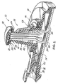
Fig. 1 is a perspective sectional view of an embodiment of the invention; -
Fig. 2 is a perspective view of an embodiment of the invention illustrating the heat shield; and -
Fig. 3 is a perspective view of an embodiment of the invention. - For a better understanding of the present invention, together with other and further objects, advantages and capabilities thereof, reference is made to the following disclosure and appended claims taken in conjunction with the above-described drawings.
- Referring now to the drawings with greater particularity, there is shown in
Fig. 1 anLED light source 10 that comprises ahousing 12 having abase 14 with ahollow core 16 projecting therefrom. Thecore 16 is substantially conical. A first printedcircuit board 18 is fitted to thebase 14. - A second printed
circuit board 20 is fitted to thenarrow end 22 of thecore 16, the second printedcircuit board 20 having at least oneLED 24 operatively fixed thereto. - In the drawings no wiring traces are shown on the printed circuit boards as the specifics of such wiring will depend on the ultimate usage of the light source and can vary widely.
- In a preferred embodiment of the invention a plurality of
LEDs 24 is used, the number depending upon the ultimate amount of light output desired. The LEDs can all emit the same color or different colors. For example, the LEDs can all emit in the red region of the spectrum if the light is to be used solely as a taillight or stoplight. However, by providing a mixture of red and amber emitting LEDs the light can also function as an amber turn signal, a requirement in some European countries. Alternatively, if all amber emitting LEDs are employed, a typical fog light function can be provided. Also, a mixture of red, green and blue emitting LEDs can provide a white light, for example, for a headlight or backup light. - A plurality of
electrical conductors 26 is provided havingproximal ends 28 attached to and extending from the second printedcircuit board 20 anddistal ends 30 attached to and projecting through said first printedcircuit board 18. Theconductors 26 can carry the electricity needed for the operation of the LEDs, as well as functioning as heat conductors for carrying away the heat generated by the operation of the LEDs, as will be further explained below. - A
cap 32 is fitted over the second printedcircuit board 20. The cap is preferably formed from a plastic material and can be metallized, as can the outer surface of the core. Alternatively, the cap could also be metal to further dissipate heat. - A
heat sink 34 is attached to thebase 14. During operation of the lamp the heat generated by the LEDs is conducted thru therods 26 to distalends 30 and then is spread across the bottom of thecircuit board 18. The heat is then dispensed to the heat sink via thermal putty. A small gap is provided between the circuit board and the heat sink to accommodate the putty. - Electrical contacts extend from inside the
housing 12 to a position outside thehousing 12 for connection to a power source, for example, to a socket wired in to the automobile's electrical system. Under ordinary circumstances, such as for an automobile taillight, three electrical contacts would be provided. InFig. 1 only two contacts, 36 and 38 are shown for clarity. - An annular O-
ring 40 is positioned between thebase 14 and theheat sink 34 to accomplish an environmental seal. - In a preferred embodiment of the invention the
hollow core 16 has anelectrical conductor aligner 42 positioned therein between the first printedcircuit board 18 and the second printedcircuit board 20 for maintaining alignment between theelectrical conductors 26. Thealigner 42 can be formed from rubber or other suitable material. Thealigner 42 also acts as a seal from the top side going down the conductors. - Likewise, in a preferred embodiment of the invention the outside surface 44 of the
hollow core 16 has multiple diameters. These multiple diameters can provide added control over the light distribution. - One of the diameters near the bottom of the core, that is, near the base, is provided with at least one and preferably three
locking flanges 48. These flanges engage a suitable opening in, for example, the base of a reflector, not shown, and allow thelight source 10 to be inserted into the opening and twisted to be locked into position. - To insure a tight and proper fit a
soft sealing gasket 50 can be provided at the junction of the core with the base to maintain a clean environment inside the reflector. - Thus there is provided an LED light source that is convenient to use and that is easily replaceable.
- While there have been shown what are at present considered to be the preferred embodiments of the invention, it will be apparent to those skilled in the art that various changes and modifications can be made herein without departing from the scope of the invention as defined by the appended claims.
Claims (9)
- An LED light source (10) comprising:a housing (12) having a base (14);a hollow core (16);a first printed circuit board (18) fitted to said base (14);a second printed circuit board (20) having at least one LED (24) operatively fixed thereto;a plurality of electrical conductors (26) having proximal ends (28) attached to and extending from said second printed circuit board (20);a cap (32) fitted over said second printed circuit board (20); anda heat sink (34) attached to said base (14)characterized in thatsaid hollow core (16) is projecting from said base (14) and being substantially conical;said second printed circuit board (20) is fitted to the narrow end of said core (16); andsaid electrical conductors (26) having distal ends (30) attached to and projecting through said first printed circuit board (18).
- The LED light source of Claim 1 wherein at least two electrical contacts (36, 38) extend from inside said housing (12) to a position outside said housing (12) for connection to a power source.
- The LED light source of claim 1 wherein an annular O-ring (40) is positioned between said base (14) and said heat sink (34).
- The LED light source of Claim 1 wherein said hollow core (14) has an electrical conductor aligner (42) positioned therein between said first printed circuit board (18) and said second printed circuit board (20) for maintaining alignment between said electrical conductors (26).
- The LED light source of Claim 1 wherein the outside surface of said hollow core (14) has multiple diameters
- The LED light source of Claim 5 wherein one of said diameters is provided with a locking flange (48).
- The LED light source of Claim 1 wherein said at least one LED (24) comprises at least two LEDs.
- The LED light source of Claim 7 wherein said at least two LEDs (24) emit light in the same color.
- The LED light source of Claim 7 wherein said at least two LEDs (24) emit light of different colors.
Applications Claiming Priority (4)
| Application Number | Priority Date | Filing Date | Title |
|---|---|---|---|
| US50726703P | 2003-09-30 | 2003-09-30 | |
| US507267P | 2003-09-30 | ||
| US10/839,365 US7166955B2 (en) | 2003-09-30 | 2004-05-05 | Multi-conductor LED bulb assembly |
| US839365 | 2004-05-05 |
Publications (3)
| Publication Number | Publication Date |
|---|---|
| EP1521033A2 EP1521033A2 (en) | 2005-04-06 |
| EP1521033A3 EP1521033A3 (en) | 2008-04-02 |
| EP1521033B1 true EP1521033B1 (en) | 2017-11-08 |
Family
ID=34316828
Family Applications (1)
| Application Number | Title | Priority Date | Filing Date |
|---|---|---|---|
| EP04020087.5A Not-in-force EP1521033B1 (en) | 2003-09-30 | 2004-08-24 | Multi-conductor LED bulb assembly, in particular for automobiles |
Country Status (3)
| Country | Link |
|---|---|
| US (1) | US7166955B2 (en) |
| EP (1) | EP1521033B1 (en) |
| CA (1) | CA2477613A1 (en) |
Families Citing this family (10)
| Publication number | Priority date | Publication date | Assignee | Title |
|---|---|---|---|---|
| US7282841B2 (en) * | 2004-11-01 | 2007-10-16 | Chia Mao Li | Lamp assembly with LED light sources including threaded heat conduction base |
| US7677766B2 (en) * | 2007-05-07 | 2010-03-16 | Lsi Industries, Inc. | LED lamp device and method to retrofit a lighting fixture |
| WO2009070815A2 (en) * | 2007-11-28 | 2009-06-04 | Peter Dennis Galatis | Lighting device |
| USD631183S1 (en) | 2008-09-23 | 2011-01-18 | Lsi Industries, Inc. | Lighting fixture |
| US8215799B2 (en) | 2008-09-23 | 2012-07-10 | Lsi Industries, Inc. | Lighting apparatus with heat dissipation system |
| DE102010030296B4 (en) * | 2010-06-21 | 2012-11-22 | Osram Ag | Lamp with concave reflector and a projection for at least one light source |
| US9383146B2 (en) * | 2012-07-20 | 2016-07-05 | Tai-Her Yang | Heat dissipation device having lateral-spreading heat dissipating and shunting heat conductive structure |
| FR3026467B1 (en) * | 2014-09-30 | 2019-10-04 | Valeo Vision | LUMINOUS MODULE COMPRISING AT LEAST ONE COMPONENT AND A CONNECTOR ARRANGED ON A HEAT SINK, AND LIGHTING DEVICE FOR A MOTOR VEHICLE COMPRISING SUCH A MODULE |
| DE102015201153A1 (en) * | 2015-01-23 | 2016-07-28 | Osram Gmbh | lighting device |
| JP7069521B2 (en) * | 2018-03-06 | 2022-05-18 | 東芝ライテック株式会社 | Manufacturing method of vehicle lighting equipment, vehicle lighting equipment, and vehicle lighting equipment |
Family Cites Families (9)
| Publication number | Priority date | Publication date | Assignee | Title |
|---|---|---|---|---|
| US6793374B2 (en) * | 1998-09-17 | 2004-09-21 | Simon H. A. Begemann | LED lamp |
| US6414801B1 (en) | 1999-01-14 | 2002-07-02 | Truck-Lite Co., Inc. | Catadioptric light emitting diode assembly |
| US6425678B1 (en) | 1999-08-23 | 2002-07-30 | Dialight Corporation | Led obstruction lamp |
| TW507858U (en) * | 2001-07-23 | 2002-10-21 | Lin Chau Tang | Energy saving lighting device with high illumination |
| US6682211B2 (en) * | 2001-09-28 | 2004-01-27 | Osram Sylvania Inc. | Replaceable LED lamp capsule |
| US6773138B2 (en) * | 2002-04-09 | 2004-08-10 | Osram Sylvania Inc. | Snap together automotive led lamp assembly |
| US7048412B2 (en) * | 2002-06-10 | 2006-05-23 | Lumileds Lighting U.S., Llc | Axial LED source |
| US7075224B2 (en) * | 2003-09-30 | 2006-07-11 | Osram Sylvania Inc. | Light emitting diode bulb connector including tension reliever |
| US6991355B1 (en) * | 2004-06-16 | 2006-01-31 | Osram Sylvania Inc. | light emitting diode lamp with light pipes |
-
2004
- 2004-05-05 US US10/839,365 patent/US7166955B2/en not_active Expired - Fee Related
- 2004-08-16 CA CA 2477613 patent/CA2477613A1/en not_active Abandoned
- 2004-08-24 EP EP04020087.5A patent/EP1521033B1/en not_active Not-in-force
Non-Patent Citations (1)
| Title |
|---|
| None * |
Also Published As
| Publication number | Publication date |
|---|---|
| CA2477613A1 (en) | 2005-03-30 |
| US7166955B2 (en) | 2007-01-23 |
| US20050067931A1 (en) | 2005-03-31 |
| EP1521033A3 (en) | 2008-04-02 |
| EP1521033A2 (en) | 2005-04-06 |
Similar Documents
| Publication | Publication Date | Title |
|---|---|---|
| CA2491772C (en) | Led bulb | |
| KR101220685B1 (en) | Three color led bulb | |
| US5567036A (en) | Clearance and side marker lamp | |
| US6276822B1 (en) | Method of replacing a conventional vehicle light bulb with a light-emitting diode array | |
| EP1521033B1 (en) | Multi-conductor LED bulb assembly, in particular for automobiles | |
| US10190745B2 (en) | Lamp assembly for use in a headlamp | |
| EP1521034B1 (en) | Light emitting diode bulb connector | |
| US10724698B2 (en) | Light source unit for lighting tool for vehicle and lighting tool for vehicle | |
| JP3660267B2 (en) | Lighting fixture | |
| EP1617135A2 (en) | Molded-in light emitting diode light source | |
| JP2007048727A (en) | Light emitting diode unit | |
| KR101683624B1 (en) | LED lamp for vehicle | |
| CA2510370A1 (en) | Stem mount for light emitting diode | |
| CN202165970U (en) | Light-emitting diode (LED) lamp device for vehicles | |
| JPS6178003A (en) | Lamp apparatus for vehicle | |
| EP3460318A2 (en) | Light source module for vehicle | |
| CN210979407U (en) | L ED decorative lamp | |
| CN212510737U (en) | Track spotlight | |
| WO2023176582A1 (en) | Light source unit for vehicular lighting fixture, and vehicular lighting fixture | |
| US20190359115A1 (en) | Vehicular lamp | |
| KR200342035Y1 (en) | Lamp for automobile | |
| KR200277840Y1 (en) | Out side mirror of car that has a light source | |
| KR200377700Y1 (en) | bulb holder for cars | |
| KR200344091Y1 (en) | The automobile front signal display device using LED | |
| KR200316807Y1 (en) | Automotive LED bulb |
Legal Events
| Date | Code | Title | Description |
|---|---|---|---|
| PUAI | Public reference made under article 153(3) epc to a published international application that has entered the european phase |
Free format text: ORIGINAL CODE: 0009012 |
|
| AK | Designated contracting states |
Kind code of ref document: A2 Designated state(s): AT BE BG CH CY CZ DE DK EE ES FI FR GB GR HU IE IT LI LU MC NL PL PT RO SE SI SK TR |
|
| AX | Request for extension of the european patent |
Extension state: AL HR LT LV MK |
|
| PUAL | Search report despatched |
Free format text: ORIGINAL CODE: 0009013 |
|
| AK | Designated contracting states |
Kind code of ref document: A3 Designated state(s): AT BE BG CH CY CZ DE DK EE ES FI FR GB GR HU IE IT LI LU MC NL PL PT RO SE SI SK TR |
|
| AX | Request for extension of the european patent |
Extension state: AL HR LT LV MK |
|
| RIC1 | Information provided on ipc code assigned before grant |
Ipc: F21V 29/00 20060101ALI20080222BHEP Ipc: F21K 7/00 20060101ALI20080222BHEP Ipc: F21S 8/10 20060101ALI20080222BHEP Ipc: F21V 19/00 20060101AFI20041220BHEP |
|
| 17P | Request for examination filed |
Effective date: 20080508 |
|
| AKX | Designation fees paid |
Designated state(s): AT BE BG CH CY CZ DE DK EE ES FI FR GB GR HU IE IT LI LU MC NL PL PT RO SE SI SK TR |
|
| 17Q | First examination report despatched |
Effective date: 20081230 |
|
| REG | Reference to a national code |
Ref country code: DE Ref legal event code: R079 Ref document number: 602004052017 Country of ref document: DE Free format text: PREVIOUS MAIN CLASS: F21V0019000000 Ipc: F21K0009000000 |
|
| GRAP | Despatch of communication of intention to grant a patent |
Free format text: ORIGINAL CODE: EPIDOSNIGR1 |
|
| RIC1 | Information provided on ipc code assigned before grant |
Ipc: F21Y 115/10 20160101ALN20170523BHEP Ipc: F21V 29/70 20150101ALI20170523BHEP Ipc: F21V 29/00 20150101ALI20170523BHEP Ipc: F21V 3/04 20060101ALI20170523BHEP Ipc: F21K 9/00 20160101AFI20170523BHEP Ipc: F21S 8/10 20060101ALI20170523BHEP Ipc: F21W 101/10 20060101ALN20170523BHEP |
|
| INTG | Intention to grant announced |
Effective date: 20170627 |
|
| GRAS | Grant fee paid |
Free format text: ORIGINAL CODE: EPIDOSNIGR3 |
|
| GRAA | (expected) grant |
Free format text: ORIGINAL CODE: 0009210 |
|
| AK | Designated contracting states |
Kind code of ref document: B1 Designated state(s): AT BE BG CH CY CZ DE DK EE ES FI FR GB GR HU IE IT LI LU MC NL PL PT RO SE SI SK TR |
|
| REG | Reference to a national code |
Ref country code: GB Ref legal event code: FG4D |
|
| REG | Reference to a national code |
Ref country code: CH Ref legal event code: EP Ref country code: AT Ref legal event code: REF Ref document number: 944467 Country of ref document: AT Kind code of ref document: T Effective date: 20171115 |
|
| REG | Reference to a national code |
Ref country code: IE Ref legal event code: FG4D |
|
| REG | Reference to a national code |
Ref country code: DE Ref legal event code: R096 Ref document number: 602004052017 Country of ref document: DE |
|
| REG | Reference to a national code |
Ref country code: NL Ref legal event code: MP Effective date: 20171108 |
|
| REG | Reference to a national code |
Ref country code: AT Ref legal event code: MK05 Ref document number: 944467 Country of ref document: AT Kind code of ref document: T Effective date: 20171108 |
|
| PG25 | Lapsed in a contracting state [announced via postgrant information from national office to epo] |
Ref country code: NL Free format text: LAPSE BECAUSE OF FAILURE TO SUBMIT A TRANSLATION OF THE DESCRIPTION OR TO PAY THE FEE WITHIN THE PRESCRIBED TIME-LIMIT Effective date: 20171108 Ref country code: FI Free format text: LAPSE BECAUSE OF FAILURE TO SUBMIT A TRANSLATION OF THE DESCRIPTION OR TO PAY THE FEE WITHIN THE PRESCRIBED TIME-LIMIT Effective date: 20171108 Ref country code: ES Free format text: LAPSE BECAUSE OF FAILURE TO SUBMIT A TRANSLATION OF THE DESCRIPTION OR TO PAY THE FEE WITHIN THE PRESCRIBED TIME-LIMIT Effective date: 20171108 Ref country code: SE Free format text: LAPSE BECAUSE OF FAILURE TO SUBMIT A TRANSLATION OF THE DESCRIPTION OR TO PAY THE FEE WITHIN THE PRESCRIBED TIME-LIMIT Effective date: 20171108 |
|
| PG25 | Lapsed in a contracting state [announced via postgrant information from national office to epo] |
Ref country code: BG Free format text: LAPSE BECAUSE OF FAILURE TO SUBMIT A TRANSLATION OF THE DESCRIPTION OR TO PAY THE FEE WITHIN THE PRESCRIBED TIME-LIMIT Effective date: 20180208 Ref country code: GR Free format text: LAPSE BECAUSE OF FAILURE TO SUBMIT A TRANSLATION OF THE DESCRIPTION OR TO PAY THE FEE WITHIN THE PRESCRIBED TIME-LIMIT Effective date: 20180209 Ref country code: AT Free format text: LAPSE BECAUSE OF FAILURE TO SUBMIT A TRANSLATION OF THE DESCRIPTION OR TO PAY THE FEE WITHIN THE PRESCRIBED TIME-LIMIT Effective date: 20171108 |
|
| PG25 | Lapsed in a contracting state [announced via postgrant information from national office to epo] |
Ref country code: SK Free format text: LAPSE BECAUSE OF FAILURE TO SUBMIT A TRANSLATION OF THE DESCRIPTION OR TO PAY THE FEE WITHIN THE PRESCRIBED TIME-LIMIT Effective date: 20171108 Ref country code: DK Free format text: LAPSE BECAUSE OF FAILURE TO SUBMIT A TRANSLATION OF THE DESCRIPTION OR TO PAY THE FEE WITHIN THE PRESCRIBED TIME-LIMIT Effective date: 20171108 Ref country code: CZ Free format text: LAPSE BECAUSE OF FAILURE TO SUBMIT A TRANSLATION OF THE DESCRIPTION OR TO PAY THE FEE WITHIN THE PRESCRIBED TIME-LIMIT Effective date: 20171108 Ref country code: EE Free format text: LAPSE BECAUSE OF FAILURE TO SUBMIT A TRANSLATION OF THE DESCRIPTION OR TO PAY THE FEE WITHIN THE PRESCRIBED TIME-LIMIT Effective date: 20171108 Ref country code: CY Free format text: LAPSE BECAUSE OF FAILURE TO SUBMIT A TRANSLATION OF THE DESCRIPTION OR TO PAY THE FEE WITHIN THE PRESCRIBED TIME-LIMIT Effective date: 20171108 |
|
| REG | Reference to a national code |
Ref country code: DE Ref legal event code: R097 Ref document number: 602004052017 Country of ref document: DE |
|
| REG | Reference to a national code |
Ref country code: FR Ref legal event code: PLFP Year of fee payment: 15 |
|
| PG25 | Lapsed in a contracting state [announced via postgrant information from national office to epo] |
Ref country code: PL Free format text: LAPSE BECAUSE OF FAILURE TO SUBMIT A TRANSLATION OF THE DESCRIPTION OR TO PAY THE FEE WITHIN THE PRESCRIBED TIME-LIMIT Effective date: 20171108 Ref country code: RO Free format text: LAPSE BECAUSE OF FAILURE TO SUBMIT A TRANSLATION OF THE DESCRIPTION OR TO PAY THE FEE WITHIN THE PRESCRIBED TIME-LIMIT Effective date: 20171108 Ref country code: IT Free format text: LAPSE BECAUSE OF FAILURE TO SUBMIT A TRANSLATION OF THE DESCRIPTION OR TO PAY THE FEE WITHIN THE PRESCRIBED TIME-LIMIT Effective date: 20171108 |
|
| PLBE | No opposition filed within time limit |
Free format text: ORIGINAL CODE: 0009261 |
|
| STAA | Information on the status of an ep patent application or granted ep patent |
Free format text: STATUS: NO OPPOSITION FILED WITHIN TIME LIMIT |
|
| 26N | No opposition filed |
Effective date: 20180809 |
|
| PG25 | Lapsed in a contracting state [announced via postgrant information from national office to epo] |
Ref country code: SI Free format text: LAPSE BECAUSE OF FAILURE TO SUBMIT A TRANSLATION OF THE DESCRIPTION OR TO PAY THE FEE WITHIN THE PRESCRIBED TIME-LIMIT Effective date: 20171108 |
|
| PG25 | Lapsed in a contracting state [announced via postgrant information from national office to epo] |
Ref country code: MC Free format text: LAPSE BECAUSE OF FAILURE TO SUBMIT A TRANSLATION OF THE DESCRIPTION OR TO PAY THE FEE WITHIN THE PRESCRIBED TIME-LIMIT Effective date: 20171108 |
|
| REG | Reference to a national code |
Ref country code: CH Ref legal event code: PL |
|
| GBPC | Gb: european patent ceased through non-payment of renewal fee |
Effective date: 20180824 |
|
| PG25 | Lapsed in a contracting state [announced via postgrant information from national office to epo] |
Ref country code: LU Free format text: LAPSE BECAUSE OF NON-PAYMENT OF DUE FEES Effective date: 20180824 Ref country code: LI Free format text: LAPSE BECAUSE OF NON-PAYMENT OF DUE FEES Effective date: 20180831 Ref country code: CH Free format text: LAPSE BECAUSE OF NON-PAYMENT OF DUE FEES Effective date: 20180831 |
|
| REG | Reference to a national code |
Ref country code: BE Ref legal event code: MM Effective date: 20180831 |
|
| PG25 | Lapsed in a contracting state [announced via postgrant information from national office to epo] |
Ref country code: BE Free format text: LAPSE BECAUSE OF NON-PAYMENT OF DUE FEES Effective date: 20180831 |
|
| PG25 | Lapsed in a contracting state [announced via postgrant information from national office to epo] |
Ref country code: GB Free format text: LAPSE BECAUSE OF NON-PAYMENT OF DUE FEES Effective date: 20180824 |
|
| PG25 | Lapsed in a contracting state [announced via postgrant information from national office to epo] |
Ref country code: TR Free format text: LAPSE BECAUSE OF FAILURE TO SUBMIT A TRANSLATION OF THE DESCRIPTION OR TO PAY THE FEE WITHIN THE PRESCRIBED TIME-LIMIT Effective date: 20171108 |
|
| PG25 | Lapsed in a contracting state [announced via postgrant information from national office to epo] |
Ref country code: PT Free format text: LAPSE BECAUSE OF FAILURE TO SUBMIT A TRANSLATION OF THE DESCRIPTION OR TO PAY THE FEE WITHIN THE PRESCRIBED TIME-LIMIT Effective date: 20171108 Ref country code: HU Free format text: LAPSE BECAUSE OF FAILURE TO SUBMIT A TRANSLATION OF THE DESCRIPTION OR TO PAY THE FEE WITHIN THE PRESCRIBED TIME-LIMIT; INVALID AB INITIO Effective date: 20040824 |
|
| PG25 | Lapsed in a contracting state [announced via postgrant information from national office to epo] |
Ref country code: IE Free format text: LAPSE BECAUSE OF NON-PAYMENT OF DUE FEES Effective date: 20180824 |
|
| PGFP | Annual fee paid to national office [announced via postgrant information from national office to epo] |
Ref country code: FR Payment date: 20210819 Year of fee payment: 18 |
|
| PGFP | Annual fee paid to national office [announced via postgrant information from national office to epo] |
Ref country code: DE Payment date: 20210819 Year of fee payment: 18 |
|
| REG | Reference to a national code |
Ref country code: DE Ref legal event code: R119 Ref document number: 602004052017 Country of ref document: DE |
|
| PG25 | Lapsed in a contracting state [announced via postgrant information from national office to epo] |
Ref country code: FR Free format text: LAPSE BECAUSE OF NON-PAYMENT OF DUE FEES Effective date: 20220831 Ref country code: DE Free format text: LAPSE BECAUSE OF NON-PAYMENT OF DUE FEES Effective date: 20230301 |
|
| P01 | Opt-out of the competence of the unified patent court (upc) registered |
Effective date: 20230821 |