EP1520951B1 - Eine Schiebevorrichtung, ein Fenster mit einer solchen Schiebevorrichtung und Verfahren zum Montieren eines Flügels in einem solchen Fenster - Google Patents
Eine Schiebevorrichtung, ein Fenster mit einer solchen Schiebevorrichtung und Verfahren zum Montieren eines Flügels in einem solchen Fenster Download PDFInfo
- Publication number
- EP1520951B1 EP1520951B1 EP04388067A EP04388067A EP1520951B1 EP 1520951 B1 EP1520951 B1 EP 1520951B1 EP 04388067 A EP04388067 A EP 04388067A EP 04388067 A EP04388067 A EP 04388067A EP 1520951 B1 EP1520951 B1 EP 1520951B1
- Authority
- EP
- European Patent Office
- Prior art keywords
- rail
- window
- sliding device
- slide
- sash
- Prior art date
- Legal status (The legal status is an assumption and is not a legal conclusion. Google has not performed a legal analysis and makes no representation as to the accuracy of the status listed.)
- Expired - Lifetime
Links
Images
Classifications
-
- E—FIXED CONSTRUCTIONS
- E05—LOCKS; KEYS; WINDOW OR DOOR FITTINGS; SAFES
- E05D—HINGES OR SUSPENSION DEVICES FOR DOORS, WINDOWS OR WINGS
- E05D15/00—Suspension arrangements for wings
- E05D15/40—Suspension arrangements for wings supported on arms movable in vertical planes
- E05D15/44—Suspension arrangements for wings supported on arms movable in vertical planes with pivoted arms and vertically-sliding guides
-
- E—FIXED CONSTRUCTIONS
- E05—LOCKS; KEYS; WINDOW OR DOOR FITTINGS; SAFES
- E05D—HINGES OR SUSPENSION DEVICES FOR DOORS, WINDOWS OR WINGS
- E05D15/00—Suspension arrangements for wings
- E05D15/16—Suspension arrangements for wings for wings sliding vertically more or less in their own plane
- E05D15/22—Suspension arrangements for wings for wings sliding vertically more or less in their own plane allowing an additional movement
-
- E—FIXED CONSTRUCTIONS
- E05—LOCKS; KEYS; WINDOW OR DOOR FITTINGS; SAFES
- E05Y—INDEXING SCHEME ASSOCIATED WITH SUBCLASSES E05D AND E05F, RELATING TO CONSTRUCTION ELEMENTS, ELECTRIC CONTROL, POWER SUPPLY, POWER SIGNAL OR TRANSMISSION, USER INTERFACES, MOUNTING OR COUPLING, DETAILS, ACCESSORIES, AUXILIARY OPERATIONS NOT OTHERWISE PROVIDED FOR, APPLICATION THEREOF
- E05Y2201/00—Constructional elements; Accessories therefor
- E05Y2201/60—Suspension or transmission members; Accessories therefor
- E05Y2201/606—Accessories therefor
- E05Y2201/61—Cooperation between suspension or transmission members
- E05Y2201/612—Cooperation between suspension or transmission members between carriers and rails
- E05Y2201/614—Anti-derailing means
-
- E—FIXED CONSTRUCTIONS
- E05—LOCKS; KEYS; WINDOW OR DOOR FITTINGS; SAFES
- E05Y—INDEXING SCHEME ASSOCIATED WITH SUBCLASSES E05D AND E05F, RELATING TO CONSTRUCTION ELEMENTS, ELECTRIC CONTROL, POWER SUPPLY, POWER SIGNAL OR TRANSMISSION, USER INTERFACES, MOUNTING OR COUPLING, DETAILS, ACCESSORIES, AUXILIARY OPERATIONS NOT OTHERWISE PROVIDED FOR, APPLICATION THEREOF
- E05Y2800/00—Details, accessories and auxiliary operations not otherwise provided for
- E05Y2800/74—Specific positions
- E05Y2800/742—Specific positions abnormal
- E05Y2800/744—Specific positions abnormal cleaning or service
-
- E—FIXED CONSTRUCTIONS
- E05—LOCKS; KEYS; WINDOW OR DOOR FITTINGS; SAFES
- E05Y—INDEXING SCHEME ASSOCIATED WITH SUBCLASSES E05D AND E05F, RELATING TO CONSTRUCTION ELEMENTS, ELECTRIC CONTROL, POWER SUPPLY, POWER SIGNAL OR TRANSMISSION, USER INTERFACES, MOUNTING OR COUPLING, DETAILS, ACCESSORIES, AUXILIARY OPERATIONS NOT OTHERWISE PROVIDED FOR, APPLICATION THEREOF
- E05Y2900/00—Application of doors, windows, wings or fittings thereof
- E05Y2900/10—Application of doors, windows, wings or fittings thereof for buildings or parts thereof
- E05Y2900/13—Type of wing
- E05Y2900/148—Windows
Definitions
- the present invention relates to an assembly for windows comprising a sliding device and a substantially U-shaped rail adapted to be provided at a front side of a window frame, the sliding device comprising a slide member having a slide shoe, said slide shoe being adapted to engage the substantially U-shaped rail comprising a bottom wall, a side wall and a front wall.
- the front wall has a backside facing away from the bottom wall.
- the invention further relates to a window having such an assembly and a method for mounting a sash in such a window.
- Such sliding devices are known i.a. from reversible windows.
- the known sliding devices have a rail with a comparatively deep U-shape and correspondingly a comparatively big slide shoe, as there would otherwise be a risk that the slide shoe during use might fall out from the rail, which under unlucky circumstances may damage the window and at all events cause trouble for the user, which is to bring the slide shoe back into the rail to enable the window to function correctly.
- Such known sliding devices are therefore comparatively big, which makes them less suited for new window types, where the space for the fittings of the window is limited.
- Another kind of sliding device uses partially closed rails, i.e. with C-shaped cross section, such that the slide shoe is retained against removal.
- This kind of sliding device ensures a good securing of the slide shoe in the rail, but it is on the other hand difficult to get the slide shoe in and out of engagement with the rail as required during mounting and dismounting of the window.
- the slide shoe is thus to be introduced into the rail from one end thereof, or a recess should be provided in the rail, such that the slide shoe can be taken out of the rail at a certain place, which, however, increases the risk of the slide shoe unintentionally disengaging the rail, and at the same time it is difficult to take out the block, as it is to be positioned on precisely the right place to be removed from the rail.
- US 1,543,956 discloses a sash mounting showing all the features of the preamble of claim 1.
- WO 96/23125 discloses a window stay.
- an assembly according to claim 1 comprises a safety member adapted to releasably engage the slide member, said safety member being in the mounted condition of the sliding device in engagement with a backside of the side wall of the rail.
- Said safety member in the mounted condition of the sliding device, is in abutment against the backside of the front wall of the rail and at the same time in engagement with a backside of the side wall of the rail and furthermore in engagement with the slide member to ensure that the slide shoe will not unintentionally disengage the rail during use.
- the safety member may be a loose member adapted to be connected with the sliding member after mounting of the slide shoe in the rail, for instance with securing means, like a screw, a bolt or a snap connector, but according to a preferred embodiment the safety member is displaceably connected to the slide member to be displaced from a first position at a distance from the slide shoe to a second position, in which the safety member at least partially overlaps the slide shoe.
- the sliding device comprises means for a varied frictional engagement between the sliding device and the rail.
- a window with a frame and a sash comprising a tension bar, a compression bar, a rail and a sliding device.
- the window is characterized in that the sash is connected to the frame by means of an assembly according to the invention.
- An embodiment is characterized in that the rail is provided with means for the attainment of a varied frictional engagement with the sliding device on one or more of its sides over the whole or over a part of its length.
- This embodiment makes it possible to attain a varying friction over the opening angle of the window, for instance in such a manner that the window has a holding function in chosen angle positions or has a child proofing by means of a point, where the window slides tightly, such that a child cannot open the window fully.
- the friction coating may be adapted to compensate for the fact that the slide shoe does not move equally much in all the angle areas, such that in spite of this, a fairly uniform resistance against opening and closing is attained.
- the sliding device is easy to move, for which reason the slide shoe, the rail and the safety member may be adapted to a low mutual friction over the major part of the length of the rail, whereas at predetermined places a high friction is established.
- a third aspect of the invention relates to a method for mounting a sash for a reversible window, comprising the steps according to claim 12.
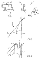
- a slide member 2 which constitutes a part of a sliding device 1, is shown in a lateral view in Fig. 1 .
- the slide member 2 comprises a slide shoe 3 extending along a side edge.
- the slide member 2 may, as shown, be a comparatively small fitting adapted to be connected to a further member, like a sash of a reversible window, for instance by means of an eye 11.
- the slide member 2 has, moreover, a leg 16, the function of which will be explained in the following.
- Fig. 2 is an end view of the slide member 2 and a rail 4, said rail comprising a bottom wall 5, a sidewall 6 and a front wall 7.
- the slide shoe 3 may be a bent metal leg, which is appropriately provided with an outer layer of plastic, whereby a slide shoe 3 is established, said slide shoe being easily displaceable in the rail 4 without any noise. If a particularly small resistance against displacement of the slide shoe 3 in the rail 4 is required, the slide shoe 3 may be provided with an exterior coating of a friction-dampening material, such as Teflon. Alternatively or supplementary the rail 4 may be provided with friction-dampening material on the surfaces, where the slide shoe 3 slides.
- a considerable friction between the slide shoe 3 and the rail 4 is desirable for instance in order to obtain a holding function, such that the window may be open in a ventilating position, and in that case the slide shoe 3 and/or the rail 4 may be provided with a friction-increasing surface, for instance at selected places along the length of the rail.
- the rail 4 may be dimensioned in such a manner that the slide shoe 3 slides comparatively tight-fittingly in the rail 4 over the whole length thereof or solely at selected places.
- a suitable use for such a sliding device 1 is as a guide for a sash 13 relative to a frame 23 of a reversible window 12 known per se, as illustrated in a slightly open position in Fig. 3 .
- the design of such a reversible window will be described in consideration of principles only.
- the sash 13 of the reversible window 12 is mounted in a guide member comprising a tension bar 33, the upper end of which is rotatably connected to the frame 23, and the lower end of which is connected to a compression bar 43.
- One end of the compression bar 43 is connected to the sash substantially at its central body and the other end is displaceably connected to the frame 23.
- the sash 13 is at its upper edge displaceably connected to the frame 23 by means of the sliding device 1 according to the invention, which is more clearly seen in Fig. 4 , which is an enlarged part view of a sash corner of the reversible window. It will be seen here, how the slide member 2 is connected to the sash 13 at the eye 11, whereas the slide shoe 3 of the sliding device is inserted in the rail 4. In this manner the upper edge of the sash 13 is displaceable along the front side of the window frame, such that the sash 13 can be turned completely over, whereby for instance cleaning of the window is facilitated.
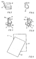
- Figs 5 and 6 show a lateral view and an end view, respectively, of a safety member 8.
- the safety member 8 comprises an arm 14 functioning as a pre-stressing member and a locking member, which will be explained in detail below.
- the safety member may preferably be manufactured from a suitable plastic material.
- the safety member 8 may be manufactured from a material comprising hard particles, if at all, solely at the abutment surfaces against the rail in the mounted position of the safety member.
- the safety member 8 may have a surface of a friction-dampening material, for instance Teflon.
- Fig. 7 is a cross section through the sliding device 1 in a position during mounting or dismounting of the sash relative to the frame.
- the safety member 8 is positioned somewhat at a distance from the rail 4, the end 14a being brought out of engagement with the leg 16. In this position it is thus possible to insert the slide shoe 3 in the rail 4 during mounting or to remove the slide shoe 3 from the rail during dismounting.
- the safety member 8 can be further displaced relative to the slide shoe 3, such that the edge 15 (shown more clearly in Fig. 6 ) goes completely clear of the slide shoe.
- Fig. 8 is a cross section through the sliding device 1 in its mounted position, in which the slide shoe 3 is inserted in the rail 4, and in which the safety member 8 is in abutment against the front wall 7 of the rail 4.
- the edge 15 of the safety member 8 is positioned at a backside 6a of the side wall 6, such that the slide shoe 3 is prevented from being removed from the rail 4.
- the end 14a of the arm 14 is in this mounted position of the sliding device in engagement with the leg 16 on the slide member 2, such that the safety member 8 is prevented from being removed from the rail 4.
- the leg 16 prevents the safety member 8 from being displaced relative to the slide member 2 in the direction of the rail 4.
- the safety member 8 may, moreover, be adapted, in a manner not shown in detail, to be retained at differing distances from the rail 4, whereby is achieved that the friction of the sliding device against the rail 4 is adjustable. This may for instance take place in a stepless manner by fastening the safety member 8 with screws in the desired position, or stepwise for instance by engagement between a leg of the safety member 8 and a hole in the slide member 2, or for instance thereby that the arm 14 is provided with a row of notches for engagement with the leg 16, alternatively thereby that the end 14a of the arm 14 may engage the underside of the leg 16.
- the sliding device may be provided with a pressure member in the form of for instance a leaf spring, which increases the friction against the rail.
- connection devices like cam mechanisms or the like, which makes it possible to shift manually or automatically between a condition, in which the friction is very low, and a condition, in which the friction is very high.
- the actuation thereof may for instance take place at predetermined places along the rail by means of actuating means provided on or in the rail itself.
- Fig. 9 is a schematic view of a sash 13 for a reversible window 12 during the mounting of the sash 13 on the frame 23. It will be seen that the sash 13 is positioned slightly askew, such that the horizontal distance between the slide shoes gets smaller, following which the slide shoes 3 may be introduced in the rail at the respective sides of the frame.
- the window is preferably designed in such a manner that the sash 13 has substantially the same circumference as the frame 23 and in such a manner that the tension bar 33 is situated at or close to the exterior edge of the frame 23, for instance 1-2 mm from the frame. This means that the tension bar will be only slightly visible, when the window is closed. When the window is turned over, for instance to attain a cleaning position, the tension bar 33 will slightly touch the edge of the sash 13.
- the rail 4 may preferably be manufactured by extrusion from aluminium, whereby a comparatively strong and low-cost rail is attained.
- the rail 4 may furthermore preferably be provided with a mounting means 17, for instance in the form of one or more protruding flanges or a longitudinal wall part adapted to be secured to the frame.
Landscapes
- Engineering & Computer Science (AREA)
- Mechanical Engineering (AREA)
- Wing Frames And Configurations (AREA)
- Window Of Vehicle (AREA)
- Support Devices For Sliding Doors (AREA)
Claims (12)
- Vorrichtung für Fenster umfassend eine Schiebevorrichtung (1) und eine im Wesentlichen U-förmige Schiene (4), welche dazu ausgebildet ist, an einer Vorderseite eines Fensterrahmens vorgesehen zu sein, wobei die im Wesentlichen U-förmige Schiene (4) eine Bodenwand (5), eine Seitenwand (6) und eine Vorderwand (7) aufweist, wobei die Seitenwand (6) die Bodenwand (5) und die Vorderwand (7) verbindet und eine der Bodenwand (5) und der Vorderwand (7) abgewandte Rückseite (6a) aufweist, wobei die Vorderwand (7) eine der Bodenwand (5) abgewandte Rückseite (7a) aufweist, wobei die Schiebevorrichtung (1) ein Schiebeelement (2) umfasst, welches einen Gleitschuh (3) aufweist, welcher dazu ausgebildet ist, mit der im Wesentlichen U-förmigen Schiene (4) in Eingriff zu gelangen und in der Schiene (4) zwischen der Bodenwand (5) und der Vorderwand (7) verschieblich ist, wobei die Schiebevorrichtung (1) ferner ein Sicherheitselement (8) aufweist, welches sich mit dem Schiebeelement (2) im lösbaren Eingriff befindet, dadurch gekennzeichnet, dass das Sicherheitselement (8) im montieren Zustand der Schiebevorrichtung an der Rückseite (7a) der Vorderwand (7) der Schiene (4) anliegt und sich gleichzeitig mit der Rückseite (6a) der Vorderwand (6) der Schiene (4) im Eingriff befindet und sich ferner mit dem Schiebeelement (2) im Eingriff befindet, um zu sichern, dass der Gleitschuh während des Gebrauchs nicht unbeabsichtlich mit der Schiene außer Eingriff gelangt.
- Vorrichtung nach Anspruch 1, dadurch gekennzeichnet, dass das Sicherheitselement (8) zum Verschieben während des Montierens von einer ersten Stellung in einem Abstand von dem Gleitschuh (3) in eine zweite Stellung, in welcher das Sicherheitselement (8) den Gleitschuh (3) zumindest teilweise überlappt, mit dem Schiebeelement (2) verschieblich verbunden ist.
- Vorrichtung nach einem der Ansprüche 1 und 2, dadurch gekennzeichnet, dass die Schiebevorrichtung (1) Organe für einen abwechselnden Reibschluss zwischen der Schiebevorrichtung (1) und der Schiene (4) aufweist.
- Vorrichtung nach Anspruch 3, dadurch gekennzeichnet, dass das Sicherheitselement (8) Organe für einen Reibschluss mit der Schiene (4) aufweist.
- Vorrichtung nach Anspruch 3 oder 4, dadurch gekennzeichnet, dass der Gleitschuh (3) ein Reibungsmaterial umfasst.
- Vorrichtung nach einem der Ansprüche 3 bis 5, dadurch gekennzeichnet, dass die Schiebevorrichtung ein Vorspannelement aufweist.
- Vorrichtung nach einem der vorgehenden Ansprüche, dadurch gekennzeichnet, dass die lösbare Verbindung zwischen dem Schiebelement und dem Sicherheitselement im montierten Zustand durch einen Arm (14) verriegelt ist.
- Fenster (12) mit einem Rahmen (23) und einem Flügelrahmen (13) umfassend eine Spannleiste (33), eine Kompressionsstange (43), eine Schiene (4) und eine Schiebevorrichtung (1), dadurch gekennzeichnet, dass der Flügelrahmen (13) mittels der Vorrichtung nach einem der Ansprüche 1 bis 7 mit dem Rahmen (23) verbunden ist.
- Fenster (12) nach Anspruch 8, dadurch gekennzeichnet, dass die Schiene (4) mit Organen zum Festhalten eines abwechselnden Reibschlusses mit der Schiebevorrichtung an einer oder mehreren ihrer Seiten über die gesamte oder über einen Teil ihrer Länge ausgestattet ist.
- Fenster (12) nach Anspruch 8 oder 9, dadurch gekennzeichnet, dass der Gleitschuh (3), die Schiene (4) und das Sicherheitselement (8) dazu ausgebildet sind, eine geringe gegenseitige Reibung über den größten Teil der Länge der Schiene auszuweisen, während an vorgegebenen Stellen eine hohe Reibung etabliert ist.
- Fenster (12) nach einem der Ansprüche 8 bis 10, dadurch gekennzeichnet, dass der Umfang des Flügelrahmens (13) im Wesentlichen dem des Rahmens (23) entspricht, und wobei die Spannleiste (33) am äußeren Rand oder in der Nähe des äußeren Randes des Rahmens (23) angeordnet ist.
- Verfahren zum Montieren eines Flügelrahmens (13) für ein reversierbares Fenster (12) mittels einer Vorrichtung nach Anspruch 1, umfassend die folgenden Schritte:Vorsehen eines Rahmens (23),Vorsehen eines Flügelrahmens (13),Vorsehen eines Satzes von Schienen mit einem im Wesentlichen U-förmigen Querschnitt an einer Vorderseite des Rahmens, welche Schienen (4) sich gegen die Öffnung des Fensters öffnen, wobei jede Schiene (4) eine Bodenwand (5), eine Seitenwand (6) und eine Vorderwand (7) aufweist, wobei die Seitenwand (6) die Bodenwand (5) und die Vorderwand (7) verbindet und eine der Bodenwand (5) und der Vorderwand (7) abgewandte Rückseite (6a) aufweist, wobei die Vorderwand (7) eine der Bodenwand (5) abgewandte Rückseite (7a) aufweist,Vorsehen zweier Schiebevorrichtungen (1) umfassend einen Satz von Gleitschuhen (3) am Flügelrahmen (13),Einsetzen der Gleitschuhe (3) in die Schienen (4) durch Kippen des Flügelrahmens relativ zum Rahmen (23),gekennzeichnet durch den weiteren Schritt der Betätigung eines an der Schiebevorrichtung (1) vorgesehenen Sicherheitselements (8) derart, dass das Sicherheitselement (8) zur Anlage an der Schiene (4) an der Rückseite (7a) der Vorderwand (7) und gleichzeitig in Eingriff mit der Rückseite (6a) der Seitenwand (6) der Schiene (4) und ferner in Eingriff mit dem Schiebeelement (2) gebracht wird, wodurch ein Lösen des Gleitschuhs (3) von der Schiene (4) während des Gebrauchs verhindert wird.
Applications Claiming Priority (2)
| Application Number | Priority Date | Filing Date | Title |
|---|---|---|---|
| DK200301454A DK200301454A (da) | 2003-10-03 | 2003-10-03 | Gliderindretning, vindue med en sådan gliderindretning samt fremgangsmåde til montering af en ramme i et sådant vindue |
| DK200301454 | 2003-10-03 |
Publications (3)
| Publication Number | Publication Date |
|---|---|
| EP1520951A2 EP1520951A2 (de) | 2005-04-06 |
| EP1520951A3 EP1520951A3 (de) | 2010-05-12 |
| EP1520951B1 true EP1520951B1 (de) | 2012-12-26 |
Family
ID=34306700
Family Applications (1)
| Application Number | Title | Priority Date | Filing Date |
|---|---|---|---|
| EP04388067A Expired - Lifetime EP1520951B1 (de) | 2003-10-03 | 2004-10-01 | Eine Schiebevorrichtung, ein Fenster mit einer solchen Schiebevorrichtung und Verfahren zum Montieren eines Flügels in einem solchen Fenster |
Country Status (3)
| Country | Link |
|---|---|
| EP (1) | EP1520951B1 (de) |
| DK (2) | DK200301454A (de) |
| NO (1) | NO20044196L (de) |
Cited By (1)
| Publication number | Priority date | Publication date | Assignee | Title |
|---|---|---|---|---|
| EP4435216A1 (de) * | 2023-03-21 | 2024-09-25 | FAKRO PP Sp. z o.o. | Dachfensterscharnier und dachfenster mit diesem scharnier |
Families Citing this family (2)
| Publication number | Priority date | Publication date | Assignee | Title |
|---|---|---|---|---|
| DK179893B9 (en) * | 2017-11-24 | 2019-10-03 | Vkr Holding A/S | Lifting device including a sledge system for installation in a roof window and a roof window comprising such a lifting device |
| CN116905920A (zh) * | 2023-08-15 | 2023-10-20 | 北京木易东方科技有限公司 | 一种外开窗可擦窗铰链及窗户 |
Family Cites Families (3)
| Publication number | Priority date | Publication date | Assignee | Title |
|---|---|---|---|---|
| US1543956A (en) * | 1924-04-14 | 1925-06-30 | Arthur C Soule | Sash mounting |
| AU4630196A (en) * | 1995-01-24 | 1996-08-14 | Interlock Industries Limited | A window stay |
| WO2003018946A1 (en) * | 2001-08-22 | 2003-03-06 | Vkr Holding A/S | A reversible window, use thereof and a guide device for a reversible window |
-
2003
- 2003-10-03 DK DK200301454A patent/DK200301454A/da not_active Application Discontinuation
-
2004
- 2004-10-01 DK DK04388067.3T patent/DK1520951T3/da active
- 2004-10-01 EP EP04388067A patent/EP1520951B1/de not_active Expired - Lifetime
- 2004-10-01 NO NO20044196A patent/NO20044196L/no not_active Application Discontinuation
Cited By (1)
| Publication number | Priority date | Publication date | Assignee | Title |
|---|---|---|---|---|
| EP4435216A1 (de) * | 2023-03-21 | 2024-09-25 | FAKRO PP Sp. z o.o. | Dachfensterscharnier und dachfenster mit diesem scharnier |
Also Published As
| Publication number | Publication date |
|---|---|
| NO20044196L (no) | 2005-04-04 |
| EP1520951A2 (de) | 2005-04-06 |
| EP1520951A3 (de) | 2010-05-12 |
| DK1520951T3 (da) | 2013-03-18 |
| DK200301454A (da) | 2005-04-04 |
Similar Documents
| Publication | Publication Date | Title |
|---|---|---|
| US11725834B2 (en) | Window frame for air conditioner unit and air conditioner unit for use therewith | |
| EP3249132B1 (de) | Dachfenster | |
| US8627602B2 (en) | Gate assembly | |
| EP1437466A1 (de) | Sicherheitstürschloss | |
| EP2777458A1 (de) | Abnehmbares Kopfteil für eine Duschtürschienenanordnung | |
| CA2585074C (en) | A latch | |
| TWI678172B (zh) | 具有覆蓋型材的抽屜側壁以及具有該抽屜側壁的抽屜 | |
| US20070089841A1 (en) | Head rail and support bracket | |
| AU734102B2 (en) | Improvements in window stays | |
| EP1520951B1 (de) | Eine Schiebevorrichtung, ein Fenster mit einer solchen Schiebevorrichtung und Verfahren zum Montieren eines Flügels in einem solchen Fenster | |
| US20090302723A1 (en) | Door for a household appliance | |
| JP6456845B2 (ja) | ガイドレールを介して誘導方向に家具部品を誘導するための走行部、および家具用建具 | |
| EP1921214A1 (de) | Duschkopfverstellanordnung | |
| AU2002211125B2 (en) | A restrictor device | |
| JP2016510370A5 (de) | ||
| CA2152020A1 (en) | Window lock | |
| AU2002211125A1 (en) | A restrictor device | |
| AU758753B2 (en) | A releasable restrictor device | |
| CN101435302B (zh) | 角部支承装置 | |
| EP4415582B1 (de) | Anti-freigabe-wandeinheitsstützvorrichtung | |
| AU2004201359B2 (en) | A Security Bolt | |
| AU6387194A (en) | A window stay | |
| RU2798561C2 (ru) | Фурнитура створки для мебели | |
| KR200189766Y1 (ko) | 미닫이창의 자동 잠금장치 | |
| US20220341228A1 (en) | Locking handle mechanism |
Legal Events
| Date | Code | Title | Description |
|---|---|---|---|
| PUAI | Public reference made under article 153(3) epc to a published international application that has entered the european phase |
Free format text: ORIGINAL CODE: 0009012 |
|
| AK | Designated contracting states |
Kind code of ref document: A2 Designated state(s): AT BE BG CH CY CZ DE DK EE ES FI FR GB GR HU IE IT LI LU MC NL PL PT RO SE SI SK TR |
|
| AX | Request for extension of the european patent |
Extension state: AL HR LT LV MK |
|
| RAP1 | Party data changed (applicant data changed or rights of an application transferred) |
Owner name: VKR HOLDING A/S |
|
| PUAL | Search report despatched |
Free format text: ORIGINAL CODE: 0009013 |
|
| AK | Designated contracting states |
Kind code of ref document: A3 Designated state(s): AT BE BG CH CY CZ DE DK EE ES FI FR GB GR HU IE IT LI LU MC NL PL PT RO SE SI SK TR |
|
| AX | Request for extension of the european patent |
Extension state: AL HR LT LV MK |
|
| 17P | Request for examination filed |
Effective date: 20101102 |
|
| AKX | Designation fees paid |
Designated state(s): AT BE BG CH CY CZ DE DK EE ES FI FR GB GR HU IE IT LI LU MC NL PL PT RO SE SI SK TR |
|
| 17Q | First examination report despatched |
Effective date: 20110412 |
|
| GRAP | Despatch of communication of intention to grant a patent |
Free format text: ORIGINAL CODE: EPIDOSNIGR1 |
|
| GRAS | Grant fee paid |
Free format text: ORIGINAL CODE: EPIDOSNIGR3 |
|
| GRAA | (expected) grant |
Free format text: ORIGINAL CODE: 0009210 |
|
| AK | Designated contracting states |
Kind code of ref document: B1 Designated state(s): AT BE BG CH CY CZ DE DK EE ES FI FR GB GR HU IE IT LI LU MC NL PL PT RO SE SI SK TR |
|
| REG | Reference to a national code |
Ref country code: GB Ref legal event code: FG4D |
|
| REG | Reference to a national code |
Ref country code: CH Ref legal event code: EP |
|
| REG | Reference to a national code |
Ref country code: AT Ref legal event code: REF Ref document number: 590591 Country of ref document: AT Kind code of ref document: T Effective date: 20130115 |
|
| REG | Reference to a national code |
Ref country code: DE Ref legal event code: R096 Ref document number: 602004040526 Country of ref document: DE Effective date: 20130228 |
|
| REG | Reference to a national code |
Ref country code: DK Ref legal event code: T3 |
|
| PG25 | Lapsed in a contracting state [announced via postgrant information from national office to epo] |
Ref country code: FI Free format text: LAPSE BECAUSE OF FAILURE TO SUBMIT A TRANSLATION OF THE DESCRIPTION OR TO PAY THE FEE WITHIN THE PRESCRIBED TIME-LIMIT Effective date: 20121226 Ref country code: SE Free format text: LAPSE BECAUSE OF FAILURE TO SUBMIT A TRANSLATION OF THE DESCRIPTION OR TO PAY THE FEE WITHIN THE PRESCRIBED TIME-LIMIT Effective date: 20121226 |
|
| REG | Reference to a national code |
Ref country code: AT Ref legal event code: MK05 Ref document number: 590591 Country of ref document: AT Kind code of ref document: T Effective date: 20121226 |
|
| REG | Reference to a national code |
Ref country code: NL Ref legal event code: VDEP Effective date: 20121226 |
|
| PG25 | Lapsed in a contracting state [announced via postgrant information from national office to epo] |
Ref country code: GR Free format text: LAPSE BECAUSE OF FAILURE TO SUBMIT A TRANSLATION OF THE DESCRIPTION OR TO PAY THE FEE WITHIN THE PRESCRIBED TIME-LIMIT Effective date: 20130327 Ref country code: SI Free format text: LAPSE BECAUSE OF FAILURE TO SUBMIT A TRANSLATION OF THE DESCRIPTION OR TO PAY THE FEE WITHIN THE PRESCRIBED TIME-LIMIT Effective date: 20121226 |
|
| PG25 | Lapsed in a contracting state [announced via postgrant information from national office to epo] |
Ref country code: ES Free format text: LAPSE BECAUSE OF FAILURE TO SUBMIT A TRANSLATION OF THE DESCRIPTION OR TO PAY THE FEE WITHIN THE PRESCRIBED TIME-LIMIT Effective date: 20130406 Ref country code: EE Free format text: LAPSE BECAUSE OF FAILURE TO SUBMIT A TRANSLATION OF THE DESCRIPTION OR TO PAY THE FEE WITHIN THE PRESCRIBED TIME-LIMIT Effective date: 20121226 Ref country code: CZ Free format text: LAPSE BECAUSE OF FAILURE TO SUBMIT A TRANSLATION OF THE DESCRIPTION OR TO PAY THE FEE WITHIN THE PRESCRIBED TIME-LIMIT Effective date: 20121226 Ref country code: SK Free format text: LAPSE BECAUSE OF FAILURE TO SUBMIT A TRANSLATION OF THE DESCRIPTION OR TO PAY THE FEE WITHIN THE PRESCRIBED TIME-LIMIT Effective date: 20121226 Ref country code: BG Free format text: LAPSE BECAUSE OF FAILURE TO SUBMIT A TRANSLATION OF THE DESCRIPTION OR TO PAY THE FEE WITHIN THE PRESCRIBED TIME-LIMIT Effective date: 20130326 Ref country code: AT Free format text: LAPSE BECAUSE OF FAILURE TO SUBMIT A TRANSLATION OF THE DESCRIPTION OR TO PAY THE FEE WITHIN THE PRESCRIBED TIME-LIMIT Effective date: 20121226 Ref country code: CY Free format text: LAPSE BECAUSE OF FAILURE TO SUBMIT A TRANSLATION OF THE DESCRIPTION OR TO PAY THE FEE WITHIN THE PRESCRIBED TIME-LIMIT Effective date: 20121226 Ref country code: BE Free format text: LAPSE BECAUSE OF FAILURE TO SUBMIT A TRANSLATION OF THE DESCRIPTION OR TO PAY THE FEE WITHIN THE PRESCRIBED TIME-LIMIT Effective date: 20121226 |
|
| PG25 | Lapsed in a contracting state [announced via postgrant information from national office to epo] |
Ref country code: PL Free format text: LAPSE BECAUSE OF FAILURE TO SUBMIT A TRANSLATION OF THE DESCRIPTION OR TO PAY THE FEE WITHIN THE PRESCRIBED TIME-LIMIT Effective date: 20121226 Ref country code: PT Free format text: LAPSE BECAUSE OF FAILURE TO SUBMIT A TRANSLATION OF THE DESCRIPTION OR TO PAY THE FEE WITHIN THE PRESCRIBED TIME-LIMIT Effective date: 20130426 Ref country code: NL Free format text: LAPSE BECAUSE OF FAILURE TO SUBMIT A TRANSLATION OF THE DESCRIPTION OR TO PAY THE FEE WITHIN THE PRESCRIBED TIME-LIMIT Effective date: 20121226 Ref country code: RO Free format text: LAPSE BECAUSE OF FAILURE TO SUBMIT A TRANSLATION OF THE DESCRIPTION OR TO PAY THE FEE WITHIN THE PRESCRIBED TIME-LIMIT Effective date: 20121226 |
|
| PLBE | No opposition filed within time limit |
Free format text: ORIGINAL CODE: 0009261 |
|
| STAA | Information on the status of an ep patent application or granted ep patent |
Free format text: STATUS: NO OPPOSITION FILED WITHIN TIME LIMIT |
|
| 26N | No opposition filed |
Effective date: 20130927 |
|
| PG25 | Lapsed in a contracting state [announced via postgrant information from national office to epo] |
Ref country code: IT Free format text: LAPSE BECAUSE OF FAILURE TO SUBMIT A TRANSLATION OF THE DESCRIPTION OR TO PAY THE FEE WITHIN THE PRESCRIBED TIME-LIMIT Effective date: 20121226 |
|
| REG | Reference to a national code |
Ref country code: DE Ref legal event code: R097 Ref document number: 602004040526 Country of ref document: DE Effective date: 20130927 |
|
| PG25 | Lapsed in a contracting state [announced via postgrant information from national office to epo] |
Ref country code: MC Free format text: LAPSE BECAUSE OF FAILURE TO SUBMIT A TRANSLATION OF THE DESCRIPTION OR TO PAY THE FEE WITHIN THE PRESCRIBED TIME-LIMIT Effective date: 20121226 |
|
| REG | Reference to a national code |
Ref country code: CH Ref legal event code: PL |
|
| REG | Reference to a national code |
Ref country code: IE Ref legal event code: MM4A |
|
| PG25 | Lapsed in a contracting state [announced via postgrant information from national office to epo] |
Ref country code: CH Free format text: LAPSE BECAUSE OF NON-PAYMENT OF DUE FEES Effective date: 20131031 Ref country code: LI Free format text: LAPSE BECAUSE OF NON-PAYMENT OF DUE FEES Effective date: 20131031 |
|
| REG | Reference to a national code |
Ref country code: FR Ref legal event code: ST Effective date: 20140630 |
|
| REG | Reference to a national code |
Ref country code: DE Ref legal event code: R119 Ref document number: 602004040526 Country of ref document: DE Effective date: 20140501 |
|
| PG25 | Lapsed in a contracting state [announced via postgrant information from national office to epo] |
Ref country code: DE Free format text: LAPSE BECAUSE OF NON-PAYMENT OF DUE FEES Effective date: 20140501 Ref country code: FR Free format text: LAPSE BECAUSE OF NON-PAYMENT OF DUE FEES Effective date: 20131031 |
|
| PG25 | Lapsed in a contracting state [announced via postgrant information from national office to epo] |
Ref country code: IE Free format text: LAPSE BECAUSE OF NON-PAYMENT OF DUE FEES Effective date: 20131001 |
|
| PG25 | Lapsed in a contracting state [announced via postgrant information from national office to epo] |
Ref country code: TR Free format text: LAPSE BECAUSE OF FAILURE TO SUBMIT A TRANSLATION OF THE DESCRIPTION OR TO PAY THE FEE WITHIN THE PRESCRIBED TIME-LIMIT Effective date: 20121226 |
|
| PG25 | Lapsed in a contracting state [announced via postgrant information from national office to epo] |
Ref country code: LU Free format text: LAPSE BECAUSE OF NON-PAYMENT OF DUE FEES Effective date: 20131001 Ref country code: HU Free format text: LAPSE BECAUSE OF FAILURE TO SUBMIT A TRANSLATION OF THE DESCRIPTION OR TO PAY THE FEE WITHIN THE PRESCRIBED TIME-LIMIT; INVALID AB INITIO Effective date: 20041001 |
|
| PGFP | Annual fee paid to national office [announced via postgrant information from national office to epo] |
Ref country code: GB Payment date: 20180926 Year of fee payment: 15 |
|
| PGFP | Annual fee paid to national office [announced via postgrant information from national office to epo] |
Ref country code: DK Payment date: 20191010 Year of fee payment: 16 |
|
| GBPC | Gb: european patent ceased through non-payment of renewal fee |
Effective date: 20191001 |
|
| PG25 | Lapsed in a contracting state [announced via postgrant information from national office to epo] |
Ref country code: GB Free format text: LAPSE BECAUSE OF NON-PAYMENT OF DUE FEES Effective date: 20191001 |
|
| REG | Reference to a national code |
Ref country code: DK Ref legal event code: EBP Effective date: 20201031 |
|
| PG25 | Lapsed in a contracting state [announced via postgrant information from national office to epo] |
Ref country code: DK Free format text: LAPSE BECAUSE OF NON-PAYMENT OF DUE FEES Effective date: 20201031 |