EP1520661A1 - Cable laying structure with clamping means for a robot - Google Patents
Cable laying structure with clamping means for a robot Download PDFInfo
- Publication number
- EP1520661A1 EP1520661A1 EP04023451A EP04023451A EP1520661A1 EP 1520661 A1 EP1520661 A1 EP 1520661A1 EP 04023451 A EP04023451 A EP 04023451A EP 04023451 A EP04023451 A EP 04023451A EP 1520661 A1 EP1520661 A1 EP 1520661A1
- Authority
- EP
- European Patent Office
- Prior art keywords
- robot
- umbilical
- axis
- clamp
- movable
- Prior art date
- Legal status (The legal status is an assumption and is not a legal conclusion. Google has not performed a legal analysis and makes no representation as to the accuracy of the status listed.)
- Withdrawn
Links
- 230000007246 mechanism Effects 0.000 claims abstract description 27
- 230000033001 locomotion Effects 0.000 claims abstract description 23
- 230000001681 protective effect Effects 0.000 description 28
- 239000000463 material Substances 0.000 description 6
- 230000002093 peripheral effect Effects 0.000 description 6
- 239000012636 effector Substances 0.000 description 4
- 230000008859 change Effects 0.000 description 3
- 230000009467 reduction Effects 0.000 description 3
- -1 electric current Substances 0.000 description 2
- 239000007789 gas Substances 0.000 description 2
- 239000003973 paint Substances 0.000 description 2
- 239000000126 substance Substances 0.000 description 2
- XLYOFNOQVPJJNP-UHFFFAOYSA-N water Substances O XLYOFNOQVPJJNP-UHFFFAOYSA-N 0.000 description 2
- 210000000707 wrist Anatomy 0.000 description 2
- 230000009471 action Effects 0.000 description 1
- 238000005452 bending Methods 0.000 description 1
- 230000006872 improvement Effects 0.000 description 1
- 230000004048 modification Effects 0.000 description 1
- 238000012986 modification Methods 0.000 description 1
Images




Classifications
-
- B—PERFORMING OPERATIONS; TRANSPORTING
- B25—HAND TOOLS; PORTABLE POWER-DRIVEN TOOLS; MANIPULATORS
- B25J—MANIPULATORS; CHAMBERS PROVIDED WITH MANIPULATION DEVICES
- B25J19/00—Accessories fitted to manipulators, e.g. for monitoring, for viewing; Safety devices combined with or specially adapted for use in connection with manipulators
- B25J19/0025—Means for supplying energy to the end effector
- B25J19/0029—Means for supplying energy to the end effector arranged within the different robot elements
-
- H—ELECTRICITY
- H02—GENERATION; CONVERSION OR DISTRIBUTION OF ELECTRIC POWER
- H02G—INSTALLATION OF ELECTRIC CABLES OR LINES, OR OF COMBINED OPTICAL AND ELECTRIC CABLES OR LINES
- H02G11/00—Arrangements of electric cables or lines between relatively-movable parts
-
- H—ELECTRICITY
- H02—GENERATION; CONVERSION OR DISTRIBUTION OF ELECTRIC POWER
- H02G—INSTALLATION OF ELECTRIC CABLES OR LINES, OR OF COMBINED OPTICAL AND ELECTRIC CABLES OR LINES
- H02G11/00—Arrangements of electric cables or lines between relatively-movable parts
- H02G11/006—Arrangements of electric cables or lines between relatively-movable parts using extensible carrier for the cable, e.g. self-coiling spring
-
- H—ELECTRICITY
- H01—ELECTRIC ELEMENTS
- H01R—ELECTRICALLY-CONDUCTIVE CONNECTIONS; STRUCTURAL ASSOCIATIONS OF A PLURALITY OF MUTUALLY-INSULATED ELECTRICAL CONNECTING ELEMENTS; COUPLING DEVICES; CURRENT COLLECTORS
- H01R43/00—Apparatus or processes specially adapted for manufacturing, assembling, maintaining, or repairing of line connectors or current collectors or for joining electric conductors
- H01R43/28—Apparatus or processes specially adapted for manufacturing, assembling, maintaining, or repairing of line connectors or current collectors or for joining electric conductors for wire processing before connecting to contact members, not provided for in groups H01R43/02 - H01R43/26
-
- Y—GENERAL TAGGING OF NEW TECHNOLOGICAL DEVELOPMENTS; GENERAL TAGGING OF CROSS-SECTIONAL TECHNOLOGIES SPANNING OVER SEVERAL SECTIONS OF THE IPC; TECHNICAL SUBJECTS COVERED BY FORMER USPC CROSS-REFERENCE ART COLLECTIONS [XRACs] AND DIGESTS
- Y10—TECHNICAL SUBJECTS COVERED BY FORMER USPC
- Y10T—TECHNICAL SUBJECTS COVERED BY FORMER US CLASSIFICATION
- Y10T74/00—Machine element or mechanism
- Y10T74/20—Control lever and linkage systems
- Y10T74/20207—Multiple controlling elements for single controlled element
- Y10T74/20305—Robotic arm
-
- Y—GENERAL TAGGING OF NEW TECHNOLOGICAL DEVELOPMENTS; GENERAL TAGGING OF CROSS-SECTIONAL TECHNOLOGIES SPANNING OVER SEVERAL SECTIONS OF THE IPC; TECHNICAL SUBJECTS COVERED BY FORMER USPC CROSS-REFERENCE ART COLLECTIONS [XRACs] AND DIGESTS
- Y10—TECHNICAL SUBJECTS COVERED BY FORMER USPC
- Y10T—TECHNICAL SUBJECTS COVERED BY FORMER US CLASSIFICATION
- Y10T74/00—Machine element or mechanism
- Y10T74/20—Control lever and linkage systems
- Y10T74/20207—Multiple controlling elements for single controlled element
- Y10T74/20305—Robotic arm
- Y10T74/20329—Joint between elements
-
- Y—GENERAL TAGGING OF NEW TECHNOLOGICAL DEVELOPMENTS; GENERAL TAGGING OF CROSS-SECTIONAL TECHNOLOGIES SPANNING OVER SEVERAL SECTIONS OF THE IPC; TECHNICAL SUBJECTS COVERED BY FORMER USPC CROSS-REFERENCE ART COLLECTIONS [XRACs] AND DIGESTS
- Y10—TECHNICAL SUBJECTS COVERED BY FORMER USPC
- Y10T—TECHNICAL SUBJECTS COVERED BY FORMER US CLASSIFICATION
- Y10T74/00—Machine element or mechanism
- Y10T74/20—Control lever and linkage systems
- Y10T74/20207—Multiple controlling elements for single controlled element
- Y10T74/20305—Robotic arm
- Y10T74/20329—Joint between elements
- Y10T74/20335—Wrist
Definitions
- the present invention relates generally to a robot and, more particularly, to an improvement in distribution equipment for supplying power, signals, materials or others to a manipulator.
- distribution equipment for distributing or communicating various substances (such as electric current, air, inactive gas, water or paint) relating to power, energy, signals, information or materials, for the purpose of the driving control of electric motors in respective control axes in a manipulator, the driving control of an end-effector, the use in the end-effector, the transfer of information to or from various sensors, and so on.
- an umbilical member such as a cable or a conduit, incorporating signal lines or material feeding lines therein is generally used, and a laying structure is provided, in a robot mechanism including a manipulator, for suitably laying the umbilical member.
- the conventional laying structure provided in the robot mechanism, includes a clamp member for clamping the umbilical member at a suitable intermediate position, while providing the umbilical member with a desired slack.
- the umbilical member is generally laid out between a plurality of members movable relative to each other and across a joint in the manipulator, it is necessary to properly select a position at which the umbilical member is clamped.
- the clamp member is arranged at a position permitting the sufficient slack of the umbilical member, so that the umbilical member is not fully stretched during a period when the plural members in the robot mechanism are moving relatively.
- the reduction in outside dimension of the robot mechanism may be disturbed for the purpose of allowing the larger slack of the umbilical member.
- the clamp member in the case where the clamp member is movably arranged in the robot mechanism, the clamp member can suitably move in correspondence to the relative movement of the plural members in the robot mechanism, whereby it is possible to minimize the slack of the umbilical member between clamped positions and thus to exclude an influence on the outside dimension of the robot mechanism.
- the movable clamp member moves under the application of a stretching force to the umbilical member, which results from the relative movement of the plural members in the robot mechanism, the umbilical member may be damaged by the stretching force.
- the present invention provides a robot comprising a robot mechanism including a first member and a second member, the first member and the second member being movable relative to each other; an umbilical member laid in the robot mechanism and extending between the first member and the second member; a clamp member movably provided in the first member to clamp the umbilical member; and a connecting member for connecting the clamp member to the second member in a correlatively movable manner, the connecting member transmitting a force generating due to a movement of the second member relative to the first member, to move the clamp member in the first member.
- the connecting member has flexibility.
- the movement of the second member for generating the force may be a rotating movement relative to the first member.
- the clamp member may be provided in the first member in a linearly movable manner.
- the clamp member may be provided in the first member in a rotatable manner.
- the robot may further comprise a support member rotatably supporting the clamp member, the support member being pivotably attached to the first member.
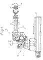
- Fig. 1 shows an appearance of a robot 10 according to a first embodiment of the present invention
- Figs. 2 to 9 illustrate distribution equipment in the robot 10.
- the robot 10 is a six-axis articulated robot, and is provided with a robot mechanism 10 including a base 12 and a manipulator 14 mounted on the base 12 in a movable manner.
- the robot mechanism 16 includes control axes, referred to as a J1 axis, a J2 axis, a J3 axis, a J4 axis, a J5 axis and a J6 axis in due order from the base 12 to a wrist portion 18 of the manipulator 14, and operates due to the driving action of motors of these control axes under the control of a control section (not shown).
- the operation modes of the respective control axes are shown by bi-directional arrows, in which the J1 axis is provided for a linear motion and the J2 to the J6 axes are provided for a rotating motion.
- distribution equipment 20 is provided for distributing various substances (such as electric current, air, inactive gas, water or paint) relating to power, energy, signals, information or materials, for the purpose of the driving control of electric motors in respective control axes in the robot mechanism 16, the driving control of an end-effector (not shown) attached to the wrist portion 18 of the manipulator 14, the use in the end-effector, the transfer of information to or from various sensors (not shown), and so on.
- the distribution equipment 20 includes an umbilical member 22 such as a cable or conduit incorporating therein a signal line or a material feeding line and a laying structure 24 arranged in the robot mechanism for suitably laying the umbilical member 22.
- the umbilical member 22 tends to have a relatively large change in the position and orientation thereof, between a first (or linearly moving) member operating in the J1 axis (e.g., a slider 26) and a second (or rotating) member operating in the J2 axis (e.g., a drum 28).
- the laying structure 24 of the distribution equipment 20 has a characteristic configuration, as described below, in a peripheral region of the J1 and the J2 axes.
- the distribution equipment according to the present invention should not be limited to the illustrated configuration but may be properly used for laying an umbilical member between two members movable relative to each other in a robot mechanism.
- the base 12 is provided with a pair of linear guides 32 respectively composed of linear rails 30, and the slider 26 is mounted on the linear guides 32 in a linearly movable manner.
- the operation of the slider 26 is controlled in the J1 axis (i.e., a linear motion control in the J1 axis).
- a driving system in the J1 axis including a servo-motor is not illustrated.
- An electric motor 34 is mounted on the slider 26 as a driving source in the J2 axis, and the drum 28 is attached to the slider 26 via a bearing unit 36.
- the output shaft of the electric motor 34 is connected to the drum 28 through a speed reduction unit 38, so that the drum 28 rotates due to the output of the electric motor 34 (i.e., a rotation control in the J2 axis).
- the laying structure 24 of the distribution equipment 20 is provided with a protective pipe 40 for protecting the umbilical member 22 in the vicinity of a rotary structure controlled in the J2 axis.
- the protective pipe 40 is fixedly attached to the drum 28 driven for rotation in the J2 axis, and extends generally parallel to a rotation axis of the drum.
- a first clamp member 42 is arranged to clamp the umbilical member 22 at a suitable position on the rotary structure in the J2 axis.
- the attaching position of the protective pipe 40 on the drum 28 is radially offset from the rotary center in the J2 axis.
- the protective pipe 40 moves in revolution, relative to the slider 26, along an orbit having a radius corresponding to an offset distance, over a rotation angle determined in the J2 axis and about the rotary center in the J2 axis, during the rotating operation in the J2 axis.
- an arcuate opening guide 44 extending in correspondence to a rotation angle range in the J2 axis is provided in the slider 26.
- the umbilical member 22 is directed from the base 12 to an inner upper position in the rotary structure in the J2 axis through the interior of the protective pipe 40, is clamped at this position by the first clamp member 42, and is further directed to operative members in the subsequent axes including the J3 axis.
- the protective pipe 40 is subjected to the above-described superimposed motion resulted from the linear and orbital motions and, therefore, the laying structure 24 of the distribution equipment 20 is provided with a characteristic configuration, as described below, to prevent the umbilical member 22 from being fully stretched by the above-described motion of the protective pipe 40 in the peripheral area of the J1 and the J2 axes.
- the laying structure 24 includes a slide rail 46 arranged in the slider 26 and a second movable clamp member 48 attached to the slide rail 46 in such a manner as to be movable along the extending direction thereof (as shown by an arrow T).
- the umbilical member 22 accommodated in the base 12 is suitably branched into some pieces at one end 22a thereof (a left end in Fig. 9) to be connected to a connector (not shown), extends inside the base 12 with a U-shaped turn, and is clamped by the movable clamp member 48 at an intermediate position on the way toward the protective pipe 40. Further, the umbilical member 22 is introduced from the movable clamp member 48 into the protective pipe 40 through a bottom opening thereof, and is clamped by the clamp member 42 arranged near the top opening of the protective pipe 40 as already described.
- the laying structure 24 further includes a connecting member 50 for mutually connecting the movable clamp member 48 and the drum 28 (particularly, the protective pipe 40) in a correlatively movable manner. More specifically, the connecting member 50 is fixedly attached at one end thereof to the movable clamp member 48 and, at the other end thereof, to a ring 52 provided rotatably about an axis 40a of the protective pipe 40 in a bottom region of the protective pipe 40.
- the connecting member 50 has a length slightly shorter than the corresponding length of the umbilical member 22 extending between the movable clamp member 48 and the ring 52.
- the connecting member 50 transmits a force (or a torque) generating due to the movement of the drum 28 (or a second member) relative to the slider 26 (or a first member) to the movable clamp member 48, as a stretching or compressive force, so as to move the movable clamp member 48 along the slide rail 46 on the slider 26.
- the connecting member 50 is made of a material having flexibility in relation, at least, to a bending mode.
- the connecting member 50 may have flexibility in relation to a torsion mode, as occasion demands.
- the connecting member 50 may have various forms, such as linear, flat or chain-like forms, and may also have a structure in which a plurality of links are connected to each other, provided that it has a desired flexibility and mechanical strength. In this regard, it is unfavorable that the connecting member 50 is easily stretchable by a tensile force.
- the connecting member 50 of a chain or link structure may require flexibility in its entirety, irrespective of whether the individual chain or link element thereof has flexibility.
- the connecting member 50 is pulled and stretched before the umbilical member 22 is fully stretched, so as to move the movable clamp member 48 toward the protective pipe 40. Therefore, the umbilical member 22 is not substantially subjected to a tensile force. In other words, a tensile force, which is otherwise applied to the umbilical member 22 if no connecting member 50 is used, would be mainly borne by the connecting member 50.
- the change in the orientation (or the slack) of the umbilical member 22 is suppressed during the rotating operation in the J2 axis, and the umbilical member 22 is thus prevented from being significantly rubbed with a peripheral member such as the protective pipe 40.
- the movable clamp member 48 moves smoothly along the slide rail 46 in a direction away from the protective pipe 40, in correspondence to the stiffness of both the connecting member 50 and the umbilical member 22. Thereby, the change in the orientation (or the slack) of the umbilical member 22 is suppressed.
- the movable clamp member 48 is designed to be supported on the slide rail 46 under a friction as low as possible, so as to be smoothly movable by a slight force.
- Figs. 10 to 12 show a peripheral structure of the J1 and the J2 axes in a robot according to a second embodiment of the present invention.
- This robot is provided with a basic structure identical to that of the robot 10 according to the first embodiment, and thus the corresponding components are denoted by common reference numerals and the explanation thereof is not repeated.
- a laying structure 24 of distribution equipment 20 in the second embodiment includes a support arm 54 pivotally attached to a slider 26, and a movable clamp member 48 supported in a rotatable manner at a distal end of the support arm 54.
- a pivot axis 54a of the support arm 54 on the slider 26 and a rotation axis 48a of the movable clamp member 48 on the support arm 54 are arranged in generally parallel to a rotation axis in the J2 axis at positions suitably apart from the latter.
- the laying structure 24 further includes a connecting member 50 connecting the movable clamp member 48 to a drum 28 (particularly, a protective pipe 40) in a correlatively movable manner.
- the connecting member 50 is fixedly attached at one end thereof to the movable clamp member 48 and at the other end thereof to the clamp member 42 arranged near the top opening of the protective pipe 40.
- the connecting member 50 has a length slightly shorter than the corresponding length of the umbi.lical member 22 extending between the movable clamp member 48 and the clamp member 42.
- the connecting member 50 transmits a force (or a torque) generated due to the movement of the drum 28 (or a second member) relative to the slider 26 (or a first member) to the movable clamp member 48, as a stretching or compressive force, so as to move the movable clamp member 48 on the slider 26 while accompanied with the pivoting motion of the support arm 54.
- the above-described configuration is one which adopts the support arm 54 pivotingly shiftable on the slider 26, instead of the slide rail 46 in the first embodiment, and thus the movable clamp member 48 moves in a direction toward or away from the drum 28 (particularly, the protective pipe 40) while rotating relative to the slider 26 by a force transmitted through the connecting member 50.
- the connecting member 50 having flexibility in relation to a torsion mode is used, because a torsion force is applied to the connecting member 50.
- a tensile force is not substantially applied to the umbilical member 22 but is mainly applied to the connecting member 50 when the distance between the protective pipe 40 and the movable clamp member 48 increases due to the rotating operation in the J2 axis.
- the movable clamp member 48 smoothly moves in a direction away from the protective pipe 40, in correspondence to the stiffness of both the connecting member 50 and the umbilical member 22, while accompanying with the pivoting motion of the support arm 54.
Landscapes
- Engineering & Computer Science (AREA)
- Robotics (AREA)
- Mechanical Engineering (AREA)
- Manipulator (AREA)
- Electric Cable Arrangement Between Relatively Moving Parts (AREA)
Abstract
Description
- The present invention relates generally to a robot and, more particularly, to an improvement in distribution equipment for supplying power, signals, materials or others to a manipulator.
- In a robot or, especially, an industrial robot, distribution equipment is provided for distributing or communicating various substances (such as electric current, air, inactive gas, water or paint) relating to power, energy, signals, information or materials, for the purpose of the driving control of electric motors in respective control axes in a manipulator, the driving control of an end-effector, the use in the end-effector, the transfer of information to or from various sensors, and so on. In this type of distribution equipment, an umbilical member, such as a cable or a conduit, incorporating signal lines or material feeding lines therein is generally used, and a laying structure is provided, in a robot mechanism including a manipulator, for suitably laying the umbilical member.
- In the above-described distribution equipment for the robot, it is required that the umbilical member is not entangled with the manipulator or stretched during the operation of the manipulator. To this end, the conventional laying structure, provided in the robot mechanism, includes a clamp member for clamping the umbilical member at a suitable intermediate position, while providing the umbilical member with a desired slack. In this regard, as the umbilical member is generally laid out between a plurality of members movable relative to each other and across a joint in the manipulator, it is necessary to properly select a position at which the umbilical member is clamped.
- For example, in the case where the clamp member is fixedly provided in the robot mechanism, the clamp member is arranged at a position permitting the sufficient slack of the umbilical member, so that the umbilical member is not fully stretched during a period when the plural members in the robot mechanism are moving relatively. In this case, the reduction in outside dimension of the robot mechanism may be disturbed for the purpose of allowing the larger slack of the umbilical member. Contrary to this, in the case where the clamp member is movably arranged in the robot mechanism, the clamp member can suitably move in correspondence to the relative movement of the plural members in the robot mechanism, whereby it is possible to minimize the slack of the umbilical member between clamped positions and thus to exclude an influence on the outside dimension of the robot mechanism. In this arrangement, however, as the movable clamp member moves under the application of a stretching force to the umbilical member, which results from the relative movement of the plural members in the robot mechanism, the umbilical member may be damaged by the stretching force.
- It is an object of the present invention to provide a robot including distribution equipment for laying an umbilical member between mutually movable plural members in a robot mechanism, wherein the distribution equipment is able to prevent the umbilical member from being damaged during the operation of the robot mechanism and thus to increase the life of the umbilical member, without influencing the outside dimension of the robot mechanism.
- To accomplish the above object, the present invention provides a robot comprising a robot mechanism including a first member and a second member, the first member and the second member being movable relative to each other; an umbilical member laid in the robot mechanism and extending between the first member and the second member; a clamp member movably provided in the first member to clamp the umbilical member; and a connecting member for connecting the clamp member to the second member in a correlatively movable manner, the connecting member transmitting a force generating due to a movement of the second member relative to the first member, to move the clamp member in the first member.
- In the robot as described above, it is preferred that the connecting member has flexibility.
- Also, the movement of the second member for generating the force may be a rotating movement relative to the first member.
- The clamp member may be provided in the first member in a linearly movable manner.
- Alternatively, the clamp member may be provided in the first member in a rotatable manner.
- In this arrangement, the robot may further comprise a support member rotatably supporting the clamp member, the support member being pivotably attached to the first member.
- The above and other objects, features and advantages of the present invention will become more apparent from the following description of preferred embodiments in connection with the accompanying drawings, wherein:
- Fig. 1 is a diagrammatic front view showing the appearance of a robot according to a first embodiment of the present invention, and illustrating the operation modes of respective control axes of a robot mechanism;
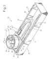
- Fig. 2 is a diagrammatic perspective view showing a peripheral structure of J1 and J2 axes in the robot of Fig. 1;
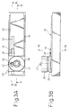
- Fig. 3A is a plan view showing the structure of Fig. 2;
- Fig. 3B is a front view showing the structure of Fig. 2;
- Fig. 4 is a sectional view taken along a line IV-IV in Fig. 3A; Fig. 5 is an enlarged perspective view showing a part of the structure of Fig. 2 with a rotary member of the J2 axis being omitted:
- Fig. 6 is a perspective view showing a slider and a protective pipe in an exposed state with a driving structure of the J2 axis in the structure of Fig. 5 being omitted;
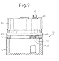
- Fig. 7 is a sectional view taken along a line VII-VII in Fig. 3B;
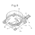
- Fig. 8 is a perspective view showing a slider in the structure of Fig. 2 from the bottom side thereof to clearly show a connecting member;
- Fig. 9 is a sectional view taken along a line IX-IX in Fig. 3A;
- Fig. 10 is a sectional view, corresponding to Fig. 7, showing a peripheral structure of the J1 and the J2 axes in a robot, according to a second embodiment of the present invention;
- Fig. 11 is a perspective view, corresponding to Fig. 8, showing the structure of Fig. 10; and
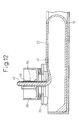
- Fig. 12 is a sectional view, corresponding to Fig. 9, showing the structure of Fig. 10.
-
- The embodiments of the present invention are described below in detail, with reference to the accompanying drawings. In the drawings, the same or similar components are denoted by common reference numerals.
- Referring to the drawings, Fig. 1 shows an appearance of a
robot 10 according to a first embodiment of the present invention, and Figs. 2 to 9 illustrate distribution equipment in therobot 10. As shown in Fig. 1, therobot 10 is a six-axis articulated robot, and is provided with arobot mechanism 10 including abase 12 and amanipulator 14 mounted on thebase 12 in a movable manner. Therobot mechanism 16 includes control axes, referred to as a J1 axis, a J2 axis, a J3 axis, a J4 axis, a J5 axis and a J6 axis in due order from thebase 12 to awrist portion 18 of themanipulator 14, and operates due to the driving action of motors of these control axes under the control of a control section (not shown). The operation modes of the respective control axes are shown by bi-directional arrows, in which the J1 axis is provided for a linear motion and the J2 to the J6 axes are provided for a rotating motion. - In the
robot 10,distribution equipment 20 is provided for distributing various substances (such as electric current, air, inactive gas, water or paint) relating to power, energy, signals, information or materials, for the purpose of the driving control of electric motors in respective control axes in therobot mechanism 16, the driving control of an end-effector (not shown) attached to thewrist portion 18 of themanipulator 14, the use in the end-effector, the transfer of information to or from various sensors (not shown), and so on. As shown in Fig. 2, thedistribution equipment 20 includes anumbilical member 22 such as a cable or conduit incorporating therein a signal line or a material feeding line and alaying structure 24 arranged in the robot mechanism for suitably laying theumbilical member 22. - In the
robot 10 having the above-described configuration, theumbilical member 22 tends to have a relatively large change in the position and orientation thereof, between a first (or linearly moving) member operating in the J1 axis (e.g., a slider 26) and a second (or rotating) member operating in the J2 axis (e.g., a drum 28). Accordingly, thelaying structure 24 of thedistribution equipment 20 has a characteristic configuration, as described below, in a peripheral region of the J1 and the J2 axes. In this regard, the distribution equipment according to the present invention should not be limited to the illustrated configuration but may be properly used for laying an umbilical member between two members movable relative to each other in a robot mechanism. - In the
robot mechanism 16, thebase 12 is provided with a pair oflinear guides 32 respectively composed oflinear rails 30, and theslider 26 is mounted on thelinear guides 32 in a linearly movable manner. The operation of theslider 26 is controlled in the J1 axis (i.e., a linear motion control in the J1 axis). In this regard, a driving system in the J1 axis including a servo-motor is not illustrated. Anelectric motor 34 is mounted on theslider 26 as a driving source in the J2 axis, and thedrum 28 is attached to theslider 26 via abearing unit 36. The output shaft of theelectric motor 34 is connected to thedrum 28 through aspeed reduction unit 38, so that thedrum 28 rotates due to the output of the electric motor 34 (i.e., a rotation control in the J2 axis). - The
laying structure 24 of thedistribution equipment 20 is provided with aprotective pipe 40 for protecting theumbilical member 22 in the vicinity of a rotary structure controlled in the J2 axis. Theprotective pipe 40 is fixedly attached to thedrum 28 driven for rotation in the J2 axis, and extends generally parallel to a rotation axis of the drum. In the vicinity of the top opening of theprotective pipe 40, afirst clamp member 42 is arranged to clamp theumbilical member 22 at a suitable position on the rotary structure in the J2 axis. In this regard, as shown in Figs. 3A to 4, as theelectric motor 34 and thereduction unit 38 are disposed near the rotary center in the J2 axis, the attaching position of theprotective pipe 40 on thedrum 28 is radially offset from the rotary center in the J2 axis. - According to the above-described offset arrangement, the
protective pipe 40 moves in revolution, relative to theslider 26, along an orbit having a radius corresponding to an offset distance, over a rotation angle determined in the J2 axis and about the rotary center in the J2 axis, during the rotating operation in the J2 axis. In order to allow this orbital motion, as shown in Figs. 5 and 6, anarcuate opening guide 44 extending in correspondence to a rotation angle range in the J2 axis is provided in theslider 26. Thus, theprotective pipe 40 moves along theopening guide 44 when the J2 axis rotates. Consequently, during a period when the J1 and the J2 axes operate simultaneously with each other, theprotective pipe 40 generates such a motion that the linear motion of theslider 26 is superimposed with the above-described orbital motion. - In this way, the
umbilical member 22 is directed from the base 12 to an inner upper position in the rotary structure in the J2 axis through the interior of theprotective pipe 40, is clamped at this position by thefirst clamp member 42, and is further directed to operative members in the subsequent axes including the J3 axis. In this connection, it is expected that theprotective pipe 40 is subjected to the above-described superimposed motion resulted from the linear and orbital motions and, therefore, the layingstructure 24 of thedistribution equipment 20 is provided with a characteristic configuration, as described below, to prevent theumbilical member 22 from being fully stretched by the above-described motion of theprotective pipe 40 in the peripheral area of the J1 and the J2 axes. - As shown in Figs. 7 to 9, the laying
structure 24 includes aslide rail 46 arranged in theslider 26 and a secondmovable clamp member 48 attached to theslide rail 46 in such a manner as to be movable along the extending direction thereof (as shown by an arrow T). Theumbilical member 22 accommodated in thebase 12 is suitably branched into some pieces at oneend 22a thereof (a left end in Fig. 9) to be connected to a connector (not shown), extends inside the base 12 with a U-shaped turn, and is clamped by themovable clamp member 48 at an intermediate position on the way toward theprotective pipe 40. Further, theumbilical member 22 is introduced from themovable clamp member 48 into theprotective pipe 40 through a bottom opening thereof, and is clamped by theclamp member 42 arranged near the top opening of theprotective pipe 40 as already described. - The laying
structure 24 further includes a connectingmember 50 for mutually connecting themovable clamp member 48 and the drum 28 (particularly, the protective pipe 40) in a correlatively movable manner. More specifically, the connectingmember 50 is fixedly attached at one end thereof to themovable clamp member 48 and, at the other end thereof, to aring 52 provided rotatably about anaxis 40a of theprotective pipe 40 in a bottom region of theprotective pipe 40. The connectingmember 50 has a length slightly shorter than the corresponding length of theumbilical member 22 extending between themovable clamp member 48 and thering 52. Thereby, the connectingmember 50 transmits a force (or a torque) generating due to the movement of the drum 28 (or a second member) relative to the slider 26 (or a first member) to themovable clamp member 48, as a stretching or compressive force, so as to move themovable clamp member 48 along theslide rail 46 on theslider 26. - Preferably, the connecting
member 50 is made of a material having flexibility in relation, at least, to a bending mode. Also, the connectingmember 50 may have flexibility in relation to a torsion mode, as occasion demands. The connectingmember 50 may have various forms, such as linear, flat or chain-like forms, and may also have a structure in which a plurality of links are connected to each other, provided that it has a desired flexibility and mechanical strength. In this regard, it is unfavorable that the connectingmember 50 is easily stretchable by a tensile force. Also, the connectingmember 50 of a chain or link structure may require flexibility in its entirety, irrespective of whether the individual chain or link element thereof has flexibility. - According to the above-described configuration, when the distance between the
protective pipe 40 and themovable clamp member 48 increases due to the rotating operation in the J2 axis, the connectingmember 50 is pulled and stretched before theumbilical member 22 is fully stretched, so as to move themovable clamp member 48 toward theprotective pipe 40. Therefore, theumbilical member 22 is not substantially subjected to a tensile force. In other words, a tensile force, which is otherwise applied to theumbilical member 22 if no connectingmember 50 is used, would be mainly borne by the connectingmember 50. As theumbilical member 22 is not subjected to the tensile force, the change in the orientation (or the slack) of theumbilical member 22 is suppressed during the rotating operation in the J2 axis, and theumbilical member 22 is thus prevented from being significantly rubbed with a peripheral member such as theprotective pipe 40. - Also, when the
protective pipe 40 is shifted toward themovable clamp member 48 by the rotating operation in the J2 axis, themovable clamp member 48 moves smoothly along theslide rail 46 in a direction away from theprotective pipe 40, in correspondence to the stiffness of both the connectingmember 50 and theumbilical member 22. Thereby, the change in the orientation (or the slack) of theumbilical member 22 is suppressed. From this viewpoint, it is preferred that themovable clamp member 48 is designed to be supported on theslide rail 46 under a friction as low as possible, so as to be smoothly movable by a slight force. Thus, according to therobot 10 having the above configuration, it is possible to prevent theumbilical member 22 from being damaged during the operation of the robot mechanism 16 (particularly, in the J2 axis), and to increase the life of theumbilical member 22. - Figs. 10 to 12 show a peripheral structure of the J1 and the J2 axes in a robot according to a second embodiment of the present invention. This robot is provided with a basic structure identical to that of the
robot 10 according to the first embodiment, and thus the corresponding components are denoted by common reference numerals and the explanation thereof is not repeated. - A laying
structure 24 ofdistribution equipment 20 in the second embodiment includes asupport arm 54 pivotally attached to aslider 26, and amovable clamp member 48 supported in a rotatable manner at a distal end of thesupport arm 54. Apivot axis 54a of thesupport arm 54 on theslider 26 and arotation axis 48a of themovable clamp member 48 on thesupport arm 54 are arranged in generally parallel to a rotation axis in the J2 axis at positions suitably apart from the latter. - The laying
structure 24 further includes a connectingmember 50 connecting themovable clamp member 48 to a drum 28 (particularly, a protective pipe 40) in a correlatively movable manner. The connectingmember 50 is fixedly attached at one end thereof to themovable clamp member 48 and at the other end thereof to theclamp member 42 arranged near the top opening of theprotective pipe 40. The connectingmember 50 has a length slightly shorter than the corresponding length of the umbi.licalmember 22 extending between themovable clamp member 48 and theclamp member 42. Thereby, the connectingmember 50 transmits a force (or a torque) generated due to the movement of the drum 28 (or a second member) relative to the slider 26 (or a first member) to themovable clamp member 48, as a stretching or compressive force, so as to move themovable clamp member 48 on theslider 26 while accompanied with the pivoting motion of thesupport arm 54. - The above-described configuration is one which adopts the
support arm 54 pivotingly shiftable on theslider 26, instead of theslide rail 46 in the first embodiment, and thus themovable clamp member 48 moves in a direction toward or away from the drum 28 (particularly, the protective pipe 40) while rotating relative to theslider 26 by a force transmitted through the connectingmember 50. In this regard, in the second embodiment, the connectingmember 50 having flexibility in relation to a torsion mode is used, because a torsion force is applied to the connectingmember 50. - According to the above-described configuration, in the same manner as in the first embodiment, a tensile force is not substantially applied to the
umbilical member 22 but is mainly applied to the connectingmember 50 when the distance between theprotective pipe 40 and themovable clamp member 48 increases due to the rotating operation in the J2 axis. Also, when theprotective pipe 40 is shifted toward themovable clamp member 48 by the rotating operation in the J2 axis, themovable clamp member 48 smoothly moves in a direction away from theprotective pipe 40, in correspondence to the stiffness of both the connectingmember 50 and theumbilical member 22, while accompanying with the pivoting motion of thesupport arm 54. Thus, according to the robot of the second embodiment, it is possible to prevent theumbilical member 22 from being damaged during the operation of the robot mechanism 16 (particularly, in the J2 axis), and to increase the life of theumbilical member 22. - While the invention has been described with reference to specific preferred embodiments, it will be understood by those skilled in the art that various changes and modifications may be made thereto without departing from the spirit and scope of the following claims.
Claims (6)
- A robot comprising:a robot mechanism including a first member and a second member, said first member and said second member being movable relative to each other;an umbilical member laid in said robot mechanism and extending between said first member and said second member;a clamp member movably provided in said first member to clamp said umbilical member; anda connecting member for connecting said clamp member to said second member in a correlatively movable manner, said connecting member transmitting a force generating due to a movement of said second member relative to said first member, to move said clamp member in said first member.
- A robot as set forth in claim 1, wherein said connecting member has flexibility.
- A robot as set forth in claim 1, wherein said movement of said second member for generating said force is a rotating movement relative to said first member.
- A robot as set forth in claim 1, wherein said clamp member is provided in said first member in a linearly movable manner.
- A robot as set forth in claim 1, wherein said clamp member is provided in said first member in a rotatable manner.
- A robot as set forth in claim 5, further comprising a support member rotatably supporting said clamp member, said support member being pivotably attached to said first member.
Applications Claiming Priority (2)
| Application Number | Priority Date | Filing Date | Title |
|---|---|---|---|
| JP2003346103A JP3830481B2 (en) | 2003-10-03 | 2003-10-03 | Industrial robot |
| JP2003346103 | 2003-10-03 |
Publications (1)
| Publication Number | Publication Date |
|---|---|
| EP1520661A1 true EP1520661A1 (en) | 2005-04-06 |
Family
ID=34309171
Family Applications (1)
| Application Number | Title | Priority Date | Filing Date |
|---|---|---|---|
| EP04023451A Withdrawn EP1520661A1 (en) | 2003-10-03 | 2004-10-01 | Cable laying structure with clamping means for a robot |
Country Status (3)
| Country | Link |
|---|---|
| US (1) | US7464623B2 (en) |
| EP (1) | EP1520661A1 (en) |
| JP (1) | JP3830481B2 (en) |
Cited By (5)
| Publication number | Priority date | Publication date | Assignee | Title |
|---|---|---|---|---|
| EP1741523A3 (en) * | 2005-07-07 | 2007-12-26 | Fanuc Ltd | Industrial robot with a cable harness |
| DE102007018543A1 (en) * | 2007-04-17 | 2008-10-23 | Philipp, Steffen | Device for guiding supply lines along the structure of an industrial robot |
| EP2695705A1 (en) * | 2012-08-09 | 2014-02-12 | WFL Millturn Technologies GmbH & Co. KG | Machine tool with energy supply line |
| CN105014681A (en) * | 2015-08-10 | 2015-11-04 | 苏州驱指自动化科技有限公司 | Multifunctional adapter plate |
| EP3592512B1 (en) * | 2017-03-06 | 2022-09-21 | Robotautomation Svenska AB | An industrial robot and a device for transferring media from the robot to a tool |
Families Citing this family (14)
| Publication number | Priority date | Publication date | Assignee | Title |
|---|---|---|---|---|
| JP4391984B2 (en) | 2005-12-19 | 2009-12-24 | 富士通株式会社 | Cable transport mechanism and library device |
| US7677129B2 (en) * | 2007-09-28 | 2010-03-16 | Intuitive Surgical, Inc. | Multiaxis counterbalance and positioning system using a spatial linkage |
| JP2009119565A (en) * | 2007-11-15 | 2009-06-04 | Denso Wave Inc | Robot |
| DE102009010953A1 (en) | 2009-02-27 | 2010-09-02 | Dürr Systems GmbH | Robots, in particular painting robots |
| CN103085082B (en) * | 2011-11-04 | 2015-10-14 | 鸿富锦精密工业(深圳)有限公司 | Robot arm |
| ITTO20120425A1 (en) * | 2012-05-11 | 2013-11-12 | Dalmec Spa | BALANCED PNEUMATIC MANIPULATOR |
| GB2502611B (en) * | 2012-06-01 | 2017-03-15 | Tidal Generation Ltd | Connection systems |
| DE102013006244A1 (en) * | 2013-04-11 | 2014-10-16 | Volkswagen Aktiengesellschaft | Arrangement of an industrial robot for handling, assembly or processing of workpieces |
| JP5850964B2 (en) * | 2014-02-19 | 2016-02-03 | ファナック株式会社 | Robot traveling device having cable track, robot system, and processing system |
| CN104084532B (en) * | 2014-07-03 | 2016-03-23 | 浙江汉声精密机械有限公司 | A kind of power transmission device of resin sand production line |
| JP6054932B2 (en) * | 2014-10-14 | 2016-12-27 | ファナック株式会社 | Joint structure capable of optimizing the length margin of the striatum, and industrial robot equipped with the joint structure |
| JP6506195B2 (en) * | 2016-03-09 | 2019-04-24 | ファナック株式会社 | Rotary axis module and articulated robot |
| DE102020119499A1 (en) | 2020-07-23 | 2022-01-27 | Beckhoff Automation Gmbh | Driven linear axis and industrial robots |
| CN111969394B (en) * | 2020-08-17 | 2021-12-21 | 乐清市宇凯线缆有限公司 | Automatic forming and connecting process for electric appliance wire harness |
Citations (3)
| Publication number | Priority date | Publication date | Assignee | Title |
|---|---|---|---|---|
| JPS6339416A (en) | 1986-08-01 | 1988-02-19 | 松下電器産業株式会社 | Cable supporter of industrial robot |
| US5816107A (en) * | 1995-11-20 | 1998-10-06 | Tokico Ltd. | Joint for industrial robot |
| DE29720048U1 (en) * | 1997-11-12 | 1999-03-18 | Dinse GmbH, 22041 Hamburg | Arc welding device |
Family Cites Families (4)
| Publication number | Priority date | Publication date | Assignee | Title |
|---|---|---|---|---|
| DE19816949A1 (en) * | 1998-04-17 | 1999-10-21 | Kuka Roboter Gmbh | robot |
| JP2003305684A (en) * | 2002-04-15 | 2003-10-28 | Fanuc Ltd | Linear member placement structure in relative rotation mechanism |
| JP2005144610A (en) * | 2003-11-17 | 2005-06-09 | Fanuc Ltd | Sensor cable wiring processing structure |
| JP3987845B2 (en) * | 2004-08-13 | 2007-10-10 | ファナック株式会社 | Striated structure of industrial robot |
-
2003
- 2003-10-03 JP JP2003346103A patent/JP3830481B2/en not_active Expired - Fee Related
-
2004
- 2004-09-30 US US10/953,278 patent/US7464623B2/en not_active Expired - Fee Related
- 2004-10-01 EP EP04023451A patent/EP1520661A1/en not_active Withdrawn
Patent Citations (3)
| Publication number | Priority date | Publication date | Assignee | Title |
|---|---|---|---|---|
| JPS6339416A (en) | 1986-08-01 | 1988-02-19 | 松下電器産業株式会社 | Cable supporter of industrial robot |
| US5816107A (en) * | 1995-11-20 | 1998-10-06 | Tokico Ltd. | Joint for industrial robot |
| DE29720048U1 (en) * | 1997-11-12 | 1999-03-18 | Dinse GmbH, 22041 Hamburg | Arc welding device |
Cited By (6)
| Publication number | Priority date | Publication date | Assignee | Title |
|---|---|---|---|---|
| EP1741523A3 (en) * | 2005-07-07 | 2007-12-26 | Fanuc Ltd | Industrial robot with a cable harness |
| DE102007018543A1 (en) * | 2007-04-17 | 2008-10-23 | Philipp, Steffen | Device for guiding supply lines along the structure of an industrial robot |
| DE102007018543B4 (en) * | 2007-04-17 | 2009-02-26 | Philipp, Steffen | Device for guiding supply lines along the structure of an industrial robot |
| EP2695705A1 (en) * | 2012-08-09 | 2014-02-12 | WFL Millturn Technologies GmbH & Co. KG | Machine tool with energy supply line |
| CN105014681A (en) * | 2015-08-10 | 2015-11-04 | 苏州驱指自动化科技有限公司 | Multifunctional adapter plate |
| EP3592512B1 (en) * | 2017-03-06 | 2022-09-21 | Robotautomation Svenska AB | An industrial robot and a device for transferring media from the robot to a tool |
Also Published As
| Publication number | Publication date |
|---|---|
| JP3830481B2 (en) | 2006-10-04 |
| US20050072261A1 (en) | 2005-04-07 |
| JP2005111585A (en) | 2005-04-28 |
| US7464623B2 (en) | 2008-12-16 |
Similar Documents
| Publication | Publication Date | Title |
|---|---|---|
| US7464623B2 (en) | Distribution equipment for robot | |
| US4712971A (en) | Control arm assembly | |
| CA1210421A (en) | Split-ball type wrist and manipulator assembly for robot | |
| EP1083030B1 (en) | Robot with devices for guiding a wiring member and/or a tubing member | |
| US7281447B2 (en) | Articulated mechanism comprising a cable reduction gear for use in a robot arm | |
| KR930002624B1 (en) | Industrial robot equipped with a cable extending means | |
| EP1625920B1 (en) | Managing structure for umbilical member of industrial robot | |
| US8511197B2 (en) | Robot arm assembly | |
| US20080229862A1 (en) | Wire drive mechanism, robot arm mechanism, and robot | |
| JP2004216535A (en) | Articulated robot | |
| WO2003051583A1 (en) | Multi-finger hand device | |
| CN110311344B (en) | Cable clamp and robot | |
| JPH10175188A (en) | Robot structure | |
| CA2860487A1 (en) | Serially jointed manipulator arm | |
| JP4315720B2 (en) | Cable guides for joints such as robots | |
| JP6923489B2 (en) | Horizontal articulated robot | |
| EP0658404B1 (en) | Industrial robot | |
| US6336374B1 (en) | Device for relative displacement of two elements | |
| US4218166A (en) | Guide device for multi-axis manipulator | |
| JP2001150382A (en) | Guide device of wiring member and/or piping member, and robot having the same | |
| JPS6263073A (en) | Joint structure of rotary arm | |
| JP4270041B2 (en) | Robot wrist device and robot equipped with the same | |
| EP0997239A2 (en) | Structure of cable and/or pipe arrangement applied in parallel link mechanism | |
| JP2006198703A (en) | Arm drive device for humanoid robot | |
| JP2006522290A (en) | Drive unit used for joint arm |
Legal Events
| Date | Code | Title | Description |
|---|---|---|---|
| PUAI | Public reference made under article 153(3) epc to a published international application that has entered the european phase |
Free format text: ORIGINAL CODE: 0009012 |
|
| AK | Designated contracting states |
Kind code of ref document: A1 Designated state(s): AT BE BG CH CY CZ DE DK EE ES FI FR GB GR HU IE IT LI LU MC NL PL PT RO SE SI SK TR |
|
| AX | Request for extension of the european patent |
Extension state: AL HR LT LV MK |
|
| 17P | Request for examination filed |
Effective date: 20050228 |
|
| AKX | Designation fees paid |
Designated state(s): DE |
|
| 17Q | First examination report despatched |
Effective date: 20100818 |
|
| RAP1 | Party data changed (applicant data changed or rights of an application transferred) |
Owner name: FANUC CORPORATION |
|
| GRAP | Despatch of communication of intention to grant a patent |
Free format text: ORIGINAL CODE: EPIDOSNIGR1 |
|
| STAA | Information on the status of an ep patent application or granted ep patent |
Free format text: STATUS: THE APPLICATION IS DEEMED TO BE WITHDRAWN |
|
| 18D | Application deemed to be withdrawn |
Effective date: 20110922 |