EP1520650A1 - System for cooling a liquid-cooled welding device - Google Patents
System for cooling a liquid-cooled welding device Download PDFInfo
- Publication number
- EP1520650A1 EP1520650A1 EP04019894A EP04019894A EP1520650A1 EP 1520650 A1 EP1520650 A1 EP 1520650A1 EP 04019894 A EP04019894 A EP 04019894A EP 04019894 A EP04019894 A EP 04019894A EP 1520650 A1 EP1520650 A1 EP 1520650A1
- Authority
- EP
- European Patent Office
- Prior art keywords
- liquid
- torch head
- head body
- welding device
- torch
- Prior art date
- Legal status (The legal status is an assumption and is not a legal conclusion. Google has not performed a legal analysis and makes no representation as to the accuracy of the status listed.)
- Granted
Links
- 238000003466 welding Methods 0.000 title claims abstract description 74
- 238000001816 cooling Methods 0.000 title claims abstract description 32
- 239000007788 liquid Substances 0.000 claims abstract description 85
- 238000012546 transfer Methods 0.000 claims abstract description 6
- 239000000110 cooling liquid Substances 0.000 claims description 29
- 230000005611 electricity Effects 0.000 claims description 12
- 239000012530 fluid Substances 0.000 claims description 2
- 239000007789 gas Substances 0.000 description 25
- 238000000034 method Methods 0.000 description 10
- 239000004020 conductor Substances 0.000 description 3
- 239000012809 cooling fluid Substances 0.000 description 3
- WFKWXMTUELFFGS-UHFFFAOYSA-N tungsten Chemical compound [W] WFKWXMTUELFFGS-UHFFFAOYSA-N 0.000 description 3
- 229910052721 tungsten Inorganic materials 0.000 description 3
- 239000010937 tungsten Substances 0.000 description 3
- BQCADISMDOOEFD-UHFFFAOYSA-N Silver Chemical group [Ag] BQCADISMDOOEFD-UHFFFAOYSA-N 0.000 description 2
- 230000008901 benefit Effects 0.000 description 2
- 238000013461 design Methods 0.000 description 2
- 238000011161 development Methods 0.000 description 2
- 238000004519 manufacturing process Methods 0.000 description 2
- 239000000463 material Substances 0.000 description 2
- 238000012986 modification Methods 0.000 description 2
- 230000004048 modification Effects 0.000 description 2
- 230000001105 regulatory effect Effects 0.000 description 2
- RYGMFSIKBFXOCR-UHFFFAOYSA-N Copper Chemical compound [Cu] RYGMFSIKBFXOCR-UHFFFAOYSA-N 0.000 description 1
- 229910000990 Ni alloy Inorganic materials 0.000 description 1
- FRRKSHPWTFGWIV-UHFFFAOYSA-N [Ni].[Cu].[Pb] Chemical compound [Ni].[Cu].[Pb] FRRKSHPWTFGWIV-UHFFFAOYSA-N 0.000 description 1
- 238000005219 brazing Methods 0.000 description 1
- 229910052802 copper Inorganic materials 0.000 description 1
- 239000010949 copper Substances 0.000 description 1
- 230000007423 decrease Effects 0.000 description 1
- 238000010891 electric arc Methods 0.000 description 1
- 230000001939 inductive effect Effects 0.000 description 1
- 239000011261 inert gas Substances 0.000 description 1
- 238000002844 melting Methods 0.000 description 1
- 230000008018 melting Effects 0.000 description 1
- 229910052751 metal Inorganic materials 0.000 description 1
- 239000002184 metal Substances 0.000 description 1
- 238000005476 soldering Methods 0.000 description 1
- 239000010935 stainless steel Substances 0.000 description 1
- 229910001220 stainless steel Inorganic materials 0.000 description 1
Images



Classifications
-
- B—PERFORMING OPERATIONS; TRANSPORTING
- B23—MACHINE TOOLS; METAL-WORKING NOT OTHERWISE PROVIDED FOR
- B23K—SOLDERING OR UNSOLDERING; WELDING; CLADDING OR PLATING BY SOLDERING OR WELDING; CUTTING BY APPLYING HEAT LOCALLY, e.g. FLAME CUTTING; WORKING BY LASER BEAM
- B23K9/00—Arc welding or cutting
- B23K9/24—Features related to electrodes
- B23K9/28—Supporting devices for electrodes
- B23K9/285—Cooled electrode holders
Definitions
- the present invention relates generally to the field of arc welding, and more particularly to the field of liquid-cooled arc welding torches.
- Arc welding is a welding process in which an electric current is used to produce localized melting in a work piece.
- arc welding processes There are many different types of arc welding processes.
- TIG welding is a type of arc welding process in which an electric arc is maintained between a welding implement, such as a hand-held welding torch, and a metal work piece.
- the welding implement includes a cylindrical electrode coupled to a torch head.
- the arc is produced by electricity that flows between the electrode and the work piece.
- the electrode is comprised of tungsten.
- the electricity for the arc welding process is provided by a power source coupled to the torch head of the welding implement by a power cable.
- the electricity flowing through the torch head may produce a substantial amount of heat.
- the electricity flowing through the electrode and the work piece may produce heat that is transferred to the torch head.
- the heat introduced into the torch head may damage the components of the torch.
- the heat may make the torch difficult to hold.
- the amount of heat produced is a function of the current flowing through the torch.
- the torches may be air-cooled at low current levels. However, the ability of air-cooling to sufficiently cool the torch decreases as the amount of current flowing through the torch increases. Consequently, liquid-cooled welding torches have been developed to remove a greater amount of the heat from within the torch head, thereby enabling the torch to be operated at higher current levels.
- a liquid-cooling unit is coupled to the welding torch to supply a flow of liquid to cool the welding torch.
- the cooling unit also removes the heat transferred to the liquid from the welding torch.
- liquid-cooling units add a significant expense to the system.
- a lower capacity liquid-cooling unit is less expensive that a larger capacity liquid-cooling unit.
- the welding system 10 comprises a welding machine 12, a liquid-cooled TIG welding torch assembly 14, and a liquid cooling unit 16.
- the welding machine 12 is operable to provide the power to enable a user to weld with the welding torch assembly 14.
- the liquid cooling unit 16 is operable to provide a flow of liquid to remove heat from the welding torch assembly 14 produced during welding operations.
- a flexible gas hose 18 is coupled between the welding machine 12 and the torch assembly 14 to enable the welding machine 12 to supply a shield gas 20 to the welding torch assembly 14.
- a liquid hose 22 is coupled between the liquid cooling unit 16 and the welding torch assembly 14 to enable the liquid cooling unit 16 to provide a supply of cooling liquid 24 to the torch assembly 14.
- a power cable 26 is coupled between the torch assembly 14 and the welding machine 12. The power cable 26 provides a flow path for heated cooling liquid 28 to flow from the torch assembly 14, as well as to provide a path for electric current 30 to flow to the torch assembly 14 from the welding machine 12.
- the power cable 26 has a connector 32 that is connected to the welding machine 12 to electrically couple the torch assembly 14 to the welding machine 12.
- a liquid hose 34 is coupled to the connector 32 to provide a return path for the heated cooling liquid 28 to flow back to the liquid cooling unit 16.
- the illustrated system 10 comprises a clamp 36 and a return cable 38 for electrically connecting a work piece to the welding machine 12.
- a regulated gas cylinder 40 and hose 42 are provided to supply gas 20 to the welding machine 12.
- another source of gas 20 may be used.
- the regulated gas cylinder 40 or some other source of gas may be connected directly to the torch assembly 14.
- the liquid-cooled welding torch assembly 14 is adapted to conduct electric current 30 to an electrode 44 secured to the torch assembly 14 and to direct the flow of gas 20 from the torch assembly 14.
- the liquid-cooled welding torch assembly 14 has a torch head 46 for receiving the electrode 44 and gas 20.
- the electrode 44 is disposed through one end of the torch head 46.
- a back cap 48 is provided to seal the opposite end of the torch head 46.
- the welding torch assembly 14 also comprises a nozzle 50 that is coupled to the torch head 46 to direct the gas 20 to flow from the welding torch assembly 14 in a desired pattern.
- a handle 51 is provided on the welding torch assembly 14 to enable a user to direct movement of the electrode 44.
- the liquid-cooled welding torch assembly 14 comprises a gas tube 52, a liquid supply tube 54, and a liquid return tube 56.
- An insulated cover may be molded over the welding torch assembly 14 to electrically insulate the torch head 46, the gas tube 52, the liquid supply tube 54, and the liquid return tube 56
- the return tube 56 couples electricity 30 to the torch head 46.
- the liquid return tube 56 has a fitting 58 that is adapted to receive electricity and liquid from the power cable 26.
- the gas tube 52 and the liquid supply tube 54 are adapted with fluid connectors 60 for connection to the gas hose 18 and the liquid hose 22, respectively.
- the torch head 46 comprises a torch head body 62 having a helical cooling fin 64 that extends around the torch head body 62, a sleeve 66 disposed over the torch head body 62 to define a volume for cooling liquid 24 to flow through the torch head 46, and a baffle 68 to direct the flow of cooling liquid 24.
- the liquid supply tube 54 (illustrated in Figure 2) is coupled to a liquid inlet 70 in the sleeve 66.
- the liquid inlet 70 enables cooling liquid 24 to flow from the liquid supply tube 54 into the welding torch 46.
- the liquid return tube 56 (illustrated in Figure 2) is coupled to a liquid outlet 72 in the sleeve 66.
- the liquid outlet 72 enables heated cooling liquid 26 to flow out of the torch head 46 to the liquid return tube 56.
- the liquid inlet 70 and liquid outlet 72 are disposed proximate to one another at one end of the sleeve 66.
- the baffle 68 deflects the liquid 28 entering through the liquid inlet 70 so that the cooling liquid 24 is forced to flow along the length of the torch head body 62 over the helical cooling fin 64. Because the liquid inlet 70 and the liquid outlet 72 are located adjacent to each other, the cooling liquid 24 would simply flow straight from the liquid inlet 70 to the liquid outlet 72 if the baffle 68 were not disposed between the inlet 70 and outlet 72 to prevent it.
- the baffle 68 has a flange 74 located along each of the two sides of the baffle 68. The flanges 74 are a4dapted to fit into two corresponding grooves 76 in the sleeve 66 to secure the baffle 68 to the sleeve 66.
- other methods of securing the baffle 68 to the sleeve 66 may be utilized.
- cooling liquid 24 flows into the torch head 46 through the liquid inlet 70 and heated liquid 26 flows out of the torch head 46 through the liquid outlet 72.
- the cooling liquid 24 flows in the same direction as the gas 20.
- the helical cooling fin 64 urges the cooling liquid 24 to flow in a helical pattern around the torch head body 62.
- the cooling liquid 24 is illustrated as flowing helically around the torch head body 62 between the torch head body 62 and the inner surface 78 of the baffle 68, removing heat from the torch head body 62 by forced convection.
- some or all of the cooling fluid 24 may flow linearly over the cooling fin 64.
- the cooling fluid 24 may induce turbulent flow of the cooling fluid 24.
- the cooling liquid 24 When the cooling liquid 24 reaches the end 80 of the baffle 68, the cooling liquid 24 reverses direction and flows in the opposite direction back towards the liquid outlet 72 in a flow channel formed between the outer surface 82 of the baffle 68 and the sleeve 66.
- the direction that the cooling liquid 24 flows through the torch head 46 could be reversed.
- the liquid supply tube 54 and the liquid return tube 56 could be reversed.
- the cooling liquid 24 enters the torch head 46 via the liquid outlet 72.
- the cooling liquid flows in the flow channel formed between the outer surface 82 of the baffle 68 and the sleeve 66 from the liquid outlet 72 to the end 80 of the baffle 68.
- the cooling liquid 24 then changes direction and flows helically around the torch head body 62 from the end 80 of the baffle 68 to the liquid inlet 70.
- the helical cooling fin 64 of the torch head body 62 enhances the effectiveness of heat transfer from the torch head body 62 to the cooling liquid 24.
- the helical cooling fin 64 increases the surface area for convective heat transfer between the torch head body 62 and the cooling liquid 24.
- the helical cooling fin 64 increases the effective length of the torch head body 62 as a heat exchanger. This enables a greater amount of heat to be transferred to the cooling liquid 24 from the torch head body 62.
- gas 20 flows through the interior of the torch head body 62.
- the torch head body 62 also has a gas inlet 84 to enable gas 20 to pass through the side of the torch head body to a central channel 86 that extends through the torch head body 62.
- the central channel 86 also receives the welding electrode 44 through one end of the central channel 86.
- the back cap 48 seals the opposite end of the central channel 86 to prevent gas 20 from flowing from the rear of the torch head 46, rather than toward a work piece. From the gas inlet 84, gas 20 flows through the central channel 86 to the nozzle 50 and on toward a work piece.
- Electricity flows through the liquid supply tube 54 to the sleeve 66.
- electricity is conducted from the sleeve 66 to the torch head body 62 by a pair of silver rings 88.
- other devices may be used to conduct electrical current from the sleeve 66 to the torch head body.
- electricity is conducted to the electrode 44.
- Various devices such as a collet and collet body, may be used to secure the electrode 44 to the torch head body 62. These devices also serve to electrically couple the electrode 44 to the torch head body
- the torch head body 62 has a single helical fin 64 that extends around a length of the torch head body 62.
- the proportion of the length of the helical cooling fin 64 to the length of the torch head body 62 may vary.
- the torch head body 62 may be formed with a plurality of helical cooling fins that extend along a length of the torch head body 62, or only partially along the length of the torch head body 62.
- the torch head body 62 has a hollow interior 86 that is adapted to receive an electrode.
- a collet and collet body, or some other device, may be used to secure the electrode 44 to the torch head body 62.
- the gas inlet opening 84 enables gas to enter the hollow interior 86 of the torch head 62 to flow around the electrode 44.
- a back cap may be secured to a threaded portion 90 of the torch head body 62 to seal the hollow interior 86.
- a welding electrode securing member such as a collet body or gas lens, may be secured to a second threaded portion 92 of the torch head body 62.
- the torch head body 62 is adapted to couple electricity from the sleeve 66 to the electrode 44.
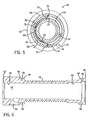
- the torch head body 62 has a plurality of cylindrical surfaces 94 for receiving the sleeve 66.
- a pair of notches 96 is provided in the torch head body 62 to receive the silver rings 88.
- the sleeve 66 may be secured to the torch head body 62 by brazing, soldering, or some other method.
- the torch head body 62 is comprised of a copper-lead-nickel alloy.
- other conductive materials may be used to form the torch head body 62.
- the sleeve 66 is generally cylindrical to define a flow volume around the torch head body 62.
- the sleeve 66 has two holes: the liquid inlet 70 and the liquid outlet 72.
- the sleeve 66 is formed with two grooves 76 located 180 degrees apart to engage the flanges 74 of the baffle 68 illustrated in Figure 5.
- the sleeve 66 may be configured in a different orientation if the flanges 44 of the baffle 68 are oriented in a different orientation.
- the sleeve 66 is adapted to couple electricity from the liquid supply tube 54 to the torch head body 62.
- the sleeve 66 is comprised of copper, an excellent conductor.
- other conductive materials may be used to form the sleeve 66.
- the illustrated baffle 68 has a generally semi-cylindrical shape contoured to extend around the torch head body 62.
- the baffle 68 may be adapted with a different shape or contour.
- the baffle 68 is formed of a flexible material to enable the flanges 74 of the baffle 68 to be flexed into grooves 76 in sleeve 66.
- the baffle 68 is comprised of stainless steel.
- other materials may be used to form the baffle 68.
- Cooling liquid 24 is directed to flow over a helical cooling fin 64 extending along a length of a torch head body 62 to remove heat from the torch head body 62.
- the helical cooling fin 64 increases the effectiveness of convective heat transfer from the torch head body 62 to the cooling liquid 24.
- the helical cooling fin 64 increases the surface area of the torch head body 62 available for heat transfer.
- the helical cooling fin 64 induces the cooling liquid 24 to flow helically around the torch head body 62, increasing the length of travel of the cooling liquid 24 over the torch head body 62.
- the baffle 68 directs cooling liquid 24 to flow along the length of the torch head body 62 with the liquid inlet 70 and the liquid outlet 72 being located adjacent to each other at one end of the torch head 46.
Landscapes
- Engineering & Computer Science (AREA)
- Physics & Mathematics (AREA)
- Plasma & Fusion (AREA)
- Mechanical Engineering (AREA)
- Arc Welding In General (AREA)
Abstract
Description
Claims (10)
- A liquid-cooled welding device (14), comprising:a torch head body (62) operable to conduct electricity to a welding electrode (44) disposed therein, the torch head body (62) having a helical cooling fin (64) extending along a length of the torch head body (62);a sleeve (66) disposed around the torch head body (62), wherein the sleeve (66) has a liquid inlet (70) and a liquid outlet (72) to enable a liquid (24) to flow over the torch head body (62), the liquid outlet (72) being disposed adjacent to the liquid inlet (70); anda baffle (68) disposed within the sleeve (66) between the liquid inlet (70) and the liquid outlet (72) to direct the liquid (24) to flow along the length of the torch head body (62) to enable the helical cooling fin (64) to transfer heat to the liquid (24).
- The welding device (14) as recited in claim 1, comprising a liquid supply line (54) coupled to the liquid inlet (70) and a liquid return line (56) coupled to the liquid outlet (72).
- The welding device (14) as recited in claim 2, wherein the helical cooling fin (64) induces the liquid (24) to flow helically around the torch head body (62) from the liquid inlet (70) to an end of the baffle (68).
- The welding device (14) as recited in claim 2, wherein the liquid (24) flows helically around the torch head body (62) from an end (80) of the baffle (68) to the liquid outlet (72).
- The welding device (14) as recited in claim 2, comprising a gas supply line (52) coupled to a passageway (84) in the torch head body (62).
- The welding device (14) as recited in claim 5, comprising a handle (51) removably secured to the torch head body (62) over the liquid supply line (54), the liquid return line (56), and the gas line (54).
- The welding device (14) as recited in claim 1, wherein liquid (24) flows from the liquid inlet (70) to the end (80) of the baffle (68) in an annular fluid channel defined by an inner surface (78) of the baffle (68) and an outer surface of the torch head body (62).
- The welding device (14) as recited in claim 1, wherein the torch head body (62) comprises:an axial channel (86) extending through the torch head body (62) to enable the torch head body (62) to receive a welding electrode (44); anda gas inlet (84) extending through a side of the torch head body (62) into the hollow interior (86) to enable gas (20) to enter the axial channel (86) and flow through the axial channel (86) around the welding electrode (44).
- The welding device (14) as recited in claim 8, wherein the gas inlet (84)is disposed adjacent to the liquid inlet (70) and the liquid outlet (72).
- The welding device (14) as recited in claim 9, wherein gas (20) flows through the axial channel (86) in the same axial direction as the cooling liquid (24) flows from the liquid inlet (70) to the end (80) of the baffle (68).
Applications Claiming Priority (2)
| Application Number | Priority Date | Filing Date | Title |
|---|---|---|---|
| US677781 | 1984-12-04 | ||
| US10/677,781 US6930281B2 (en) | 2003-10-02 | 2003-10-02 | System for cooling a welding device |
Publications (2)
| Publication Number | Publication Date |
|---|---|
| EP1520650A1 true EP1520650A1 (en) | 2005-04-06 |
| EP1520650B1 EP1520650B1 (en) | 2009-06-17 |
Family
ID=34314060
Family Applications (1)
| Application Number | Title | Priority Date | Filing Date |
|---|---|---|---|
| EP04019894A Expired - Lifetime EP1520650B1 (en) | 2003-10-02 | 2004-08-23 | System for cooling a liquid-cooled welding device |
Country Status (5)
| Country | Link |
|---|---|
| US (1) | US6930281B2 (en) |
| EP (1) | EP1520650B1 (en) |
| JP (1) | JP4938228B2 (en) |
| CA (1) | CA2479864C (en) |
| DE (1) | DE602004021543D1 (en) |
Cited By (1)
| Publication number | Priority date | Publication date | Assignee | Title |
|---|---|---|---|---|
| WO2019175345A1 (en) * | 2018-03-14 | 2019-09-19 | Quaeckber Joerg | Welding torch |
Families Citing this family (24)
| Publication number | Priority date | Publication date | Assignee | Title |
|---|---|---|---|---|
| US20060226132A1 (en) * | 2005-04-08 | 2006-10-12 | Giese William R | Welding torch with enhanced cooling |
| US8258423B2 (en) * | 2009-08-10 | 2012-09-04 | The Esab Group, Inc. | Retract start plasma torch with reversible coolant flow |
| US8669489B2 (en) * | 2010-12-16 | 2014-03-11 | Illinois Tool Works Inc. | High flow power cable for small welding torch |
| US9006610B2 (en) * | 2010-12-16 | 2015-04-14 | Illinois Tool Works Inc. | Tungsten inert gas welding torch with improved liquid cooling |
| US10391579B2 (en) * | 2013-03-15 | 2019-08-27 | Huys Industries Limited | Ventilated vibrating electrode holder |
| US10391574B2 (en) | 2013-12-16 | 2019-08-27 | Huys Industries Limited | Welding method and apparatus therefor |
| US10675699B2 (en) | 2015-12-10 | 2020-06-09 | Illinois Tool Works Inc. | Systems, methods, and apparatus to preheat welding wire |
| US12194579B2 (en) | 2015-12-10 | 2025-01-14 | Illinois Tool Works Inc. | Systems, methods, and apparatus to preheat welding wire |
| US10350691B2 (en) | 2017-01-13 | 2019-07-16 | Fca Us Llc | Water cooled wire feed tip collar for laser brazing system |
| CN111315524A (en) | 2017-06-09 | 2020-06-19 | 伊利诺斯工具制品有限公司 | Welding torch with two contacts and multiple liquid-cooled components for conducting current to the contacts |
| US11590598B2 (en) | 2017-06-09 | 2023-02-28 | Illinois Tool Works Inc. | Systems, methods, and apparatus to preheat welding wire |
| EP3634684B1 (en) | 2017-06-09 | 2022-10-05 | Illinois Tool Works Inc. | Welding torch with a first contact tip to preheat welding wire and a second contact tip |
| CN111386168A (en) | 2017-06-09 | 2020-07-07 | 伊利诺斯工具制品有限公司 | Welding assembly for a welding torch with two contact tips and a cooling body for cooling and conducting electric current |
| US11524354B2 (en) | 2017-06-09 | 2022-12-13 | Illinois Tool Works Inc. | Systems, methods, and apparatus to control weld current in a preheating system |
| US11020813B2 (en) | 2017-09-13 | 2021-06-01 | Illinois Tool Works Inc. | Systems, methods, and apparatus to reduce cast in a welding wire |
| US11014185B2 (en) | 2018-09-27 | 2021-05-25 | Illinois Tool Works Inc. | Systems, methods, and apparatus for control of wire preheating in welding-type systems |
| EP3898055A2 (en) | 2018-12-19 | 2021-10-27 | Illinois Tool Works, Inc. | Contact tip, wire preheating assembly, contact tip assembly and consumable electrode-fed welding type system |
| US12409504B2 (en) | 2019-02-05 | 2025-09-09 | Huys Industries Limited | Welding applicator and method of application |
| US12583048B2 (en) | 2019-03-29 | 2026-03-24 | Illinois Tool Works Inc. | Methods and apparatus to convert welding-type power to welding-type power and resistive preheating power |
| US12103121B2 (en) | 2019-04-30 | 2024-10-01 | Illinois Tool Works Inc. | Methods and apparatus to control welding power and preheating power |
| US11772182B2 (en) | 2019-12-20 | 2023-10-03 | Illinois Tool Works Inc. | Systems and methods for gas control during welding wire pretreatments |
| CA3181027A1 (en) | 2020-04-14 | 2021-10-21 | Stephen PETERKIN | Welded assembly and method of welding using electro-spark discharge |
| CN118284487A (en) * | 2021-10-21 | 2024-07-02 | 博沃艾特加拿大有限公司 | Welding device and method for manufacturing the same |
| US20250332666A1 (en) * | 2024-04-29 | 2025-10-30 | Illinois Tool Works Inc. | Coolant flow connections for cooling systems |
Citations (1)
| Publication number | Priority date | Publication date | Assignee | Title |
|---|---|---|---|---|
| US5473132A (en) * | 1993-04-13 | 1995-12-05 | Alexander Binzel Gmbh & Co. Kg | Arcwelding or cutting torch |
Family Cites Families (27)
| Publication number | Priority date | Publication date | Assignee | Title |
|---|---|---|---|---|
| US3250889A (en) * | 1964-05-21 | 1966-05-10 | Louis F Himmelman | Electric welding torch |
| US3283121A (en) | 1965-07-21 | 1966-11-01 | Bernard Welding Equip Co | Arc welding gun |
| US3676640A (en) | 1969-06-05 | 1972-07-11 | Dover Corp | Arc welding gun |
| US3634643A (en) | 1970-12-09 | 1972-01-11 | Himmelmann Louis F | Gas-shielded water-cooled electric welding torch |
| US3728514A (en) | 1970-12-21 | 1973-04-17 | Bernard Welding Equipment Co | Thermionic insulated arc welding gun |
| US3746832A (en) | 1971-07-29 | 1973-07-17 | Dover Corp | Arc welding gun unitized gas hose and electrical control cord |
| US3803381A (en) | 1971-12-22 | 1974-04-09 | Dover Corp | Arc welding gun |
| US4105891A (en) | 1975-01-13 | 1978-08-08 | Union Carbide Corporation | Metal-inert-gas welding torch |
| US3976852A (en) | 1975-08-20 | 1976-08-24 | Chemetron Corporation | Welding torch |
| CH625148A5 (en) | 1978-07-25 | 1981-09-15 | Roberto Torrani | |
| US4313046A (en) | 1980-03-10 | 1982-01-26 | Hobart Brothers Company | Water cooled welding gun |
| US4508951A (en) | 1982-08-19 | 1985-04-02 | Richard B. Rehrig | Fluid baffle assembly for a water-cooled welding torch |
| US4554432A (en) | 1984-10-05 | 1985-11-19 | Dover Corporation | Components for gas metal arc welding gun |
| JPS6489872A (en) * | 1987-09-30 | 1989-04-05 | Sony Corp | Teletext receiver |
| US5045665A (en) | 1990-04-16 | 1991-09-03 | Delaware Capital Formation | Fluid cooled torch |
| IT225262Z2 (en) | 1991-09-25 | 1996-10-24 | "TORCH FOR ELECTRIC CONTINUOUS WIRE WELDERS, WITH NATURAL, GAS OR WATER COOLING, CHARACTERIZED BY A RAPID AND SEM PLIFIED ASSEMBLY". | |
| US5220144A (en) | 1992-03-23 | 1993-06-15 | Hobart Brothers Company | Water cooled orbital welding head |
| JPH0671450A (en) * | 1992-08-27 | 1994-03-15 | Brother Ind Ltd | Electrode for plasma arc machine |
| US5384447A (en) | 1993-01-06 | 1995-01-24 | Bernard Welding Equipment Company | Electric arc welding gun |
| US5288963A (en) | 1993-07-22 | 1994-02-22 | Hobart Brothers Company | Actively cooled weld head cassette |
| US5403987A (en) | 1994-03-17 | 1995-04-04 | Rehrig; Richard B. | Gas shielded welding torch |
| US5571427A (en) | 1995-04-03 | 1996-11-05 | Weldcraft Products, Inc. | Torch head and cable assembly for a welding device |
| US5611951A (en) | 1995-12-20 | 1997-03-18 | Kunz; Erwin | Arc welding torch |
| US6078023A (en) | 1998-04-27 | 2000-06-20 | Jones; Glen A. | Liquid-cooled welding torch assembly |
| US6005221A (en) * | 1998-08-03 | 1999-12-21 | Cusick, Iii; Joseph B. | Pressurized air cooled tungsten inert gas welding apparatus |
| US6399913B1 (en) | 2000-11-01 | 2002-06-04 | Illinois Tool Works Inc. | Ergonomic TIG torch |
| JP2003039172A (en) * | 2001-07-25 | 2003-02-12 | Kobe Steel Ltd | Water cooling gas shield arc two electrode integrated welding torch |
-
2003
- 2003-10-02 US US10/677,781 patent/US6930281B2/en not_active Expired - Lifetime
-
2004
- 2004-08-23 EP EP04019894A patent/EP1520650B1/en not_active Expired - Lifetime
- 2004-08-23 DE DE602004021543T patent/DE602004021543D1/en not_active Expired - Lifetime
- 2004-08-31 CA CA2479864A patent/CA2479864C/en not_active Expired - Fee Related
- 2004-09-03 JP JP2004257322A patent/JP4938228B2/en not_active Expired - Fee Related
Patent Citations (1)
| Publication number | Priority date | Publication date | Assignee | Title |
|---|---|---|---|---|
| US5473132A (en) * | 1993-04-13 | 1995-12-05 | Alexander Binzel Gmbh & Co. Kg | Arcwelding or cutting torch |
Cited By (1)
| Publication number | Priority date | Publication date | Assignee | Title |
|---|---|---|---|---|
| WO2019175345A1 (en) * | 2018-03-14 | 2019-09-19 | Quaeckber Joerg | Welding torch |
Also Published As
| Publication number | Publication date |
|---|---|
| JP4938228B2 (en) | 2012-05-23 |
| CA2479864C (en) | 2010-06-01 |
| JP2005111560A (en) | 2005-04-28 |
| DE602004021543D1 (en) | 2009-07-30 |
| US20050072762A1 (en) | 2005-04-07 |
| CA2479864A1 (en) | 2005-04-02 |
| EP1520650B1 (en) | 2009-06-17 |
| US6930281B2 (en) | 2005-08-16 |
Similar Documents
| Publication | Publication Date | Title |
|---|---|---|
| EP1520650B1 (en) | System for cooling a liquid-cooled welding device | |
| US8772673B2 (en) | Welding gun | |
| EP1287937B1 (en) | A welding torch for use in gas metal arc welding | |
| EP2308630B1 (en) | Narrow groove gas metal arc welding torch | |
| US4354088A (en) | Gas shielded welding torch | |
| US4435636A (en) | Desoldering tool | |
| US7105766B2 (en) | Welding torch having removable handle and method of operating same | |
| JP5527763B2 (en) | Welding torch | |
| US7453050B2 (en) | Flexible welding implement and method of manufacturing same | |
| US7253373B2 (en) | Air-cooled arc welding implement | |
| US20090277892A1 (en) | cooling of a welding implement | |
| WO2016203213A2 (en) | Welding torch | |
| CA1045687A (en) | Welding torch | |
| WO1990010366A1 (en) | Plasma arc torch | |
| US3158730A (en) | Gas shielded arc torch | |
| JP7780325B2 (en) | Welding electrodes and welding torches | |
| US20230125948A1 (en) | Welding device and method of manufacture | |
| JPH11197849A (en) | Cooling structure of welding electrode | |
| JPH0994663A (en) | Welding torch | |
| TWM325183U (en) | Air/water cooling dual-functional argon welding machine | |
| JP2010005695A (en) | Conduit cable | |
| KR20170106840A (en) | means of cooling welding torch and combined welding torch having it | |
| JP2000061652A (en) | One side spot welding equipment and its method | |
| SE192499C1 (en) | ||
| HK1021889A (en) | Wire feeder torch |
Legal Events
| Date | Code | Title | Description |
|---|---|---|---|
| PUAI | Public reference made under article 153(3) epc to a published international application that has entered the european phase |
Free format text: ORIGINAL CODE: 0009012 |
|
| 17P | Request for examination filed |
Effective date: 20040823 |
|
| AK | Designated contracting states |
Kind code of ref document: A1 Designated state(s): AT BE BG CH CY CZ DE DK EE ES FI FR GB GR HU IE IT LI LU MC NL PL PT RO SE SI SK TR |
|
| AX | Request for extension of the european patent |
Extension state: AL HR LT LV MK |
|
| AKX | Designation fees paid |
Designated state(s): DE FR GB IT |
|
| 17Q | First examination report despatched |
Effective date: 20071113 |
|
| GRAP | Despatch of communication of intention to grant a patent |
Free format text: ORIGINAL CODE: EPIDOSNIGR1 |
|
| GRAS | Grant fee paid |
Free format text: ORIGINAL CODE: EPIDOSNIGR3 |
|
| GRAA | (expected) grant |
Free format text: ORIGINAL CODE: 0009210 |
|
| AK | Designated contracting states |
Kind code of ref document: B1 Designated state(s): DE FR GB IT |
|
| REG | Reference to a national code |
Ref country code: GB Ref legal event code: FG4D |
|
| REF | Corresponds to: |
Ref document number: 602004021543 Country of ref document: DE Date of ref document: 20090730 Kind code of ref document: P |
|
| PLBE | No opposition filed within time limit |
Free format text: ORIGINAL CODE: 0009261 |
|
| STAA | Information on the status of an ep patent application or granted ep patent |
Free format text: STATUS: NO OPPOSITION FILED WITHIN TIME LIMIT |
|
| 26N | No opposition filed |
Effective date: 20100318 |
|
| PGFP | Annual fee paid to national office [announced via postgrant information from national office to epo] |
Ref country code: GB Payment date: 20140827 Year of fee payment: 11 |
|
| PGFP | Annual fee paid to national office [announced via postgrant information from national office to epo] |
Ref country code: IT Payment date: 20140825 Year of fee payment: 11 |
|
| REG | Reference to a national code |
Ref country code: FR Ref legal event code: PLFP Year of fee payment: 12 |
|
| PGFP | Annual fee paid to national office [announced via postgrant information from national office to epo] |
Ref country code: FR Payment date: 20150817 Year of fee payment: 12 |
|
| GBPC | Gb: european patent ceased through non-payment of renewal fee |
Effective date: 20150823 |
|
| PG25 | Lapsed in a contracting state [announced via postgrant information from national office to epo] |
Ref country code: IT Free format text: LAPSE BECAUSE OF NON-PAYMENT OF DUE FEES Effective date: 20150823 |
|
| PG25 | Lapsed in a contracting state [announced via postgrant information from national office to epo] |
Ref country code: GB Free format text: LAPSE BECAUSE OF NON-PAYMENT OF DUE FEES Effective date: 20150823 |
|
| REG | Reference to a national code |
Ref country code: FR Ref legal event code: ST Effective date: 20170428 |
|
| PG25 | Lapsed in a contracting state [announced via postgrant information from national office to epo] |
Ref country code: FR Free format text: LAPSE BECAUSE OF NON-PAYMENT OF DUE FEES Effective date: 20160831 |
|
| PGFP | Annual fee paid to national office [announced via postgrant information from national office to epo] |
Ref country code: DE Payment date: 20200827 Year of fee payment: 17 |
|
| REG | Reference to a national code |
Ref country code: DE Ref legal event code: R119 Ref document number: 602004021543 Country of ref document: DE |
|
| PG25 | Lapsed in a contracting state [announced via postgrant information from national office to epo] |
Ref country code: DE Free format text: LAPSE BECAUSE OF NON-PAYMENT OF DUE FEES Effective date: 20220301 |