EP1520649A2 - Cutting unit for an impact cutting device and die element therefor - Google Patents
Cutting unit for an impact cutting device and die element therefor Download PDFInfo
- Publication number
- EP1520649A2 EP1520649A2 EP04019642A EP04019642A EP1520649A2 EP 1520649 A2 EP1520649 A2 EP 1520649A2 EP 04019642 A EP04019642 A EP 04019642A EP 04019642 A EP04019642 A EP 04019642A EP 1520649 A2 EP1520649 A2 EP 1520649A2
- Authority
- EP
- European Patent Office
- Prior art keywords
- die
- workpiece
- impact
- cutting unit
- cutting
- Prior art date
- Legal status (The legal status is an assumption and is not a legal conclusion. Google has not performed a legal analysis and makes no representation as to the accuracy of the status listed.)
- Granted
Links
Images


Classifications
-
- B—PERFORMING OPERATIONS; TRANSPORTING
- B23—MACHINE TOOLS; METAL-WORKING NOT OTHERWISE PROVIDED FOR
- B23D—PLANING; SLOTTING; SHEARING; BROACHING; SAWING; FILING; SCRAPING; LIKE OPERATIONS FOR WORKING METAL BY REMOVING MATERIAL, NOT OTHERWISE PROVIDED FOR
- B23D15/00—Shearing machines or shearing devices cutting by blades which move parallel to themselves
- B23D15/12—Shearing machines or shearing devices cutting by blades which move parallel to themselves characterised by drives or gearings therefor
-
- B—PERFORMING OPERATIONS; TRANSPORTING
- B23—MACHINE TOOLS; METAL-WORKING NOT OTHERWISE PROVIDED FOR
- B23D—PLANING; SLOTTING; SHEARING; BROACHING; SAWING; FILING; SCRAPING; LIKE OPERATIONS FOR WORKING METAL BY REMOVING MATERIAL, NOT OTHERWISE PROVIDED FOR
- B23D35/00—Tools for shearing machines or shearing devices; Holders or chucks for shearing tools
- B23D35/002—Means for mounting the cutting members
-
- Y—GENERAL TAGGING OF NEW TECHNOLOGICAL DEVELOPMENTS; GENERAL TAGGING OF CROSS-SECTIONAL TECHNOLOGIES SPANNING OVER SEVERAL SECTIONS OF THE IPC; TECHNICAL SUBJECTS COVERED BY FORMER USPC CROSS-REFERENCE ART COLLECTIONS [XRACs] AND DIGESTS
- Y10—TECHNICAL SUBJECTS COVERED BY FORMER USPC
- Y10T—TECHNICAL SUBJECTS COVERED BY FORMER US CLASSIFICATION
- Y10T83/00—Cutting
- Y10T83/384—By tool inside hollow work
- Y10T83/394—One tool having unidirectional rotary motion
-
- Y—GENERAL TAGGING OF NEW TECHNOLOGICAL DEVELOPMENTS; GENERAL TAGGING OF CROSS-SECTIONAL TECHNOLOGIES SPANNING OVER SEVERAL SECTIONS OF THE IPC; TECHNICAL SUBJECTS COVERED BY FORMER USPC CROSS-REFERENCE ART COLLECTIONS [XRACs] AND DIGESTS
- Y10—TECHNICAL SUBJECTS COVERED BY FORMER USPC
- Y10T—TECHNICAL SUBJECTS COVERED BY FORMER US CLASSIFICATION
- Y10T83/00—Cutting
- Y10T83/404—By means to misalign aligned apertured tools
- Y10T83/416—Rotary relative movement solely about a single pivot
-
- Y—GENERAL TAGGING OF NEW TECHNOLOGICAL DEVELOPMENTS; GENERAL TAGGING OF CROSS-SECTIONAL TECHNOLOGIES SPANNING OVER SEVERAL SECTIONS OF THE IPC; TECHNICAL SUBJECTS COVERED BY FORMER USPC CROSS-REFERENCE ART COLLECTIONS [XRACs] AND DIGESTS
- Y10—TECHNICAL SUBJECTS COVERED BY FORMER USPC
- Y10T—TECHNICAL SUBJECTS COVERED BY FORMER US CLASSIFICATION
- Y10T83/00—Cutting
- Y10T83/687—By tool reciprocable along elongated edge
- Y10T83/688—With dynamic balancing or shock absorbing means
-
- Y—GENERAL TAGGING OF NEW TECHNOLOGICAL DEVELOPMENTS; GENERAL TAGGING OF CROSS-SECTIONAL TECHNOLOGIES SPANNING OVER SEVERAL SECTIONS OF THE IPC; TECHNICAL SUBJECTS COVERED BY FORMER USPC CROSS-REFERENCE ART COLLECTIONS [XRACs] AND DIGESTS
- Y10—TECHNICAL SUBJECTS COVERED BY FORMER USPC
- Y10T—TECHNICAL SUBJECTS COVERED BY FORMER US CLASSIFICATION
- Y10T83/00—Cutting
- Y10T83/748—With work immobilizer
- Y10T83/7487—Means to clamp work
-
- Y—GENERAL TAGGING OF NEW TECHNOLOGICAL DEVELOPMENTS; GENERAL TAGGING OF CROSS-SECTIONAL TECHNOLOGIES SPANNING OVER SEVERAL SECTIONS OF THE IPC; TECHNICAL SUBJECTS COVERED BY FORMER USPC CROSS-REFERENCE ART COLLECTIONS [XRACs] AND DIGESTS
- Y10—TECHNICAL SUBJECTS COVERED BY FORMER USPC
- Y10T—TECHNICAL SUBJECTS COVERED BY FORMER US CLASSIFICATION
- Y10T83/00—Cutting
- Y10T83/869—Means to drive or to guide tool
- Y10T83/8821—With simple rectilinear reciprocating motion only
Definitions
- the invention relates to a cutting unit, in particular for a striking cutting device for adiabatic cutting of workpieces, and a die element for such a cutting unit.
- a high impulse becomes a movable impulse Transfer matrix, which is laterally displaced by the pulse against a rigid die becomes.
- the workpiece is in one pass through the matrices clamped, wherein the cross section corresponds to that of the workpiece to be separated.
- the observations show that the workpiece to be cut is very short, but violently acting impulse is separable with almost no plastic deformation.
- the displaceable die is compared only by a few tenths of a millimeter offset the rigid die.
- the problem here is on the one hand, a reproducible To transmit pulse with exact power to the movable die, and on the other hand the pulse energy, which was not converted into separation energy, so to dampen that the impact cutting device is also suitable for continuous use.
- US 4,840,236 proposes a hydraulic-pneumatic actuator for transmission high pulses on a workpiece to be compressed or cut.
- a cylinder design for a high acceleration of the piston will also proposed an arrangement for deceleration of the piston.
- the cross-sectional area of the die elements is conventional on the outer contours adjusted to the workpiece to be separated, with tolerance due to a game between the Matrizenelement inner wall and the workpiece outer wall be present got to. Due to this game it comes in particular for longer workpieces to a Angular offset of the stored within the die element workpiece during the flapping phase and movement of the movable die element, so that the cut surface against the original orientation of the workpiece in the die elements can be slightly inclined.
- the movable die element, the resting mounted die element or both die elements one have variable cross-section for receiving the workpiece.
- the cross section can be made smaller in the direction of impact, so that by reducing the cross section in the direction of impact before impact (preferably the resting mounted die element) or during the beating phase (preferably the movable die element) the cross section on the actual cross section of Workpiece is adjusted. This prevents an angular offset of the surface to the original one Alignment of the workpiece to be machined.
- the changeable allows Cross section at least in the direction of impact an actual system of the die element on the outside of the workpiece.
- a clamping or clamping device is provided with which the variable Cross section before and during the execution of the separation stroke is reducible, so that the workpiece to be separated is received without play in the die element. Clamping or clamping may occur with the movable and / or fixed die element respectively.
- a restoring device is provided, with the clamping of the workpiece effected by means of the clamping or tensioning device is detachable after separation.
- one or both die elements are constructed at least in two parts, so that a relative movement of the individual parts of a die element an attachment the same on the outer surface of the workpiece allows.
- the die element separated at least transversely to the direction of impact wherein advantageous opposite a one-piece die element whose cross-sectional area is the tolerance of the workpiece, the height of the parting line is dimensioned so that this approximately the difference between the largest cross-section of the workpiece and the smallest Cross section of the workpiece is.
- a matrix element with a variable cross-section against each other adjustable inner segments wherein between each two inner segments an elastic Element is arranged, in particular under bias between the inner segments are clamped.
- the inner segments are separated from each other and released a workpiece as soon as the clamping of the inner segments released is. It is advantageous at least one of the inner segments by means of a rotation secured against rotation.
- At least one die element has one of Receiving opening for the workpiece to be separated outgoing gap with changeable Gap on.
- an actuating device for changing the Gap provided.
- the gap is advantageous by the actuator and / or the insertion of the workpiece to be machined is expandable.
- a damping device between the side opposite the flip side of the movable die and arranged the support structure.
- This arrangement can also be applied to a die element provided without changeable opening cross-section for receiving the workpiece be (see claim 17).
- the damping element is excess energy from Shock damped if the impact energy is not completely in separation energy and heat energy could be transferred.
- the spread of excess impact energy which vary greatly with workpieces subject to tolerances from beat to beat can be limited to the smallest possible portion of the cutting tool and largely prevents propagation to a cutting device.
- the damping element is biased in the direction of impact with a bias, preferably on the strength of the workpiece to be machined depends. Due to the bias, the movable die element shifts with fitting of the impact element on the top of the movable die not immediately, but the movable die is first between the striking element and the pad (damping element) clamped with a force up to Height of preload. Only when the preload is overcome, the movable sits Die element in motion and the further impact energy is then through the adiabatic separation and optionally further damping by the damping element implemented. By clamping the movable die element between Impact device and damping element becomes a stabilizing orientation of the movable die element within the cutting unit.
- the clamping first a play-free system of Matrizeninnen vom (in Impact direction) on the outer surface of the workpiece, allowing tilting of the workpiece prevents the onset of the movement phase of the movable die element becomes.
- the biasing device Is an adjustability of the bias voltage on the damping element by means of a biasing device provided, so can the clamping force in dependence of the strength or the shape of the workpiece to be machined.
- the bias on the damping element automatically adjustable, so that during the ongoing production operation an adjustment or optimization the bias is enabled.
- the biasing device can be the Increase and / or reduce the pretensioning of the damping element.
- the damping device comprises an air gap, in particular compressed air with predetermined pressure and / or flow can be introduced.
- the Impact element which transmits the pulse to a cutting unit, releasably connected to a Acceleration unit is coupled.
- a coupling device decoupling between Acceleration unit and impact element Before hitting the impact element on the Cutting unit is done by a coupling device decoupling between Acceleration unit and impact element.
- the acceleration can be canceled just then when the striking element required for the workpiece to be machined pulse so that e.g. the braking of the acceleration unit again not reacts to the striking element and its impulse.
- the free 'route' of the Impact element in front of the cutting unit is also an exact adjustment between the acceleration unit and cutting unit for reproducing a given one Impact impulses not necessary.
- Very particularly advantageous engages a driver of the acceleration unit in the Impact element and performs this at least during the acceleration phase or over the acceleration section with.
- the acceleration force transferred to the striking element and on the other hand a secure leadership achieved the impact element.
- the coupling 'at least' over an acceleration section here means that either the driver only during the acceleration phase or coupled to the impact element via the acceleration section is and immediately takes place after the acceleration decoupling. Or It is still a predetermined time or distance after acceleration a coupling maintained so that the driver coupled force-free to the impact element.
- the previous impact cutters are optimized to a workpiece (usually a specific Starting material and with a given material thickness in wire form) with very high stroke rate, allowing many wire pens for further processing can be generated.
- a workpiece usually a specific Starting material and with a given material thickness in wire form
- the system goes through Experiments optimized so that on the one hand a clean material separation occurs and on the other hand the lowest possible conversion of the impact pulse into shock waves within of the device occurs.
- the optimized parameters justify the optimization time.
- Type of workpiece material shape, material thickness, material used, etc.
- Deviations in the material quality form errors, tolerances, position of the material in the cutting device, voids, etc.
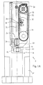
- Fig. 1A shows schematically a front view of the construction of a percussion cutting machine 1.
- the workpiece 2 to be cut (FIG. 1C) is clamped in a die block 10 and is there by applying blows by means of the hammer unit 20 cut.
- An impact hammer 21 of the hammer unit 20 is driven by an accelerator 30 accelerates.
- the die block 10 rests on a support structure 31 at The also a guide 22 of the hammer unit 20 and the acceleration unit 30th are coupled.
- Parts of the support structure 31 are formed of mineral casting, in addition to the high wearing property a particularly good damping against the spread of Has vibrations and shock waves.
- a propagation of vibrations or Shock waves starting from the matrix block on the workshop floor or on the Acceleration unit 30 and the hammer unit 20 is thus avoided.
- Vice versa is also the propagation of vibrations starting from the hammer unit 20 strongly steamed.
- a chain 32 When accelerating unit 30, a chain 32 extends over an upper drive wheel 33 and a lower deflecting wheel 34.
- the upper driving wheel 33 is controlled by an NC Servomotor 82 (Fig. 1D) driven, the short-term, very high accelerations allows.
- the chain 32 carries a carriage 36a, of which a driver 36 protrudes, which in turn engages in a recess 28 of the hammer 21.
- At least over part of the acceleration section runs next to the chain 32 a Chain guide 35.
- the chain guide comprises an actuator, here a pneumatic Actuator, which is a chain running along the chain guide rail perpendicular to Chain delivered.
- the acceleration phase is the chain guide rail of the chain provided (as shown in Fig. 1A) and limits or attenuates lateral, perpendicular to Pull direction occurring chain rashes by the acceleration or the later Braking could be caused.
- the contact surface of the chain guide rail to the chain is provided with a sliding material.
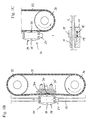
- Fig. 1B shows a partial view of the impact cutting machine in one phase just before the coupling of the driver 36 in the recess 28 of the hammer.
- the hammer is shown by a lifting unit 37 after the impact in the in Fig. 1B Position raised and the carriage 36a is driven by the chain 33 upwards.
- Fig. 1C shows a phase during acceleration during which the driver 36 completely engages in the recess 28 of the hammer 21.
- the chain 32 is alternatively or additionally driven by the lower wheel 34, so that the chain between the lower and upper wheel 34, 35 stretched over the acceleration section and stiffened.
- FIG. 2 shows a schematic cross-sectional view of the hammer unit 20 from above.
- the hammer 21 is guided in a first and second guide rail 23, 24 of the guide 22.
- the hammer 21 is not directly in contact with the guide rails 23, 24, but is via slide blocks 26, which rest in wells 25, on the rails 22, 23 slidably guided.
- the sliding blocks 26 are, for example, metal matrices, in The molybdenum sulfide (MoS) is incorporated as a lubricant.
- MoS molybdenum sulfide
- the driver 36 of the acceleration unit 30th has lateral projections which are connected via a web to the carriage 36a are.
- the two lateral projections of the driver 36 engage in the two lateral Recesses 28 on the hammer 21 a.
- To the side walls of the recesses 28 connect ramps 29, wherein the projections of the driver 36 when returning of the hammer 21 from the lower position (at die block 10) over the ramp 29 slide.
- the chain 32 and the carriage 36a are deflected (FIG. 1B) and after reaching the recess 28, the projections of the driver 36 jump into the Recess 28, so that the hammer 21 is raised by the acceleration unit 30 and can be returned to its starting position.
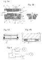
- FIG. 3A shows a tool holder 11 of the die block 10 in cross section.
- a rigid Die 12 and a movable die 13 used interchangeably.
- the matrix pair 12, 13 has a first and second passage 14, 15, whose cross-section each on the adapted to be machined workpiece.
- the die pair 12, 13 exchanged in the tool holder 11.
- the rigid die 12 fixed in the tool holder 11th held while below the movable die 13, a recess 18 is arranged is that allows a slight movement of the die 13 down during the strike.
- the hammer 21 and / or the dies 12, 13 are made of a particularly impact-resistant Steel formed, for example, the product of the identification number of the company STM steel 1.2379 (special steel).
- STM steel 1.2379 special steel
- the second passage 15 of the movable die 13 widens from the interface to the entrance and exit side 17 out.
- the workpiece is in Area of the cutting edge set free of play, while for longer workpieces offset the end of the workpiece outside of the die 13 during impact cutting avoided becomes. This reduces the mass to be accelerated during the impact and the applied pulse energy is largely independent for longer workpieces on the length of the workpiece to be cut off.
- a damping element 19 is arranged, which the impact pulse or the part of the impact pulse that is not in separation and deformation energy was converted to shock, fields and converts to heat.
- the damping element 19 sets a displacement of the movable die 13 a very high power so that even in the presence of excess energy within a very short deflection distance is completely decelerated.
- Figs. 4A and 4B show two embodiments of the damping element 19.
- the first spring ring 51 is formed of five interlocked, closed ring elements.
- Friction spring sets the displacement of the rings by friction in heat energy and causes efficient damping of the movable die 13.
- With 52 is denotes a second spring ring assembly, wherein the rings partially over each other and are positioned with each other, so that the base of the recess 18 on is exploited.
- the tool holder 11 is associated with a sensor 58, which controls the vibrations registered the tool holder 11 and / or measures the air pressure in the recess 18. This can be during the execution of the blow the presence and the Measure the height of vibrations.
- the height of the vibrations is a measure of the excess Impact energy that was not converted to separate the workpiece. Since the surplus energy must be avoided as far as possible, the signal is used the sensor 58 for optimizing the parameters of the impact cutting machine and the Control of the function of impact cutting. As shown in Fig.
- one of Well 18 associated pressure sensor used, so can the perfect Resetting the movable die 13 when introducing compressed air into the recess 18 are checked, wherein after provision of the die 13 in the starting position the pressure within the recess 18 drop to a predetermined value got to.
- Fig. 3B shows an embodiment of a compressed air passage 55 and / or 56, wherein a plurality such holes are provided distributed in the tool holder 11 over the surface, so that a uniform air cushion is formed.
- a hole diameter of A few micrometers (10 - 200 microns) can be used when compressing the air in the columns or in the recess 18, the compressed air is not fast enough through the holes 55, 56 escape and deflection causes a high air pressure in the Columns and / or the recess 18 a.
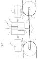
- Fig. 5 shows schematically the arrangement of a double-dash cutting machine 60.
- a cutting unit 61 is floating or at least in the direction of impact deflectable in both directions in a tool holder, not shown here stored.
- a first and second dies 62, 63 are against each other and with respect. of the tool holder displaceable. As shown in Fig. 5, the workpiece of inserted above and removed the deflected parts down.
- the orientation is here only as an example.
- the matrices 62, 63 are via a first and second damping element 64, 65 stored against each other.
- a first and a second hammer 69, 70 become preferably accelerated against each other on a common center of gravity axis, wherein advantageously also the center of gravity of the dies 62, 63 with that of Hammers 69, 70 matches.
- An accelerator 66 accelerates the first one and second hammer 69, 70 via first and second acceleration sections 67, 68.
- the acceleration of the hammers 69, 70 takes place in such a way that their pulses are the same are.
- the weights hammers 69, 70 the same. Symbolically indicated by the belt 71 that the acceleration via the first and second acceleration section 67, 68 synchronously to each other.
- a common drive can be used, the transmission via a gear, a chain or the like both acceleration routes coupled with each other.
- Decoupling of hammers 69, 70, management of hammers and / or the acceleration via the acceleration sections 67, 68 takes place advantageous according to the above explanations to the simple acceleration section FIG. 1.
- FIG. 6 shows schematically the control of the impact cutting machine 1 (or 61 + 66) by a control unit 80.
- the operating parameters are entered at the control unit 80, such as the type of die and the material to be cut, so that corresponding to predetermined parameter sets, each with a default setting the matrices and the material to be cut can be used.
- the control unit 80 controls a power controller 81 which supplies the electrical energy for provides a motor 82 for driving, for example, the upper drive wheel 33rd drive.
- the control unit 80 sets the starting position for the acceleration of the hammer 21 and controls the strength of the acceleration (possibly over time Acceleration distance variable), optionally the end point of the acceleration (So that before decoupling a relaxation between hammer 21 and driver 36 occurs) and the return of the driver to reset the hammer 21 in its starting position for the next stroke. Furthermore, by the Control unit 80, a conveyor unit 83 is controlled, the supply of the cut off Starting material in the tool holder 11 causes. To optimize the Impact process, the sensor signal of the sensor 58 is fed to the control unit 80, so that these are based on the strength of excess energy (see above) the process through Adjusting the acceleration parameters can optimize as long as the excess energy is minimal.
- the acceleration of the hammer 21 (this also applies to the hammers 69, 70) takes place such that the hammer or driver 36 is in the initial position and the acceleration process by means of the motor 82 starts. It can also be used for small, required impact pulses (for example, a thin workpiece) of a maximum deflection position to be started over a long acceleration distance accelerate at low acceleration strength. Is against a high number of strokes is required, so will be according to the necessary impact pulse a shortest possible acceleration distance (low starting position of the hammer 21), so that the acceleration and return operation can be carried out in a short time is. It then acts a high acceleration on the hammer.
- small, required impact pulses for example, a thin workpiece of a maximum deflection position to be started over a long acceleration distance accelerate at low acceleration strength. Is against a high number of strokes is required, so will be according to the necessary impact pulse a shortest possible acceleration distance (low starting position of the hammer 21), so that the acceleration and return operation can
- the deflection of the chain 32 leads to retraction of the carriage 36a and thus to move out of the driver 36 from the recess 28 (e.g., Fig. 5).
- the driver 36 is pulled out of the recess 28 and the movement of the hammer 21 continues unhindered towards the die block 10 away.
- the hammer 21 after execution of the impact by the lifting mechanism 37 shown in FIG.
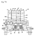
- FIG. 7A illustrates a modification of the die block 10 shown in FIG. 3A.
- the die block 85 holds a two-piece rigid die 86 and a two-piece movable one Die 87.
- the dies 86, 87 are perpendicular to the plane of the drawing Plane divided into upper and lower parts 86a, 86b of the rigid die 86 and upper and lower parts 87a, 87b of the movable die 87.
- the standard dimension of the cross section of the matrices 86, 87 is the parting line between the two Divide 86a, 87a and 86b, 87b so chosen that this undersize of the workpiece always still on the top and bottom of the inserted into the matrices 86, 87 workpiece abutment (viewed in the direction of impact shown in the drawing plane of FIG. 7A of FIG runs down to the top).
- a tuning plate 88 arranged with a conical inlet opening, so that at a automatic feed the workpiece to be separated safely into the movable die is introduced.
- the movable die 87 is at the lower part 87 b with a phase 89 provided so that also the insertion of the workpiece from the rigid Matrix 86 is relieved.
- the matrices are on a foundation 90 stored, which in turn is applied to a base of the impact machine, as they For example, in Fig. 1A is shown.
- the matrices are between die cheeks 91 (see also plan view Fig. 7C) and are within the matrix block 85th replaceable, so that an adaptation to changed workpiece cross-sections ensured is.
- the adjustment of the cross section of the rigid die 86 by means of a tool in the direction of conveyance slidable wedge 92, which is displaced by a displacement unit 93 becomes.
- the wedge 92 acts with a ramp-shaped bottom 86 c (see Fig. 9) of the lower part 86b of the die together, so that by shifting of the wedge 92, the lower die part 86b is lowered or raised.
- the direction of displacement of the wedge 92 is only an example and the raising or lowering of the lower female part 86b and the upper female part 86a may also be otherwise done by means of an adjustment.
- the wedge 92 For inserting or conveying the work to be processed Workpiece is withdrawn in the illustrated embodiment, the wedge 92 to the left, so that the lower die part 86b lowers down.
- the movable die 87 rests on a damping piston 95, which in turn over a carrier or distribution plate 96 on the spring ring assembly 98 as a damping element rests.
- the spring ring assembly 98 here comprises three concentric circles of Spring ring sets, each having a different number of spring ring-individual elements include.
- the spring ring assembly 98 rests on a pressure plate 99, which in turn is bolted to the base 90 from below. When screwing the Pressure plate 99 is the spring ring assembly 98 between pressure plate 99 and foundation 90 and a predetermined by the compression path biasing force set.
- the hydraulic cylinder 100 acts via the Piston rod on the support plate 96 both for lifting the die 87 and for applying a bias to the die 87 during impact. It supports the hydraulic cylinder 100, the damping of the displacement of the movable die 87th
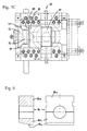
- Figures 7C and 7B show a plan view of the die block 85 and an entrance side View.
- Fig. 8 shows an entrance-side view of the two-part, movable Die 87 and
- FIG. 9 show an entrance-side view and a cross-sectional view the rigid matrix 86.
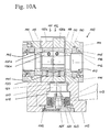
- FIG. 10A shows a lateral cross-sectional view 10a through an axis along the feed of a to be separated Workpiece
- Fig. 10B shows a cross-sectional view in plan view
- Fig. 10C shows a side cross-sectional view in the plane in which a rigid die 111 and a movable die 112 of the die block 110 abut one another.
- the die block 110 is the same as the die blocks shown in Figs. 3A and 7A 10 and 85 match. There are therefore only differing elements in the following or arrangements described in detail while those of the above Matrizenblöcken known elements are shown only briefly.
- Arrangement occurs to be separated rod material from the left into the opening of the matrix block 110, coming from the left initially a left end plate 140, a tuning plate 113, the rigid die 111, the movable die 112, and a pressure plate 114 and the right end plate 140 are arranged.
- Function of the tuning plate 113 and the pressure plate 114 is on the corresponding Elements 88 and 99 of Fig. 7A referenced.
- the matrices 111, 112 supported by die cheeks 116 (top view Fig. 10B).
- a damping piston 117 In a foundation 115 are a damping piston 117, a support plate 118, a spring ring assembly 119, a pressure plate 120, a hydraulic cylinder 121, a hydraulic supply line 122 for operating of the cylinder 121 and a step plate 123 for supporting the spring rings 119 different height, and a guide ring 124 is arranged. Regarding the function of the elements 117 to 124 is applied to the corresponding function of the elements 95 to 100 at the die block 85 (FIG. 7A).
- the rigid matrix 111 is composed from outside to inside from a first outer ring 130a, in which a first inner ring 131 a is inserted.
- first inner ring 131 a In the first inner ring 131 a are turn three inner segments 132a arranged, see.
- the mobile is Die 112 composed of a second outer ring 130b, a second therein Inner ring 131b and the inner segments 132b.
- each of the three inner segments 132a, 132b turn a broken by a column ring, wherein each used in the gaps between the inner segments 132a, 132b O-rings 134 are.
- the O-rings serve to align the segments with each other during assembly and on the other hand pushing apart the inner segments 132a, 132b, when this at the periphery of the first and second inner ring 131a, 131 b released be (see below).
- the first and the second inner ring 131a, 131b are respectively between the first and second outer ring 130a, 130b and the inner segments 132a, 132b axially displaceable stored.
- the outer surface of the inner ring 131a, 131b forms with the inner surface of the Outer ring 130a, 130b an axially parallel guide surface for axial displacement.
- the inner surface of the inner ring 131a, 131b has with respect to the outer surface of Inner segments 132a, 132b a ramp-like course, so that with axial displacement of the inner ring, the inner segments 132a, 132b like a collet in the radial direction be pushed together or released. Referring to Fig.
- the 10A causes a displacement of the first inner ring 131a to the right, a compression the inner segments 132a to each other, so that the opening cross-section for receiving the reduced bar material is reduced.
- the movable die 112 causes a displacement of the second inner ring 131b to the left also a compression the inner segments 132b against each other while reducing the opening cross-section.
- the first inner ring 131 a is moved to the left and the O-rings 134 between the inner segments 132a push the inner segments apart.
- Figs. 10B and 10C are on both sides of the die block Pages for releasing a clamped workpiece each have a return hydraulics 150 arranged.
- a return hydraulics 150 In the side cheeks 116 of the die block 110 are cylinder elements 151 recessed, in each case a piston 152 hydraulically in forward and Reverse direction is actuated.
- a return dome 153 In the piston 152, a return dome 153 is inserted, which is passed between the two outer rings 130a, 130b and in a wedge-shaped depression engages the outer edge between the inner segments 132a, 132b.
- the die block 110 is opened in the upper half Position shown while closed in the lower half of the drawing Position is shown.
- the movable die 112 is in the open position shown while the rigid die 111 is shown in clamping position.
- Fig. 11 shows schematically a further embodiment of a die 160, instead of the rigid dies 86, 111 and / or the movable dies 87, 112 in the die block 85 and 110 is arranged and also has a variable cross-section.
- the die 160 surrounds the opening 164 for receiving the workpiece on the whole Scope except for a gap 161, which preferably extends radially.
- the gap 161 has on the outside a conical shape, so that an expanding mandrel 163 by a hydraulic unit 162 retracted into the gap or moved out of this can. By the retraction or extension of the expanding mandrel, the gap is changeable, so that the opening cross section 164 can be slightly changed.
- Gap and the opening cross-section formed so that when retracted expanding mandrel 163, the die clamps a workpiece located in the opening 164, too if, for example, by manufacturing tolerances of the workpiece, a lower limit the cross-sectional area of the workpiece is reached.
- the die 160 is in the clamping position and in the In case of the movable die, there is no feedback between the die movement and the hydraulic unit 162.
- the expansion mandrel 163 is first retracted so far into the gap 161, so that even when reaching the upper manufacturing tolerance of the cross section of Workpiece or rod material allows a pinch-free feed in the axial direction becomes. After the feed of the rod material of the spreader 163 is again withdrawn from the gap 161.
- the upper and lower halves of the die 160 adjacent to the gap 161 are so connected to an actuating unit that the gap of the gap 161 opposite the relaxed state is expandable and / or reducible. By the operating unit will also during the execution of the separation impact an additional clamping force transferred to the die 160 by reducing the gap.
- Fig. 12 shows a schematic cross-sectional view through a successive one Arrangement 170 of three die elements 171, 172, 173.
- a first rigid Die 171 and a second rigid die 174 is a movable die 172 arranged.
- a damping element 173 is between the movable die 172 and a Base 175 .
- the damping element 173 can according to the damping elements described in the other embodiments be educated.
- one, several or all of the matrices 171, 172 and 174 with a variable cross section according to the embodiments may be formed in FIGS. 7A, 10A or 11 - correspondingly, one, several or all matrices have a solid cross-section.
- the die assembly 170 is particularly suitable for cutting rod material when repeated rod material with the same, relatively short length L should be cut to length.
- the depth the movable die 172 corresponding to the desired length L of the workpiece educated.
- the feed length 2L advanced so that after separating the rod material respectively at the edges between the first fixed die 171 and the movable die 172 and the Edge between the movable die 172 and the second fixed die 174 two Workpieces each having the length L are separated. Due to the symmetry of Separation becomes a more even load on the tool or die block reached during the separation stroke, so that the die block dimensioned weaker can be or the wear of the matrix block is lower.
- FIG. 13 illustrates a die block 180 as a modification of the die block 110 of FIG Fig. 10A dar.
- the clamping hydraulics 140-147 on the right side of Fig. 10A all elements are to the die block 110 are identical and therefore will not be further described here.
- the right Stim plate 140 of the matrix block 180 are arranged clamping discs 181 and 182, whose non-opposite side surfaces are flat.
- the left side surface of the first clamping washer 181 acts on the bronze bolt 143 and the right side surface of the second clamping plate 182 abuts the end plate 140.
- the opposing ones Side surfaces of the clamping disks 181, 182 have paired, helical or helical contact surfaces.
- the clamping discs can rotate each other, while the outer side surface are parallel to each other and the left side surface the first clamping plate 181, the bolt 143 synchronously to the left shifts.
- the bolts 143 act on the second inner ring 131b passing therethrough the inner segments 132b moves inward (see above for clamping a Workpiece at die block 110).
- the die blocks shown above are stored in an impact cutter when used advantageous on a support structure of mineral cast to the transfer of To dampen shockwaves.
Landscapes
- Engineering & Computer Science (AREA)
- Mechanical Engineering (AREA)
- Perforating, Stamping-Out Or Severing By Means Other Than Cutting (AREA)
- Shearing Machines (AREA)
- Electrophonic Musical Instruments (AREA)
- Shovels (AREA)
- Extrusion Of Metal (AREA)
- Turning (AREA)
- Presses And Accessory Devices Thereof (AREA)
Abstract
Die Erfindung betrifft eine Schneideeinheit (85) für eine Schlagschneidevorrichtung mit zumindest einem ersten und einem zweiten Matrizenelement (86, 87) zum Aufnehmen eines zu bearbeitenden Werkstücks, wobei zumindest eines der Matrizenelemente (87) relativ zu dem anderen Matrizenelement (86) oder den anderen Matrizenelementen beweglich gelagert ist und zumindest eines der Matrizenelemente (86, 87) einen veränderbaren Querschnitt zur Aufnahme des Werkstücks aufweist. Weiterhin wird ein Matrizenelement (86, 87) mit veränderbarem Aufnahmequerschnitt für ein Werkstück vorgeschlagen. <IMAGE>The invention relates to a cutting unit (85) for a percussion cutting device having at least a first and a second die element (86, 87) for receiving a workpiece to be machined, wherein at least one of the die elements (87) relative to the other die element (86) or the other Matrizenelementen is movably mounted and at least one of the die elements (86, 87) has a variable cross-section for receiving the workpiece. Furthermore, a template element (86, 87) with a variable receiving cross section for a workpiece is proposed. <IMAGE>
Description
Die Erfindung betrifft eine Schneideeinheit, insbesondere für eine Schlagschneidevorrichtung zum adiabatischen Trennen von Werkstücken, und ein Matrizenelement für eine solche Schneideeinheit.The invention relates to a cutting unit, in particular for a striking cutting device for adiabatic cutting of workpieces, and a die element for such a cutting unit.
Beim Hochgeschwindigkeits-Schlagschneiden wird ein hoher Impuls auf eine bewegliche Matrize übertragen, die durch den Impuls lateral gegen eine starre Matrize verschoben wird. Zwischen den Matrizen ist in einem Durchgang durch die Matrizen das Werkstück eingespannt, wobei deren Querschnitt dem des zu trennenden Werkstücks entspricht. Die Beobachtungen zeigen, dass das zu schneidende Werkstück bei sehr kurz, aber heftig einwirkendem Impuls nahezu ohne plastische Verformung trennbar ist. Dabei wird die verschiebbare Matrize lediglich um wenige zehntel Millimeter gegenüber der starren Matrize versetzt. Problematisch ist hierbei einerseits, einen reproduzierbaren Impuls mit genauer Stärke auf die bewegliche Matrize zu übertragen, und andererseits die Impulsenergie, die nicht in Trennenergie umgewandelt wurde, so zu dämpfen, dass die Schlagschneidevorrichtung auch für den Dauereinsatz geeignet ist.In high-speed impact cutting, a high impulse becomes a movable impulse Transfer matrix, which is laterally displaced by the pulse against a rigid die becomes. Between the matrices, the workpiece is in one pass through the matrices clamped, wherein the cross section corresponds to that of the workpiece to be separated. The observations show that the workpiece to be cut is very short, but violently acting impulse is separable with almost no plastic deformation. there The displaceable die is compared only by a few tenths of a millimeter offset the rigid die. The problem here is on the one hand, a reproducible To transmit pulse with exact power to the movable die, and on the other hand the pulse energy, which was not converted into separation energy, so to dampen that the impact cutting device is also suitable for continuous use.
In der DE 695 19 238 T2 (entsprechend EP 0 833 714 B1) ist eine Schlagmaschine beschrieben, bei der das Werkstück zwischen einer starren und einer beweglichen Matrize eingespannt ist. Auf der beweglichen Matrize ruht ein Schlagbolzen, auf den mittels eines hydraulisch bewegten Kolbens ein Schlagimpuls übertragen wird. Ziel ist es hier, eine möglichst hohe Schlagrate zu erreichen, so dass beispielsweise eine hohe Schneiderate von Drahtstiften bestimmter Länge erreicht wird. Zur Erreichung der hohen Schlagrate durch den hydraulisch betätigten Kolben wird eine spezielle Kolben/Zylinderanordnung vorgeschlagen.DE 695 19 238 T2 (corresponding to EP 0 833 714 B1) describes a striking machine, when the workpiece between a rigid and a movable die is clamped. On the movable die rests a firing pin, on the means a hydraulically moved piston is transmitted a shock pulse. The goal here is To achieve the highest possible rate of impact, so that, for example, a high cutting rate is reached by wire pins of a certain length. To achieve the high rate of impact by the hydraulically operated piston is a special piston / cylinder assembly proposed.
Auch die US 4,840,236 schlägt einen hydraulisch-pneumatischen Aktuator zur Übertragung hoher Impulse auf ein zu komprimierendes oder zu schneidendes Werkstück vor. Neben einer Zylindergestaltung für eine hohe Beschleunigung des Kolbens wird auch eine Anordnung zur Abbremsung des Kolbens vorgeschlagen.Also US 4,840,236 proposes a hydraulic-pneumatic actuator for transmission high pulses on a workpiece to be compressed or cut. In addition to a cylinder design for a high acceleration of the piston will also proposed an arrangement for deceleration of the piston.
Es ist Aufgabe der Erfindung, eine Schneideeinheit, eine Schlagschneidevorrichtung und ein Matrizenelement vorzusehen, die beim Schlagschneiden eine hohe Trennpräzision bzw. Standfestigkeit auch bei häufiger Schlagwiederholung gewährleisten.It is an object of the invention, a cutting unit, a punch cutting device and to provide a die element which has a high cutting precision in impact cutting or ensure stability even with frequent repeats.
Diese Aufgabe wird mit den Merkmalen des Anspruchs 1, 13, 16 bzw. 17 gelöst. Vorteilhafte
Ausgestaltungen sind Gegenstand der Unteransprüche.This object is achieved with the features of
Die Querschnittsfläche der Matrizenelemente ist herkömmlich auf die Außenkonturen des zu trennenden Werkstücks angepasst, wobei toleranzbedingt ein Spiel zwischen der Matrizenelement-Innenwandung und der Werkstück-Außenwandung vorhanden sein muss. Aufgrund dieses Spiels kommt es insbesondere bei längeren Werkstücken zu einem Winkelversatz des innerhalb des Matrizenelements gelagerten Werkstücks während der Schlagphase und Bewegung des beweglichen Matrizenelements, so dass die Schnittfläche gegenüber der ursprünglichen Ausrichtung des Werkstücks in den Matrizenelementen leicht schräg verlaufen kann.The cross-sectional area of the die elements is conventional on the outer contours adjusted to the workpiece to be separated, with tolerance due to a game between the Matrizenelement inner wall and the workpiece outer wall be present got to. Due to this game it comes in particular for longer workpieces to a Angular offset of the stored within the die element workpiece during the flapping phase and movement of the movable die element, so that the cut surface against the original orientation of the workpiece in the die elements can be slightly inclined.
Es wird daher gemäß Anspruch 1 oder 16 vorgeschlagen, dass das bewegliche Matrizenelement,
das ruhend gelagerte Matrizenelement oder beide Matrizenelemente einen
veränderbaren Querschnitt zur Aufnahme des Werkstücks aufweisen.It is therefore proposed according to
Ganz besonders vorteilhaft ist der Querschnitt in Schlagrichtung verkleinerbar, so dass durch Verkleinern des Querschnitts in Schlagrichtung vor dem Schlag (vorzugsweise das ruhend gelagerte Matrizenelement) oder während der Schlagphase (vorzugsweise das bewegliche Matrizenelement) der Querschnitt auf den tatsächlichen Querschnitt des Werkstücks angepasst wird. Dies verhindert einen Winkelversatz der Fläche zu der ursprünglichen Ausrichtung des zu bearbeitenden Werkstücks. Somit ermöglicht der veränderbare Querschnitt zumindest in Schlagrichtung eine tatsächliche Anlage des Matrizenelements an der Außenseite des Werkstücks.In a particularly advantageous embodiment, the cross section can be made smaller in the direction of impact, so that by reducing the cross section in the direction of impact before impact (preferably the resting mounted die element) or during the beating phase (preferably the movable die element) the cross section on the actual cross section of Workpiece is adjusted. This prevents an angular offset of the surface to the original one Alignment of the workpiece to be machined. Thus, the changeable allows Cross section at least in the direction of impact an actual system of the die element on the outside of the workpiece.
Vorteilhaft ist eine Klemm- oder Spannvorrichtung vorgesehen, mit der der veränderbare Querschnitt vor und während des Ausführens des Trennschlages verringerbar ist, so dass das zu trennende Werkstück spielfrei in dem Matrizenelement aufgenommen ist. Das Klemmen oder Spannen kann bei dem beweglichen und/oder dem festen Matrizenelement erfolgen. In weiterer Ausgestaltung ist eine Rückstelleinrichtung vorgesehen, mit der die mittels der Klemm- oder Spannvorrichtung bewirkte Klemmung des Werkstücks nach dem Trennen lösbar ist.Advantageously, a clamping or clamping device is provided with which the variable Cross section before and during the execution of the separation stroke is reducible, so that the workpiece to be separated is received without play in the die element. Clamping or clamping may occur with the movable and / or fixed die element respectively. In a further embodiment, a restoring device is provided, with the clamping of the workpiece effected by means of the clamping or tensioning device is detachable after separation.
In Ausgestaltung ist eines oder sind beide Matrizenelemente zumindest zweiteilig aufgebaut, so dass eine Relativbewegung der Einzelteile eines Matrizenelements eine Anlage desselben an der Außenfläche des Werkstücks ermöglicht. Besonders vorteilhaft ist das Matrizenelement zumindest quer zur Schlagrichtung getrennt, wobei vorteilhaft gegenüber einem einteiligen Matrizenelement, dessen Querschnittfläche die Toleranz des Werkstücks berücksichtigt, die Höhe der Trennfuge so bemessen ist, dass diese ungefähr die Differenz zwischen dem größten Querschnitt des Werkstücks und dem kleinsten Querschnitt des Werkstücks beträgt.In one embodiment, one or both die elements are constructed at least in two parts, so that a relative movement of the individual parts of a die element an attachment the same on the outer surface of the workpiece allows. Is particularly advantageous the die element separated at least transversely to the direction of impact, wherein advantageous opposite a one-piece die element whose cross-sectional area is the tolerance of the workpiece, the height of the parting line is dimensioned so that this approximately the difference between the largest cross-section of the workpiece and the smallest Cross section of the workpiece is.
Vorteilhaft weist ein Matrizenelement mit veränderbarem Querschnitt gegeneinander verstellbare Innensegmente auf, wobei zwischen jeweils zwei Innensegmenten ein elastisches Element angeordnet ist, die insbesondere unter Vorspannung zwischen den Innensegmenten geklemmt sind. Dadurch werden die Innensegmente voneinander getrennt und ein Werkstück freigegeben, sobald die Klemmung der Innensegmente freigegeben ist. Vorteilhaft ist zumindest eines der Innensegmente mittels einer Verdrehsicherung gegen Verdrehung gesichert.Advantageously, a matrix element with a variable cross-section against each other adjustable inner segments, wherein between each two inner segments an elastic Element is arranged, in particular under bias between the inner segments are clamped. As a result, the inner segments are separated from each other and released a workpiece as soon as the clamping of the inner segments released is. It is advantageous at least one of the inner segments by means of a rotation secured against rotation.
Bei einer weiteren Ausgestaltung weist zumindest ein Matrizenelement einen von der Aufnahmeöffnung für das zu trennende Werkstück ausgehenden Spalt mit veränderbarem Spaltmaß auf. Vorteilhaft ist eine Betätigungseinrichtung zum Verändern des Spaltmaßes vorgesehen. Vorteilhaft ist das Spaltmaß durch die Betätigungseinrichtung und/oder das Einführen des zu bearbeitenden Werkstücks erweiterbar ist.In a further embodiment, at least one die element has one of Receiving opening for the workpiece to be separated outgoing gap with changeable Gap on. Advantageously, an actuating device for changing the Gap provided. The gap is advantageous by the actuator and / or the insertion of the workpiece to be machined is expandable.
Bei der Schneideeinheit gemäß Anspruch 9 ist zwischen einem beweglichen Matrizenelement und einer Stützstruktur für die Schneideeinheit eine Dämpfungseinrichtung zwischen der der Schlagseite der beweglichen Matrize gegenüberliegenden Seite und der Stützstruktur angeordnet. Diese Anordnung kann auch bei einem Matrizenelement ohne veränderbarem Öffnungsquerschnitt zur Aufnahme des Werkstücks vorgesehen sein (vgl. Anspruch 17). Mit dem Dämpfungselement wird überschüssige Energie vom Schlag gedämpft, falls die Schlagenergie nicht vollständig in Trennenergie und Wärmeenergie überführt werden konnte. Somit wird die Ausbreitung überschüssiger Schlagenergie, die gerade bei toleranzbehafteten Werkstücken von Schlag zu Schlag stark variieren kann, auf einen möglichst kleinen Teilbereich des Schneidewerkzeugs begrenzt und eine Ausbreitung auf eine Schneidvorrichtung weitgehend verhindert.In the cutting unit according to claim 9 is between a movable die element and a support structure for the cutting unit, a damping device between the side opposite the flip side of the movable die and arranged the support structure. This arrangement can also be applied to a die element provided without changeable opening cross-section for receiving the workpiece be (see claim 17). With the damping element is excess energy from Shock damped if the impact energy is not completely in separation energy and heat energy could be transferred. Thus, the spread of excess impact energy, which vary greatly with workpieces subject to tolerances from beat to beat can be limited to the smallest possible portion of the cutting tool and largely prevents propagation to a cutting device.
Ganz besonders vorteilhaft ist das Dämpfungselement in Schlagrichtung vorgespannt mit einer Vorspannung, die vorzugsweise von der Stärke des zu bearbeitenden Werkstücks abhängt. Durch die Vorspannung verschiebt sich das bewegliche Matrizenelement mit Aufsetzen des Schlagelements auf die Oberseite der beweglichen Matrize nicht unmittelbar, sondern die bewegliche Matrize wird zunächst zwischen dem Schlagelement und der Unterlage (Dämpfungselement) eingespannt mit einer Kraft bis zur Höhe der Vorspannung. Erst wenn die Vorspannung überwunden ist, setzt sich das bewegliche Matrizenelement in Bewegung und die weitere Schlagenergie wird dann durch die adiabatische Trennung und gegebenenfalls weitere Dämpfung durch das Dämpfungselement umgesetzt. Durch die Klemmung des beweglichen Matrizenelements zwischen Schlageinrichtung und Dämpfungselement wird eine stabilisierende Ausrichtung des beweglichen Matrizenelements innerhalb der Schneideinheit erreicht. Besonders bei Verwendung eines beweglichen Matrizenelements mit veränderbarem Querschnitt bewirkt die Klemmung zunächst eine spielfreie Anlage der Matrizeninnenflächen (in Schlagrichtung) an der Außenfläche des Werkstücks, so dass ein Verkanten des Werkstücks mit Einsetzen der Bewegungsphase des beweglichen Matrizenelements verhindert wird.Most advantageously, the damping element is biased in the direction of impact with a bias, preferably on the strength of the workpiece to be machined depends. Due to the bias, the movable die element shifts with fitting of the impact element on the top of the movable die not immediately, but the movable die is first between the striking element and the pad (damping element) clamped with a force up to Height of preload. Only when the preload is overcome, the movable sits Die element in motion and the further impact energy is then through the adiabatic separation and optionally further damping by the damping element implemented. By clamping the movable die element between Impact device and damping element becomes a stabilizing orientation of the movable die element within the cutting unit. Especially at Use of a movable Matrizenelements effected with variable cross-section the clamping first a play-free system of Matrizeninnenflächen (in Impact direction) on the outer surface of the workpiece, allowing tilting of the workpiece prevents the onset of the movement phase of the movable die element becomes.
Ist eine Einstellbarkeit der Vorspannung am Dämpfungselement mittels einer Vorspanneinrichtung vorgesehen, so lässt sich die Klemmkraft in Abhängigkeit der Stärke oder der Formgebung des zu bearbeitenden Werkstücks anpassen. Vorteilhaft ist mittels einer Vorspanneinrichtung die Vorspannung am Dämpfungselement automatisch einstellbar, so dass während des laufenden Produktionsbetriebs eine Anpassung oder Optimierung der Vorspannung ermöglicht ist. Die Vorspanneinrichtung kann dabei die Vorspannung des Dämpfungselements erhöhen und/oder verringern. Vorteilhaft umfasst die Dämpfungseinrichtung einen Luftspalt umfasst, in den insbesondere Pressluft mit vorgegebenem Druck und/oder Durchfluss einleitbar ist.Is an adjustability of the bias voltage on the damping element by means of a biasing device provided, so can the clamping force in dependence of the strength or the shape of the workpiece to be machined. Is advantageous by means a biasing device, the bias on the damping element automatically adjustable, so that during the ongoing production operation an adjustment or optimization the bias is enabled. The biasing device can be the Increase and / or reduce the pretensioning of the damping element. Advantageously the damping device comprises an air gap, in particular compressed air with predetermined pressure and / or flow can be introduced.
Ganz besonders vorteilhaft wird mittels einer Ringfeder als Dämpfungseinrichtung die Überschussenergie innerhalb einer sehr kurzen Strecke in Wärmeenergie umgewandelt. Ist zusätzlich oder alternativ ein Luftspalt als Dämpfungseinrichtung vorgesehen und wird in den Luftspalt Pressluft eingeleitet, so werden einerseits Verunreinigungen aus dem Luftspalt abgeführt und andererseits dient die kontinuierliche Luftströmung zum Kühlen der Schneideeinheit.Very particularly advantageous is by means of an annular spring as a damping device the Excess energy converted into heat energy within a very short distance. Is additionally or alternatively provided an air gap as a damping device and If compressed air is introduced into the air gap, impurities are released on the one hand the air gap dissipated and on the other hand serves the continuous air flow to Cooling the cutting unit.
Ist die bewegliche Matrize in einer Ausnehmung mit seitlicher Führung gelagert, so führt die in den Luftspalt zugeführte Luft ebenfalls zur Rückstellung des beweglichen Matrizenelements. Dies lässt sich dadurch unterstützen, dass bei ausgelenktem Matrizenelement die Luft aus dem Luftspalt nahezu nicht entweichen kann, und sich so ein Luftdruck aufbaut, der die Matrize mit erhöhter Kraft zurückstellt.Is the movable die mounted in a recess with lateral guidance, so The air supplied into the air gap also leads to the return of the movable Of matrix. This can be supported by the fact that with deflected die element the air from the air gap almost can not escape, and so on Builds air pressure, which resets the matrix with increased force.
Ist zumindest das eine bewegliche Matrizenelement in einer Aufnahme mit seitlichen Begrenzungsflächen gelagert und werden die seitlichen Begrenzungsflächen mit Luft beaufschlagt, so werden einerseits Verunreinigungen daraus abgeführt, und das Luftpolster dient als Luftleitlager der Führung des beweglichen Matrizenelements in der Aufnahme. Weitet sich bei dem beweglichen Matrizenelement der Öffnungsquerschnitt von der Trennkante zur Zufuhr- oder Entnahmeseite des Werkstücks auf, so muss während des Schlagvorgangs nicht das gesamte, in der Matrize gefasste Werkstück die seitlich ausgeführte Beschleunigung ausführen. Damit erhöht sich die an der Schneidestelle wirkende Impulsenergie.Is at least the one movable die element in a receptacle with lateral Boundary surfaces are stored and the lateral boundary surfaces with air impinged on the one hand impurities are discharged therefrom, and the air cushion serves as an air guide bearing the leadership of the movable die element in the Admission. Expands in the movable die element of the opening cross-section from the cutting edge to the supply or removal side of the workpiece, so must during the impact process not the entire, in the female workpiece taken laterally perform executed acceleration. This increases the at the cutting point acting pulse energy.
Bei der Schlagschneidevorrichtung gemäß Anspruch 14 wird vorgeschlagen, dass das
Schlagelement, welches den Impuls auf eine Schneideeinheit überträgt, lösbar an eine
Beschleunigungseinheit gekoppelt ist. Vor dem Auftreffen des Schlagelements auf die
Schneideeinheit erfolgt durch eine Kopplungseinrichtung eine Entkopplung zwischen
Beschleunigungseinheit und Schlagelement. Durch Entkoppeln der Vorgänge 'Schlagen'
und 'Beschleunigen' kann jeweils der Schlagprozess und der Beschleunigungsprozess
unabhängig voneinander optimiert werden, wobei vor allem durch die Entkopplung der
Beschleunigungseinheit vom Schlagen diese wesentlich geringeren mechanischen Belastungen
unterliegt. Weiterhin kann die Beschleunigung genau dann abgebrochen werden,
wenn das Schlagelement den für das zu bearbeitende Werkstück notwendigen Impuls
aufweist, so dass z.B. das Abbremsen der Beschleunigungseinheit wiederum nicht
auf das Schlagelement und dessen Impuls zurückwirkt. Durch die freie 'Flugstrecke' des
Schlagelements vor der Schneideeinheit ist auch eine exakte Justierung zwischen Beschleunigungseinheit
und Schneideeinheit zur Reproduzierung eines vorgegebenen
Schlagimpulses nicht notwendig.In the impact cutting device according to
Ganz besonders vorteilhaft greift ein Mitnehmer der Beschleunigungseinheit in das Schlagelement ein und führt dieses zumindest während der Beschleunigungsphase bzw. über die Beschleunigungsstrecke mit. Über den Mitnehmer wird einerseits die Beschleunigungskraft auf das Schlagelement übertragen und andererseits eine sichere Führung des Schlagelements erreicht. Die Kopplung 'zumindest' über eine Beschleunigungsstrecke bedeutet hier, dass entweder der Mitnehmer lediglich während der Beschleunigungsphase bzw. über die Beschleunigungsstrecke an das Schlagelement gekoppelt ist und nach der Beschleunigung unmittelbar eine Entkopplung stattfindet. Oder es wird noch eine vorgegebene Zeit bzw. Strecke nach der Beschleunigung eine Kopplung aufrechterhalten, so dass der Mitnehmer kraftfrei an das Schlagelement koppelt. Very particularly advantageous engages a driver of the acceleration unit in the Impact element and performs this at least during the acceleration phase or over the acceleration section with. About the driver on the one hand, the acceleration force transferred to the striking element and on the other hand a secure leadership achieved the impact element. The coupling 'at least' over an acceleration section here means that either the driver only during the acceleration phase or coupled to the impact element via the acceleration section is and immediately takes place after the acceleration decoupling. Or It is still a predetermined time or distance after acceleration a coupling maintained so that the driver coupled force-free to the impact element.
Anhand von Zeichnungen werden Ausführungsformen der Erfindung erläutert. Es zeigen:
- Fig. 1A
- eine schematische Vorderansicht einer Schlagschneidemaschine,
- Fig. 1B
- eine Teilansicht der Schlagschneidemaschine beim Einkoppeln des Hammers,
- Fig. 1C
- eine Teilansicht der Schlagschneidemaschine kurz vor dem Entkoppeln des Hammers,
- Fig. 1D
- eine Seitenansicht der Schlagschneidemaschine,
- Fig. 2
- einen schematischen Querschnitt einer Hammereinheit von oben,
- Fig. 3A
- und 3B Querschnittsansichten einer Ausführung eines Matrizenblockes,
- Fig. 4A
- und 4B zwei Ausführungsformen von Dämpfungselementen,
- Fig. 5
- eine schematische Seitenansicht einer Doppelschlag-Schneidemaschine,
- Fig. 6
- ein Blockschema der Steuerung einer Schlagschneidemaschine,
- Fig. 7A
- eine Querschnittsansicht durch eine weitere Ausführung eines Matrizenblocks,
- Fig. 7B
- eine eintrittseitige Ansicht des Matrizenblocks von Fig. 7A,
- Fig. 7C
- eine Draufsicht auf den Matrizenblock von Fig. 7A,
- Fig. 8
- eine eintrittseitige Ansicht und Querschnittsansicht des beweglichen Matrizenelements,
- Fig. 9
- eine eintrittseitige Ansicht und Querschnittsansicht des starren Matrizenelements,
- Fig. 10A - 10C
- Querschnittsansichten einer weiteren Ausführung eines Matrizenblocks,
- Fig. 11
- eine weitere Ausführung einer Matrize mit veränderbarem Querschnitt,
- Fig. 12
- eine schematische Ansicht der Aneinanderreihung von drei Matrizen für eine Doppeltrennung,
- Fig. 13
- eine Querschnittsansicht einer weiteren Aufführung des Matrizenblocks von Fig. 10A, und
- Fig. 14
- Spannscheiben für den Matrizenblock von Fig. 13.
- Fig. 1A
- a schematic front view of a percussion cutting machine,
- Fig. 1B
- a partial view of the impact cutting machine when coupling the hammer,
- Fig. 1C
- a partial view of the impact cutting machine just before the decoupling of the hammer,
- Fig. 1D
- a side view of the impact cutting machine,
- Fig. 2
- a schematic cross section of a hammer unit from above,
- Fig. 3A
- and FIG. 3B are cross-sectional views of an embodiment of a die block. FIG.
- Fig. 4A
- and FIG. 4B two embodiments of damping elements,
- Fig. 5
- a schematic side view of a double-dash cutting machine,
- Fig. 6
- a block diagram of the control of a percussion cutting machine,
- Fig. 7A
- a cross-sectional view through a further embodiment of a template block,
- Fig. 7B
- an entrance-side view of the matrix block of Fig. 7A,
- Fig. 7C
- a top view of the die block of Fig. 7A,
- Fig. 8
- an entrance-side view and cross-sectional view of the movable die element,
- Fig. 9
- an entrance-side view and cross-sectional view of the rigid die element,
- 10A-10C
- Cross-sectional views of another embodiment of a matrix block,
- Fig. 11
- a further embodiment of a template with a variable cross section,
- Fig. 12
- a schematic view of the juxtaposition of three matrices for a double separation,
- Fig. 13
- a cross-sectional view of another embodiment of the die block of Fig. 10A, and
- Fig. 14
- Clamping disks for the die block of FIG. 13.
Die bisherigen Schlagschneider sind darauf optimiert, ein Werkstück (meist ein bestimmtes Ausgangsmaterial und mit einer vorgegebenen Materialstärke in Drahtform) mit sehr hoher Schlagrate zu trennen, so dass viele Drahtstifte für die Weiterverarbeitung erzeugt werden können. Beim Einrichten der Maschine wird das System durch Versuche so optimiert, dass einerseits eine saubere Materialtrennung eintritt und andererseits eine möglichst geringe Umwandlung des Schlagimpulses in Schockwellen innerhalb des Gerätes auftritt. Durch die anschließend lange Nutzung der Maschine mit den optimierten Parametern ist die Optimierungszeit gerechtfertigt. Bei häufig wechselnder Werkstückart (Materialform, Materialstärke, verwendetes Material etc.) oder Abweichungen bei der Materialbeschaffenheit (Formfehler, Toleranzen, Lage des Materials in der Schneideeinrichtung, Lunker etc.) ist jedoch eine solche Optimierungsphase nicht gerechtfertigt.The previous impact cutters are optimized to a workpiece (usually a specific Starting material and with a given material thickness in wire form) with very high stroke rate, allowing many wire pens for further processing can be generated. When setting up the machine, the system goes through Experiments optimized so that on the one hand a clean material separation occurs and on the other hand the lowest possible conversion of the impact pulse into shock waves within of the device occurs. By the then long use of the machine with the optimized parameters justify the optimization time. For frequently changing Type of workpiece (material shape, material thickness, material used, etc.) or Deviations in the material quality (form errors, tolerances, position of the material in the cutting device, voids, etc.), however, is such an optimization phase not justified.
Daher wird einerseits angestrebt, eine Änderung des Impulses des Schlagelements und die Optimierung der Schlagenergie auf möglichst einfache, reproduzierbare Weise zu erreichen. Dies ist aufgrund der dynamischen Prozesse in einem pneumatischen oder hydraulischen System sehr aufwändig und hängt von der Öltemperatur, vom verwendeten Öl, dessen Verschmutzung, der Abnutzung von Dichtelementen und dergleichen ab. Darüber hinaus sind bei den herkömmlichen Schlagschneidern das bewegte Schlagelement und die Beschleunigungseinrichtung auch während der Schlagphase miteinander verbunden, so dass einerseits die Beschleunigungseinheit mechanisch entsprechend stabil ausgelegt sein muss und andererseits einer starken mechanischen Beanspruchung unterliegt, die zum schnellen Verschleiß führen kann.Therefore, on the one hand strives to change the momentum of the striking element and optimizing impact energy in the simplest, most reproducible way to reach. This is due to the dynamic processes in a pneumatic or Hydraulic system very complex and depends on the oil temperature, used by Oil, its pollution, the wear of sealing elements and the like. Moreover, in the conventional impact cutters, the moving striking element and the accelerator also during the beat phase with each other connected, so that on the one hand, the acceleration unit mechanically stable accordingly must be designed and on the other hand, a strong mechanical stress subject to rapid wear.
Fig. 1A zeigt schematisch eine Vorderansicht des Aufbaus einer Schlagschneidemaschine
1. Das zu schneidende Werkstück 2 (Fig. 1C) ist in einen Matrizenblock 10 eingespannt
und wird dort durch Ausübung von Schlägen mittels der Hammereinheit 20
geschnitten. Ein Prallhammer 21 der Hammereinheit 20 wird durch ein Beschleunigungsaggregat
30 beschleunigt. Der Matrizenblock 10 ruht auf einer Tragstruktur 31, an
die auch eine Führung 22 der Hammereinheit 20 und das Beschleunigungsaggregat 30
angekoppelt sind. Teile der Tragstruktur 31 sind aus Mineralguss ausgebildet, der neben
der hohen Trageigenschaft eine besonders gute Dämpfung gegen die Ausbreitung von
Schwingungen und Schockwellen aufweist. Eine Ausbreitung von Schwingungen oder
Schockwellen ausgehend vom Matrizenblock auf den Werkhallenboden bzw. auf das
Beschleunigungsaggregat 30 und die Hammereinheit 20 wird somit vermieden. Umgekehrt
wird auch die Ausbreitung von Schwingungen ausgehend von der Hammereinheit
20 stark gedämpft.Fig. 1A shows schematically a front view of the construction of a
Beim Beschleunigungsaggregat 30 verläuft eine Kette 32 über ein oberes Antriebsrad
33 und ein unteres Umlenkrad 34. Das obere Antriebsrad 33 wird durch einen NCgesteuerten
Servomotor 82 (Fig. 1D) angetrieben, der kurzzeitige, sehr hohe Beschleunigungen
ermöglicht. Die Kette 32 führt einen Schlitten 36a mit, von dem ein Mitnehmer
36 hervorsteht, der wiederum in eine Ausnehmung 28 des Hammers 21 eingreift.
Zumindest über einen Teil der Beschleunigungsstrecke verläuft neben der Kette 32 eine
Kettenführung 35. Die Kettenführung umfasst einen Aktuator, hier einen pneumatischen
Aktuator, der eine neben der Kette verlaufende Kettenführungsschiene senkrecht zur
Kette zustellt. In der Beschleunigungsphase ist die Kettenführungsschiene der Kette
beigestellt (wie in Fig. 1A dargestellt) und begrenzt bzw. dämpft seitliche, senkrecht zur
Zugrichtung auftretende Kettenausschläge die durch die Beschleunigung bzw. das spätere
Abbremsen hervorgerufen werden könnten. Die Kontaktfläche der Kettenführungsschiene
zur Kette ist mit einem Gleitmaterial versehen.When accelerating
Zum Einführen des Mitnehmers 36 in die Ausnehmung 28 beim Ankoppeln des Hammers
21 ist die Kettenführung zurückgezogen, so dass die Kette seitlich ausgelenkt werden
kann: Fig. 1B stellt eine Teilansicht der Schlagschneidemaschine in einer Phase
kurz vor dem Einkoppeln des Mitnehmers 36 in die Ausnehmung 28 des Hammers dar.
Der Hammer ist durch eine Hebeeinheit 37 nach dem Schlag in die in Fig. 1B dargestellte
Position angehoben und der Schlitten 36a wird durch die Kette 33 nach oben gefahren.
Fig. 1C zeigt eine Phase während der Beschleunigung, während der der Mitnehmer
36 vollständig in die Ausnehmung 28 des Hammers 21 eingreift.For inserting the
Bei einer hier nicht dargestellten Ausführung wird die Kette 32 alternativ oder zusätzlich
durch das untere Rad 34 angetrieben, so dass die Kette zwischen dem unteren und
oberen Rad 34, 35 über die Beschleunigungsstrecke gespannt und versteift ist.In an embodiment not shown here, the
Fig. 2 zeigt eine schematische Querschnittsansicht der Hammereinheit 20 von oben. Der
Hammer 21 ist in einer ersten und zweiten Führungsschiene 23, 24 der Führung 22 geführt.
Der Hammer 21 steht nicht unmittelbar mit den Führungsschienen 23, 24 in Berührung,
sondern wird über Gleitblöcke 26, die in Vertiefungen 25 ruhen, an den Schienen
22, 23 gleitend geführt. Die Gleitblöcke 26 sind beispielsweise Metallmatrizen, in
die Molybdänsulfid (MoS) als Gleitmittel eingelagert ist. Zwischen der Rückseite der
Gleitblöcke 26 und dem Boden der Vertiefung 25 sind Dämpfungselemente 27 angeordnet,
die Impulse des Hammers 21 in Wärme umsetzen und damit die Übertragung
von Schwingungen oder Schockwellen vom Hammer 21 auf die Schienen 23, 24 dämpfen.
Bei einer weiteren, hier nicht dargestellten Ausgestaltung können auch allen oder
einem Teil der Seitenwände zwischen dem Gleitblock 26 und der Vertiefung 25 Dämpfungselemente
zugeordnet sein. Der Mitnehmer 36 des Beschleunigungsaggregats 30
weist seitliche Vorsprünge auf, die über einen Steg mit dem Schlitten 36a verbunden
sind. Die beiden seitlichen Vorsprünge des Mitnehmers 36 greifen in die beiden seitlichen
Ausnehmungen 28 am Hammer 21 ein. An die Seitenwände der Ausnehmungen
28 schließen Rampen 29 an, wobei die Vorsprünge des Mitnehmers 36 beim Zurückführen
des Hammers 21 aus der unteren Position (beim Matrizenblock 10) über die Rampe
29 gleiten. Dabei werden die Kette 32 und der Schlitten 36a ausgelenkt (Fig. 1B) und
nach Erreichen der Ausnehmung 28 springen die Vorsprünge des Mitnehmers 36 in die
Ausnehmung 28, so dass der Hammer 21 durch das Beschleunigungsaggregat 30 angehoben
und in seine Startposition zurückgeführt werden kann.FIG. 2 shows a schematic cross-sectional view of the
Fig. 3A zeigt einen Werkzeughalter 11 des Matrizenblocks 10 im Querschnitt. In eine
von oben nach unten führende Ausnehmung des Werkzeughalters 11 sind eine starre
Matrize 12 und eine bewegliche Matrize 13 austauschbar eingesetzt. Das Matrizenpaar
12, 13 hat einen ersten und zweiten Durchgang 14, 15, deren Querschnitt jeweils auf das
zu bearbeitende Werkstück angepasst ist. Zum Schneiden eines Werkstücks einer anderen
Beschaffenheit (Querschnitt, Material des Werkstücks, Form des Werkstücks usw.)
wird jeweils das Matrizenpaar 12, 13 im Werkzeughalter 11 ausgetauscht. Durch nicht
dargestellte Befestigungselemente wird die starre Matrize 12 fest im Werkzeughalter 11
gehalten, während unterhalb der beweglichen Matrize 13 eine Vertiefung 18 angeordnet
ist, die während des Schlags eine geringe Bewegung der Matrize 13 nach unten erlaubt.
Der Hammer 21 und/oder die Matrizen 12, 13 sind aus einem besonders schlagfesten
Stahl ausgebildet, beispielsweise von der Firma STM-Stahl das Produkt der Kennnummer
1.2379 (Spezialstahl). Durch die Pfeile 16 und 17 sind die Eintrittsseite und die
Austrittsseite des Werkstücks 1 am Werkzeughalter 11 dargestellt, wobei natürlich ein
umgekehrtes Einführen und Entnahme des Werkstücks ebenso möglich ist. Der gebogene
Pfeil symbolisiert die Ausführung des Schlags auf die bewegliche Matrize 13.FIG. 3A shows a
Der zweite Durchgang 15 der beweglichen Matrize 13 weitet sich von der Schnittstelle
zur Eintritts- bzw. Austrittsseite 17 hin auf. Dadurch ist einerseits das Werkstück im
Bereich der Schnittkante spielfrei gefasst, während bei längeren Werkstücken ein Versetzen
des Endes des Werkstücks außerhalb der Matrize 13 beim Schlagschneiden vermieden
wird. Dadurch reduziert sich die während des Schlags zu beschleunigende Masse
und die aufzubringende Impulsenergie ist bei längeren Werkstücken weitgehend unabhängig
von der Länge des abzutrennenden Werkstücks. The
In der Vertiefung 18 ist ein Dämpfungselement 19 angeordnet, das den Schlagimpuls
bzw. den Teil des Schlagimpulses, der nicht in Trennungs- und Deformationsenergie
beim Schlag umgewandelt wurde, auffängt und in Wärme umwandelt. Das Dämpfungselement
19 setzt einer Verschiebung der beweglichen Matrize 13 eine sehr hohe Kraft
entgegen, so dass diese auch bei Vorhandensein von Überschussenergie innerhalb einer
sehr kurzen Auslenkungsstrecke vollständig abgebremst wird. Fig. 4A und 4B zeigen
zwei Ausführungsbeispiele für das Dämpfungselement 19. Der erste Federring 51 ist
aus fünf ineinander verkeilten, geschlossenen Ringelementen ausgebildet. Die so ausgebildete
Reibungsfeder setzt die Verschiebung der Ringe durch Reibung in Wärmeenergie
um und bewirkt eine effiziente Dämpfung der beweglichen Matrize 13. Mit 52 ist
eine zweite Federringanordnung bezeichnet, bei der die Ringe teilweise übereinander
und untereinander positioniert sind, so dass die Grundfläche der Ausnehmung 18 weiter
ausgenutzt wird.In the
Nach Ausführung eines Schlags auf das bewegliche Matrizenelement 13 erfolgt die
Rückstellung der Matrize 13 durch das Dämpfungselement 19. Alternativ oder zusätzlich
kann wie in Fig. 3A dargestellt, die Rückstellung durch Aufbau eines Druckluftpolsters
unterhalb des ausgelenkten Matrizenelements 13 ausgeführt werden. In die Vertiefung
18 wird, wie durch die Pfeile 55 symbolisiert, Druckluft eingeleitet, die bei angehobenem
Matrizenelement 13 durch einen Auslass 57 entweicht. Bei abgesenktem
Matrizenelement 13 wird der Luftauslass 57 ganz oder teilweise verschlossen, so dass
sich in der Vertiefung 18 aufgrund der durch die unteren Druckluftdurchgänge 55 eingeleiteten
Druckluft ein Druck aufbaut, der die Matrize 13 wieder in ihre Ausgangsstellung
anhebt. Der Druckluftstrom von den Druckluftdurchgängen 55 durch die Vertiefung
18 verhindert ein Eindringen von Verunreinigungen in die Vertiefung 18 und kühlt
das Dämpfungselement 19 bzw. die untere Matrizenseite. Bei einer weiteren Ausgestaltung
sind an zumindest einer seitlichen Fläche zwischen Werkzeughalter 11 und beweglicher
Matrize 13 Luftspalte ausgebildet, in die über seitliche Luftdurchgänge 56 Luft
einströmt. Die Druckluft zwischen beweglicher Matrize und Werkzeughalter 11 richtet
die bewegliche Matrize 13 aus und ermöglicht während des Schlags ein seitliches Gleiten
und danach ein Rückstellen der beweglichen Matrize 13 in die Ausgangsstellung. After execution of a blow on the
Zusätzlich ist dem Werkzeughalter 11 ein Sensor 58 zugeordnet, der die Schwingungen
des Werkzeughalters 11 registriert und/oder den Luftdruck in der Vertiefung 18 misst.
Damit lassen sich während der Ausführung des Schlages das Vorhandensein und die
Höhe von Schwingungen messen. Die Höhe der Schwingungen ist ein Maß für die überschüssige
Schlagenergie, die nicht zum Trennen des Werkstücks umgewandelt wurde.
Da die überschüssige Energie möglichst vermieden werden muss, dient das Signal
des Sensors 58 zur Optimierung der Parameter der Schlagschneidemaschine sowie zur
Kontrolle der Funktion des Schlagschneidens. Wird wie in Fig. 3A dargestellt, ein der
Vertiefung 18 zugeordneter Drucksensor verwendet, so kann auch die einwandfreie
Rückstellung der beweglichen Matrize 13 bei Einleitung von Druckluft in die Vertiefung
18 überprüft werden, wobei nach Rückstellung der Matrize 13 in die Ausgangsposition
der Druck innerhalb der Vertiefung 18 auf einen vorgegebenen Wert abfallen
muss.In addition, the
Fig. 3B zeigt eine Ausführung eines Druckluftdurchgangs 55 und/oder 56, wobei mehrere
solcher Bohrungen im Werkzeughalter 11 über die Fläche verteilt vorgesehen sind,
so dass sich ein gleichmäßiges Luftpolster ausbildet. Wird ein Lochdurchmesser von
einigen Mikrometern (10 - 200 µm) verwendet, so kann bei Komprimierung der Luft in
den Spalten oder in der Vertiefung 18 die Druckluft nicht schnell genug durch die Bohrungen
55, 56 entweichen und bei Auslenkung stellt sich ein hoher Luftdruck in den
Spalten und/oder der Vertiefung 18 ein.Fig. 3B shows an embodiment of a
Fig. 5 zeigt schematisch die Anordnung einer Doppelschlag-Schneidemaschine 60. Bei
dieser Anordnung ist eine Schneideeinheit 61 schwimmend oder zumindest in Schlagrichtung
in beide Richtungen auslenkbar in einem hier nicht dargestellten Werkzeughalter
gelagert. Eine erste und zweite Matrize 62, 63 sind dabei gegeneinander und bzgl.
des Werkzeughalters verschiebbar. Wie in Fig. 5 dargestellt, wird das Werkstück von
oben eingeführt und die abgelenkten Teile nach unten entnommen. Die Orientierung ist
hier nur beispielhaft. Die Matrizen 62, 63 sind über ein erstes und zweites Dämpfungselement
64, 65 gegeneinander gelagert. Ein erster und ein zweiter Hammer 69, 70 werden
bevorzugt auf einer gemeinsamen Schwerpunktsachse gegeneinander beschleunigt,
wobei vorteilhaft auch die Schwerpunktsachse der Matrizen 62, 63 mit derjenigen der
Hämmer 69, 70 übereinstimmt. Ein Beschleunigungsaggregat 66 beschleunigt den ersten
und zweiten Hammer 69, 70 über eine erste und zweite Beschleunigungsstrecke 67,
68. Die Beschleunigung der Hämmer 69, 70 erfolgt derart, dass deren Impulse gleich
sind. Zur einfacheren Dimensionierung und Einstellung sind vorzugsweise die Gewichte
der Hämmer 69, 70 gleich. Symbolhaft wird durch den Riemen 71 angedeutet, dass
die Beschleunigung über die erste und zweite Beschleunigungsstrecke 67, 68 synchron
zueinander erfolgt. Dabei kann beispielsweise ein gemeinsamer Antrieb verwendet werden,
der über ein Getriebe, eine Kette oder dergleichen beide Beschleunigungsstrecken
miteinander koppelt. Das Entkoppeln der Hämmer 69, 70, die Führung der Hämmer
und/oder die Beschleunigung über die Beschleunigungsstrecken 67, 68 erfolgt dabei
vorteilhaft entsprechend obigen Ausführungen zur einfachen Beschleunigungsstrecke
der Fig. 1.Fig. 5 shows schematically the arrangement of a double-dash cutting machine 60. Bei
In this arrangement, a cutting
Fig. 6 zeigt schematisch die Steuerung der Schlagschneidemaschine 1 (oder 61+66)
durch eine Steuereinheit 80. An der Steuereinheit 80 werden die Betriebsparameter eingegeben,
wie beispielsweise die Art der Matrize und des zu schneidenden Materials, so
dass auf vorgegebene Parametersätze mit jeweils einer Standardeinstellung entsprechend
der Matrizen und des zu schneidenden Materials zurückgegriffen werden kann.
Die Steuereinheit 80 steuert einen Leistungssteller 81 an, der die elektrische Energie für
einen Motor 82 zum Antrieb bereitstellt, um beispielsweise das obere Antriebsrad 33
anzutreiben. Die Steuereinheit 80 stellt dabei die Startposition für das Beschleunigen
des Hammers 21 ein und steuert die Stärke der Beschleunigung (ggf. zeitlich über die
Beschleunigungsstrecke variierbar), gegebenenfalls den Endpunkt der Beschleunigung
(so dass bereits vor dem Entkoppeln eine Relaxation zwischen Hammer 21 und Mitnehmer
36 eintritt) und das Rückführen des Mitnehmers zum Rückstellen des Hammers
21 in seine Startposition für den nächsten Schlagvorgang. Weiterhin wird durch die
Steuereinheit 80 eine Fördereinheit 83 angesteuert, die die Zuführung des abzuschneidenden
Ausgangsmaterials in den Werkzeughalter 11 bewirkt. Zur Optimierung des
Schlagprozesses wird das Sensorsignal des Sensors 58 der Steuereinheit 80 zugeführt,
so dass diese anhand der Stärke der Überschussenergie (siehe oben) den Prozess durch
Einstellen der Beschleunigungsparameter so lange optimieren kann, bis die Überschussenergie
minimal ist. 6 shows schematically the control of the impact cutting machine 1 (or 61 + 66)
by a
Die Beschleunigung des Hammers 21 (entsprechend gilt dies auch für die Hämmer 69,
70) erfolgt derart, dass der Hammer bzw. Mitnehmer 36 in der Anfangsposition ist und
der Beschleunigungsvorgang mittels des Motors 82 startet. Dabei kann auch bei kleinen,
erforderlichen Schlagimpulsen (beispielsweise bei einem dünnen Werkstück) von einer
maximalen Auslenkungsposition gestartet werden, um über eine lange Beschleunigungsstrecke
bei geringer Beschleunigungsstärke beschleunigen zu können. Ist dagegen
eine hohe Schlagzahl erforderlich, so wird entsprechend dem notwendigen Schlagimpuls
eine möglichst kurze Beschleunigungsstrecke (niedrige Startposition des Hammers
21) gewählt, so dass der Beschleunigungs- und Rückstellvorgang in kurzer Zeit ausführbar
ist. Dabei wirkt dann eine hohe Beschleunigung auf den Hammer ein.The acceleration of the hammer 21 (this also applies to the
In Höhe des unteren Umlenkrads führt das Umlenken der Kette 32 zum Zurückziehen
des Schlittens 36a und damit zum Herausfahren des Mitnehmers 36 aus der Ausnehmung
28 (z.B. Fig. 5). Schon nach kurzer Umlenkung des Schlittens 36a (kleiner Umlenkwinkel
am Umlenkrad 34) ist der Mitnehmer 36 aus der Ausnehmung 28 herausgezogen
und die Bewegung des Hammers 21 setzt sich ungehindert in Richtung Matrizenblock
10 fort. Zum Anheben des Hammers 21 in die Startposition wird der Hammer 21
nach Ausführung des Schlags durch den in Fig. 1A dargestellten Anhebmechanismus 37
entweder synchron zum Zurückfahren des Mitnehmers 36 angehoben, so dass durch das
Anheben des Hammers 21 und das Hochfahren des Mitnehmers 36 der Mitnehmer in
die Vertiefung 28 eingreift, oder der Hammer 21 wird durch den Hebemechanismus auf
eine Höhe oberhalb des unteren Umlenkrads 34 angehoben, so dass die Vorsprünge des
Mitnehmers 36 über die untere Rampe 29 gleiten und durch Beiseitedrücken der Kette
32 (Phase Fig. 1B) die Vorsprünge des Mitnehmers nach der Rampe in die Ausnehmung
28 eingreifen. Wie oben erwähnt, wird in dieser Phase durch den Aktuator der
Kettenführung 35 die Kettenführungsschiene von der Grundlinie der Kette 32 zurückgezogen.
Nach Eingreifen des Mitnehmers 36 in die Ausnehmung 28 lässt sich der Hammer
21 durch das Beschleunigungsaggregat 30 in die Startposition zurückfahren.At the level of the lower deflection wheel, the deflection of the
Fig. 7A stellt eine Abwandlung des in Fig. 3A dargestellten Matrizenblockes 10 dar.
Der Matrizenblock 85 fasst eine zweiteilige starre Matrize 86 und eine zweiteilige bewegliche
Matrize 87. Die Matrizen 86, 87 sind in der senkrecht zur Zeichenebene stehenden
Ebene geteilt in einen oberen und unteren Teil 86a, 86b der starren Matrize 86
und einen oberen und unteren Teil 87a, 87b der beweglichen Matrize 87. Gegenüber
dem Normmaß des Querschnitts der Matrizen 86, 87 ist die Trennfuge zwischen beiden
Teilen 86a, 87a und 86b, 87b so gewählt, dass diese bei Untermaß des Werkstücks immer
noch an der Ober- und Unterseite des in die Matrizen 86, 87 eingeschobenen Werkstücks
anliegen (betrachtet in Schlagrichtung, die in der Zeichenebene von Fig. 7A von
oben nach unten verläuft). In Einführrichtung (von links) ist vor der starren Matrize 86
eine Abstimmplatte 88 mit konischer Eintrittsöffnung angeordnet, so dass bei einem
automatischen Vorschub das zu trennende Werkstück sicher in die bewegliche Matrize
eingeführt wird. Eintrittsseitig ist die bewegliche Matrize 87 am unteren Teil 87b mit
einer Phase 89 versehen, so dass ebenfalls das Einführen des Werkstücks von der starren
Matrize 86 kommend erleichtert ist. Die Matrizen sind auf einem Grundstock 90
gelagert, der wiederum auf einen Sockel der Schlagmaschine aufgepratzt ist, wie sie
beispielsweise in Fig. 1A dargestellt ist. Die Matrizen sind zwischen Matrizenwangen
91 (siehe auch Draufsicht Fig. 7C) gefasst und sind innerhalb des Matrizenblocks 85
austauschbar, so dass eine Anpassung an veränderte Werkstückquerschnitte gewährleistet
ist.FIG. 7A illustrates a modification of the
Die Einstellung des Querschnitts der starren Matrize 86 erfolgt mittels eines in Werkzeugförderrichtung
verschiebbaren Keils 92, der durch eine Verschiebeeinheit 93 verschoben
wird. Der Keil 92 wirkt mit einer rampenförmig ausgebildeten Unterseite 86c
(siehe Fig. 9) des unteren Teils 86b der Matrize zusammen, so dass durch Verschieben
des Keils 92 der untere Matrizenteil 86b abgesenkt oder angehoben wird. Die Verschieberichtung
des Keils 92 ist hier nur beispielhaft und das Anheben bzw. Absenken des
unteren Matrizenteils 86b bzw. des oberen Matrizenteils 86a kann auch auf andere Weise
mittels einer Verstelleinheit erfolgen. Zum Einlegen bzw. Fördern des zu bearbeitenden
Werkstücks wird in der dargestellten Ausführung der Keil 92 nach links zurückgezogen,
so dass sich der untere Matrizenteil 86b nach unten absenkt. Damit öffnet sich
der Querschnitt in Schlagrichtung der starren Matrize 86 und die Verschiebbarkeit des
Werkstücks im Öffnungsquerschnitt ist gegeben. Nach Positionierung des Werkstücks
wird der Keil 92 wieder nach rechts verschoben, so dass eine Klemmung des Werkstücks
oben und unten erfolgt.The adjustment of the cross section of the
Die bewegliche Matrize 87 ruht auf einem Dämpfungskolben 95, der wiederum über
eine Träger- bzw. Verteilungsplatte 96 auf der Federringanordnung 98 als Dämpfungselement
ruht. Die Federringanordnung 98 umfasst hier drei konzentrische Kreise von
Federringsätzen, die jeweils eine unterschiedliche Anzahl von Federring-Einzelelementen
umfassen. Die Federringanordnung 98 ruht auf einer Druckplatte 99,
die wiederum von unten an den Grundstock 90 angeschraubt ist. Beim Anschrauben der
Druckplatte 99 wird die Federringanordnung 98 zwischen Druckplatte 99 und Grundstock
90 komprimiert und eine durch den Kompressionsweg vorgegebene Vorspannspannkraft
eingestellt. Hierbei wird die Federringanordnung 98 zwischen der Druckplatte
99 und dem Anschlag 97 am unteren Ende des Dämpfungskolben 95 komprimiert.
Wird ein Schlag auf die Oberseite des oberen Matrizenteils 87a ausgeführt, so wird zunächst
das Werkstück zwischen den oberen und unteren Matrizenteil 87a, 87b geklemmt,
bis eine der Vorspannung der Federringanordnung 98 entsprechende Gegenkraft
aufgebaut ist, wonach sich dann die bewegliche Matrize 87 mit dem eingespannten
Werkstück nach unten bewegt.The
Ein unterhalb der beweglichen Matrize 87 angeordneter Hydraulikzylinder 100 hebt die
bewegliche Matrize 87 an, bis diese an einem Anschlag (nicht dargestellt) anliegt und in
dieser angehobenen Position mit der starren Matrize 86 fluchtet, d.h. die Öffnungen in
den Matrizen 86, 87 zur Aufnahme des zu trennenden Werkstücks sind deckungsgleich
nebeneinander positioniert. Nach der Ausführung des Trennschlages wird somit durch
den Zylinder 100 die Matrize 87 in die Ausgangsposition zurückgestellt. Eine durch den
Zylinder 100 betätigte Kolbenstange 101 ist durch eine Bohrung in der Trägerplatte 96
geführt und liegt nach dem Anheben direkt an der Unterseite der beweglichen Matrize
87 an. Während des Schlages zum Trennen ist die Kolbenstange 101 normalerweise
eingezogen. In einer weiteren Ausgestaltung wirkt der Hydraulikzylinder 100 über die
Kolbenstange auf die Trägerplatte 96 sowohl zum Anheben der Matrize 87 als auch
zum Anlegen einer Vorspannung an die Matrize 87 während des Schlages. Dabei unterstützt
der Hydraulikzylinder 100 die Dämpfung der Auslenkung der beweglichen Matrize
87.An arranged below the
Die Figuren 7C und 7B zeigen eine Draufsicht auf den Matrizenblock 85 und eine eintrittseitige
Ansicht. Die Fig. 8 zeigt eine eintrittseitige Ansicht der zweiteiligen, beweglichen
Matrize 87 und die Fig. 9 zeigt eine eintrittseitige Ansicht und Querschnittsansicht
der starren Matrize 86.Figures 7C and 7B show a plan view of the
Die Figuren 10A bis 10C zeigen Querschnittsansichten in verschiedenen Richtungen
durch ein weiteres Ausführungsbeispiels eines Matrizenblocks 110. Fig. 10A zeigt eine
seitliche Querschnittsansicht 10a durch eine Achse längs des Vorschubs eines zu trennenden
Werkstücks, Fig. 10B zeigt eine Querschnittsansicht in Draufsicht und Fig. 10C
zeigt eine seitliche Querschnittsansicht in der Ebene, in der eine starre Matrize 111 und
eine bewegliche Matrize 112 des Matrizenblocks 110 aneinanderliegen. Vom Grundaufbau
her stimmt der Matrizenblock 110 mit den in Fig. 3A und 7A dargestellten Matrizenblöcken
10 und 85 überein. Es werden daher im folgenden nur abweichende Elemente
oder Anordnungen detailliert beschrieben, während die aus den vorbeschriebenen
Matrizenblöcken bekannten Elemente nur kurz dargestellt sind. Bei der in Fig. 10A dargestellten
Anordnung tritt das zu trennende Stangenmaterial von links in die Öffnung
des Matrizenblocks 110 ein, wobei von links her kommend zunächst eine linke Stimplatte
140, eine Abstimmplatte 113, die starre Matrize 111, die bewegliche Matrize 112,
und eine Druckplatte 114 und die rechte Stimplatte 140 angeordnet sind. Bezüglich der
Funktion der Abstimmplatte 113 und der Druckplatte 114 wird auf die entsprechenden
Elemente 88 und 99 der Fig. 7A verwiesen. Seitlich werden die Matrizen 111, 112
durch Matrizenwangen 116 (Draufsicht Fig. 10B) gestützt. In einem Grundstock 115
sind ein Dämpfungskolben 117, eine Trägerplatte 118, eine Federringanordnung 119,
eine Druckplatte 120, ein Hydraulikzylinder 121, eine Hydraulikzuleitung 122 zum Betätigen
des Zylinders 121 und eine Stufenplatte 123 zum Stützen der Federringe 119
unterschiedlicher Höhe, sowie ein Führungsring 124 angeordnet. Bezüglich der Funktion
der Elemente 117 bis 124 wird auf die entsprechende Funktion der Elemente 95 bis
100 beim Matrizenblock 85 (Fig. 7A) verwiesen. Figures 10A to 10C show cross-sectional views in different directions
by another embodiment of a
Zum Klemmen des Stangenmaterials in den Öffnungen der Matrizen 111 und 112 weisen
diese einen geringfügig veränderbaren Öffnungsquerschnitt auf. Die starre Matrize
111 ist dabei von außen nach innen zusammengesetzt aus einem ersten Außenring 130a,
in den ein erster Innenring 131 a eingesetzt ist. Im ersten Innenring 131 a sind wiederum
drei Innensegmente 132a angeordnet, vgl. Seitenansicht der entsprechenden Innensegmente
132b der beweglichen Matrize 112 in Fig. 10C. Entsprechend ist die bewegliche
Matrize 112 zusammengesetzt aus einem zweiten Außenring 130b, darin einem zweiten
Innenring 131b und den Innensegmenten 132b. Zusammengesetzt bilden jeweils die
drei Innensegmente 132a, 132b wiederum einen durch Spalte unterbrochenen Ring, wobei
jeweils in den Spalten zwischen den Innensegmenten 132a, 132b O-Ringe 134 eingesetzt
sind. Die O-Ringe dienen einerseits der Ausrichtung der Segmente zueinander
bei der Montage und andererseits dem Auseinanderdrücken der Innensegmente 132a,
132b, wenn diese an deren Umfang vom ersten bzw. zweiten Innenring 131a, 131 b freigegeben
werden (siehe unten).For clamping the bar stock in the openings of the dies 111 and 112
this a slightly variable opening cross-section. The
Der erste und der zweite Innenring 131a, 131b sind jeweils zwischen dem ersten bzw.
zweiten Außenring 130a, 130b und den Innensegmenten 132a, 132b axial verschiebbar
gelagert. Die Außenfläche des Innenrings 131a, 131b bildet mit der Innenfläche des
Außenrings 130a, 130b eine axial parallel verlaufende Führungsfläche zum axialen Verschieben.
Die Innenfläche des Innenrings 131a, 131b hat bezüglich der Außenfläche der
Innensegmente 132a, 132b einen rampenartigen Verlauf, so dass bei axialer Verschiebung
des Innenrings die Innensegmente 132a, 132b spannzangenartig in radiale Richtung
zusammengeschoben oder freigegeben werden. Bezugnehmend auf Fig. 10A bewirkt
eine Verschiebung des ersten Innenrings 131a nach rechts ein Zusammendrücken
der Innensegmente 132a zueinander, so dass der Öffnungsquerschnitt zur Aufnahme des
abzulängenden Stangenmaterials verringert wird. Bei der beweglichen Matrize 112 bewirkt
ein Verschieben des zweiten Innenrings 131b nach links ebenfalls ein Zusammendrücken
der Innensegmente 132b gegeneinander unter Verringerung des Öffnungsquerschnitts.
Beim Vergrößern des Öffnungsquerschnitts, also beim Freigeben des geklemmten
Stangenmaterials, wird der erste Innenring 131a nach links verschoben und
die O-Ringe 134 zwischen den Innensegmenten 132a drücken die Innensegmente auseinander.
Umgekehrt wird zum Öffnen der beweglichen Matrize 112 der keilförmige
zweite Innenring 131b nach rechts verschoben, wobei die O-Ringe 134 die Innensegmente
132b auseinanderdrücken. Mittels eines Drehsicherungsrings 135 sind der Innenring
131a, 131b und das unterste der Innensegmente 132a, 132b am Außenring 130a,
130b gegen Verdrehung gesichert.The first and the second
Zum axialen Verschieben des ersten Innenrings 131a in Klemmrichtung (nach rechts)
bzw. des zweiten Innenrings 131b in Klemmrichtung (nach links) ist jeweils eine
Klemmhydraulik 147 zwischen der Stirnplatte 140 und einem Aufsatz 141 angeordnet.
Hydraulisch wird ein Schubkolben 142 zwischen der Stimplatte 140, dem Aufsatz 141
und einer Innenbuchse 146 in axiale Richtung verschoben. An der Innenseite des
Schubkolbens 142 sind über den Umfang der Innenringe 131a, 131b mehrere Schubbolzen
143 verteilt angeordnet (8 Stück entlang des Umfangs, wie der Fig. 10C entnommen
werden kann), die an der außenliegenden Seitenfläche der Innenringe 131a, 131b anliegen
und diese nach rechts (starre Matrize 111) bzw. links (bewegliche Matrize 112)
verschieben. Durch Druckbeaufschlagung von hinten wird der Schubkolben 142 zum
Klemmen nach vorne (in Richtung des Inneren des Matrizenblocks 110) verschoben.
Zum Lösen der Klemmung wird der Kolben rückseitig druckfrei gestellt und durch die
Innenringe 131 a, b in Richtung Aufsatz 141 zurückgeschoben. Die Abdichtung des
Schubkolbens 142 zwischen Aufsatz 141 und Stimplatte 140 erfolgt durch Dichtungen
144, 145. In weiterer, nicht dargestellter Ausführung kann der Kolben 142 beidseitig
hydraulisch betätigt vor- und zurückgeschoben werden.For axially displacing the first
Wie aus den Fig. 10B und 10C zu erkennen ist, sind seitlich am Matrizenblock auf beiden
Seiten zum Freigeben eines geklemmten Werkstücks jeweils eine Rückstellhydraulik
150 angeordnet. In den Seitenwangen 116 des Matrizenblocks 110 sind Zylinderelemente
151 eingelassen, in denen jeweils ein Kolben 152 hydraulisch in Vorwärtsund
Rückwärtsrichtung betätigbar ist. Im Kolben 152 ist ein Rückstelldom 153 eingesetzt,
der zwischen den beiden Außenringen 130a, 130b hindurchgeführt ist und in eine
keilförmige Vertiefung am Außenrand zwischen den Innensegmenten 132a, 132b eingreift.
Durch Vorschieben des Kolbens 152 schiebt sich die keilförmige Spitze des
Rückstelldoms 153 in die dreieckförmige Nut zwischen dem ersten und zweiten Innenring
131a, 131b und schiebt die Innenringe auseinander. Zum Lösen der Klemmung des
Werkstücks in den Öffnungen der Matrizen 111, 112 wird somit der Rückstelldom 153
vorgefahren und der erste Innenring 131 a nach links (Fig. 10A) sowie der zweite Innenring
132b nach rechts verschoben, wodurch die freigegebenen Segmente 132a, 132b den
Öffnungsquerschnitt erweitern. Der Kolben 152 ist durch Dichtungen 154, 155, 156 im
Zylinderelement 151 verschiebbar und dichtend gelagert. Nach dem Lösen der Klemmung
wird der Rückstelldom 153 durch Gegendruck am Kolben 152 zurückgefahren,
so dass nach dem Vorschub des Werkstücks erneut durch die Klemmhydraulik(en) 147
gespannt werden kann.As can be seen from Figs. 10B and 10C, are on both sides of the die block
Pages for releasing a clamped workpiece each have a
In der Draufsicht der Fig. 10B ist der Matrizenblock 110 in der oberen Hälfte in geöffneter
Stellung dargestellt, während er in der unteren Zeichnungshälfte in geschlossener
Stellung dargestellt ist. In Fig. 10A ist die bewegliche Matrize 112 in geöffneter Stellung
dargestellt, während die starre Matrize 111 in Klemmstellung dargestellt ist.In the plan view of Fig. 10B, the
Fig. 11 zeigt schematisch eine weitere Ausführung einer Matrize 160, die anstelle der
starren Matrizen 86, 111 und/oder der beweglichen Matrizen 87, 112 im Matrizenblock
85 bzw. 110 angeordnet ist und ebenfalls einen veränderlichen Querschnitt aufweist.
Die Matrize 160 umgibt die Öffnung 164 zum Aufnehmen des Werkstücks am gesamten
Umfang bis auf einen Spalt 161, der vorzugsweise radial verläuft. Der Spalt 161 hat
an der Außenseite einen konischen Verlauf, so dass ein Spreizdorn 163 durch eine Hydraulikeinheit
162 in den Spalt eingefahren oder aus diesem herausgefahren werden
kann. Durch das Ein- oder Ausfahren des Spreizdorns ist das Spaltmaß veränderbar, so
dass sich der Öffnungsquerschnitt 164 geringfügig verändern lässt. Vorteilhaft ist der
Spalt und der Öffnungsquerschnitt so ausgebildet, dass bei zurückgezogenem Spreizdorn
163 die Matrize ein in der Öffnung 164 befindliches Werkstück einklemmt, auch
wenn beispielsweise durch Fertigungstoleranzen des Werkstücks ein unterer Grenzwert
der Querschnittsfläche des Werkstücks erreicht wird. Während der Ausführung des
Schlages auf die bewegliche Matrize ist vorteilhaft der Spreizdorn 163 vollständig aus
dem Spalt 161 zurückgezogen. Dadurch ist die Matrize 160 in Klemmstellung und im
Falle der beweglichen Matrize erfolgt keine Rückkopplung zwischen der Matrizenbewegung
und der Hydraulikeinheit 162. Zum axialen Vorschub des Werkstücks bzw.
Stangenmaterials wird zunächst der Spreizdorn 163 so weit in den Spalt 161 eingefahren,
so dass auch bei Erreichen der oberen Fertigungstoleranz des Querschnitts des
Werkstücks oder Stangenmaterials ein klemmfreier Vorschub in axiale Richtung ermöglicht
wird. Nach dem Vorschub des Stangenmaterials wird der Spreizdom 163 wieder
aus dem Spalt 161 zurückgezogen. Bei einer weiteren, hier nicht dargestellten Ausführung
sind die an den Spalt 161 angrenzende obere und untere Hälfte der Matrize 160 so
mit einer Betätigungseinheit verbunden, dass das Spaltmaß des Spaltes 161 gegenüber
dem entspannten Zustand erweiterbar und/oder verringerbar ist. Durch die Betätigungseinheit
wird auch während der Ausführung des Trennschlages eine zusätzliche Klemmkraft
durch Verringerung des Spaltmaßes auf die Matrize 160 übertragen.Fig. 11 shows schematically a further embodiment of a
Fig. 12 zeigt eine schematische Querschnittsansicht durch eine hintereinanderliegende
Anordnung 170 von drei Matrizenelementen 171, 172, 173. Zwischen einer ersten starren
Matrize 171 und einer zweiten starren Matrize 174 ist eine bewegliche Matrize 172
angeordnet. In Schlagrichtung ist zwischen der beweglichen Matrize 172 und einem
Grundstock 175 ein Dämpfungselement 173 angeordnet. Das Dämpfungselement 173
kann entsprechend der zu den anderen Ausführungsbeispielen beschriebenen Dämpfungselemente
ausgebildet sein. Weiterhin können eine, mehrere oder alle der Matrizen
171, 172 und 174 mit einem veränderbaren Querschnitt gemäß den Ausführungsbeispielen
in den Fig. 7A, 10A oder 11 ausgebildet sein - enstprechend können eine, mehrere
oder alle Matrizen einen festen Querschnitt aufweisen. Die Matrizenanordnung 170
eignet sich besonders zur Ablängung von Stangenmaterial, wenn wiederholt Stangenmaterial
mit gleicher, relativ kurzer Länge L abgelängt werden soll. Dabei ist die Tiefe
der beweglichen Matrize 172 entsprechend der gewünschten Länge L des Werkstücks
ausgebildet. Beim Vorschub des Stangenmaterials wird jeweils um die Vorschublänge
2L vorgeschoben, so dass nach dem Trennen des Stangenmaterials jeweils an den Kanten
zwischen der ersten festen Matrize 171 und der beweglichen Matrize 172 sowie der
Kante zwischen der beweglichen Matrize 172 und der zweiten festen Matrize 174 zwei
Werkstücke mit jeweils der Länge L abgetrennt werden. Durch die Symmetrie der
Trennung wird eine gleichmäßigere Belastung des Werkzeugs bzw. des Matrizenblocks
während des Trennschlages erreicht, so dass der Matrizenblock schwächer dimensioniert
werden kann bzw. die Abnutzung des Matrizenblocks geringer ist. Fig. 12 shows a schematic cross-sectional view through a
Fig. 13 stellt einen Matrizenblock 180 als Abwandlung des Matrizenblockes 110 von
Fig. 10A dar. Abgesehen von den Spannscheiben 181, 182, die die Klemmhydraulik
140-147 auf der rechten Seite der Fig. 10A ersetzen, sind alle Elemente zum Matrizenblock
110 identisch und werden daher hier nicht weiter beschrieben. In der rechten
Stimplatte 140 des Matrizenblocks 180 sind Spannscheiben 181 und 182 angeordnet,
deren nicht gegenüberliegenden Seitenflächen eben sind. Die linke Seitenfläche der
ersten Spannscheibe 181 wirkt auf die Bronzebolzen 143 und die rechte Seitenfläche der
zweiten Spannscheibe 182 liegt an der Stimplatte 140 an. Die sich gegenüberstehenden
Seitenflächen der Spannscheiben 181, 182 weisen zueinander gepaarte, helix- oder
wendelförmige Anlageflächen auf. Wie in Fig. 14 in den beiden rechten Darstellungen
veranschaulicht, ändert sich das axiale Maß der beiden aufeinanderliegenden Spannscheiben,
wenn diese zueinander verschiedene Drehwinkel einnehmen. Bis zu einem
vorgegebenen Winkel (kleiner ca. 150°) lassen sich die Spannscheiben zueinander verdrehen,
während die äußeren Seitenfläche parallel zueinander stehen und die linke Seitenfläche
der ersten Spannscheibe 181 die Bolzen 143 synchron zueinander nach links
verschiebt. Die Bolzen 143 wirken wiederum auf den zweiten Innenring 131b, der dadurch
die Innensegmente 132b nach Innen verschiebt (siehe oben zum Klemmen eines
Werkstücks beim Matrizenblock 110).FIG. 13 illustrates a
Ähnlich der Wirkungsweise der Klemmhydraulik 140-147 auf der rechten Seite der Fig.
10A wird durch Drehen der ersten Spannscheibe 181 nach links (wenn man in der Zeichenebene
von Fig. 14 von links in axiale Richtung schaut) eine Klemmung des Werkstücks
erreicht, während durch eine Drehung nach rechts die Klemmung des Werkstücks
gelöst wird. Entsprechend gilt dies, wenn anstelle der ersten Spannscheibe 181
die zweite Spannscheibe 182 gedreht wird. Eine Betätigungseinrichtung zum Drehen
der rechten oder linken Spannscheibe ist vorgesehen, hier aber nicht weiter dargestellt.Similar to the operation of the clamping hydraulics 140-147 on the right side of FIG.
10A is turned to the left by turning the first tension pulley 181 (when in the plane of the drawing
from Fig. 14 from the left in the axial direction) a clamping of the workpiece
achieved while turning to the right, the clamping of the workpiece
is solved. Accordingly, this applies if instead of the
Die oben dargestellten Matrizenblöcke lagern beim Einsatz in einer Schlagschneidevorrichtung vorteilhaft auf einer Stützstruktur aus Mineralguss, um die Übertragung von Schockwellen zu dämpfen.The die blocks shown above are stored in an impact cutter when used advantageous on a support structure of mineral cast to the transfer of To dampen shockwaves.
Claims (17)
zumindest eines der Matrizenelemente relativ zu dem anderen Matrizenelement oder den anderen Matrizenelementen beweglich gelagert ist und
zumindest eines der Matrizenelemente einen veränderbaren Querschnitt zur Aufnahme des Werkstücks (2) aufweist.Cutting unit for a percussion cutting device (1, 60) having at least a first and a second die element (12, 13; 62, 63; 86, 87; 111, 112; 170, 171, 172) for receiving a workpiece (2) to be machined, in which
at least one of the die elements is movably mounted relative to the other die element or the other die elements, and
at least one of the die elements has a variable cross section for receiving the workpiece (2).
Priority Applications (2)
| Application Number | Priority Date | Filing Date | Title |
|---|---|---|---|
| US10/940,125 US20050072281A1 (en) | 2003-10-01 | 2004-09-14 | Cutting unit for an impact cutting device and matrix element therefor |
| US12/146,673 US20080257125A1 (en) | 2003-10-01 | 2008-06-26 | Cutting unit for an impact cutting device and matrix element therefor |
Applications Claiming Priority (2)
| Application Number | Priority Date | Filing Date | Title |
|---|---|---|---|
| DE10345864 | 2003-10-01 | ||
| DE10345864A DE10345864A1 (en) | 2003-03-04 | 2003-10-01 | Impact cutting device and cutting unit therefor |
Publications (3)
| Publication Number | Publication Date |
|---|---|
| EP1520649A2 true EP1520649A2 (en) | 2005-04-06 |
| EP1520649A3 EP1520649A3 (en) | 2005-05-18 |
| EP1520649B1 EP1520649B1 (en) | 2008-10-08 |
Family
ID=34306222
Family Applications (1)
| Application Number | Title | Priority Date | Filing Date |
|---|---|---|---|
| EP20040019642 Expired - Lifetime EP1520649B1 (en) | 2003-10-01 | 2004-08-18 | Cutting unit for an impact cutting device |
Country Status (4)
| Country | Link |
|---|---|
| US (2) | US20050072281A1 (en) |
| EP (1) | EP1520649B1 (en) |
| AT (1) | ATE410256T1 (en) |
| DE (1) | DE502004008193D1 (en) |
Cited By (3)
| Publication number | Priority date | Publication date | Assignee | Title |
|---|---|---|---|---|
| DE102005061600A1 (en) * | 2005-12-22 | 2007-07-05 | Helmut Schuster | Die element and cutting unit for a percussion cutting device |
| DE102007030328A1 (en) | 2007-06-29 | 2009-01-02 | Helmut Schuster | Damping device for diagonal cutting device that is utilized for cutting e.g. stainless steel bar, has chamber formed between base unit and fluid surface, and outlet with cross-sectional area for outputting fluid during piston axial stroke |
| WO2020074931A1 (en) * | 2018-10-12 | 2020-04-16 | Stamatis Gizelis S.A. | Electromechanical shears for vertical cutting |
Families Citing this family (2)
| Publication number | Priority date | Publication date | Assignee | Title |
|---|---|---|---|---|
| DE102009037396B4 (en) | 2009-08-13 | 2012-08-16 | Wafios Ag | Pyrotechnically operated cutting device |
| EP2505290B1 (en) * | 2011-03-28 | 2014-11-12 | Alstom Technology Ltd | Device and method for cutting the end winding of an electric machine |
Family Cites Families (15)
| Publication number | Priority date | Publication date | Assignee | Title |
|---|---|---|---|---|
| US1408184A (en) * | 1921-09-15 | 1922-02-28 | Brita R Farlow | Fruit-jar clamp and holder |
| US1932083A (en) * | 1927-08-06 | 1933-10-24 | Firestone Tire & Rubber Co | Band splicing machine |
| US2578404A (en) * | 1949-05-19 | 1951-12-11 | Charles F Dimitruk | Device for cutting bottle seals |
| US2718692A (en) * | 1953-04-14 | 1955-09-27 | Adam J Ciesielski | Bottle seal cutter and opening device |
| CH577865A5 (en) * | 1973-05-05 | 1976-07-30 | Hatebur Umformmaschinen Ag | |
| JPS52103363A (en) * | 1976-02-27 | 1977-08-30 | Ube Industries | Billet cutter |
| SU749578A1 (en) * | 1977-10-03 | 1980-07-23 | Предприятие П/Я А-1575 | Die for cutting tubes |
| US4635514A (en) * | 1985-05-03 | 1987-01-13 | Alexander Borzym | Elliptical shearing apparatus |
| DE220850T1 (en) * | 1985-10-22 | 1990-03-22 | Hallen Co., Houston, Tex. | CUTTER FOR BOTTLE CAPSULES. |
| IL78698A (en) * | 1986-05-06 | 1990-11-05 | Goldman Giora | Hydraulic-pneumatic actuator for impact cutter |
| GB8705096D0 (en) * | 1987-03-05 | 1987-04-08 | Mechatherm Eng Ltd | Shearing |
| EP0521230A1 (en) * | 1991-06-19 | 1993-01-07 | BALINT, Ludwig | Dispositif de découpe |
| JP2741351B2 (en) * | 1994-11-09 | 1998-04-15 | 旭サナック株式会社 | Material cutting device in forging machine |
| IT236898Y1 (en) * | 1995-05-24 | 2000-08-31 | Ghidini Cipriano S A S Di Dieg | CUTTING DEVICE TO REMOVE THE UPPER PART OF THE PLASTIC OR METAL ALLOY CAPS COVERING THE PLUG OF |
| ES2154341T3 (en) * | 1995-06-21 | 2001-04-01 | Hydropulsor Ab | PERCUSSION MACHINE |
-
2004
- 2004-08-18 EP EP20040019642 patent/EP1520649B1/en not_active Expired - Lifetime
- 2004-08-18 DE DE200450008193 patent/DE502004008193D1/en not_active Expired - Lifetime
- 2004-08-18 AT AT04019642T patent/ATE410256T1/en active
- 2004-09-14 US US10/940,125 patent/US20050072281A1/en not_active Abandoned
-
2008
- 2008-06-26 US US12/146,673 patent/US20080257125A1/en not_active Abandoned
Cited By (6)
| Publication number | Priority date | Publication date | Assignee | Title |
|---|---|---|---|---|
| DE102005061600A1 (en) * | 2005-12-22 | 2007-07-05 | Helmut Schuster | Die element and cutting unit for a percussion cutting device |
| EP1800781A3 (en) * | 2005-12-22 | 2008-10-01 | Helmut Schuster | Die element and cutting unit for an impact cutting device |
| DE102007030328A1 (en) | 2007-06-29 | 2009-01-02 | Helmut Schuster | Damping device for diagonal cutting device that is utilized for cutting e.g. stainless steel bar, has chamber formed between base unit and fluid surface, and outlet with cross-sectional area for outputting fluid during piston axial stroke |
| WO2020074931A1 (en) * | 2018-10-12 | 2020-04-16 | Stamatis Gizelis S.A. | Electromechanical shears for vertical cutting |
| US20210354215A1 (en) * | 2018-10-12 | 2021-11-18 | Stamatis Gizelis S.A | Electromechanical shears for vertical cutting |
| US11559841B2 (en) | 2018-10-12 | 2023-01-24 | Stamatis Gizelis S.A. | Electromechanical shears for vertical cutting |
Also Published As
| Publication number | Publication date |
|---|---|
| ATE410256T1 (en) | 2008-10-15 |
| EP1520649A3 (en) | 2005-05-18 |
| US20050072281A1 (en) | 2005-04-07 |
| US20080257125A1 (en) | 2008-10-23 |
| EP1520649B1 (en) | 2008-10-08 |
| DE502004008193D1 (en) | 2008-11-20 |
Similar Documents
| Publication | Publication Date | Title |
|---|---|---|
| EP0418779B1 (en) | Method for manufacture of workpieces by punching, in particular in a precision counter punching tool | |
| EP0968069B2 (en) | Machine tool | |
| DE2415549C3 (en) | Device for the non-cutting cold forming of a blank | |
| EP0425774A2 (en) | Control device for a tool or workpiece damper in a machine-tool spindle | |
| DE2334438B2 (en) | Production line for punching profiles | |
| EP0865853A1 (en) | Power actuated chuck | |
| EP0350516B1 (en) | Quick changing device for chucks | |
| EP1520649B1 (en) | Cutting unit for an impact cutting device | |
| DE102015103112B4 (en) | tool pusher | |
| EP0739663A2 (en) | Machine for forming workpieces | |
| DE102012212677B4 (en) | Honing tool, in particular for position honing | |
| DE2829681C2 (en) | Device for continuously punching holes in rod-shaped hollow bodies | |
| WO2000013833A1 (en) | Machining unit | |
| EP1601484B1 (en) | Impact cutting device | |
| DE102014102993B4 (en) | tool pusher | |
| DE19636139B4 (en) | Machine tool for drilling workpieces | |
| DE19531907A1 (en) | Device and method for producing profiled bodies | |
| DE19925029B4 (en) | Method for forming and apparatus for carrying out the method | |
| WO2005021253A2 (en) | Hydraulic press and deep-drawing press | |
| DE2632481C3 (en) | Machine for making center holes in the ends of bar material | |
| CH710982A1 (en) | Ring rolling device with axially fixed rolling bearings. | |
| DE102015119927B4 (en) | Method of machining a workpiece and linear hammer | |
| DE3314830C2 (en) | ||
| EP4355511B1 (en) | Method and forming device for producing annular molded parts | |
| EP2734327B1 (en) | Internal broaching machine |
Legal Events
| Date | Code | Title | Description |
|---|---|---|---|
| PUAI | Public reference made under article 153(3) epc to a published international application that has entered the european phase |
Free format text: ORIGINAL CODE: 0009012 |
|
| PUAL | Search report despatched |
Free format text: ORIGINAL CODE: 0009013 |
|
| AK | Designated contracting states |
Kind code of ref document: A2 Designated state(s): AT BE BG CH CY CZ DE DK EE ES FI FR GB GR HU IE IT LI LU MC NL PL PT RO SE SI SK TR |
|
| AX | Request for extension of the european patent |
Extension state: AL HR LT LV MK |
|
| AK | Designated contracting states |
Kind code of ref document: A3 Designated state(s): AT BE BG CH CY CZ DE DK EE ES FI FR GB GR HU IE IT LI LU MC NL PL PT RO SE SI SK TR |
|
| AX | Request for extension of the european patent |
Extension state: AL HR LT LV MK |
|
| 17P | Request for examination filed |
Effective date: 20051109 |
|
| AKX | Designation fees paid |
Designated state(s): AT BE BG CH CY CZ DE DK EE ES FI FR GB GR HU IE IT LI LU MC NL PL PT RO SE SI SK TR |
|
| 17Q | First examination report despatched |
Effective date: 20060330 |
|
| GRAP | Despatch of communication of intention to grant a patent |
Free format text: ORIGINAL CODE: EPIDOSNIGR1 |
|
| RTI1 | Title (correction) |
Free format text: CUTTING UNIT FOR AN IMPACT CUTTING DEVICE |
|
| GRAS | Grant fee paid |
Free format text: ORIGINAL CODE: EPIDOSNIGR3 |
|
| GRAA | (expected) grant |
Free format text: ORIGINAL CODE: 0009210 |
|
| AK | Designated contracting states |
Kind code of ref document: B1 Designated state(s): AT BE BG CH CY CZ DE DK EE ES FI FR GB GR HU IE IT LI LU MC NL PL PT RO SE SI SK TR |
|
| REG | Reference to a national code |
Ref country code: GB Ref legal event code: FG4D Free format text: NOT ENGLISH |
|
| REG | Reference to a national code |
Ref country code: CH Ref legal event code: EP |
|
| REG | Reference to a national code |
Ref country code: IE Ref legal event code: FG4D Free format text: LANGUAGE OF EP DOCUMENT: GERMAN |
|
| REF | Corresponds to: |
Ref document number: 502004008193 Country of ref document: DE Date of ref document: 20081120 Kind code of ref document: P |
|
| REG | Reference to a national code |
Ref country code: CH Ref legal event code: NV Representative=s name: KELLER & PARTNER PATENTANWAELTE AG WINTERTHUR |
|
| PG25 | Lapsed in a contracting state [announced via postgrant information from national office to epo] |
Ref country code: SI Free format text: LAPSE BECAUSE OF FAILURE TO SUBMIT A TRANSLATION OF THE DESCRIPTION OR TO PAY THE FEE WITHIN THE PRESCRIBED TIME-LIMIT Effective date: 20081008 |
|
| NLV1 | Nl: lapsed or annulled due to failure to fulfill the requirements of art. 29p and 29m of the patents act | ||
| PG25 | Lapsed in a contracting state [announced via postgrant information from national office to epo] |
Ref country code: BG Free format text: LAPSE BECAUSE OF FAILURE TO SUBMIT A TRANSLATION OF THE DESCRIPTION OR TO PAY THE FEE WITHIN THE PRESCRIBED TIME-LIMIT Effective date: 20090108 Ref country code: ES Free format text: LAPSE BECAUSE OF FAILURE TO SUBMIT A TRANSLATION OF THE DESCRIPTION OR TO PAY THE FEE WITHIN THE PRESCRIBED TIME-LIMIT Effective date: 20090119 |
|
| PG25 | Lapsed in a contracting state [announced via postgrant information from national office to epo] |
Ref country code: PT Free format text: LAPSE BECAUSE OF FAILURE TO SUBMIT A TRANSLATION OF THE DESCRIPTION OR TO PAY THE FEE WITHIN THE PRESCRIBED TIME-LIMIT Effective date: 20090218 Ref country code: PL Free format text: LAPSE BECAUSE OF FAILURE TO SUBMIT A TRANSLATION OF THE DESCRIPTION OR TO PAY THE FEE WITHIN THE PRESCRIBED TIME-LIMIT Effective date: 20081008 Ref country code: NL Free format text: LAPSE BECAUSE OF FAILURE TO SUBMIT A TRANSLATION OF THE DESCRIPTION OR TO PAY THE FEE WITHIN THE PRESCRIBED TIME-LIMIT Effective date: 20081008 Ref country code: FI Free format text: LAPSE BECAUSE OF FAILURE TO SUBMIT A TRANSLATION OF THE DESCRIPTION OR TO PAY THE FEE WITHIN THE PRESCRIBED TIME-LIMIT Effective date: 20081008 |
|
| REG | Reference to a national code |
Ref country code: IE Ref legal event code: FD4D |
|
| PG25 | Lapsed in a contracting state [announced via postgrant information from national office to epo] |
Ref country code: RO Free format text: LAPSE BECAUSE OF FAILURE TO SUBMIT A TRANSLATION OF THE DESCRIPTION OR TO PAY THE FEE WITHIN THE PRESCRIBED TIME-LIMIT Effective date: 20081008 Ref country code: EE Free format text: LAPSE BECAUSE OF FAILURE TO SUBMIT A TRANSLATION OF THE DESCRIPTION OR TO PAY THE FEE WITHIN THE PRESCRIBED TIME-LIMIT Effective date: 20081008 Ref country code: DK Free format text: LAPSE BECAUSE OF FAILURE TO SUBMIT A TRANSLATION OF THE DESCRIPTION OR TO PAY THE FEE WITHIN THE PRESCRIBED TIME-LIMIT Effective date: 20081008 Ref country code: IE Free format text: LAPSE BECAUSE OF FAILURE TO SUBMIT A TRANSLATION OF THE DESCRIPTION OR TO PAY THE FEE WITHIN THE PRESCRIBED TIME-LIMIT Effective date: 20081008 |
|
| PLBE | No opposition filed within time limit |
Free format text: ORIGINAL CODE: 0009261 |
|
| STAA | Information on the status of an ep patent application or granted ep patent |
Free format text: STATUS: NO OPPOSITION FILED WITHIN TIME LIMIT |
|
| PG25 | Lapsed in a contracting state [announced via postgrant information from national office to epo] |
Ref country code: CZ Free format text: LAPSE BECAUSE OF FAILURE TO SUBMIT A TRANSLATION OF THE DESCRIPTION OR TO PAY THE FEE WITHIN THE PRESCRIBED TIME-LIMIT Effective date: 20081008 Ref country code: SE Free format text: LAPSE BECAUSE OF FAILURE TO SUBMIT A TRANSLATION OF THE DESCRIPTION OR TO PAY THE FEE WITHIN THE PRESCRIBED TIME-LIMIT Effective date: 20090108 Ref country code: IT Free format text: LAPSE BECAUSE OF FAILURE TO SUBMIT A TRANSLATION OF THE DESCRIPTION OR TO PAY THE FEE WITHIN THE PRESCRIBED TIME-LIMIT Effective date: 20081008 |
|
| 26N | No opposition filed |
Effective date: 20090709 |
|
| PG25 | Lapsed in a contracting state [announced via postgrant information from national office to epo] |
Ref country code: SK Free format text: LAPSE BECAUSE OF FAILURE TO SUBMIT A TRANSLATION OF THE DESCRIPTION OR TO PAY THE FEE WITHIN THE PRESCRIBED TIME-LIMIT Effective date: 20081008 |
|
| REG | Reference to a national code |
Ref country code: CH Ref legal event code: PUE Owner name: SCHUSTER MACHINENBAU GMBH Free format text: SCHUSTER, HELMUT#MENHOFERSTRASSE 37#86920 DENKLINGEN (DE) -TRANSFER TO- SCHUSTER MACHINENBAU GMBH#WERNHER-VON-BRAUN-STR. 7#86920 DENKLINGEN (DE) |
|
| BERE | Be: lapsed |
Owner name: SCHUSTER, HELMUT Effective date: 20090831 |
|
| REG | Reference to a national code |
Ref country code: CH Ref legal event code: NV Representative=s name: KELLER & PARTNER PATENTANWAELTE AG WINTERTHUR |
|
| PG25 | Lapsed in a contracting state [announced via postgrant information from national office to epo] |
Ref country code: MC Free format text: LAPSE BECAUSE OF NON-PAYMENT OF DUE FEES Effective date: 20090831 |
|
| REG | Reference to a national code |
Ref country code: FR Ref legal event code: TP |
|
| GBPC | Gb: european patent ceased through non-payment of renewal fee |
Effective date: 20090818 |
|
| PG25 | Lapsed in a contracting state [announced via postgrant information from national office to epo] |
Ref country code: BE Free format text: LAPSE BECAUSE OF NON-PAYMENT OF DUE FEES Effective date: 20090831 |
|
| PG25 | Lapsed in a contracting state [announced via postgrant information from national office to epo] |
Ref country code: GR Free format text: LAPSE BECAUSE OF FAILURE TO SUBMIT A TRANSLATION OF THE DESCRIPTION OR TO PAY THE FEE WITHIN THE PRESCRIBED TIME-LIMIT Effective date: 20090109 |
|
| PG25 | Lapsed in a contracting state [announced via postgrant information from national office to epo] |
Ref country code: GB Free format text: LAPSE BECAUSE OF NON-PAYMENT OF DUE FEES Effective date: 20090818 |
|
| PG25 | Lapsed in a contracting state [announced via postgrant information from national office to epo] |
Ref country code: LU Free format text: LAPSE BECAUSE OF NON-PAYMENT OF DUE FEES Effective date: 20090818 |
|
| PG25 | Lapsed in a contracting state [announced via postgrant information from national office to epo] |
Ref country code: HU Free format text: LAPSE BECAUSE OF FAILURE TO SUBMIT A TRANSLATION OF THE DESCRIPTION OR TO PAY THE FEE WITHIN THE PRESCRIBED TIME-LIMIT Effective date: 20090409 |
|
| PG25 | Lapsed in a contracting state [announced via postgrant information from national office to epo] |
Ref country code: TR Free format text: LAPSE BECAUSE OF FAILURE TO SUBMIT A TRANSLATION OF THE DESCRIPTION OR TO PAY THE FEE WITHIN THE PRESCRIBED TIME-LIMIT Effective date: 20081008 |
|
| PG25 | Lapsed in a contracting state [announced via postgrant information from national office to epo] |
Ref country code: CY Free format text: LAPSE BECAUSE OF FAILURE TO SUBMIT A TRANSLATION OF THE DESCRIPTION OR TO PAY THE FEE WITHIN THE PRESCRIBED TIME-LIMIT Effective date: 20081008 |
|
| PGFP | Annual fee paid to national office [announced via postgrant information from national office to epo] |
Ref country code: CH Payment date: 20110818 Year of fee payment: 8 |
|
| PGFP | Annual fee paid to national office [announced via postgrant information from national office to epo] |
Ref country code: AT Payment date: 20120831 Year of fee payment: 9 |
|
| REG | Reference to a national code |
Ref country code: CH Ref legal event code: PL |
|
| REG | Reference to a national code |
Ref country code: AT Ref legal event code: MM01 Ref document number: 410256 Country of ref document: AT Kind code of ref document: T Effective date: 20130818 |
|
| PG25 | Lapsed in a contracting state [announced via postgrant information from national office to epo] |
Ref country code: LI Free format text: LAPSE BECAUSE OF NON-PAYMENT OF DUE FEES Effective date: 20130831 Ref country code: CH Free format text: LAPSE BECAUSE OF NON-PAYMENT OF DUE FEES Effective date: 20130831 |
|
| PG25 | Lapsed in a contracting state [announced via postgrant information from national office to epo] |
Ref country code: AT Free format text: LAPSE BECAUSE OF NON-PAYMENT OF DUE FEES Effective date: 20130818 |
|
| PGFP | Annual fee paid to national office [announced via postgrant information from national office to epo] |
Ref country code: DE Payment date: 20140827 Year of fee payment: 11 |
|
| PGFP | Annual fee paid to national office [announced via postgrant information from national office to epo] |
Ref country code: FR Payment date: 20140813 Year of fee payment: 11 |
|
| REG | Reference to a national code |
Ref country code: DE Ref legal event code: R119 Ref document number: 502004008193 Country of ref document: DE |
|
| REG | Reference to a national code |
Ref country code: FR Ref legal event code: ST Effective date: 20160429 |
|
| PG25 | Lapsed in a contracting state [announced via postgrant information from national office to epo] |
Ref country code: DE Free format text: LAPSE BECAUSE OF NON-PAYMENT OF DUE FEES Effective date: 20160301 |
|
| PG25 | Lapsed in a contracting state [announced via postgrant information from national office to epo] |
Ref country code: FR Free format text: LAPSE BECAUSE OF NON-PAYMENT OF DUE FEES Effective date: 20150831 |