EP1520628A1 - Detecting interaction between substances - Google Patents
Detecting interaction between substances Download PDFInfo
- Publication number
- EP1520628A1 EP1520628A1 EP04256025A EP04256025A EP1520628A1 EP 1520628 A1 EP1520628 A1 EP 1520628A1 EP 04256025 A EP04256025 A EP 04256025A EP 04256025 A EP04256025 A EP 04256025A EP 1520628 A1 EP1520628 A1 EP 1520628A1
- Authority
- EP
- European Patent Office
- Prior art keywords
- interaction
- substances
- reaction region
- detecting
- opposed electrodes
- Prior art date
- Legal status (The legal status is an assumption and is not a legal conclusion. Google has not performed a legal analysis and makes no representation as to the accuracy of the status listed.)
- Withdrawn
Links
Images








Classifications
-
- B—PERFORMING OPERATIONS; TRANSPORTING
- B03—SEPARATION OF SOLID MATERIALS USING LIQUIDS OR USING PNEUMATIC TABLES OR JIGS; MAGNETIC OR ELECTROSTATIC SEPARATION OF SOLID MATERIALS FROM SOLID MATERIALS OR FLUIDS; SEPARATION BY HIGH-VOLTAGE ELECTRIC FIELDS
- B03C—MAGNETIC OR ELECTROSTATIC SEPARATION OF SOLID MATERIALS FROM SOLID MATERIALS OR FLUIDS; SEPARATION BY HIGH-VOLTAGE ELECTRIC FIELDS
- B03C5/00—Separating dispersed particles from liquids by electrostatic effect
- B03C5/02—Separators
- B03C5/022—Non-uniform field separators
- B03C5/026—Non-uniform field separators using open-gradient differential dielectric separation, i.e. using electrodes of special shapes for non-uniform field creation, e.g. Fluid Integrated Circuit [FIC]
-
- B—PERFORMING OPERATIONS; TRANSPORTING
- B03—SEPARATION OF SOLID MATERIALS USING LIQUIDS OR USING PNEUMATIC TABLES OR JIGS; MAGNETIC OR ELECTROSTATIC SEPARATION OF SOLID MATERIALS FROM SOLID MATERIALS OR FLUIDS; SEPARATION BY HIGH-VOLTAGE ELECTRIC FIELDS
- B03C—MAGNETIC OR ELECTROSTATIC SEPARATION OF SOLID MATERIALS FROM SOLID MATERIALS OR FLUIDS; SEPARATION BY HIGH-VOLTAGE ELECTRIC FIELDS
- B03C5/00—Separating dispersed particles from liquids by electrostatic effect
- B03C5/02—Separators
- B03C5/022—Non-uniform field separators
- B03C5/028—Non-uniform field separators using travelling electric fields, i.e. travelling wave dielectrophoresis [TWD]
Definitions
- the present invention relates to detecting interaction between substances.
- Embodiments of the present invention relate to a technology of arranging opposed electrodes in a reaction region for providing sites for an interaction between substances, and applying a predetermined electric field, to thereby perform a control of the high-order structures of the substances, movements of the substances, fixation of the substances, removal of unnecessary substances, etc.
- a first background art is a technology concerning a bioassay integrated substrate so-called DNA chips or DNA microarrays (hereinafter referred to generically "DNA chips") in which predetermined DNAs are finely arranged by the microarray technique (see, for example, Japanese Patent Laid-open No. Hei 4-505763, and W098/503841).
- the DNA chip technology uses a structure in which a multiplicity of kinds of and a multiplicity of DNA oligo-chains, cDNAs (complementary DNAs) and the like are integrated on a glass substrate or a silicon substrate, and is characterized in that it is possible to perform collective analysis of intermolecular interactions such as hybridization. Therefore, DNA chips have been utilized for analysis of variations in genes, SNPs (single nucleotide polymorphisms) analysis, gene expression frequency analysis, etc. and has come to be utilized widely in drug development, clinical diagnosis, pharmacological genomics, forensic medicine and other fields. Other than the DNA chips, there have also been developed protein chips including proteins on a substrate, biosensor chips for analyzing interactions between various substances, and the like.
- a second background art is a technology concerning actions of an electric field on substances present in an electrically charged state in a liquid phase. Specifically, it is known that a nucleotide chain (nucleic acid molecule) is stretched or moved under the action of an electric field in a liquid phase. The principle of this phenomenon is considered as follows.
- Phosphate ions (negative charges) constituting the skeleton of the nucleotide chain and hydrogen atoms (positive charges) formed by ionization of water present in the surroundings of the phosphate ions are considered to be forming ionic fogs
- the polarization vectors (dipoles) generated by the negative charges and the positive charges are as a whole aligned in one direction upon application of a high-frequency high voltage, with the result of extension of the nucleotide chain, and, in addition, when a nonuniform electric field with electric lines of force concentrated on a portion is impressed, the nucleotide chain is moved toward the portion on which the electric lines of force are concentrated (see Seiichi Suzuki, Takeshi Yamanashi, Shin-ichi Tazawa, Osamu Kurosawa and Masao Washizu: "Quantitative analysis on electrostatic orientation of DNA in stationary AC electric field using fluorescence anisotropy", IEEE Transaction on Industrial Applications, Vol.
- the above-mentioned DNA chip technology is a technology in which a reaction region for providing sites for an interaction between substances in a medium is preliminarily set on a substrate, and a detection nucleotide chain such as a probe DNA is preliminarily fixed in the reaction region, to thereby analyze the hybridization which is an interaction between the detection nucleotide chain and a complementary target nucleotide chain.
- the fixed detection nucleotide chain shows a high-order structure in which it is entangled or rounded in a random coil form under the action of Brownian motion; (2) an interference (e.g., adhesion or contact) between the fixed detection nucleotide chain and the surrounding surfaces occurs; (3) there is a deviation in the integration density of the detection nucleotide chains on the fixation surface: and (4) non-complementary nucleotide chains and surplus intercalators are present in the vicinity of the fixed detection nucleotide chain.
- an interference e.g., adhesion or contact
- embodiments of the present invention seek to provide a detecting unit with which it is possible to freely perform a control of high-order structures of substance, movement of the substances, fixation of the substances, removal of unnecessary substances, etc., and a bioassay substrate provided with the detecting unit.
- a unit for detecting an interaction between substances including:
- a bioassay substrate which includes an interaction detecting unit having:
- an interaction detecting unit including the steps of:
- the high-order structure of a detection nucleotide such as DNA probe or a target nucleotide chain can be put from a random coil form into a stretched state under the action of an electric field applied, so that it is possible to obviate steric hindrances at the time of the interaction such as hybridization.
- an electric field By the action of the electric field, it is possible to align and fix the detection substance on the electrode surfaces, and to enhance the concentrations of the detection substance and the target substances on the surfaces.
- the efficiency and accuracy of the interaction are enhanced, so that the operation time can be shortened, and, since the generation of pseudo-positivity or pseudo-negativity is restrained, the detection accuracy can be enhanced.
- Embodiments of the present invention promise a high efficiency of the interaction such as hybridization at the detecting unit, so that it is possible to largely shorten the time required for the interaction. Besides, since it is possible to form an environment promising an easy progress of the interaction with high accuracy, it is possible to suppress the generation of pseudo-positivity or pseudo-negativity.
- embodiments of the present invention can be utilized for a bioassay substrate such as DNA chip which has such characteristics that the efficiency of the assay operation for interaction detection is excellent and that the detection accuracy is high.
- reaction used in embodiments of the present invention widely means chemical bondings inclusive of non-covalent bonding, covalent bonding, and hydrogen bonding and dissociation between substances, and includes hybridization which is a complementary bonding between nucleic acids (nucleotide chains), for example.
- opposite electrodes means at least one pair of electrodes which are arranged oppositely to each other.
- nucleotide chain means a polymer of a phosphoric acid ester of a nucleoside in which a purine or pyrimidine base and a sugar are bonded by glycoside bonding, and widely includes oligonucleotides inclusive of probe DNAs, polynucleotides, DNAs (whole length or sections thereof) formed by polymerization of purine nucleotide with pyrimidine nucleotide, cDNAs (c probe DNAs) obtained by reverse transcription, RNAs, polyamide nucleotide derivatives (PNAs), etc.
- hybridization means a complementary chain (double chain) forming reaction between nucleotide chains having complementary base sequence structures.
- hybridization means the complementary chain forming reaction which is not normal.
- reaction region means a region which can provide reaction sites for hybridization or other interactions, and examples thereof include a reaction site in the shape of a well capable of preserving or holding a medium such as a liquid phase and a gel.
- the interaction conducted in the reaction region is not narrowly limited, provided that the interaction conforms to the object or effects of the present invention.
- Examples of the interaction include not only an interaction between a single-chain nucleic acids, i.e., hybridization but also an interaction between peptide (or protein) and a desired double-chain nucleic acid formed from a detection nucleic acid, an enzyme response reaction and other intermolecular interactions.
- the double-chain nucleic acid is used, for example, the bonding between a receptor molecule of a hormone receptor or the like which is a transcription factor and a response sequence DNA portion, and the like can be analyzed.
- detection substance is a substance which is preliminarily added into the reaction region and which is present in a free state in the region, or a substance which is present in the state of being fixed to a predetermined surface portion of the reaction region.
- the detection substance is a substance for capturing and detecting a substance showing a specific interaction with the substance, and includes detection nucleotide chains such as DNA probes.
- target substance means a substance which serves as a target of an interaction with the detection substance, and examples thereof include a nucleotide chain having a base sequence complementary to the DNA probe.
- steric hindrance means a phenomenon in which due to the presence of a bulky substituent group in the vicinity of a reaction center or the like in a molecule, the posture of a reaction molecule, or the steric structure (high-order structure), the access of molecules of the medium species becomes difficult and, as a result, it becomes difficult for the desired reaction (hybridization, in the present patent application) to take place.
- dielectricphoresis is a phenomenon in which molecules are driven toward the higher electric field side in a field where the electric field is anisotropic. Further, where an AC voltage is applied, the polarity of polarization is reversed attendant on the reversion of the polarity of the applied voltage, so that the driving effect can be obtained in the same manner as in the case of DC (see “Micromachines and Material Technology (published by CMC Publishing Co., Ltd.)" complied under the supervision of Teru Hayashi, pp.37-46, Chapter 5, Cell and DNA manipulation).
- bioassay substrate means an information integration substrate used for the purpose of biochemical or molecular biological analysis, and includes the so-called DNA chip.
- Fig. 1 is a top plan view schematically showing the concept of the basic configuration of a unit for detecting an interaction between substances (hereinafter referred to simply as "detecting unit”) according to an embodiment of the present invention.
- Symbol 1a in Fig. 1 denotes an essential part of the most basic embodiment of the detecting unit.
- the detecting unit 1a is formed on a substrate (see symbol 3 in Fig. 3 and the like) formed, for example, of a glass, synthetic resin or the like, and is a portion devised for detecting an interaction between substances.
- the detecting unit 1a and other detecting units 1b (Fig. 2), 1c (Fig. 5), and 1d (Fig. 8) are each provided with a reaction region 2 having a predetermined volume capable of preserving or holding a medium such as an aqueous solution and a gel which serves as sites for the interaction between the substances, and a pair of opposed electrodes E 1 , E 2 disposed oppositely to each other on both sides of the reaction region 2.
- the opposed electrodes E 1 , E 2 can be formed of a metal such as gold and aluminum or of a conductor other than metal; for example, they can be formed of a transparent conductor such as ITO (Indium Tin Oxide).
- the opposed electrodes E 1 , E 2 are connected to a power source V 1 shown, by turning ON a switch S 1 .
- the opposed electrodes E 1 , E 2 are each formed in the shape of being projected toward the reaction region 2, and include projected electrode portions e1, e2 in a needle-like or rod-like form which are opposed to each other.
- each surface on the side for fronting the reaction region 2 is covered with an insulation layer (not shown).
- the insulation layer plays the role of preventing an electrochemical reaction due to an ionic solution which may be preserved in the reaction region 2.
- the insulation layer can be formed of such a material as SiO 2 , SiN, SiOC, SiOF, SiC, TiO 2 , etc.
- Fig. 2 is a top plan view schematically showing the configuration of a modified form of the detecting unit according to an embodiment of the present invention.
- the detecting unit 1b representing a modified form includes opposed electrodes E 11 , E 21 having a configuration in which the above-mentioned opposed electrodes E 1 , E 2 are respectively arrayed at a predetermined regular interval. Therefore, a plurality of pairs (six pairs in the figure) of projected electrode portions e1, e2 are disposed oppositely to each other in the reaction region 2 of the detecting unit 1b.
- the projected electrode portions e1 constituting the electrode E 11 and the projected electrode portions e2 constituting the electrode E 21 may not necessarily be arrayed at the regular interval, and the interval can be appropriately selected.
- the number of the projected electrode portions on one side is greater than the number of the projected electrode portions on the other side, or a configuration in which the number density per unit length of the projected electrode portions on one side is higher than the number density per unit length of the projected electrode portions on the other side. It is considered that the electric lines of force are concentrated more on the side of the projected electrode portions with a higher number density.
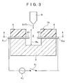
- Fig. 3 is a sectional view along arrows of line I-I of Fig. 2.
- the opposed electrodes E 11 , E 21 are provided in close contact with the substrate 3 formed of a glass, synthetic resin or the like.
- an inorganic material such as SiO 2 or a synthetic resin layer 4 of a polyimide resin or the like as shown in the figure.
- the reaction region 2 can be observed as a recessed portion opened to the upper side, as shown in Fig. 3.
- a detection substance D such as a DNA probe and a target substance T showing an interaction with the detection substance D is dropped from a nozzle N or the like disposed on the upper side, as shown schematically in the figure.
- Fig. 4 is a plan view of the opposed electrodes E 11 , E 21 as viewed along arrows of line II-II of Fig. 3.
- the width (or thickness) W 1 of the projected electrode portions e1, e2 may be set to, for example, about 0.5 ⁇ m, and the interval W 2 between the projected electrode portions e1 and e1 (or e2 and e2) may be set to, for example, about 1 to 10 ⁇ m.
- the length W 3 of the projected electrode portions e1, e2 and the depth W 4 (see Fig. 3) of the reaction region 2 may be appropriately determined according to the molecular lengths of the detection substance D and the target substance T to be dealt with.
- Fig. 5 is a plan view showing the form configuration of opposed electrodes E 12 , E 22 in a detecting unit 1c representing another modified embodiment.
- the opposed electrodes E 12 , E 22 have projected electrode portions e11, e21 which are pointed in triangular shape.
- the projected electrode portions may be appropriately formed in any shape that has such an edge shape that the electric lines of force (described later) are easily concentrated thereon.
- a step concerning the interaction detection by use of the detecting unit according to an embodiment of the present invention will be described, taking as a representative example the action at the electrode E 1 of the detecting unit 1a shown in Fig. 1.
- hybridization is taken as the interaction in the step example, the interaction is not limited to the hybridization.
- an aqueous solution containing a DNA probe D 1 as a representative example of the detection substance D is dropped in a predetermined quantity from a nozzle (see Fig. 3) into a reaction region 2.
- a switch S 1 is turned ON, to impress an AC electric field from a power source V 1 .
- the impressed electric field for example, about 1 ⁇ 10 6 V/m and about 1 MHz can be selected preferably (see Masao Washizu and Osamu Kurosawa: "Electrostatic Manipulation of DNA in Microfabricated Structures", IEEE Transaction on Industrial Application, Vol. 26, No. 26, pp.1165-1172 (1990)).
- the DNA probe D 1 at the time of being dropped has a random coil form high-order structure under the action of the Brownian motion.
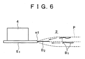
- the DNA probe D 1 in the librated state denoted by symbol D 1 in Fig. 6 is moved by dielectricphoresis toward the projected electrode portion e1 while being stretched along the AC electric field, and, finally, its terminal end portion is fixed to the projected electrode portion e1 where the electric lines of force P are concentrated.
- symbol D 2 in Fig. 6 denotes the fixed DNA probe.
- the system in the case where the surface of the projected electrode portion e1 is surface treated with streptoavidin, the system is suitable for fixation of the terminal end of the viotinated DNA probe.
- the system in the case where the surface of the projected electrode portion e1 is surface treated with a thiol (SH) group, the system is suitable for fixing the DNA probe, modified with the thiol group at the terminal end thereof, by a disulfide bond (-S-S- bond).
- the assembly is washed with a predetermined buffer solution (e.g., phosphate buffered saline), whereby surplus DNA probes and the DNA probes non-specifically adsorbed on the surface of the projected electrode portion e1 can be removed from the reaction region 2.
- a predetermined buffer solution e.g., phosphate buffered saline
- a solution containing a target DNA as a representative example of the target substance T shown in Fig. 3 is dropped into the reaction region 2, and thereafter the switch S 1 shown in Fig. 1 and the like is turned ON, to impress an AC electric field.
- the electric field condition in this case also, for example, about 1 ⁇ 10 6 V/m and about 1 MHz can be preferably selected (see Masao Washizu and Osamu Kurosawa: "Electrostatic Manipulation of DNA in Microfabricated Structures", IEEE Transaction on Industrial Application, Vol. 26, No. 26, pp.1165-1172 (1990)).
- the target DNA denoted by symbol T 1 in Fig. 7 is also moved by dielectricphoresis toward the projected electrode portion e1 while being stretched along the AC electric field, and, finally, it is moved to the vicinity of the projected electrode portion e1 where the electric lines of force P are concentrated.
- an intercalator capable of being selectively inserted and bonded to a double chain portion may be dropped simultaneously.
- Fig. 7 schematically shows the condition where the hybridization has proceeded between the fixed DNA probe D 2 and the target DNA in the stretched state denoted by symbol T 1 .
- the intercalator may be dropped into the reaction region 2 after the hybridization.
- the target DNA denoted by symbol T (T 1 ) is longer than the DNA probe D 2 ; therefore, the target DNAs may interfere with each other in the narrow reaction region 2 to bring about a steric hindrance, which hampers the hybridization, or they may adhere to wall surfaces of the reaction region 2 in the vicinity of the fixation surface. Thus, the progress of the hybridization may often be inhibited.
- the projected electrode portions e1 and e2 forming a nonuniform electric field have electrode edges present at positions far from the surrounding wall surfaces, and the projected electrode portions can be spaced from each other (see Figs. 4 and 5). Therefore, there is secured a sufficient space for hybridization, so that a steric hindrance is generated with difficulty.
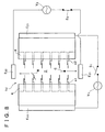
- a switch S 2 shown in Fig. 8 is turned ON, to impress an AC electric field on the opposed electrodes E 21 -E 22 from a power source V 2 , whereby the mishybridized DNA (denoted by symbol M) and the surplus intercalator C can be drawn to the opposed electrode E 21 or E 22 and removed from the detection portion.
- the detecting unit will be described by taking an embodiment denoted by symbol 1b as a representative example.
- predetermined electrode layers E, E are formed on the glass substrate 3 by use of gold (see Fig. 9).
- a photosensitive resin layer e.g., a polyimide resin layer
- the electrode layers E, E to secure the depth required of a reaction region 2.
- the substrate 3 is etched by dry etching technique such as RIE.
- the etching of the glass-made substrate 3 may be carried out at a stroke by soft etching using the HF solution, without adopting the above-mentioned dry etching technique.
- a bioassay substrate such as DNA chip can be provided with which interactions such as hybridization can be made to proceed in a short time and collective analysis can be performed.
- Fig. 13 is a diagram showing one example of the bioassay substrate. As shown in Fig. 13, for example, a multiplicity of detecting units 1a and the like can be arranged on a disk-like substrate 5 in such a manner that they can be divided into groups.
- the detection of the interaction proceeding at any detecting unit 1a or the like provided on the substrate 5 can be carried out by use of a known optical detection means by which a fluorescent substance preliminarily marked onto the detection substance D fixed to the electrode surface or a fluorescent intercalator inserted and bonded to a substance (double chain nucleic acid) showing an interaction is irradiated with fluorescence exciting rays at a predetermined wavelength and the fluorescence is detected.
- a method may be adopted in which the light-emitting image of the detecting unit 1a and the like is picked up, and the quantity of light obtained from the image is quantitatively analyzed and detected.
- a unit for detecting an interaction between substances, a bioassay substrate including the detecting unit, and a preferable method of manufacturing the detecting unit are provided.
- the detecting unit includes: a reaction region for providing sites for the interaction, such as hybridization, between the substances; and opposed electrodes disposed oppositely to each other so as to make it possible to impress an electric field on a medium, such as an aqueous solution and a gel, contained in the reaction region, wherein each of electrodes constituting the opposed electrodes have projected electrode portions projected toward the reaction region.
Landscapes
- Engineering & Computer Science (AREA)
- Microelectronics & Electronic Packaging (AREA)
- Apparatus Associated With Microorganisms And Enzymes (AREA)
- Investigating Or Analysing Biological Materials (AREA)
- Investigating Or Analysing Materials By The Use Of Chemical Reactions (AREA)
- Measuring Or Testing Involving Enzymes Or Micro-Organisms (AREA)
Abstract
Description
- The present invention relates to detecting interaction between substances. Embodiments of the present invention relate to a technology of arranging opposed electrodes in a reaction region for providing sites for an interaction between substances, and applying a predetermined electric field, to thereby perform a control of the high-order structures of the substances, movements of the substances, fixation of the substances, removal of unnecessary substances, etc.
- A principal background art relating to embodiments of the present invention will be described. First, a first background art (related art) is a technology concerning a bioassay integrated substrate so-called DNA chips or DNA microarrays (hereinafter referred to generically "DNA chips") in which predetermined DNAs are finely arranged by the microarray technique (see, for example, Japanese Patent Laid-open No. Hei 4-505763, and W098/503841).
- The DNA chip technology uses a structure in which a multiplicity of kinds of and a multiplicity of DNA oligo-chains, cDNAs (complementary DNAs) and the like are integrated on a glass substrate or a silicon substrate, and is characterized in that it is possible to perform collective analysis of intermolecular interactions such as hybridization. Therefore, DNA chips have been utilized for analysis of variations in genes, SNPs (single nucleotide polymorphisms) analysis, gene expression frequency analysis, etc. and has come to be utilized widely in drug development, clinical diagnosis, pharmacological genomics, forensic medicine and other fields. Other than the DNA chips, there have also been developed protein chips including proteins on a substrate, biosensor chips for analyzing interactions between various substances, and the like.
- A second background art is a technology concerning actions of an electric field on substances present in an electrically charged state in a liquid phase. Specifically, it is known that a nucleotide chain (nucleic acid molecule) is stretched or moved under the action of an electric field in a liquid phase. The principle of this phenomenon is considered as follows. Phosphate ions (negative charges) constituting the skeleton of the nucleotide chain and hydrogen atoms (positive charges) formed by ionization of water present in the surroundings of the phosphate ions are considered to be forming ionic fogs, the polarization vectors (dipoles) generated by the negative charges and the positive charges are as a whole aligned in one direction upon application of a high-frequency high voltage, with the result of extension of the nucleotide chain, and, in addition, when a nonuniform electric field with electric lines of force concentrated on a portion is impressed, the nucleotide chain is moved toward the portion on which the electric lines of force are concentrated (see Seiichi Suzuki, Takeshi Yamanashi, Shin-ichi Tazawa, Osamu Kurosawa and Masao Washizu: "Quantitative analysis on electrostatic orientation of DNA in stationary AC electric field using fluorescence anisotropy", IEEE Transaction on Industrial Applications, Vol. 34, No. 1, pp.75-83 (1998)). Besides, it is known that when a DNA solution is placed in fine electrodes having a gap of several tens to several hundreds of micrometers and a high-frequency electric field of about 1 MV/m and 1 MHz is applied thereto, dielectric polarization occurs in the DNA present in a random coil form, resulting in that the DNA molecule is stretched in a straight line form in parallel to the electric field. Then, by this electrodynamic effect called "dielectricphoresis", the polarized DNA is spontaneously drawn to the electrode end, and is fixed in the form of having one end in contact with the electrode edge (see Masao Washizu, "DNA handling conducted while viewing", Visualized Information, Vol. 20, No. 76 (January, 2000)).
- The above-mentioned DNA chip technology is a technology in which a reaction region for providing sites for an interaction between substances in a medium is preliminarily set on a substrate, and a detection nucleotide chain such as a probe DNA is preliminarily fixed in the reaction region, to thereby analyze the hybridization which is an interaction between the detection nucleotide chain and a complementary target nucleotide chain.
- In the DNA chip technology, however, there have been the problems that: (1) the fixed detection nucleotide chain shows a high-order structure in which it is entangled or rounded in a random coil form under the action of Brownian motion; (2) an interference (e.g., adhesion or contact) between the fixed detection nucleotide chain and the surrounding surfaces occurs; (3) there is a deviation in the integration density of the detection nucleotide chains on the fixation surface: and (4) non-complementary nucleotide chains and surplus intercalators are present in the vicinity of the fixed detection nucleotide chain.
- Hitherto, it has been impossible to solve these problems. At the time of hybridization, therefore, a steric hindrance due to the high-order structured or non-complementary nucleotide chains occurs. Accordingly, the DNA chip technology has had the technical problems that the hybridization efficiency is poor, a long time is taken to achieve the reaction, and pseudo-positivity and pseudo-negativity are generated, with the result of a lowering in detection accuracy.
- Accordingly, embodiments of the present invention seek to provide a detecting unit with which it is possible to freely perform a control of high-order structures of substance, movement of the substances, fixation of the substances, removal of unnecessary substances, etc., and a bioassay substrate provided with the detecting unit.
- According to an aspect of the present invention, there is provided a unit for detecting an interaction between substances including:
- a reaction region for providing sites for the interaction between the substances; and
- opposed electrodes disposed oppositely so as to make it possible to apply an electric field to a medium contained in the reaction region; wherein each of electrodes constituting the opposed electrodes is in the form of being projected toward the reaction region.
-
- According to another aspect of the present invention, there is provided a bioassay substrate which includes an interaction detecting unit having:
- a reaction region for providing sites for the interaction between the substances; and
- opposed electrodes disposed oppositely so as to make it possible to apply an electric field to a medium contained in the reaction region; wherein each of electrodes constituting the opposed electrodes is in the form of being projected toward the reaction region.
-
- According to still another aspect of the present invention, there is provided a method of manufacturing an interaction detecting unit including the steps of:
- forming an electrode layer composed of a predetermined projected electrode pattern on a substrate;
- laminating a photosensitive resin layer on the electrode layer;
- conducting dry etching with the resin layer and the electrode layer as masks; and
- conducting wet etching on the lower side of the projected electrode portion to form projected electrodes.
-
- According to embodiments of the present invention, the high-order structure of a detection nucleotide such as DNA probe or a target nucleotide chain can be put from a random coil form into a stretched state under the action of an electric field applied, so that it is possible to obviate steric hindrances at the time of the interaction such as hybridization. By the action of the electric field, it is possible to align and fix the detection substance on the electrode surfaces, and to enhance the concentrations of the detection substance and the target substances on the surfaces. By these effects, the efficiency and accuracy of the interaction are enhanced, so that the operation time can be shortened, and, since the generation of pseudo-positivity or pseudo-negativity is restrained, the detection accuracy can be enhanced.
- Embodiments of the present invention promise a high efficiency of the interaction such as hybridization at the detecting unit, so that it is possible to largely shorten the time required for the interaction. Besides, since it is possible to form an environment promising an easy progress of the interaction with high accuracy, it is possible to suppress the generation of pseudo-positivity or pseudo-negativity.
- Therefore, embodiments of the present invention can be utilized for a bioassay substrate such as DNA chip which has such characteristics that the efficiency of the assay operation for interaction detection is excellent and that the detection accuracy is high.
- Further particular and preferred aspects of the present invention are set out in the accompanying independent and dependent claims. Features of the dependent claims may be combined with features of the independent claims as appropriate, and in combinations other than those explicitly set out in the claims.
- The present invention will be described further, by way of example only, with reference to preferred embodiments thereof as illustrated in the accompanying drawings, in which:
- Fig. 1 is a top plan view schematically showing the concept of the basic configuration of a unit for detecting an interaction between substances according to an embodiment of the present invention;
- Fig. 2 is a top plan view schematically showing the configuration of a modified form of the detecting unit according to an embodiment of the present invention;
- Fig. 3 is a sectional view along arrows of line I-I of Fig. 2;
- Fig. 4 is a plan view of opposed electrodes viewed along arrows of line II-II of Fig. 3;
- Fig. 5 is a plan view showing the form configuration of opposed electrodes in a detecting unit of a modified form;
- Fig. 6 is a diagram for illustrating an example of a step concerning the interaction detection by use of the detecting unit according to an embodiment of the present invention (a diagram showing the manner of a DNA probe fixation step);
- Fig. 7 is a diagram for illustrating an example of a step concerning the interaction detection by use of the detecting unit according to an embodiment of the present invention (a diagram showing the manner of a target DNA stretching and drawing step);
- Fig. 8 is a diagram showing the configuration of a detecting unit provided with intersecting electrodes;
- Fig. 9 is a diagram for illustrating an example of a method of manufacturing the detecting unit according to an embodiment of the present invention (stage of laminating an electrode layer);
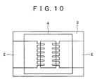
- Fig. 10 is a diagram for illustrating the example of the method of manufacturing the detecting unit according to an embodiment of the present invention (stage of laminating a resin layer);
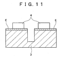
- Fig. 11 is a diagram for illustrating the example of the method of manufacturing the detecting unit according to an embodiment of the present invention (dry etching stage);
- Fig. 12 is a diagram for illustrating the example of the method of manufacturing the detecting unit according to an embodiment of the present invention (soft etching stage); and
- Fig. 13 is a diagram showing an example of a disk form substrate provided thereon with detecting units according to an embodiment of the present invention.
-
- First, principal technical terms used in embodiments of the present invention will be defined. The term "interaction" used in embodiments of the present invention widely means chemical bondings inclusive of non-covalent bonding, covalent bonding, and hydrogen bonding and dissociation between substances, and includes hybridization which is a complementary bonding between nucleic acids (nucleotide chains), for example.
- Next, the term "opposed electrodes" means at least one pair of electrodes which are arranged oppositely to each other.
- The term "nucleotide chain" means a polymer of a phosphoric acid ester of a nucleoside in which a purine or pyrimidine base and a sugar are bonded by glycoside bonding, and widely includes oligonucleotides inclusive of probe DNAs, polynucleotides, DNAs (whole length or sections thereof) formed by polymerization of purine nucleotide with pyrimidine nucleotide, cDNAs (c probe DNAs) obtained by reverse transcription, RNAs, polyamide nucleotide derivatives (PNAs), etc.
- The term "hybridization" means a complementary chain (double chain) forming reaction between nucleotide chains having complementary base sequence structures. The term "mishybridization" means the complementary chain forming reaction which is not normal.
- The term "reaction region" means a region which can provide reaction sites for hybridization or other interactions, and examples thereof include a reaction site in the shape of a well capable of preserving or holding a medium such as a liquid phase and a gel. The interaction conducted in the reaction region is not narrowly limited, provided that the interaction conforms to the object or effects of the present invention. Examples of the interaction include not only an interaction between a single-chain nucleic acids, i.e., hybridization but also an interaction between peptide (or protein) and a desired double-chain nucleic acid formed from a detection nucleic acid, an enzyme response reaction and other intermolecular interactions. Where the double-chain nucleic acid is used, for example, the bonding between a receptor molecule of a hormone receptor or the like which is a transcription factor and a response sequence DNA portion, and the like can be analyzed.
- The term "detection substance" is a substance which is preliminarily added into the reaction region and which is present in a free state in the region, or a substance which is present in the state of being fixed to a predetermined surface portion of the reaction region. The detection substance is a substance for capturing and detecting a substance showing a specific interaction with the substance, and includes detection nucleotide chains such as DNA probes.
- The term "target substance" means a substance which serves as a target of an interaction with the detection substance, and examples thereof include a nucleotide chain having a base sequence complementary to the DNA probe.
- The term "steric hindrance" means a phenomenon in which due to the presence of a bulky substituent group in the vicinity of a reaction center or the like in a molecule, the posture of a reaction molecule, or the steric structure (high-order structure), the access of molecules of the medium species becomes difficult and, as a result, it becomes difficult for the desired reaction (hybridization, in the present patent application) to take place.
- The term "dielectricphoresis" is a phenomenon in which molecules are driven toward the higher electric field side in a field where the electric field is anisotropic. Further, where an AC voltage is applied, the polarity of polarization is reversed attendant on the reversion of the polarity of the applied voltage, so that the driving effect can be obtained in the same manner as in the case of DC (see "Micromachines and Material Technology (published by CMC Publishing Co., Ltd.)" complied under the supervision of Teru Hayashi, pp.37-46,
Chapter 5, Cell and DNA manipulation). - The term "bioassay substrate" means an information integration substrate used for the purpose of biochemical or molecular biological analysis, and includes the so-called DNA chip.
- Now, a preferred embodiment of the present invention will be described below referring to the accompanying drawings. First, Fig. 1 is a top plan view schematically showing the concept of the basic configuration of a unit for detecting an interaction between substances (hereinafter referred to simply as "detecting unit") according to an embodiment of the present invention.
-
Symbol 1a in Fig. 1 denotes an essential part of the most basic embodiment of the detecting unit. The detectingunit 1a is formed on a substrate (seesymbol 3 in Fig. 3 and the like) formed, for example, of a glass, synthetic resin or the like, and is a portion devised for detecting an interaction between substances. - The detecting
unit 1a and other detectingunits 1b (Fig. 2), 1c (Fig. 5), and 1d (Fig. 8) are each provided with areaction region 2 having a predetermined volume capable of preserving or holding a medium such as an aqueous solution and a gel which serves as sites for the interaction between the substances, and a pair of opposed electrodes E1, E2 disposed oppositely to each other on both sides of thereaction region 2. - The opposed electrodes E1, E2 can be formed of a metal such as gold and aluminum or of a conductor other than metal; for example, they can be formed of a transparent conductor such as ITO (Indium Tin Oxide). Incidentally, the opposed electrodes E1, E2 are connected to a power source V1 shown, by turning ON a switch S1.
- The opposed electrodes E1, E2 are each formed in the shape of being projected toward the
reaction region 2, and include projected electrode portions e1, e2 in a needle-like or rod-like form which are opposed to each other. - Of the opposed electrodes E1, E2, each surface on the side for fronting the
reaction region 2 is covered with an insulation layer (not shown). The insulation layer plays the role of preventing an electrochemical reaction due to an ionic solution which may be preserved in thereaction region 2. The insulation layer can be formed of such a material as SiO2, SiN, SiOC, SiOF, SiC, TiO2, etc. - Fig. 2 is a top plan view schematically showing the configuration of a modified form of the detecting unit according to an embodiment of the present invention. The detecting
unit 1b representing a modified form includes opposed electrodes E11, E21 having a configuration in which the above-mentioned opposed electrodes E1, E2 are respectively arrayed at a predetermined regular interval. Therefore, a plurality of pairs (six pairs in the figure) of projected electrode portions e1, e2 are disposed oppositely to each other in thereaction region 2 of the detectingunit 1b. - Incidentally, though not shown in the figure, the projected electrode portions e1 constituting the electrode E11 and the projected electrode portions e2 constituting the electrode E21 may not necessarily be arrayed at the regular interval, and the interval can be appropriately selected. Besides, there can be adopted a configuration in which the number of the projected electrode portions on one side is greater than the number of the projected electrode portions on the other side, or a configuration in which the number density per unit length of the projected electrode portions on one side is higher than the number density per unit length of the projected electrode portions on the other side. It is considered that the electric lines of force are concentrated more on the side of the projected electrode portions with a higher number density.
- Next, Fig. 3 is a sectional view along arrows of line I-I of Fig. 2. As shown in Fig. 3, the opposed electrodes E11, E21 are provided in close contact with the
substrate 3 formed of a glass, synthetic resin or the like. On the opposed electrodes E11, E21 is formed an inorganic material such as SiO2 or asynthetic resin layer 4 of a polyimide resin or the like as shown in the figure. - The
reaction region 2 can be observed as a recessed portion opened to the upper side, as shown in Fig. 3. Into thereaction region 2, an aqueous solution or the like containing a detection substance D such as a DNA probe and a target substance T showing an interaction with the detection substance D is dropped from a nozzle N or the like disposed on the upper side, as shown schematically in the figure. - Fig. 4 is a plan view of the opposed electrodes E11, E21 as viewed along arrows of line II-II of Fig. 3. The width (or thickness) W1 of the projected electrode portions e1, e2 may be set to, for example, about 0.5 µm, and the interval W2 between the projected electrode portions e1 and e1 (or e2 and e2) may be set to, for example, about 1 to 10 µm. In addition to W1 and W2, the length W3 of the projected electrode portions e1, e2 and the depth W4 (see Fig. 3) of the
reaction region 2 may be appropriately determined according to the molecular lengths of the detection substance D and the target substance T to be dealt with. - Fig. 5 is a plan view showing the form configuration of opposed electrodes E12, E22 in a detecting unit 1c representing another modified embodiment. The opposed electrodes E12, E22 have projected electrode portions e11, e21 which are pointed in triangular shape. Thus, the projected electrode portions may be appropriately formed in any shape that has such an edge shape that the electric lines of force (described later) are easily concentrated thereon.
- Now, referring to Figs. 6 and 7, an example of a step concerning the interaction detection by use of the detecting unit according to an embodiment of the present invention will be described, taking as a representative example the action at the electrode E1 of the detecting
unit 1a shown in Fig. 1. Incidentally, while hybridization is taken as the interaction in the step example, the interaction is not limited to the hybridization. - First, an aqueous solution containing a DNA probe D1 as a representative example of the detection substance D is dropped in a predetermined quantity from a nozzle (see Fig. 3) into a
reaction region 2. Next, a switch S1 is turned ON, to impress an AC electric field from a power source V1. As a preferable condition of the impressed electric field here, for example, about 1 × 10⁶ V/m and about 1 MHz can be selected preferably (see Masao Washizu and Osamu Kurosawa: "Electrostatic Manipulation of DNA in Microfabricated Structures", IEEE Transaction on Industrial Application, Vol. 26, No. 26, pp.1165-1172 (1990)). Incidentally, the DNA probe D1 at the time of being dropped has a random coil form high-order structure under the action of the Brownian motion. - By the application of the electric field, the DNA probe D1 in the librated state denoted by symbol D1 in Fig. 6 is moved by dielectricphoresis toward the projected electrode portion e1 while being stretched along the AC electric field, and, finally, its terminal end portion is fixed to the projected electrode portion e1 where the electric lines of force P are concentrated. Incidentally, symbol D2 in Fig. 6 denotes the fixed DNA probe.
- Incidentally, in the case where the surface of the projected electrode portion e1 is surface treated with streptoavidin, the system is suitable for fixation of the terminal end of the viotinated DNA probe. Alternatively, in the case where the surface of the projected electrode portion e1 is surface treated with a thiol (SH) group, the system is suitable for fixing the DNA probe, modified with the thiol group at the terminal end thereof, by a disulfide bond (-S-S- bond).
- After the fixation of the DNA probe D1 by the above-mentioned method is finished, the assembly is washed with a predetermined buffer solution (e.g., phosphate buffered saline), whereby surplus DNA probes and the DNA probes non-specifically adsorbed on the surface of the projected electrode portion e1 can be removed from the
reaction region 2. - Subsequently, a solution containing a target DNA as a representative example of the target substance T shown in Fig. 3 is dropped into the
reaction region 2, and thereafter the switch S1 shown in Fig. 1 and the like is turned ON, to impress an AC electric field. As the electric field condition in this case, also, for example, about 1×10⁶ V/m and about 1 MHz can be preferably selected (see Masao Washizu and Osamu Kurosawa: "Electrostatic Manipulation of DNA in Microfabricated Structures", IEEE Transaction on Industrial Application, Vol. 26, No. 26, pp.1165-1172 (1990)). - Upon the application of the electric field, the target DNA denoted by symbol T1 in Fig. 7 is also moved by dielectricphoresis toward the projected electrode portion e1 while being stretched along the AC electric field, and, finally, it is moved to the vicinity of the projected electrode portion e1 where the electric lines of force P are concentrated. Incidentally, at the time of dropping the target DNA-containing solution into the
reaction region 2, an intercalator capable of being selectively inserted and bonded to a double chain portion may be dropped simultaneously. - Next, the switch S1 is turned OFF (see Fig. 1), to stop the application of the AC electric field, and the hybridization is made to proceed under the natural Brownian motion. Fig. 7 schematically shows the condition where the hybridization has proceeded between the fixed DNA probe D2 and the target DNA in the stretched state denoted by symbol T1. Incidentally, the intercalator may be dropped into the
reaction region 2 after the hybridization. - Generally, the target DNA denoted by symbol T (T1) is longer than the DNA probe D2; therefore, the target DNAs may interfere with each other in the
narrow reaction region 2 to bring about a steric hindrance, which hampers the hybridization, or they may adhere to wall surfaces of thereaction region 2 in the vicinity of the fixation surface. Thus, the progress of the hybridization may often be inhibited. - In embodiments of the present invention, on the other hand, the projected electrode portions e1 and e2 forming a nonuniform electric field have electrode edges present at positions far from the surrounding wall surfaces, and the projected electrode portions can be spaced from each other (see Figs. 4 and 5). Therefore, there is secured a sufficient space for hybridization, so that a steric hindrance is generated with difficulty.
- Incidentally, as shown in the modified embodiment in Fig. 8, there may be disposed another pair of opposed electrodes E21-E22 having an opposition axis intersecting (shown in the figure) vertically or horizontally to the opposed electrodes E11-E21. After the hybridization, a switch S2 shown in Fig. 8 is turned ON, to impress an AC electric field on the opposed electrodes E21-E22 from a power source V2, whereby the mishybridized DNA (denoted by symbol M) and the surplus intercalator C can be drawn to the opposed electrode E21 or E22 and removed from the detection portion.
- Next, based on Figs. 9 to 12, one example of the method of manufacturing the detecting unit according to an embodiment of the present invention will be described. The detecting unit will be described by taking an embodiment denoted by
symbol 1b as a representative example. Taking as an example the case where asubstrate 3 is made of a glass, predetermined electrode layers E, E are formed on theglass substrate 3 by use of gold (see Fig. 9). In this case, for securing close contact between theglass substrate 3 and the gold-made electrode layers E, E, it is desirable to preliminarily provide a layer (not shown) of Cr, Ti or the like between theglass substrate 3 and the electrode layers E, E. - Next, as shown in Fig. 10, for example, a photosensitive resin layer (e.g., a polyimide resin layer) 4 is laminated on the electrode layers E, E, to secure the depth required of a
reaction region 2. Subsequently, as shown in Fig. 11, with theresin layer 4 and the electrode layers E, E as masks, thesubstrate 3 is etched by dry etching technique such as RIE. - Thereafter, by use of an HF solution or the like, the lower side of projected electrode portions is wet etched, to form projected electrode portions E11, E21. Incidentally, since gold is not damaged by the HF solution, a projected electrode structure as shown in Fig. 12 can finally be formed.
- Incidentally, the etching of the glass-made
substrate 3 may be carried out at a stroke by soft etching using the HF solution, without adopting the above-mentioned dry etching technique. In the fabrication of the detecting unit according to the present invention, however, it is desirable to jointly use the dry etching and the soft etching, for enhancing controllability of the electrode shape. Besides, in the case of covering the thus formed projected electrode portions with an insulation layer, it is desirable to form a film of SiO2 or the like by CVD, for example. - By preliminarily arranging the detecting units denoted by
symbols 1a to 1d above-mentioned in a predetermined array on the substrate, a bioassay substrate such as DNA chip can be provided with which interactions such as hybridization can be made to proceed in a short time and collective analysis can be performed. - Fig. 13 is a diagram showing one example of the bioassay substrate. As shown in Fig. 13, for example, a multiplicity of detecting
units 1a and the like can be arranged on a disk-like substrate 5 in such a manner that they can be divided into groups. - Incidentally, the detection of the interaction proceeding at any detecting
unit 1a or the like provided on thesubstrate 5 can be carried out by use of a known optical detection means by which a fluorescent substance preliminarily marked onto the detection substance D fixed to the electrode surface or a fluorescent intercalator inserted and bonded to a substance (double chain nucleic acid) showing an interaction is irradiated with fluorescence exciting rays at a predetermined wavelength and the fluorescence is detected. Alternatively, a method may be adopted in which the light-emitting image of the detectingunit 1a and the like is picked up, and the quantity of light obtained from the image is quantitatively analyzed and detected. - A unit for detecting an interaction between substances, a bioassay substrate including the detecting unit, and a preferable method of manufacturing the detecting unit are provided. The detecting unit includes: a reaction region for providing sites for the interaction, such as hybridization, between the substances; and opposed electrodes disposed oppositely to each other so as to make it possible to impress an electric field on a medium, such as an aqueous solution and a gel, contained in the reaction region, wherein each of electrodes constituting the opposed electrodes have projected electrode portions projected toward the reaction region.
- Although particular embodiments have been described herein, it will be appreciated that the invention is not limited thereto and that many modifications and additions thereto may be made within the scope of the invention. For example, various combinations of the features of the following dependent claims can be made with the features of the independent claims without departing from the scope of the present invention.
Claims (7)
- A unit for detecting an interaction between substances comprising:wherein each of electrodes constituting said opposed electrodes is in the form of being projected toward said reaction region.a reaction region for providing sites for said interaction between said substances; andopposed electrodes disposed oppositely so as to make it possible to apply an electric field to a medium contained in said reaction region;
- The unit for detecting an interaction between substances as set forth in claim 1, wherein said opposed electrodes are arrayed at a predetermined interval.
- The unit for detecting an interaction between substances as set forth in claim 1, wherein an alternating current field is applied to said opposed electrodes.
- The unit for detecting an interaction between substances as set forth in claim 3, wherein tip end portions of said opposed electrodes serve as portions for fixing a nucleotide chain for detection.
- The unit for detecting an interaction between substances as set forth in claim 1, wherein said interaction is hybridization.
- A bioassay substrate which comprises an interaction detecting unit including:wherein each of electrodes constituting said opposed electrodes is in the form of being projected toward said reaction region.a reaction region for providing sites for said interaction between said substances; andopposed electrodes disposed oppositely so as to make it possible to apply an electric field to a medium contained in said reaction region;
- A method of manufacturing an interaction detecting unit comprising the steps of:forming an electrode layer composed of a predetermined projected electrode pattern on a substrate;laminating a photosensitive resin layer on said electrode layer;conducting dry etching with said resin layer and said electrode layer as masks; andconducting wet etching on the lower side of said projected electrode portion to form projected electrodes.
Applications Claiming Priority (2)
| Application Number | Priority Date | Filing Date | Title |
|---|---|---|---|
| JP2003343955A JP4328167B2 (en) | 2003-10-02 | 2003-10-02 | A part for detecting an interaction between substances using a protruding counter electrode and a substrate for bioassay provided with the part |
| JP2003343955 | 2003-10-02 |
Publications (1)
| Publication Number | Publication Date |
|---|---|
| EP1520628A1 true EP1520628A1 (en) | 2005-04-06 |
Family
ID=34309128
Family Applications (1)
| Application Number | Title | Priority Date | Filing Date |
|---|---|---|---|
| EP04256025A Withdrawn EP1520628A1 (en) | 2003-10-02 | 2004-09-30 | Detecting interaction between substances |
Country Status (4)
| Country | Link |
|---|---|
| US (1) | US20050112646A1 (en) |
| EP (1) | EP1520628A1 (en) |
| JP (1) | JP4328167B2 (en) |
| CN (1) | CN1661105A (en) |
Families Citing this family (4)
| Publication number | Priority date | Publication date | Assignee | Title |
|---|---|---|---|---|
| US20060275779A1 (en) * | 2005-06-03 | 2006-12-07 | Zhiyong Li | Method and apparatus for molecular analysis using nanowires |
| JP4779468B2 (en) * | 2005-07-01 | 2011-09-28 | ソニー株式会社 | Interaction detecting unit, bioassay substrate, and method related thereto |
| JP4748451B2 (en) * | 2006-02-08 | 2011-08-17 | 凸版印刷株式会社 | Hybridization detection method |
| JP5222599B2 (en) * | 2007-07-20 | 2013-06-26 | 株式会社日立ハイテクノロジーズ | Nucleic acid analysis device and nucleic acid analysis apparatus using the same |
Citations (3)
| Publication number | Priority date | Publication date | Assignee | Title |
|---|---|---|---|---|
| JPH05283970A (en) * | 1992-03-31 | 1993-10-29 | Hitachi Ltd | High frequency band surface acoustic wave element |
| WO2001005511A1 (en) * | 1999-07-20 | 2001-01-25 | University Of Wales, Bangor | Electrodes for generating and analysing dielectrophoresis |
| WO2003048389A2 (en) * | 2001-12-07 | 2003-06-12 | Brunel University | Test apparatus |
Family Cites Families (4)
| Publication number | Priority date | Publication date | Assignee | Title |
|---|---|---|---|---|
| US4707422A (en) * | 1983-06-27 | 1987-11-17 | Voltaix, Inc. | Composite coating for electrochemical electrode and method |
| US5106468A (en) * | 1985-12-30 | 1992-04-21 | Exxon Research And Engineering Company | Electrophoretic separation |
| US6034396A (en) * | 1998-01-28 | 2000-03-07 | Texas Instruments - Acer Incorporated | Ultra-short channel recessed gate MOSFET with a buried contact |
| US6218175B1 (en) * | 1998-10-30 | 2001-04-17 | International Business Machines Corporation | Nano-devices using block-copolymers |
-
2003
- 2003-10-02 JP JP2003343955A patent/JP4328167B2/en not_active Expired - Fee Related
-
2004
- 2004-09-30 CN CN2004100951662A patent/CN1661105A/en active Pending
- 2004-09-30 EP EP04256025A patent/EP1520628A1/en not_active Withdrawn
- 2004-09-30 US US10/955,378 patent/US20050112646A1/en not_active Abandoned
Patent Citations (3)
| Publication number | Priority date | Publication date | Assignee | Title |
|---|---|---|---|---|
| JPH05283970A (en) * | 1992-03-31 | 1993-10-29 | Hitachi Ltd | High frequency band surface acoustic wave element |
| WO2001005511A1 (en) * | 1999-07-20 | 2001-01-25 | University Of Wales, Bangor | Electrodes for generating and analysing dielectrophoresis |
| WO2003048389A2 (en) * | 2001-12-07 | 2003-06-12 | Brunel University | Test apparatus |
Non-Patent Citations (1)
| Title |
|---|
| PATENT ABSTRACTS OF JAPAN vol. 018, no. 069 (E - 1502) 4 February 1994 (1994-02-04) * |
Also Published As
| Publication number | Publication date |
|---|---|
| CN1661105A (en) | 2005-08-31 |
| JP4328167B2 (en) | 2009-09-09 |
| JP2005106757A (en) | 2005-04-21 |
| US20050112646A1 (en) | 2005-05-26 |
Similar Documents
| Publication | Publication Date | Title |
|---|---|---|
| US20050112548A1 (en) | Unit for detecting interaction between substances utilizing capillarity, and method and bioassay substrate using the detecting unit | |
| EP1605063B1 (en) | Hybridization detecting unit and DNA chip including the detecting unit | |
| CN102879453B (en) | Method and the device of the charged particle in handling liquids is come based on electrophoresis | |
| JP4645110B2 (en) | Hybridization detection unit using dielectrophoresis, sensor chip including the detection unit, and hybridization detection method | |
| JP4321854B2 (en) | Hybridization and other interaction detection units and DNA chips and other bioassay substrates provided with the detection units | |
| EP1677110A1 (en) | Method for producing bioassay substrate by superposing two substrates one on another and bioassay substrate | |
| US20050112646A1 (en) | Unit for detecting interaction between substances utilizing projected opposed electrodes, and bioassay substrate provided with the detecting unit | |
| KR20080016825A (en) | Interaction detection unit having an electrode of the same potential, a sensor chip using the detection unit, and the interaction detection device | |
| JP2005345353A (en) | Bioassay substrate having a light-blocking layer for fluorescence excitation light | |
| JP4411931B2 (en) | Method for detecting interaction between substances | |
| JP4281479B2 (en) | Bioassay substrate for detecting an interaction between an electrode unit and a substance using the electrode unit | |
| JP4631543B2 (en) | Substance-interaction detection unit, sensor chip using the detection unit, and bioassay method using an electric field | |
| JP4403376B2 (en) | Detecting interaction between substances, bioassay substrate provided with the detection unit, and method for supplying aqueous solution to the detection unit | |
| JP2005351686A (en) | Detection part for interaction between substances using electric field gradient and substrate for bioassay equipped with same detection part for interaction | |
| JP4618007B2 (en) | Bioassay substrate and interaction detector for interaction between substances | |
| WO2008020364A2 (en) | Biochemical sensor device | |
| JP4779468B2 (en) | Interaction detecting unit, bioassay substrate, and method related thereto |
Legal Events
| Date | Code | Title | Description |
|---|---|---|---|
| PUAI | Public reference made under article 153(3) epc to a published international application that has entered the european phase |
Free format text: ORIGINAL CODE: 0009012 |
|
| AK | Designated contracting states |
Kind code of ref document: A1 Designated state(s): AT BE BG CH CY CZ DE DK EE ES FI FR GB GR HU IE IT LI LU MC NL PL PT RO SE SI SK TR |
|
| AX | Request for extension of the european patent |
Extension state: AL HR LT LV MK |
|
| 17P | Request for examination filed |
Effective date: 20050919 |
|
| AKX | Designation fees paid |
Designated state(s): DE FR GB |
|
| RAP1 | Party data changed (applicant data changed or rights of an application transferred) |
Owner name: SONY DEUTSCHLAND GMBH Owner name: SONY CORPORATION |
|
| RAP1 | Party data changed (applicant data changed or rights of an application transferred) |
Owner name: SONY DEUTSCHLAND GMBH Owner name: SONY CORPORATION |
|
| STAA | Information on the status of an ep patent application or granted ep patent |
Free format text: STATUS: THE APPLICATION IS DEEMED TO BE WITHDRAWN |
|
| 18D | Application deemed to be withdrawn |
Effective date: 20110401 |