EP1520529A1 - Unfolding anastomosis ring device - Google Patents
Unfolding anastomosis ring device Download PDFInfo
- Publication number
- EP1520529A1 EP1520529A1 EP04256038A EP04256038A EP1520529A1 EP 1520529 A1 EP1520529 A1 EP 1520529A1 EP 04256038 A EP04256038 A EP 04256038A EP 04256038 A EP04256038 A EP 04256038A EP 1520529 A1 EP1520529 A1 EP 1520529A1
- Authority
- EP
- European Patent Office
- Prior art keywords
- arcuate
- anastomosis
- arcuate members
- ring device
- members
- Prior art date
- Legal status (The legal status is an assumption and is not a legal conclusion. Google has not performed a legal analysis and makes no representation as to the accuracy of the status listed.)
- Granted
Links
- 230000003872 anastomosis Effects 0.000 title claims description 38
- 230000003446 memory effect Effects 0.000 claims description 3
- 229910045601 alloy Inorganic materials 0.000 claims description 2
- 239000000956 alloy Substances 0.000 claims description 2
- 239000003292 glue Substances 0.000 claims description 2
- 229920000642 polymer Polymers 0.000 claims 1
- 230000008901 benefit Effects 0.000 abstract description 5
- 238000002513 implantation Methods 0.000 abstract description 5
- 239000000470 constituent Substances 0.000 abstract 1
- 210000002784 stomach Anatomy 0.000 description 12
- 210000001519 tissue Anatomy 0.000 description 12
- 238000000034 method Methods 0.000 description 11
- 230000033001 locomotion Effects 0.000 description 9
- 230000002496 gastric effect Effects 0.000 description 8
- 208000008589 Obesity Diseases 0.000 description 7
- 238000013459 approach Methods 0.000 description 7
- 208000012696 congenital leptin deficiency Diseases 0.000 description 6
- 208000001022 morbid obesity Diseases 0.000 description 6
- HLXZNVUGXRDIFK-UHFFFAOYSA-N nickel titanium Chemical group [Ti].[Ti].[Ti].[Ti].[Ti].[Ti].[Ti].[Ti].[Ti].[Ti].[Ti].[Ni].[Ni].[Ni].[Ni].[Ni].[Ni].[Ni].[Ni].[Ni].[Ni].[Ni].[Ni].[Ni].[Ni] HLXZNVUGXRDIFK-UHFFFAOYSA-N 0.000 description 6
- 210000000813 small intestine Anatomy 0.000 description 6
- 238000001356 surgical procedure Methods 0.000 description 5
- 239000012530 fluid Substances 0.000 description 4
- 229910001000 nickel titanium Inorganic materials 0.000 description 4
- 238000004519 manufacturing process Methods 0.000 description 3
- 239000000463 material Substances 0.000 description 3
- 210000001953 common bile duct Anatomy 0.000 description 2
- 230000037406 food intake Effects 0.000 description 2
- 235000012631 food intake Nutrition 0.000 description 2
- 239000011521 glass Substances 0.000 description 2
- 238000003780 insertion Methods 0.000 description 2
- 230000037431 insertion Effects 0.000 description 2
- 210000000936 intestine Anatomy 0.000 description 2
- 238000002350 laparotomy Methods 0.000 description 2
- 230000004048 modification Effects 0.000 description 2
- 238000012986 modification Methods 0.000 description 2
- 210000000056 organ Anatomy 0.000 description 2
- 238000002360 preparation method Methods 0.000 description 2
- 230000000717 retained effect Effects 0.000 description 2
- 208000019693 Lung disease Diseases 0.000 description 1
- 206010025476 Malabsorption Diseases 0.000 description 1
- 208000004155 Malabsorption Syndromes Diseases 0.000 description 1
- 206010061902 Pancreatic neoplasm Diseases 0.000 description 1
- 208000006011 Stroke Diseases 0.000 description 1
- 206010052428 Wound Diseases 0.000 description 1
- 208000027418 Wounds and injury Diseases 0.000 description 1
- 239000000853 adhesive Substances 0.000 description 1
- 230000001070 adhesive effect Effects 0.000 description 1
- 230000006399 behavior Effects 0.000 description 1
- 210000000941 bile Anatomy 0.000 description 1
- 230000015572 biosynthetic process Effects 0.000 description 1
- 230000006835 compression Effects 0.000 description 1
- 238000007906 compression Methods 0.000 description 1
- 238000009223 counseling Methods 0.000 description 1
- 230000008878 coupling Effects 0.000 description 1
- 238000010168 coupling process Methods 0.000 description 1
- 238000005859 coupling reaction Methods 0.000 description 1
- 230000007812 deficiency Effects 0.000 description 1
- 230000001419 dependent effect Effects 0.000 description 1
- 206010012601 diabetes mellitus Diseases 0.000 description 1
- 235000005911 diet Nutrition 0.000 description 1
- 230000000378 dietary effect Effects 0.000 description 1
- 210000001198 duodenum Anatomy 0.000 description 1
- 230000000694 effects Effects 0.000 description 1
- 238000012976 endoscopic surgical procedure Methods 0.000 description 1
- 210000001035 gastrointestinal tract Anatomy 0.000 description 1
- 208000019622 heart disease Diseases 0.000 description 1
- 239000007943 implant Substances 0.000 description 1
- 208000015181 infectious disease Diseases 0.000 description 1
- 238000002347 injection Methods 0.000 description 1
- 239000007924 injection Substances 0.000 description 1
- 230000007794 irritation Effects 0.000 description 1
- 238000005304 joining Methods 0.000 description 1
- 238000007629 laparoscopic insertion Methods 0.000 description 1
- 230000007774 longterm Effects 0.000 description 1
- 208000015486 malignant pancreatic neoplasm Diseases 0.000 description 1
- 230000007246 mechanism Effects 0.000 description 1
- 235000020824 obesity Nutrition 0.000 description 1
- 201000002528 pancreatic cancer Diseases 0.000 description 1
- 208000008443 pancreatic carcinoma Diseases 0.000 description 1
- 230000000144 pharmacologic effect Effects 0.000 description 1
- 229920002959 polymer blend Polymers 0.000 description 1
- 230000008569 process Effects 0.000 description 1
- 238000012545 processing Methods 0.000 description 1
- 230000036186 satiety Effects 0.000 description 1
- 235000019627 satiety Nutrition 0.000 description 1
- 239000012781 shape memory material Substances 0.000 description 1
- 239000000243 solution Substances 0.000 description 1
- 210000001562 sternum Anatomy 0.000 description 1
- 238000002560 therapeutic procedure Methods 0.000 description 1
- 230000007704 transition Effects 0.000 description 1
- 238000011282 treatment Methods 0.000 description 1
- 230000002792 vascular Effects 0.000 description 1
- 238000003466 welding Methods 0.000 description 1
Images




Classifications
-
- A—HUMAN NECESSITIES
- A61—MEDICAL OR VETERINARY SCIENCE; HYGIENE
- A61B—DIAGNOSIS; SURGERY; IDENTIFICATION
- A61B17/00—Surgical instruments, devices or methods
- A61B17/11—Surgical instruments, devices or methods for performing anastomosis; Buttons for anastomosis
- A61B17/1114—Surgical instruments, devices or methods for performing anastomosis; Buttons for anastomosis of the digestive tract, e.g. bowels or oesophagus
-
- A—HUMAN NECESSITIES
- A61—MEDICAL OR VETERINARY SCIENCE; HYGIENE
- A61B—DIAGNOSIS; SURGERY; IDENTIFICATION
- A61B17/00—Surgical instruments, devices or methods
- A61B17/064—Surgical staples, i.e. penetrating the tissue
- A61B17/0644—Surgical staples, i.e. penetrating the tissue penetrating the tissue, deformable to closed position
-
- A—HUMAN NECESSITIES
- A61—MEDICAL OR VETERINARY SCIENCE; HYGIENE
- A61B—DIAGNOSIS; SURGERY; IDENTIFICATION
- A61B17/00—Surgical instruments, devices or methods
- A61B2017/00004—(bio)absorbable, (bio)resorbable or resorptive
-
- A—HUMAN NECESSITIES
- A61—MEDICAL OR VETERINARY SCIENCE; HYGIENE
- A61B—DIAGNOSIS; SURGERY; IDENTIFICATION
- A61B17/00—Surgical instruments, devices or methods
- A61B2017/00831—Material properties
- A61B2017/00867—Material properties shape memory effect
-
- A—HUMAN NECESSITIES
- A61—MEDICAL OR VETERINARY SCIENCE; HYGIENE
- A61B—DIAGNOSIS; SURGERY; IDENTIFICATION
- A61B17/00—Surgical instruments, devices or methods
- A61B17/11—Surgical instruments, devices or methods for performing anastomosis; Buttons for anastomosis
- A61B2017/1139—Side-to-side connections, e.g. shunt or X-connections
Definitions
- the present invention relates, in general, to devices and methods for surgically modifying organs and vessels. More particularly, it relates to anastomosis devices for joining two organs such as, for example, two separate lengths of small bowel to each other, a section of small bowel to the stomach, or the common bile duct to the duodenum in a procedure called a choledochoduodenostomy. Vascular anastomosis could be performed as well.
- Creating an anastomosis, or the surgical formation of a passage between two normally distinct vessels, is a critical step of many surgical procedures. This is particularly true of gastric bypass procedures in which two portions of small intestine are joined together and another portion of small intestine is joined to the stomach of the patient. This is also true of surgery to alleviate blockage in the common bile duct by draining bile from the duct to the small intestine during surgery for pancreatic cancer.
- morbid obesity The percentage of the world population suffering from morbid obesity is steadily increasing. Severely obese persons are susceptible to increased risk of heart disease, stroke, diabetes, pulmonary disease, and accidents. Because of the effect of morbid obesity to the life of the patient, methods of treating morbid obesity are being researched.
- Surgical treatments of morbid obesity have been increasingly used with greater success. These approaches may be generalized as those that reduce the effective size of the stomach, limiting the amount of food intake, and those that create malabsorption of the food that it is eaten.
- AGB adjustable gastric bands
- a fluid conduit communicates between an inwardly presented fluid bladder of the AGB to a fluid injection port subcutaneously placed in front of the patient's sternum.
- a syringe needle may then inject or withdraw fluid as desired to adjust the AGB.
- a method for gastric bypass surgery includes the insertion of proximal and distal anastomosis members (e.g., anvils) transorally with grasping forceps.
- the stomach and the small intestine are transected endoscopically by a surgical severing and stapling instrument to create a gastric pouch, a drainage loop, and a Roux limb.
- An endoscopically inserted circular stapler attaches to the distal anastomosis member to join the drainage loop to a distal portion of the intestine, and the circular stapler attaches to the proximal anastomosis member to join the Roux limb to the gastric pouch.
- anastomosis member is removed to create an orifice between joined portions of the stomach and intestine.
- This method reduces the number of laparoscopic ports, avoids a laparoscopic insertion of an anastomosis instrument (e.g., circular stapler) into an enlarged surgical port, and eliminates the need for an enterotomy and an enterotomy closure.
- an anastomosis instrument e.g., circular stapler
- gastrointestinal or enteric (including biliary) anastomosis is achieved by insertion of a sheath that perforates the walls of two tissue passages, such as the stomach and small intestine.
- a three-dimensional woven tube of wire of having a thermal shape memory effect (SME) (“generally-known nitinol ring device") is presented by a cannula of the sheath on both sides of the openings. Deployment of the woven tube causes the outer loops or ends of the tube to fold or loop back to hold the luminal interface of the anastomosis site in apposition.
- the anastomotic device disclosed in WO 03/000142 is constrained by a retractable sheath to an advantageous small-diameter tubular shape.
- a surgeon applies the anastomotic device by maneuvering the sheath through the tissue portions requiring anastomosis and retracting the sheath. Retracting the sheath removes the constraint on the device, allowing the device to assume a roughly hourglass shape. The larger ends of the hourglass shape hold the two tissue portions together in an effective anastomosis.
- the constrained anastomotic device which may be made of a shape memory material such as nitinol, exerts a force against the inner diameter of the sheath and tends to warp towards its roughly hourglass-shaped deployed position.
- a shape memory material such as nitinol
- the continuous interlocking petals are difficult to manufacturer, especially since the depicted woven tube is of a continuous wire loop bent into a pattern of interlocking triangles that are hand woven from two wire strands and the four free ends connected to one another.
- anastomosis ring device that can be used in existing trocar ports (e.g., 12 mm size) and that reliably and effectively creates an anastomotic attachment between lumens, eliminate the need for surgical stapling and suturing to form an anastomosis.
- each anastomotic ring device is assembled from a plurality of "points", or arcuate members. These components allow for a proximal and distal longitudinal halves (i.e., "crowns") of the ring device to be assembled individually and joined together, which lends itself for simplified manufacture.
- a longitudinally bisected ring device is assembled from arcuate members of a deformable material (e.g., nitinol or other alloy). Each arcuate member is of identical or similar points (e.g., two diverging legs joined at an acutely bent radius).
- One crown is formed by placing half of the arcuate members (e.g., 10) in cylindrical configuration, overlapping each leg with the leg of an adjacent arcuate member. The crown may be held in a fixture until mated to another crown that is inverted to the first.
- the longitudinally bisected ring device thus formed in its undeployed, cylindrical shape may receive further processing to impart an ability to actuate to a hollow rivet shape to hold two tissue lumens at an anastomotic attachment.
- such a method of implanting the longitudinally bisected ring device includes not having to rely solely or at all upon an intrinsic actuation potential. Instead, an actuator member of an applier is capable of receiving the cylindrical, undeployed shape of the ring device. When inserted across the anastomotic attachment site, the applier actuates the actuator member by compressing the ring device into a hollow rivet shape.
- a longitudinally bisected ring device is formed from molded arcuate members assembled into interlocking cylindrical sinusoids that hingedly attach with adjacent arcuate members in their same longitudinal half of the ring device and rigidly attach to inverted arcuate members in the other longitudinal half.
- These molded arcuate members advantageously lend themselves to assembly in a deployed configuration.
- the ability for the interlocking sinusoids to hinge, allowing overlapping petals to move between cylindrical orientation and hollow rivet shape, lend themselves to implantation at an anastomotic surgical site, such as with the afore-described applier.
- FIGURE 1 is perspective view of an anastomotic ring device assembled from a plurality of arcuate petals.
- FIGURE 2 is a perspective view of one longitudinal half, or “crown" of the anastomotic ring device of FIG. 1 being assembled onto a fixture.
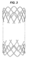
- FIGURE 3 is a perspective view of the two halves, or a crown and mirrored or inverted crown prior to attachment one to the other.
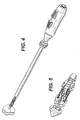
- FIGURE 4 is a perspective view of an applier capable of implantation, actuation and deployment of an anastomotic ring device of FIG. 1, which is retained in an unactuated, cylindrical shape.
- FIGURE 5 is a detail view of the distal tip including an actuating member and piercing tip of the applier of FIG. 4 retaining the anastomotic ring device of FIG. 1 by gripping each point of each respective petal.
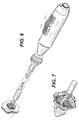
- FIGURE 6 is a perspective the applier of FIG. 4 actuating with opposing, compressive longitudinal actuation motions the anastomotic ring device of FIG. 1 into an actuated hollow rivet, or hour glass, shape to form an anastomotic attachment.
- FIGURE 7 is a detail view of the distal tip of the applier of FIG. 6, depicting the actuated anastomotic ring device having been released from the actuating member in preparation for deployment from the applier.
- FIGURE 8 is a perspective view of hinged anastomotic ring device assembled in an actuated condition from a plurality of molded arcuate petals.
- FIGURE 9 is a perspective view of one molded arcuate petal.
- FIGURE 10 is a perspective view of one half of the hinged anastomotic ring device of FIG. 8 assembled into hinged petals.
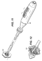
- FIGURE 11 is a perspective view of the applier of FIG. 4 actuating to implant the hinged anastomotic ring device of FIG. 8.
- FIGURE 12 is a detail view of the distal tip of the applier of FIG. 11 depicting the actuated hinged anastomotic ring device having been released from the actuating member in preparation for deployment from the applier.
- FIG. 1 depicts an anastomotic ring device 10 in its generally cylindrical, unactuated condition, with its woven tube of strands resembling the interweaving of a chain link fence.
- a plurality of arcuate members, or petals, 12 are assembled in a longitudinal half, or crown 14, intended to be on one side of an anastomotic attachment site, with a similar but inverted or mirrored crown 16, intended to be on the other side of the anastomotic attachment site.
- Both halves or crowns 14, 16 are attached at a circular midpoint 18 such that the plurality of arcuate members 12 resemble a plurality woven sinusoids.
- attachments 20 respectively between pair of end 22, 24 from an arcuate member 12 in the top crown 14 is made to a respective end 22, 24 of an arcuate member 12 in the bottom crown 16.
- a non-exclusive list of couplings 20 include snap fits, glue, ultrasonic welding, thermal adhesives, etc.
- each arcuate member 12 is included in each crown 14, 16.
- Each arcuate member is woven with two arcuate members to each side and attached to two arcuate members in the other half.
- a left end 22a passes in front (outside) of a right end 24b of a left adjacent arcuate member 12b and then passing behind a right end 24c of a farther left arcuate member 12c, with the pattern repeated about the circumference of the crown 14.
- this number of arcuate members and this degree of interweaving is illustrative and that other patterns consistent with aspects of the invention may be used.
- assembly of the crown 14 is depicted, illustrating how the plurality of arcuate members 12 facilitates economical manufacture that may be performed by automated mechanisms.
- a fixture, or disk, 26 holds the plurality of arcuate members 12 until the crown 14 is complete, specifically locating each pair of ends 22, 24 of each arcuate member 12 for attachment to the other crown 16 (shown in FIG. 3).
- the fixture 26, ensures that each curved point 28, from which each end 22, 24 diverges, is equidistantly spaced about the crown 14 and evenly extending for engagement by an applier.
- an illustrative applier 30 has the anastomotic ring device 12 advantageously retained in a generally cylindrical shape (FIGS. 4-5) distal to an outer tube 32 upon a molded actuation member 34 forming a cannula 36 that distally terminates in a flared tip 38.
- This flared tip 38 presents a distal piercing surface 40 to form an anastomotic opening 42 through apposite tissue walls 44, 46 of two gastrointestinal passages.
- a handle 48, proximal to the cannula 36 includes a pair of longitudinally aligned triggers 50, 52.
- the proximal trigger 50 shown at its most proximal, unfired position, is coupled to proximal leaves 54 of the molded actuation member 34 via an intermediate tube 56 of the cannula 36. Distal movement of the proximal trigger 50 thus causes longitudinal distal movement of the intermediate tube 56 and proximal leaves 54, which outwardly actuate like an umbrella by a hinged relationship to a central portion 58 of the molded actuation member 34. (Unlike an umbrella, the "top" is brought toward the center rather than the converse.)
- distal trigger 42 shown at its most distal, unfired position, is coupled to distal leaves 60 of the molded actuation member 34 via an internal rod 62 that is coupled for movement within the intermediate tube 56.
- Proximal movement of the distal trigger 38 causes longitudinal proximal movement of the rod 62 and distal leaves 64 of the molded actuation member 34, which outwardly actuate by a hinged relationship to the central portion 58.
- the triggers 50, 52 have been slid toward one another to actuate the molded actuating member 34.
- the distal trigger 52 has been moved proximally, causing similar distal movement of the internal rod 62, the distal terminating end of the latter being attached to flared tip 38.
- the flared tip 38 thus moves toward the distal end of the intermediate tube 56.
- the proximal trigger 50 has been moved distally, moving intermediate tube 56 also distally.
- the molded actuating member 34 is compressed between the inwardly moving flared tip 38 and intermediate tube 56.
- the distal leaves 64 actuate lateral to the longitudinal axis, and move toward and interdigitate with the proximal leaves 54. This movement expedites actuating of an anastomotic ring device 10.
- the flared tip 24 of the applier 30 is inserted through a trocar port into a tissue passage that has been placed proximate to another tissue passage that are to be anastomotically joined (See FIGS. 4-5).
- the flared tip 38 and a distal half of the molded actuating member 34 and anastomotic ring device 12 are inserted through an anastomotic opening 42 formed therebetween and then the applier 30 is actuated.
- the proximal and distal leaves 54, 64 are shown as having gripping slots 66 that grip respective curved points 28 of each arcuate member or petals 12 of the anastomotic ring device 12, especially in its unactuated, generally cylindrical shape.
- gripping slots 66 assist in preventing the anastomotic ring device 12 from slipping off of the applier 30 or being inappropriately placed thereon for actuation until fully actuated, forming the anastomotic ring device 12 into a hollow rivet shape or hourglass shape to form the anastomotic attachment between tissue walls 44, 46.
- the fully actuated proximal and distal leaves 54, 64 cause the curved points 28 to disengage from the gripping slots 66.
- the applier 30 is returned to an unactuated condition and the actuated anastomotic ring device 12 deployed by withdrawing the flared tip 38 from the anastomotic opening 42 and ring device 12.
- the unactuated anastomotic ring device 10 may be formed from nitinol and temperature treated to create a Shape Memory Effect that would cause self-actuation after implantation to a hollow rivet or hourglass shape, thus allowing generally known appliers to be used.
- actuation is enhanced or performed entirely by the applier 30 capable of causing the rapid actuation of the anastomotic ring device 10, thus allowing other materials to be used as well as nitinol.
- the ability to cause actuation with an applier 30 enables the use of ring devices with no inherent actuating ability.
- Hinged anastomotic ring device Hinged anastomotic ring device.
- FIGS. 8-10 another anastomotic ring device 110 is formed from molded arcuate members 112 that show further advantages of forming two crowns 114, 116 with attachments 120 at a circular midpoint 118.
- each arcuate member 112 has a first end 122 and a second end 124 convergingly joined at a curved point 128.
- Each first end 122, 124 bends perpendicularly to their respective elongate shafts 130, 132 presenting respectively pin hinge receiving surface 134 and a pin hinge surface 136.
- the pin hinge receiving surface 134 includes a lateral half cylinder recess 138 interposed between a distally presented female attachment feature 140 and a proximally disposed male attachment feature 142.
- the pin hinge surface 136 includes a half pin 144 interposed between a distally disposed female attachment feature 146 and a proximally disposed male attachment feature 148.
- first and second ends 122, 124 of the arcuate member 112 in one crown 114 facilitate a rigid attachment at attachment 120 to rotated identical arcuate members of the other crown 116.
- the joined first ends 122 between the two arcuate members 112 forms a through hole of the two half cylinder recesses 138 that receive a pin hinge formed from two half pins 144 formed from two second ends 124.
- each arcuate member 112 is interwoven with its two adjacent arcuate members 112, moves in concert with its two attached arcuate members 112 in the other crown 116 and is hingedly connected to arcuate members 112 that are on the other side to the adjacent arcuate members 112.
- anastomotic ring device 110 tends to stay in its actuated position.
- the anastomotic ring device 110 is intended to maintain the anastomotic opening and requires a secondary fastening element to remain in the actuated position, such as sutures fastening arcuate members 112 to the tissue and to one another.
- arcuate members 112 may be assembled in an unactuated, cylindrical fashion as previously described above for the wire anastomotic ring device 10, in FIG. 9, it is shown how one crown 114 may be formed in an actuated configuration, readily prepared to accept individual arcuate members 112 of the other crown or a fully assembled bottom crown 116.
- Each molded arcuate member may be formed from a bioabsorbable material, such as a biofragmentable polymer mixture that eventually passes out of the digestive tract.
- a molded arcuate member consistent with aspects of the invention may form a hinged relationship rather than a rigid attachment to respective arcuate members of the inverted crown.
- an anastomosis ring device may include a circular fixture or band at its midpoint for attaching the arcuate members that remains part of the anastomosis ring device, intended to sit at a tissue juncture of the anastomosis.
Landscapes
- Health & Medical Sciences (AREA)
- Surgery (AREA)
- Life Sciences & Earth Sciences (AREA)
- Medical Informatics (AREA)
- Animal Behavior & Ethology (AREA)
- Engineering & Computer Science (AREA)
- Biomedical Technology (AREA)
- Heart & Thoracic Surgery (AREA)
- Physiology (AREA)
- Molecular Biology (AREA)
- Nuclear Medicine, Radiotherapy & Molecular Imaging (AREA)
- General Health & Medical Sciences (AREA)
- Public Health (AREA)
- Veterinary Medicine (AREA)
- Surgical Instruments (AREA)
- Pharmaceuticals Containing Other Organic And Inorganic Compounds (AREA)
- Endoscopes (AREA)
Abstract

Description
- The present application is related to five co-pending and commonly-owned application filed on even date herewith, the disclosure of each is hereby incorporated by reference in its entirety:
- "Anastomosis Wire Ring Device", Serial No. to Don Tanaka, Mark Ortiz and Darrell Powell;
- "Applier For Fastener For Single Lumen Access Anastomosis", Serial No. to Mark Ortiz;
- "Single Lumen Access Deployable Ring for Intralumenal Anastomosis", Serial No. to Mark Ortiz; and
- "Single Lumen Anastamosis Applier for Fastener", Serial No. to Mark Ortiz, Robert McKenna, Bill Kraimer, Mike Stokes, and Foster Stulen.
-
- The present invention relates, in general, to devices and methods for surgically modifying organs and vessels. More particularly, it relates to anastomosis devices for joining two organs such as, for example, two separate lengths of small bowel to each other, a section of small bowel to the stomach, or the common bile duct to the duodenum in a procedure called a choledochoduodenostomy. Vascular anastomosis could be performed as well.
- Creating an anastomosis, or the surgical formation of a passage between two normally distinct vessels, is a critical step of many surgical procedures. This is particularly true of gastric bypass procedures in which two portions of small intestine are joined together and another portion of small intestine is joined to the stomach of the patient. This is also true of surgery to alleviate blockage in the common bile duct by draining bile from the duct to the small intestine during surgery for pancreatic cancer.
- The percentage of the world population suffering from morbid obesity is steadily increasing. Severely obese persons are susceptible to increased risk of heart disease, stroke, diabetes, pulmonary disease, and accidents. Because of the effect of morbid obesity to the life of the patient, methods of treating morbid obesity are being researched.
- Numerous non-operative therapies for morbid obesity have been tried with virtually no permanent success. Dietary counseling, behavior modification, wiring a patient's jaws shut, and pharmacologic methods have all been tried, and though temporarily effective, failed to correct the condition. Further, introducing an object in the stomach, such as an esophago-gastric balloon, to fill the stomach have also been used to treat the condition; however, such approaches tend to cause irritation to the stomach and are not effective long-term.
- Surgical treatments of morbid obesity have been increasingly used with greater success. These approaches may be generalized as those that reduce the effective size of the stomach, limiting the amount of food intake, and those that create malabsorption of the food that it is eaten. For instance, some patients benefit from adjustable gastric bands (AGB) that are advantageously laparoscopically placed about the stomach to form a stoma of a desired size that allows food to fill an upper portion of the stomach, causing a feeling of satiety. To allow adjustment of the size of the stoma after implantation, a fluid conduit communicates between an inwardly presented fluid bladder of the AGB to a fluid injection port subcutaneously placed in front of the patient's sternum. A syringe needle may then inject or withdraw fluid as desired to adjust the AGB.
- Although an effective approach to obesity for some, other patients may find the lifestyle changes undesirable, necessitated by the restricted amount of food intake. In addition, the medical condition of the patient may suggest the need for a more permanent solution. To that end, surgical approaches have been used to alter the portions of the stomach and/or small intestine available for digesting food. Current methods of performing a laparoscopic anastomoses for a gastric bypass include stapling, suturing, and placing biofragmentable rings, each having significant challenges. For instance, suturing is time consuming, as well as being technique and dexterity dependent. Stapling requires placement of an anvil, which is a large device that cannot be introduced through a trocar port. Having to introduce the port through a laparotomy presents an increased incidence of wound site infection associated with intralumenal content being dragged to the laparotomy entry site.
- As an example of the latter approach, in U.S. Pat. No. 6,543,456 a method for gastric bypass surgery includes the insertion of proximal and distal anastomosis members (e.g., anvils) transorally with grasping forceps. The stomach and the small intestine are transected endoscopically by a surgical severing and stapling instrument to create a gastric pouch, a drainage loop, and a Roux limb. An endoscopically inserted circular stapler attaches to the distal anastomosis member to join the drainage loop to a distal portion of the intestine, and the circular stapler attaches to the proximal anastomosis member to join the Roux limb to the gastric pouch. Thereafter, the anastomosis members are removed to create an orifice between joined portions of the stomach and intestine. This method reduces the number of laparoscopic ports, avoids a laparoscopic insertion of an anastomosis instrument (e.g., circular stapler) into an enlarged surgical port, and eliminates the need for an enterotomy and an enterotomy closure.
- For many anastomoses, surgeons use circular staplers, linear staplers, or manual sutures. However, to reduce incision size and to make the surgical process less technically demanding and time consuming, an anastomotic device that deforms to hold tissue portions together when the device is ejected from a constraining enclosure has been described. Such an approach is described in U.S. Pat. Appl. Publ. No. US 2003/0032967 and PCT application WO 03/000142 both to Adrian Park et al, which is hereby incorporated herein by reference, describes such a device. Therein, gastrointestinal or enteric (including biliary) anastomosis is achieved by insertion of a sheath that perforates the walls of two tissue passages, such as the stomach and small intestine. A three-dimensional woven tube of wire of having a thermal shape memory effect (SME) ("generally-known nitinol ring device") is presented by a cannula of the sheath on both sides of the openings. Deployment of the woven tube causes the outer loops or ends of the tube to fold or loop back to hold the luminal interface of the anastomosis site in apposition. Thereby, the need for a mechanical compression component in a delivery system is reduced or avoided, reducing the size and complexity of the delivery device.
- The anastomotic device disclosed in WO 03/000142 is constrained by a retractable sheath to an advantageous small-diameter tubular shape. A surgeon applies the anastomotic device by maneuvering the sheath through the tissue portions requiring anastomosis and retracting the sheath. Retracting the sheath removes the constraint on the device, allowing the device to assume a roughly hourglass shape. The larger ends of the hourglass shape hold the two tissue portions together in an effective anastomosis.
- The constrained anastomotic device, which may be made of a shape memory material such as nitinol, exerts a force against the inner diameter of the sheath and tends to warp towards its roughly hourglass-shaped deployed position. When the sheath is retracted proximally, the forces generated by the device in transition from a tubular shape to an hourglass shape urge the anastomotic device distally. This device movement makes surgical control harder to achieve when placing the device through the otomies of two tissue portions requiring anastomosis.
- While the generally-known nitinol ring device is a significant advancement in the treatment of morbid obesity, it is believed that further improvements would be desirable. For instance, the continuous interlocking petals are difficult to manufacturer, especially since the depicted woven tube is of a continuous wire loop bent into a pattern of interlocking triangles that are hand woven from two wire strands and the four free ends connected to one another.
- Consequently, there is a general need for an approach to making an anastomosis ring device that can be used in existing trocar ports (e.g., 12 mm size) and that reliably and effectively creates an anastomotic attachment between lumens, eliminate the need for surgical stapling and suturing to form an anastomosis.
- The invention overcomes the above-noted and other deficiencies of the prior art by providing a method of making an anastomotic ring device of interlocking sinusoidal members in a cylindrical shape (undeployed) that readily converts to a hollow rivet shape (deployed), or "hour glass shape", for endoscopic surgical procedures. In particular, each anastomotic ring device is assembled from a plurality of "points", or arcuate members. These components allow for a proximal and distal longitudinal halves (i.e., "crowns") of the ring device to be assembled individually and joined together, which lends itself for simplified manufacture.
- In one aspect of the invention, a longitudinally bisected ring device is assembled from arcuate members of a deformable material (e.g., nitinol or other alloy). Each arcuate member is of identical or similar points (e.g., two diverging legs joined at an acutely bent radius). One crown is formed by placing half of the arcuate members (e.g., 10) in cylindrical configuration, overlapping each leg with the leg of an adjacent arcuate member. The crown may be held in a fixture until mated to another crown that is inverted to the first. The longitudinally bisected ring device thus formed in its undeployed, cylindrical shape may receive further processing to impart an ability to actuate to a hollow rivet shape to hold two tissue lumens at an anastomotic attachment.
- In another aspect of the invention, such a method of implanting the longitudinally bisected ring device includes not having to rely solely or at all upon an intrinsic actuation potential. Instead, an actuator member of an applier is capable of receiving the cylindrical, undeployed shape of the ring device. When inserted across the anastomotic attachment site, the applier actuates the actuator member by compressing the ring device into a hollow rivet shape.
- In yet another aspect of the invention, a longitudinally bisected ring device is formed from molded arcuate members assembled into interlocking cylindrical sinusoids that hingedly attach with adjacent arcuate members in their same longitudinal half of the ring device and rigidly attach to inverted arcuate members in the other longitudinal half. These molded arcuate members advantageously lend themselves to assembly in a deployed configuration. The ability for the interlocking sinusoids to hinge, allowing overlapping petals to move between cylindrical orientation and hollow rivet shape, lend themselves to implantation at an anastomotic surgical site, such as with the afore-described applier.
- These and other objects and advantages of the present invention shall be made apparent from the accompanying drawings and the description thereof.
- The accompanying drawings, which are incorporated in and constitute a part of this specification, illustrate embodiments of the invention, and, together with the general description of the invention given above, and the detailed description of the embodiments given below, serve to explain the principles of the present invention.
- FIGURE 1 is perspective view of an anastomotic ring device assembled from a plurality of arcuate petals.
- FIGURE 2 is a perspective view of one longitudinal half, or "crown" of the anastomotic ring device of FIG. 1 being assembled onto a fixture.
- FIGURE 3 is a perspective view of the two halves, or a crown and mirrored or inverted crown prior to attachment one to the other.
- FIGURE 4 is a perspective view of an applier capable of implantation, actuation and deployment of an anastomotic ring device of FIG. 1, which is retained in an unactuated, cylindrical shape.
- FIGURE 5 is a detail view of the distal tip including an actuating member and piercing tip of the applier of FIG. 4 retaining the anastomotic ring device of FIG. 1 by gripping each point of each respective petal.
- FIGURE 6 is a perspective the applier of FIG. 4 actuating with opposing, compressive longitudinal actuation motions the anastomotic ring device of FIG. 1 into an actuated hollow rivet, or hour glass, shape to form an anastomotic attachment.
- FIGURE 7 is a detail view of the distal tip of the applier of FIG. 6, depicting the actuated anastomotic ring device having been released from the actuating member in preparation for deployment from the applier.
- FIGURE 8 is a perspective view of hinged anastomotic ring device assembled in an actuated condition from a plurality of molded arcuate petals.
- FIGURE 9 is a perspective view of one molded arcuate petal.
- FIGURE 10 is a perspective view of one half of the hinged anastomotic ring device of FIG. 8 assembled into hinged petals.
- FIGURE 11 is a perspective view of the applier of FIG. 4 actuating to implant the hinged anastomotic ring device of FIG. 8.
- FIGURE 12 is a detail view of the distal tip of the applier of FIG. 11 depicting the actuated hinged anastomotic ring device having been released from the actuating member in preparation for deployment from the applier.
- Turning to the Drawings, wherein like numerals denote like components throughout the several views, FIG. 1 depicts an
anastomotic ring device 10 in its generally cylindrical, unactuated condition, with its woven tube of strands resembling the interweaving of a chain link fence. In the illustrative embodiment, a plurality of arcuate members, or petals, 12 are assembled in a longitudinal half, orcrown 14, intended to be on one side of an anastomotic attachment site, with a similar but inverted or mirroredcrown 16, intended to be on the other side of the anastomotic attachment site. - Both halves or crowns 14, 16 are attached at a
circular midpoint 18 such that the plurality ofarcuate members 12 resemble a plurality woven sinusoids. At themidpoint 18, attachments 20 respectively between pair ofend arcuate member 12 in thetop crown 14 is made to arespective end arcuate member 12 in thebottom crown 16. A non-exclusive list of couplings 20 include snap fits, glue, ultrasonic welding, thermal adhesives, etc. - In the illustrative ring device of FIG. 1, ten
arcuate members 12 are included in eachcrown arcuate member 12a, a left end 22a passes in front (outside) of a right end 24b of a left adjacentarcuate member 12b and then passing behind a right end 24c of a farther leftarcuate member 12c, with the pattern repeated about the circumference of thecrown 14. It should be appreciated that this number of arcuate members and this degree of interweaving is illustrative and that other patterns consistent with aspects of the invention may be used. - In FIG. 2, assembly of the
crown 14 is depicted, illustrating how the plurality ofarcuate members 12 facilitates economical manufacture that may be performed by automated mechanisms. In this depiction, a fixture, or disk, 26 holds the plurality ofarcuate members 12 until thecrown 14 is complete, specifically locating each pair ofends arcuate member 12 for attachment to the other crown 16 (shown in FIG. 3). Moreover, the fixture 26, ensures that eachcurved point 28, from which eachend crown 14 and evenly extending for engagement by an applier. - In FIGS. 4-7, an
illustrative applier 30 has theanastomotic ring device 12 advantageously retained in a generally cylindrical shape (FIGS. 4-5) distal to an outer tube 32 upon a molded actuation member 34 forming a cannula 36 that distally terminates in a flared tip 38. This flared tip 38 presents a distal piercing surface 40 to form an anastomotic opening 42 through apposite tissue walls 44, 46 of two gastrointestinal passages. - With particular reference to FIG. 6, a handle 48, proximal to the cannula 36, includes a pair of longitudinally aligned triggers 50, 52. The proximal trigger 50, shown at its most proximal, unfired position, is coupled to proximal leaves 54 of the molded actuation member 34 via an intermediate tube 56 of the cannula 36. Distal movement of the proximal trigger 50 thus causes longitudinal distal movement of the intermediate tube 56 and proximal leaves 54, which outwardly actuate like an umbrella by a hinged relationship to a central portion 58 of the molded actuation member 34. (Unlike an umbrella, the "top" is brought toward the center rather than the converse.)
- Similarly, the distal trigger 42, shown at its most distal, unfired position, is coupled to distal leaves 60 of the molded actuation member 34 via an internal rod 62 that is coupled for movement within the intermediate tube 56. Proximal movement of the distal trigger 38 causes longitudinal proximal movement of the rod 62 and distal leaves 64 of the molded actuation member 34, which outwardly actuate by a hinged relationship to the central portion 58.
- In FIGS. 6-7, the triggers 50, 52 have been slid toward one another to actuate the molded actuating member 34. Specifically, the distal trigger 52 has been moved proximally, causing similar distal movement of the internal rod 62, the distal terminating end of the latter being attached to flared tip 38. The flared tip 38 thus moves toward the distal end of the intermediate tube 56. The proximal trigger 50 has been moved distally, moving intermediate tube 56 also distally. The molded actuating member 34 is compressed between the inwardly moving flared tip 38 and intermediate tube 56. The distal leaves 64 actuate lateral to the longitudinal axis, and move toward and interdigitate with the proximal leaves 54. This movement expedites actuating of an
anastomotic ring device 10. - In use, the flared
tip 24 of theapplier 30 is inserted through a trocar port into a tissue passage that has been placed proximate to another tissue passage that are to be anastomotically joined (See FIGS. 4-5). The flared tip 38 and a distal half of the molded actuating member 34 andanastomotic ring device 12 are inserted through an anastomotic opening 42 formed therebetween and then theapplier 30 is actuated. With particular reference to FIGS. 6-7, the proximal and distal leaves 54, 64 are shown as having gripping slots 66 that grip respectivecurved points 28 of each arcuate member orpetals 12 of theanastomotic ring device 12, especially in its unactuated, generally cylindrical shape. These gripping slots 66 assist in preventing theanastomotic ring device 12 from slipping off of theapplier 30 or being inappropriately placed thereon for actuation until fully actuated, forming theanastomotic ring device 12 into a hollow rivet shape or hourglass shape to form the anastomotic attachment between tissue walls 44, 46. The fully actuated proximal and distal leaves 54, 64 cause thecurved points 28 to disengage from the gripping slots 66. Thereafter, theapplier 30 is returned to an unactuated condition and the actuatedanastomotic ring device 12 deployed by withdrawing the flared tip 38 from the anastomotic opening 42 andring device 12. - It should be appreciated that the unactuated
anastomotic ring device 10 may be formed from nitinol and temperature treated to create a Shape Memory Effect that would cause self-actuation after implantation to a hollow rivet or hourglass shape, thus allowing generally known appliers to be used. However, as described above and in more detail in the above-referenced co-pending application entitled "Single Lumen Anastamosis Applier for Self-Deploying Fastener" to M. Ortiz, such actuation is enhanced or performed entirely by theapplier 30 capable of causing the rapid actuation of theanastomotic ring device 10, thus allowing other materials to be used as well as nitinol. Moreover, the ability to cause actuation with anapplier 30 enables the use of ring devices with no inherent actuating ability. - For instance, in FIGS. 8-10, another
anastomotic ring device 110 is formed from moldedarcuate members 112 that show further advantages of forming two crowns 114, 116 withattachments 120 at a circular midpoint 118. With particular reference to FIG. 9, eacharcuate member 112 has afirst end 122 and asecond end 124 convergingly joined at acurved point 128. Eachfirst end elongate shafts 130, 132 presenting respectively pinhinge receiving surface 134 and apin hinge surface 136. The pinhinge receiving surface 134 includes a lateralhalf cylinder recess 138 interposed between a distally presentedfemale attachment feature 140 and a proximally disposedmale attachment feature 142. Thepin hinge surface 136 includes a half pin 144 interposed between a distally disposed female attachment feature 146 and a proximally disposed male attachment feature 148. - These first and second ends 122, 124 of the
arcuate member 112 in one crown 114 facilitate a rigid attachment atattachment 120 to rotated identical arcuate members of the other crown 116. The joined first ends 122 between the twoarcuate members 112 forms a through hole of the two half cylinder recesses 138 that receive a pin hinge formed from two half pins 144 formed from two second ends 124. Thus eacharcuate member 112 is interwoven with its two adjacentarcuate members 112, moves in concert with its two attachedarcuate members 112 in the other crown 116 and is hingedly connected toarcuate members 112 that are on the other side to the adjacentarcuate members 112. - Sufficient friction exists in the hinged connection between arcuate members at the midpoint 118 that when placed in position, such as depicted in FIGS. 11-12 by an
applier 30, theanastomotic ring device 110 tends to stay in its actuated position. Alternatively, theanastomotic ring device 110 is intended to maintain the anastomotic opening and requires a secondary fastening element to remain in the actuated position, such as sutures fasteningarcuate members 112 to the tissue and to one another. - Although such molded
arcuate members 112 may be assembled in an unactuated, cylindrical fashion as previously described above for the wireanastomotic ring device 10, in FIG. 9, it is shown how one crown 114 may be formed in an actuated configuration, readily prepared to accept individualarcuate members 112 of the other crown or a fully assembled bottom crown 116. - Each molded arcuate member may be formed from a bioabsorbable material, such as a biofragmentable polymer mixture that eventually passes out of the digestive tract.
- While the present invention has been illustrated by description of several embodiments and while the illustrative embodiments have been described in considerable detail, it is not the intention of the applicant to restrict or in any way limit the scope of the appended claims to such detail. Additional advantages and modifications may readily appear to those skilled in the art.
- For example, a molded arcuate member consistent with aspects of the invention may form a hinged relationship rather than a rigid attachment to respective arcuate members of the inverted crown.
- As a further example, an anastomosis ring device may include a circular fixture or band at its midpoint for attaching the arcuate members that remains part of the anastomosis ring device, intended to sit at a tissue juncture of the anastomosis.
Claims (10)
- An anastomosis device, comprising:wherein the woven tube thus formed is operably configured to transform into a second position comprising a hollow rivet shape with each arcuate member outwardly deflected from a longitudinal axis of its respective cylindrical crown toward apposing arcuate members of the other cylindrical crown.a first plurality of arcuate members arranged in a first position in a cylindrical crown shape with each arcuate member having legs overlapping at least one adjacent arcuate member; anda second plurality of arcuate members arranged in a first position in an inverted cylindrical crown shape with each arcuate member having legs overlapping at least one adjacent arcuate member of the second plurality and connected to a leg of an arcuate member of the first plurality;
- The anastomosis device of claim 1, wherein the arcuate members comprise a shape memory effect alloy.
- The anastomosis device of claim 1, wherein the legs of the arcuate members of the first plurality are attached to the respective arcuate member of the second plurality by a connecting member.
- The anastomosis device of claim 3, wherein the connecting members comprises a selected one of a group consisting of a snap fit, a glue, an ultrasonically welded portion, and a thermally melted polymer.
- The anastomosis device of claim 3, wherein the legs of the arcuate members of the first plurality are attached to the respective arcuate member of the second plurality by a rigid connecting member, a petal formed by the first arcuate member actuating generally in a plane with the respective attached arcuate members pivoting about a cylindrical midpoint of the anastomosis device.
- The anastomosis device of claim 5, wherein each leg is further hingedly coupled at the circular midpoint of the anastomosis device to at least one other leg.
- The anastomosis device of claim 3, wherein the legs of the arcuate members of the first plurality are attached to the respective arcuate member of the second plurality by a pivotal connecting member.
- The anastomosis device of claim 3, wherein the connecting member comprises a band at a midpoint of the device connected to each arcuate member.
- An anastomosis ring device, comprising:a means for forming a half cylindrical which actuates into a first apposing member about a midpoint at an anastomosis tissue juncture; anda means for forming an inverted half cylinder which actuates into a second apposing member at the midpoint at the anastomosis tissue juncture.
- An anastomosis ring device, comprising a plurality of arcuate members operably configured to be arranged into two crowns attached to one another to present petal circumferentially hinged at a circular midpoint, each arcuate member comprising a pair of diverging connected legs.
Applications Claiming Priority (2)
| Application Number | Priority Date | Filing Date | Title |
|---|---|---|---|
| US675091 | 2003-09-30 | ||
| US10/675,091 US20050070939A1 (en) | 2003-09-30 | 2003-09-30 | Unfolding anastomosis ring device |
Publications (2)
| Publication Number | Publication Date |
|---|---|
| EP1520529A1 true EP1520529A1 (en) | 2005-04-06 |
| EP1520529B1 EP1520529B1 (en) | 2006-11-02 |
Family
ID=34313981
Family Applications (1)
| Application Number | Title | Priority Date | Filing Date |
|---|---|---|---|
| EP04256038A Expired - Lifetime EP1520529B1 (en) | 2003-09-30 | 2004-09-30 | Unfolding anastomosis ring device |
Country Status (11)
| Country | Link |
|---|---|
| US (1) | US20050070939A1 (en) |
| EP (1) | EP1520529B1 (en) |
| JP (1) | JP2005103302A (en) |
| CN (1) | CN1647772A (en) |
| AT (1) | ATE343971T1 (en) |
| AU (2) | AU2004216631A1 (en) |
| BR (1) | BRPI0404196B8 (en) |
| CA (1) | CA2483238C (en) |
| DE (1) | DE602004003012T2 (en) |
| ES (1) | ES2276238T3 (en) |
| MX (1) | MXPA04009611A (en) |
Cited By (1)
| Publication number | Priority date | Publication date | Assignee | Title |
|---|---|---|---|---|
| EP1719453A1 (en) * | 2005-05-03 | 2006-11-08 | Ethicon Endo-Surgery, Inc. | Anastomosis applier |
Families Citing this family (28)
| Publication number | Priority date | Publication date | Assignee | Title |
|---|---|---|---|---|
| US7452363B2 (en) * | 2003-09-30 | 2008-11-18 | Ethicon Endo-Surgery, Inc. | Applier for fastener for single lumen access anastomosis |
| US7309341B2 (en) * | 2003-09-30 | 2007-12-18 | Ethicon Endo-Surgery, Inc. | Single lumen anastomosis applier for self-deploying fastener |
| US7608086B2 (en) * | 2003-09-30 | 2009-10-27 | Ethicon Endo-Surgery, Inc. | Anastomosis wire ring device |
| US8211142B2 (en) * | 2003-09-30 | 2012-07-03 | Ortiz Mark S | Method for hybrid gastro-jejunostomy |
| US7618427B2 (en) * | 2003-12-29 | 2009-11-17 | Ethicon Endo-Surgery, Inc. | Device and method for intralumenal anastomosis |
| US7462186B2 (en) * | 2005-05-03 | 2008-12-09 | Ethicon Endo-Surgery, Inc. | Anastomotic ring applier device utilizing an electroactive polymer |
| US7470275B2 (en) * | 2005-05-03 | 2008-12-30 | Ethicon Endo-Surgery, Inc. | Anastomotic ring applier device providing forward and retrograde visualization |
| US7632285B2 (en) * | 2005-05-03 | 2009-12-15 | Ethicon Endo-Surgery, Inc. | Sheath for enabling insertion and extraction of anastomotic ring applier |
| US7645287B2 (en) * | 2005-05-03 | 2010-01-12 | Ethicon Endo-Surgery, Inc. | Articulating anastomotic ring applier |
| US7645288B2 (en) * | 2005-05-05 | 2010-01-12 | Ethicon Endo-Surgery, Inc. | Anastomotic ring applier with inflatable members |
| US7691113B2 (en) * | 2005-05-05 | 2010-04-06 | Ethicon Endo-Surgery, Inc. | Screw tip control for anastomotic ring applier |
| US7445622B2 (en) * | 2005-05-05 | 2008-11-04 | Ethicon Endo-Surgery, Inc. | Anastomotic ring applier with double motion actuation |
| US20070021759A1 (en) * | 2005-07-22 | 2007-01-25 | Ethicon Endo-Surgery, Inc. | Flexible endoscopic anastomotic ring applier device |
| US20070021758A1 (en) * | 2005-07-22 | 2007-01-25 | Ethicon Endo-Surgery, Inc. | Anastomotic ring applier for use in colorectal applications |
| US8029522B2 (en) * | 2005-08-05 | 2011-10-04 | Ethicon Endo-Surgery, Inc. | Method and apparatus for sealing a gastric opening |
| US20070123917A1 (en) * | 2005-11-29 | 2007-05-31 | Ortiz Mark S | Anastomotic device promoting tissue necrosis |
| US8603138B2 (en) * | 2006-10-04 | 2013-12-10 | Ethicon Endo-Surgery, Inc. | Use of an adhesive to treat intraluminal bleeding |
| US7914511B2 (en) * | 2006-10-18 | 2011-03-29 | Ethicon Endo-Surgery, Inc. | Use of biosurgical adhesive as bulking agent |
| US8876844B2 (en) * | 2006-11-01 | 2014-11-04 | Ethicon Endo-Surgery, Inc. | Anastomosis reinforcement using biosurgical adhesive and device |
| US20100276469A1 (en) * | 2009-05-01 | 2010-11-04 | Barosense, Inc. | Plication tagging device and method |
| US8623040B2 (en) | 2009-07-01 | 2014-01-07 | Alcon Research, Ltd. | Phacoemulsification hook tip |
| WO2012007042A1 (en) | 2010-07-16 | 2012-01-19 | Ethicon Endo-Surgery, Inc. | An anastomosis device for a cholecysto-enterostomy |
| KR101213293B1 (en) | 2010-08-23 | 2012-12-18 | 이영삼 | Anastomosis apparatus for tubular organ |
| US10258505B2 (en) | 2010-09-17 | 2019-04-16 | Alcon Research, Ltd. | Balanced phacoemulsification tip |
| US9907600B2 (en) * | 2013-11-15 | 2018-03-06 | Ethicon Llc | Ultrasonic anastomosis instrument with piezoelectric sealing head |
| US11344325B2 (en) * | 2017-09-30 | 2022-05-31 | Ceretrive Ltd. | Retrieval system |
| WO2019204167A1 (en) * | 2018-04-17 | 2019-10-24 | Ruebeck David | Device and method for connecting tubular structures |
| CN113500679A (en) * | 2021-05-08 | 2021-10-15 | 沅江市琼湖棉麻有限公司 | Production process of soft elastic fibrilia board |
Citations (5)
| Publication number | Priority date | Publication date | Assignee | Title |
|---|---|---|---|---|
| WO1999021491A1 (en) * | 1997-10-24 | 1999-05-06 | Suyker Wilhelmus Jospeh Leonar | Mechanical anastomosis system for hollow structures |
| WO2000012832A2 (en) * | 1998-08-26 | 2000-03-09 | Molecular Geodesics, Inc. | Radially expandable device |
| WO2003000142A2 (en) | 2001-06-20 | 2003-01-03 | Park Medical, Llc. | Anastomotic device |
| US6543456B1 (en) | 2002-05-31 | 2003-04-08 | Ethicon Endo-Surgery, Inc. | Method for minimally invasive surgery in the digestive system |
| US20030109893A1 (en) * | 2001-12-06 | 2003-06-12 | Cardica,Inc. | Implantable medical device such as an anastomosis device |
Family Cites Families (10)
| Publication number | Priority date | Publication date | Assignee | Title |
|---|---|---|---|---|
| DE4334140C2 (en) * | 1993-10-07 | 1996-04-18 | Angiomed Ag | Stent and device with stent |
| IL125416A0 (en) * | 1996-02-02 | 1999-03-12 | Transvascular Inc | Methods and apparatus for connecting openings formed in adjacent blood vessels or other anatomical structures |
| EP2258312B9 (en) * | 1997-12-29 | 2012-09-19 | The Cleveland Clinic Foundation | Deployable surgical platform and system for the removal and delivery of a medical device comprising such deployable surgical platform |
| US6551344B2 (en) * | 2000-04-26 | 2003-04-22 | Ev3 Inc. | Septal defect occluder |
| US7115136B2 (en) * | 2001-06-20 | 2006-10-03 | Park Medical Llc | Anastomotic device |
| US20050038497A1 (en) * | 2003-08-11 | 2005-02-17 | Scimed Life Systems, Inc. | Deformation medical device without material deformation |
| US20050070935A1 (en) * | 2003-09-30 | 2005-03-31 | Ortiz Mark S. | Single lumen access deployable ring for intralumenal anastomosis |
| US7309341B2 (en) * | 2003-09-30 | 2007-12-18 | Ethicon Endo-Surgery, Inc. | Single lumen anastomosis applier for self-deploying fastener |
| US7608086B2 (en) * | 2003-09-30 | 2009-10-27 | Ethicon Endo-Surgery, Inc. | Anastomosis wire ring device |
| US7452363B2 (en) * | 2003-09-30 | 2008-11-18 | Ethicon Endo-Surgery, Inc. | Applier for fastener for single lumen access anastomosis |
-
2003
- 2003-09-30 US US10/675,091 patent/US20050070939A1/en not_active Abandoned
-
2004
- 2004-09-29 CN CNA2004100874825A patent/CN1647772A/en active Pending
- 2004-09-30 CA CA2483238A patent/CA2483238C/en not_active Expired - Fee Related
- 2004-09-30 DE DE602004003012T patent/DE602004003012T2/en not_active Expired - Lifetime
- 2004-09-30 AU AU2004216631A patent/AU2004216631A1/en not_active Abandoned
- 2004-09-30 JP JP2004288267A patent/JP2005103302A/en not_active Ceased
- 2004-09-30 EP EP04256038A patent/EP1520529B1/en not_active Expired - Lifetime
- 2004-09-30 MX MXPA04009611A patent/MXPA04009611A/en unknown
- 2004-09-30 BR BRPI0404196A patent/BRPI0404196B8/en not_active IP Right Cessation
- 2004-09-30 AT AT04256038T patent/ATE343971T1/en not_active IP Right Cessation
- 2004-09-30 ES ES04256038T patent/ES2276238T3/en not_active Expired - Lifetime
-
2011
- 2011-05-20 AU AU2011202357A patent/AU2011202357B2/en not_active Ceased
Patent Citations (6)
| Publication number | Priority date | Publication date | Assignee | Title |
|---|---|---|---|---|
| WO1999021491A1 (en) * | 1997-10-24 | 1999-05-06 | Suyker Wilhelmus Jospeh Leonar | Mechanical anastomosis system for hollow structures |
| WO2000012832A2 (en) * | 1998-08-26 | 2000-03-09 | Molecular Geodesics, Inc. | Radially expandable device |
| WO2003000142A2 (en) | 2001-06-20 | 2003-01-03 | Park Medical, Llc. | Anastomotic device |
| US20030032967A1 (en) | 2001-06-20 | 2003-02-13 | Park Medical, Llc | Anastomotic device |
| US20030109893A1 (en) * | 2001-12-06 | 2003-06-12 | Cardica,Inc. | Implantable medical device such as an anastomosis device |
| US6543456B1 (en) | 2002-05-31 | 2003-04-08 | Ethicon Endo-Surgery, Inc. | Method for minimally invasive surgery in the digestive system |
Cited By (2)
| Publication number | Priority date | Publication date | Assignee | Title |
|---|---|---|---|---|
| EP1719453A1 (en) * | 2005-05-03 | 2006-11-08 | Ethicon Endo-Surgery, Inc. | Anastomosis applier |
| US7547311B2 (en) | 2005-05-03 | 2009-06-16 | Ethicon Endo-Surgery, Inc. | Spring-based firing mechanism for anastomotic ring applier |
Also Published As
| Publication number | Publication date |
|---|---|
| DE602004003012D1 (en) | 2006-12-14 |
| ATE343971T1 (en) | 2006-11-15 |
| DE602004003012T2 (en) | 2007-05-31 |
| AU2011202357A1 (en) | 2011-06-09 |
| CN1647772A (en) | 2005-08-03 |
| ES2276238T3 (en) | 2007-06-16 |
| CA2483238C (en) | 2012-06-19 |
| BRPI0404196B8 (en) | 2021-06-22 |
| BRPI0404196B1 (en) | 2018-05-29 |
| BRPI0404196A (en) | 2005-06-07 |
| AU2004216631A1 (en) | 2005-04-14 |
| JP2005103302A (en) | 2005-04-21 |
| EP1520529B1 (en) | 2006-11-02 |
| AU2011202357B2 (en) | 2012-04-19 |
| MXPA04009611A (en) | 2005-06-08 |
| US20050070939A1 (en) | 2005-03-31 |
| CA2483238A1 (en) | 2005-03-30 |
Similar Documents
| Publication | Publication Date | Title |
|---|---|---|
| AU2011202357B2 (en) | Unfolding anastomosis ring device | |
| CA2483726C (en) | Single lumen access deployable ring for intralumenal anastomosis | |
| US7452363B2 (en) | Applier for fastener for single lumen access anastomosis | |
| EP1520528B1 (en) | Anastomosis wire ring device | |
| US7309341B2 (en) | Single lumen anastomosis applier for self-deploying fastener | |
| US8211142B2 (en) | Method for hybrid gastro-jejunostomy | |
| AU2007201158B2 (en) | Method for hybrid gastro-jejunostomy | |
| AU2011202587A1 (en) | Anastomosis wire ring device |
Legal Events
| Date | Code | Title | Description |
|---|---|---|---|
| PUAI | Public reference made under article 153(3) epc to a published international application that has entered the european phase |
Free format text: ORIGINAL CODE: 0009012 |
|
| AK | Designated contracting states |
Kind code of ref document: A1 Designated state(s): AT BE BG CH CY CZ DE DK EE ES FI FR GB GR HU IE IT LI LU MC NL PL PT RO SE SI SK TR |
|
| AX | Request for extension of the european patent |
Extension state: AL HR LT LV MK |
|
| 17P | Request for examination filed |
Effective date: 20051003 |
|
| AKX | Designation fees paid |
Designated state(s): AT BE BG CH CY CZ DE DK EE ES FI FR GB GR HU IE IT LI LU MC NL PL PT RO SE SI SK TR |
|
| GRAP | Despatch of communication of intention to grant a patent |
Free format text: ORIGINAL CODE: EPIDOSNIGR1 |
|
| GRAS | Grant fee paid |
Free format text: ORIGINAL CODE: EPIDOSNIGR3 |
|
| GRAA | (expected) grant |
Free format text: ORIGINAL CODE: 0009210 |
|
| AK | Designated contracting states |
Kind code of ref document: B1 Designated state(s): AT BE BG CH CY CZ DE DK EE ES FI FR GB GR HU IE IT LI LU MC NL PL PT RO SE SI SK TR |
|
| PG25 | Lapsed in a contracting state [announced via postgrant information from national office to epo] |
Ref country code: FI Free format text: LAPSE BECAUSE OF FAILURE TO SUBMIT A TRANSLATION OF THE DESCRIPTION OR TO PAY THE FEE WITHIN THE PRESCRIBED TIME-LIMIT Effective date: 20061102 Ref country code: CZ Free format text: LAPSE BECAUSE OF FAILURE TO SUBMIT A TRANSLATION OF THE DESCRIPTION OR TO PAY THE FEE WITHIN THE PRESCRIBED TIME-LIMIT Effective date: 20061102 Ref country code: SK Free format text: LAPSE BECAUSE OF FAILURE TO SUBMIT A TRANSLATION OF THE DESCRIPTION OR TO PAY THE FEE WITHIN THE PRESCRIBED TIME-LIMIT Effective date: 20061102 Ref country code: CH Free format text: LAPSE BECAUSE OF FAILURE TO SUBMIT A TRANSLATION OF THE DESCRIPTION OR TO PAY THE FEE WITHIN THE PRESCRIBED TIME-LIMIT Effective date: 20061102 Ref country code: LI Free format text: LAPSE BECAUSE OF FAILURE TO SUBMIT A TRANSLATION OF THE DESCRIPTION OR TO PAY THE FEE WITHIN THE PRESCRIBED TIME-LIMIT Effective date: 20061102 Ref country code: BE Free format text: LAPSE BECAUSE OF FAILURE TO SUBMIT A TRANSLATION OF THE DESCRIPTION OR TO PAY THE FEE WITHIN THE PRESCRIBED TIME-LIMIT Effective date: 20061102 Ref country code: RO Free format text: LAPSE BECAUSE OF FAILURE TO SUBMIT A TRANSLATION OF THE DESCRIPTION OR TO PAY THE FEE WITHIN THE PRESCRIBED TIME-LIMIT Effective date: 20061102 Ref country code: SI Free format text: LAPSE BECAUSE OF FAILURE TO SUBMIT A TRANSLATION OF THE DESCRIPTION OR TO PAY THE FEE WITHIN THE PRESCRIBED TIME-LIMIT Effective date: 20061102 Ref country code: AT Free format text: LAPSE BECAUSE OF FAILURE TO SUBMIT A TRANSLATION OF THE DESCRIPTION OR TO PAY THE FEE WITHIN THE PRESCRIBED TIME-LIMIT Effective date: 20061102 Ref country code: PL Free format text: LAPSE BECAUSE OF FAILURE TO SUBMIT A TRANSLATION OF THE DESCRIPTION OR TO PAY THE FEE WITHIN THE PRESCRIBED TIME-LIMIT Effective date: 20061102 |
|
| REG | Reference to a national code |
Ref country code: GB Ref legal event code: FG4D |
|
| REG | Reference to a national code |
Ref country code: IE Ref legal event code: FG4D |
|
| REG | Reference to a national code |
Ref country code: CH Ref legal event code: EP |
|
| REF | Corresponds to: |
Ref document number: 602004003012 Country of ref document: DE Date of ref document: 20061214 Kind code of ref document: P |
|
| PG25 | Lapsed in a contracting state [announced via postgrant information from national office to epo] |
Ref country code: DK Free format text: LAPSE BECAUSE OF FAILURE TO SUBMIT A TRANSLATION OF THE DESCRIPTION OR TO PAY THE FEE WITHIN THE PRESCRIBED TIME-LIMIT Effective date: 20070202 Ref country code: BG Free format text: LAPSE BECAUSE OF FAILURE TO SUBMIT A TRANSLATION OF THE DESCRIPTION OR TO PAY THE FEE WITHIN THE PRESCRIBED TIME-LIMIT Effective date: 20070202 |
|
| REG | Reference to a national code |
Ref country code: SE Ref legal event code: TRGR |
|
| PG25 | Lapsed in a contracting state [announced via postgrant information from national office to epo] |
Ref country code: PT Free format text: LAPSE BECAUSE OF FAILURE TO SUBMIT A TRANSLATION OF THE DESCRIPTION OR TO PAY THE FEE WITHIN THE PRESCRIBED TIME-LIMIT Effective date: 20070402 |
|
| REG | Reference to a national code |
Ref country code: CH Ref legal event code: PL |
|
| ET | Fr: translation filed | ||
| REG | Reference to a national code |
Ref country code: ES Ref legal event code: FG2A Ref document number: 2276238 Country of ref document: ES Kind code of ref document: T3 |
|
| PGFP | Annual fee paid to national office [announced via postgrant information from national office to epo] |
Ref country code: MC Payment date: 20070828 Year of fee payment: 4 |
|
| PLBE | No opposition filed within time limit |
Free format text: ORIGINAL CODE: 0009261 |
|
| STAA | Information on the status of an ep patent application or granted ep patent |
Free format text: STATUS: NO OPPOSITION FILED WITHIN TIME LIMIT |
|
| 26N | No opposition filed |
Effective date: 20070803 |
|
| PG25 | Lapsed in a contracting state [announced via postgrant information from national office to epo] |
Ref country code: GR Free format text: LAPSE BECAUSE OF FAILURE TO SUBMIT A TRANSLATION OF THE DESCRIPTION OR TO PAY THE FEE WITHIN THE PRESCRIBED TIME-LIMIT Effective date: 20070203 |
|
| PG25 | Lapsed in a contracting state [announced via postgrant information from national office to epo] |
Ref country code: IE Free format text: LAPSE BECAUSE OF NON-PAYMENT OF DUE FEES Effective date: 20071001 |
|
| PG25 | Lapsed in a contracting state [announced via postgrant information from national office to epo] |
Ref country code: EE Free format text: LAPSE BECAUSE OF FAILURE TO SUBMIT A TRANSLATION OF THE DESCRIPTION OR TO PAY THE FEE WITHIN THE PRESCRIBED TIME-LIMIT Effective date: 20061102 |
|
| PG25 | Lapsed in a contracting state [announced via postgrant information from national office to epo] |
Ref country code: MC Free format text: LAPSE BECAUSE OF NON-PAYMENT OF DUE FEES Effective date: 20080930 |
|
| PG25 | Lapsed in a contracting state [announced via postgrant information from national office to epo] |
Ref country code: LU Free format text: LAPSE BECAUSE OF NON-PAYMENT OF DUE FEES Effective date: 20070930 Ref country code: CY Free format text: LAPSE BECAUSE OF FAILURE TO SUBMIT A TRANSLATION OF THE DESCRIPTION OR TO PAY THE FEE WITHIN THE PRESCRIBED TIME-LIMIT Effective date: 20061102 |
|
| PG25 | Lapsed in a contracting state [announced via postgrant information from national office to epo] |
Ref country code: HU Free format text: LAPSE BECAUSE OF FAILURE TO SUBMIT A TRANSLATION OF THE DESCRIPTION OR TO PAY THE FEE WITHIN THE PRESCRIBED TIME-LIMIT Effective date: 20070503 Ref country code: TR Free format text: LAPSE BECAUSE OF FAILURE TO SUBMIT A TRANSLATION OF THE DESCRIPTION OR TO PAY THE FEE WITHIN THE PRESCRIBED TIME-LIMIT Effective date: 20061102 |
|
| REG | Reference to a national code |
Ref country code: FR Ref legal event code: PLFP Year of fee payment: 13 |
|
| REG | Reference to a national code |
Ref country code: FR Ref legal event code: PLFP Year of fee payment: 14 |
|
| REG | Reference to a national code |
Ref country code: FR Ref legal event code: PLFP Year of fee payment: 15 |
|
| PGFP | Annual fee paid to national office [announced via postgrant information from national office to epo] |
Ref country code: FR Payment date: 20190815 Year of fee payment: 16 Ref country code: IT Payment date: 20190917 Year of fee payment: 16 Ref country code: DE Payment date: 20190917 Year of fee payment: 16 Ref country code: SE Payment date: 20190910 Year of fee payment: 16 Ref country code: NL Payment date: 20190912 Year of fee payment: 16 |
|
| PGFP | Annual fee paid to national office [announced via postgrant information from national office to epo] |
Ref country code: GB Payment date: 20190926 Year of fee payment: 16 |
|
| PGFP | Annual fee paid to national office [announced via postgrant information from national office to epo] |
Ref country code: ES Payment date: 20191001 Year of fee payment: 16 |
|
| REG | Reference to a national code |
Ref country code: DE Ref legal event code: R119 Ref document number: 602004003012 Country of ref document: DE |
|
| REG | Reference to a national code |
Ref country code: NL Ref legal event code: MM Effective date: 20201001 |
|
| GBPC | Gb: european patent ceased through non-payment of renewal fee |
Effective date: 20200930 |
|
| REG | Reference to a national code |
Ref country code: SE Ref legal event code: EUG |
|
| PG25 | Lapsed in a contracting state [announced via postgrant information from national office to epo] |
Ref country code: NL Free format text: LAPSE BECAUSE OF NON-PAYMENT OF DUE FEES Effective date: 20201001 |
|
| PG25 | Lapsed in a contracting state [announced via postgrant information from national office to epo] |
Ref country code: FR Free format text: LAPSE BECAUSE OF NON-PAYMENT OF DUE FEES Effective date: 20200930 Ref country code: DE Free format text: LAPSE BECAUSE OF NON-PAYMENT OF DUE FEES Effective date: 20210401 |
|
| PG25 | Lapsed in a contracting state [announced via postgrant information from national office to epo] |
Ref country code: SE Free format text: LAPSE BECAUSE OF NON-PAYMENT OF DUE FEES Effective date: 20201001 Ref country code: GB Free format text: LAPSE BECAUSE OF NON-PAYMENT OF DUE FEES Effective date: 20200930 |
|
| REG | Reference to a national code |
Ref country code: ES Ref legal event code: FD2A Effective date: 20220118 |
|
| PG25 | Lapsed in a contracting state [announced via postgrant information from national office to epo] |
Ref country code: IT Free format text: LAPSE BECAUSE OF NON-PAYMENT OF DUE FEES Effective date: 20200930 |
|
| PG25 | Lapsed in a contracting state [announced via postgrant information from national office to epo] |
Ref country code: ES Free format text: LAPSE BECAUSE OF NON-PAYMENT OF DUE FEES Effective date: 20201001 |