EP1520334B1 - Electric motor with a brush holder of at least two carbon brushes - Google Patents
Electric motor with a brush holder of at least two carbon brushes Download PDFInfo
- Publication number
- EP1520334B1 EP1520334B1 EP03761407.0A EP03761407A EP1520334B1 EP 1520334 B1 EP1520334 B1 EP 1520334B1 EP 03761407 A EP03761407 A EP 03761407A EP 1520334 B1 EP1520334 B1 EP 1520334B1
- Authority
- EP
- European Patent Office
- Prior art keywords
- carbon brushes
- holder
- collector
- electric motor
- armature
- Prior art date
- Legal status (The legal status is an assumption and is not a legal conclusion. Google has not performed a legal analysis and makes no representation as to the accuracy of the status listed.)
- Expired - Lifetime
Links
- OKTJSMMVPCPJKN-UHFFFAOYSA-N Carbon Chemical compound [C] OKTJSMMVPCPJKN-UHFFFAOYSA-N 0.000 title claims description 64
- 229910052799 carbon Inorganic materials 0.000 title claims description 64
- 238000000034 method Methods 0.000 claims description 5
- 238000011109 contamination Methods 0.000 description 3
- 241001295925 Gegenes Species 0.000 description 2
- 238000005299 abrasion Methods 0.000 description 2
- 238000005520 cutting process Methods 0.000 description 2
- 238000005553 drilling Methods 0.000 description 2
- 238000001816 cooling Methods 0.000 description 1
- 230000000881 depressing effect Effects 0.000 description 1
- 238000011161 development Methods 0.000 description 1
- 230000018109 developmental process Effects 0.000 description 1
- 239000000428 dust Substances 0.000 description 1
- 239000002245 particle Substances 0.000 description 1
- 239000003223 protective agent Substances 0.000 description 1
Images


Classifications
-
- H—ELECTRICITY
- H02—GENERATION; CONVERSION OR DISTRIBUTION OF ELECTRIC POWER
- H02K—DYNAMO-ELECTRIC MACHINES
- H02K5/00—Casings; Enclosures; Supports
- H02K5/04—Casings or enclosures characterised by the shape, form or construction thereof
- H02K5/14—Means for supporting or protecting brushes or brush holders
- H02K5/143—Means for supporting or protecting brushes or brush holders for cooperation with commutators
- H02K5/148—Slidably supported brushes
-
- H—ELECTRICITY
- H02—GENERATION; CONVERSION OR DISTRIBUTION OF ELECTRIC POWER
- H02K—DYNAMO-ELECTRIC MACHINES
- H02K2205/00—Specific aspects not provided for in the other groups of this subclass relating to casings, enclosures, supports
- H02K2205/06—Machines characterised by means for keeping the brushes in a retracted position during assembly
-
- Y—GENERAL TAGGING OF NEW TECHNOLOGICAL DEVELOPMENTS; GENERAL TAGGING OF CROSS-SECTIONAL TECHNOLOGIES SPANNING OVER SEVERAL SECTIONS OF THE IPC; TECHNICAL SUBJECTS COVERED BY FORMER USPC CROSS-REFERENCE ART COLLECTIONS [XRACs] AND DIGESTS
- Y10—TECHNICAL SUBJECTS COVERED BY FORMER USPC
- Y10T—TECHNICAL SUBJECTS COVERED BY FORMER US CLASSIFICATION
- Y10T29/00—Metal working
- Y10T29/49—Method of mechanical manufacture
- Y10T29/49002—Electrical device making
- Y10T29/49009—Dynamoelectric machine
-
- Y—GENERAL TAGGING OF NEW TECHNOLOGICAL DEVELOPMENTS; GENERAL TAGGING OF CROSS-SECTIONAL TECHNOLOGIES SPANNING OVER SEVERAL SECTIONS OF THE IPC; TECHNICAL SUBJECTS COVERED BY FORMER USPC CROSS-REFERENCE ART COLLECTIONS [XRACs] AND DIGESTS
- Y10—TECHNICAL SUBJECTS COVERED BY FORMER USPC
- Y10T—TECHNICAL SUBJECTS COVERED BY FORMER US CLASSIFICATION
- Y10T29/00—Metal working
- Y10T29/53—Means to assemble or disassemble
- Y10T29/5313—Means to assemble electrical device
- Y10T29/53143—Motor or generator
Definitions
- the present invention relates to an electric motor with a holder for at least two carbon brushes, which are pressed in the radial direction by means of spring force onto the lateral surface of a cylindrical collector fixed on the armature shaft of the motor.
- the holder with the carbon brushes can be removed from the collector in the axial direction of the armature shaft via a pivot bearing holding the armature shaft, and in that means which cover the pivot bearing against ingress of dirt their side facing the holder with the carbon brushes are provided with one or more bevels extending in such a way that the carbon brushes slide over them when the holder is pulled off and are pushed radially outward against the spring force.
- the invention enables the holder with the carbon brushes to be easily removed.
- an armature disk can be arranged between the pivot bearing and the collector and / or a bearing dome can be placed on the pivot bearing. Unhindered removal of the holder with the carbon brushes over the pivot bearing is made possible by the fact that the side of the armature disk and / or the bearing dome facing the collector is (are) provided with a straight or curved slope.
- the motor has a rotatable armature 1, the armature shaft 2 of which is mounted in a pivot bearing 3 at its end remote from the armature 1.
- a cylindrical collector 4 which rotates with the armature shaft 2, is arranged on the armature shaft 2 between the armature 1 and the pivot bearing 3 for the armature shaft 2.
- the collector 4 is contacted by at least two carbon brushes, of which in the sectional view in Figure 1 only one carbon brush 5 is shown.
- the function of the carbon brushes is that they come from an external power connection Establish electrical connection to the collector of the motor.
- the carbon brushes 5 are arranged in a holder 6 and are pressed by a spring force in the radial direction onto the lateral surface of the cylindrical collector 4.
- the spring force is applied by a spring 7, which rests on the front side of the carbon brushes 5 facing away from the collector 4 and applies a contact pressure in the direction of the outer surface of the collector 4.
- the holder 6 for the carbon brushes 5 is detachably fixed to the housing 8 of the motor.
- the detachable fixation is preferably carried out by means of a latching element 9 provided on the holder 6, which can be latched into the housing 8.
- a special receiving space 10 can be formed on the housing 8, into which the holder 6 for the carbon brushes 5 can be inserted.
- An armature disk 11 is arranged on the armature shaft 2 between the collector 4 and the rotary bearing 3.
- This armature disk 11 serves to protect the rotary bearing 3 for the armature shaft 2 against the ingress of abrasion of the carbon brushes 5 and also of particles (e.g. drilling dust, drilling cuttings) which are sucked in during the operation of an electric machine tool.
- This armature disk 11 has a larger diameter than the collector 4 and therefore projects beyond the collector 4 in the radial direction.
- the rotary bearing 3 of an engine is covered by a bearing dome 12.
- the bearing dome 12 is a cap-like structure connected to the housing 8, which covers the pivot bearing 3 and the armature shaft 2 mounted therein on the end face facing away from the collector 4 and coaxially surrounds the pivot bearing 3 with a preferably flattened, cylindrical wall 13.
- the holder 6 is detachably attached to the housing 8 with the carbon brushes 5. If the holder 6 is to be removed from the motor for a carbon brush change, the latching element 9 of the holder 6 is released and the holder is pulled off the collector shaft 4 in the axial direction (arrow direction X) of the armature shaft 2.
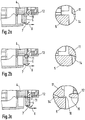
- the Figures 2a to 2e five different positions of the carbon brushes 5 are shown during the removal process of the holder 6 for the carbon brushes 5. For the sake of clarity, the Figures 2a to 2e only one carbon brush 5 is shown with the spring 7 depressing it without the holder 6.
- the armature plate 11 is provided on its side facing the carbon brushes 5 with a bevel 14, which slopes from the outer diameter of the armature plate 11 to the carbon brushes 5, the carbon brushes slide on this bevel 14 over the armature plate 11, the carbon brushes 5 are pushed radially outwards against the force of the spring 7.
- a bearing dome 12 which has a slightly larger diameter than the armature disk 11, does not constitute an obstacle to the movement of the holder 6 with the carbon brushes 5.
- the carbon brushes 5 slide namely over the bevel 15 of the bearing dome, whereby they act against the force the spring 7 are pushed outward until the carbon brushes 5 finally rest on the surface of the cylindrical wall 13 of the bearing dome 12.
- the holder 6 with the carbon brushes 5 arranged therein can be completely pulled off over the surface of the cylindrical wall 13 of the bearing dome 12.
- the bevels 14 and 15 on the armature plate 11 and on the bearing dome 12 can, as shown in the drawings, run in a straight line, but they can also have a curved course.
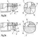
- the armature disk 11 is provided on its side facing the bearing dome 12 with a bevel 16 which enables the carbon brushes 5 to be pushed over the armature plate 11 onto the collector 4 without any obstacle from the bearing dome 12.
- This bevel 16 on the armature disk 11 is actually only required if the outer diameter of the bearing dome 12 is smaller than the outer diameter of the armature disk 11. Because only in this case, the armature disk 11 would slide on the bracket 6 with the carbon brushes 5 in the direction of the Collector 4 represent an obstacle.
- only one armature disk 11 or only one bearing dome 12 can be provided to protect the rotary bearing 3. Then only a bevel 14 or 15 on the armature plate 11 or on the bearing dome 12 is required.
- the wall 131 of the bearing dome 12 which is elongated in the axial direction and projects beyond the armature disk 11 also has the advantage that the gap between it and the armature disk 11 can be kept very small, which leads to increased tightness of the rotary bearing 3.
- the extension of the cylindrical wall 131 in the direction of the collector 4 causes cooling air to be conducted directly to the collector 4 and to the carbon brushes 5.
Description
Die vorliegende Erfindung betrifft einen Elektromotor mit einer Halterung für mindestens zwei Kohlebürsten, die mittels Federkraft in radialer Richtung auf die Mantelfläche eines zylinderförmigen, auf der Ankerwelle des Motors fixierten Kollektors gedrückt werden.The present invention relates to an electric motor with a holder for at least two carbon brushes, which are pressed in the radial direction by means of spring force onto the lateral surface of a cylindrical collector fixed on the armature shaft of the motor.
Mechanische kommutierte Elektromotoren haben üblicher Weise eine derartige Kohlebürsten-Kontaktierung, wie beispielsweise auch in der nicht vorveröffentlichten deutschen Patentanmeldung
Die genannte Aufgabe wird mit den Merkmalen des Anspruchs 1 dadurch gelöst, dass die Halterung mit den Kohlebürsten vom Kollektor in axialer Richtung der Ankerwelle über ein die Ankerwelle haltendes Drehlager hinweg abziehbar ist, und dass Mittel, welche das Drehlager gegen Eindringen von Schmutz abdecken, an ihrer der Halterung mit den Kohlebürsten zugewandten Seite mit einer oder mehreren so verlaufenden Schrägen versehen sind, dass darüber die Kohlebürsten beim Abziehen der Halterung hinweggleiten und dabei gegen die Federkraft radial nach außen geschoben werden.The stated object is achieved with the features of
Die Erfindung ermöglicht trotz Mitteln, welche das Drehlager gegen Eindringen von Schmutz (z.B. Abrieb der Kohlebürsten oder Bohrklein) schützen, eine einfache Demontage der Halterung mit den Kohlebürsten.Despite means which protect the pivot bearing against the ingress of dirt (eg abrasion of the carbon brushes or cuttings), the invention enables the holder with the carbon brushes to be easily removed.
Vorteilhafte Weiterbildungen der Erfindung gehen an den Unteransprüchen hervor.Advantageous developments of the invention emerge from the subclaims.
Zum Schutz des Drehlagers gegen Verschmutzung kann zwischen dem Drehlager und dem Kollektor eine Ankerscheibe angeordnet und/oder ein Lagerdom auf das Drehlager aufgesetzt werden. Ein ungehindertes Abziehen der Halterung mit den Kohlebürsten über das Drehlager hinweg wird dadurch ermöglicht, dass die dem Kollektor zugewandte Seite der Ankerscheibe und/oder des Lagerdomes mit einer geradlinigen oder gekrümmt verlaufenden Schräge versehen ist (sind).To protect the pivot bearing against contamination, an armature disk can be arranged between the pivot bearing and the collector and / or a bearing dome can be placed on the pivot bearing. Unhindered removal of the holder with the carbon brushes over the pivot bearing is made possible by the fact that the side of the armature disk and / or the bearing dome facing the collector is (are) provided with a straight or curved slope.
Anhand zweier in der Zeichnung dargestellter Ausführungsbeispiele wird nachfolgend die Erfindung näher erläutert. Es zeigen:
-
Figur 1 -
Figuren 2a bis 2e verschiedene Stellungen einer Kohlebürste beim Abziehen der Halterung für die Kohlebürsten von der Ankerwelle des Motors und -
Figur 3
-
Figure 1 a partial longitudinal section through an electric motor with a carbon brush holder arranged on its collector and means of a first embodiment for protecting the armature shaft pivot bearing against contamination. -
Figures 2a to 2e different positions of a carbon brush when removing the holder for the carbon brushes from the armature shaft of the motor and -
Figure 3 a partial longitudinal section through an electric motor with a carbon brush holder arranged on its collector and means of a second embodiment for protecting the armature shaft pivot bearing against contamination.
In der
Zwischen dem Kollektor 4 und dem Drehlager 3 ist auf der Ankerwelle 2 eine Ankerscheibe 11 angeordnet. Diese Ankerscheibe 11 dient dazu, das Drehlager 3 für die Ankerwelle 2 gegen das Eindringen von Abrieb der Kohlebürsten 5 und auch von Partikeln (z.B. Bohrstaub, Bohrklein), die beim Arbeitsvorgang einer Elektrowerkzeugmaschine angesaugt werden, zu schützen. Diese Ankerscheibe 11 hat einen größeren Durchmesser als der Kollektor 4 und ragt deshalb in radialer Richtung über den Kollektor 4 hinaus.An
In der Regel ist das Drehlager 3 eines Motors von einem Lagerdom 12 abgedeckt. Der Lagerdom 12 ist ein mit dem Gehäuse 8 in Verbindung stehendes kappenartiges Gebilde, welches das Drehlager 3 und die darin gelagerte Ankerwelle 2 an der dem Kollektor 4 abgewandten Stirnseite abdeckt und mit einer vorzugsweise abgeflachten, zylinderförmigen Wandung 13 das Drehlager 3 koaxial umschließt.As a rule, the rotary bearing 3 of an engine is covered by a bearing
Wie bereits vorangehend beschrieben, ist die Halterung 6 mit den Kohlebürsten 5 am Gehäuse 8 lösbar befestigt. Soll die Halterung 6 für einen Kohlebürstenwechsel vom Motor entfernt werden, wird das Rastelement 9 der Halterung 6 gelöst und die Halterung in axialer Richtung (Pfeilrichtung X) der Ankerwelle 2 vom Kollektor 4 abgezogen. In den
Gemäß der Darstellung in
Die in den
Damit auch das Aufschieben der Halterung 6 mit den Kohlebürsten 5 über die Ankerscheibe 11 hinweg bis auf den Kollektor 4 ohne Hindernis erfolgen kann, ist die Ankerscheibe 11 an ihrer dem Lagerdom 12 zugewandten Seite mit einer Schräge 16 versehen, welche es den Kohlebürsten 5 ermöglicht, ohne Hindernis vom Lagerdom 12 aus über die Ankerscheibe 11 hinweg auf den Kollektor 4 geschoben zu werden. Diese Schräge 16 an der Ankerscheibe 11 ist eigentlich nur dann erforderlich, wenn der Außendurchmesser des Lagerdoms 12 kleiner ist als der Außendurchmesser der Ankerscheibe 11. Denn nur für diesen Fall würde die Ankerscheibe 11 beim Aufschieben der Halterung 6 mit den Kohlebürsten 5 in Richtung auf den Kollektor 4 ein Hindernis darstellen.So that the
Abweichend von dem zuvor beschriebenen Ausführungsbeispiel kann zum Schutz des Drehlagers 3 nur eine Ankerscheibe 11 oder nur ein Lagerdom 12 vorgesehen werden. Dann ist auch nur eine Schräge 14 oder 15 an der Ankerscheibe 11 oder an dem Lagerdom 12 erforderlich.In a departure from the exemplary embodiment described above, only one
Das in der
Die in axialer Richtung verlängerte, über die Ankerscheibe 11 hinausragende Wandung 131 des Lagerdoms 12 hat außerdem den Vorteil, dass der Spalt zwischen ihr und der Ankerscheibe 11 sehr klein gehalten werden kann, was zu einer erhöhten Dichtigkeit des Drehlagers 3 führt. Die Verlängerung der zylindrischen Wandung 131 in Richtung des Kollektors 4 bewirkt, dass Kühlluft direkt zum Kollektor 4 und zu den Kohlebürsten 5 geleitet wird.The
Claims (6)
- Electric motor with a holder (6) for at least two carbon brushes (5) which are pressed by means of spring force in the radial direction onto the lateral face of a cylindrical collector (4) which is secured to the armature shaft (2) of the motor, wherein the holder (6) can be pulled off with the carbon brushes (5) from the collector (4) in the axial direction of the armature shaft (2) by means of a rotary bearing (3) which holds the armature shaft (2), characterized
in that means (11, 12) which cover the rotary bearing (3) to prevent the ingress of dirt are provided, on its side facing the holder (6) with the carbon brushes (5), with one or more slopes (14, 15) which extend in such a way that when the holder (6) is pulled off the carbon brushes (5) slide over said slopes (14, 15) and in the process are pushed radially outwards counter to the spring force. - Electric motor according to Claim 1, characterized in that an armature disc (11) is arranged on the armature shaft (2), between the collector (4) and the rotary bearing (3), and in that the end of the armature disc (11) which projects beyond the collector (4) in the radial direction is provided with a slope (14) over which the carbon brushes (5) slide when the holder (6) is pulled off, and in the process they are pushed radially outwards counter to the spring force.
- Electric motor according to Claim 1, characterized in that the rotary bearing (3) is covered by a bearing spike (12) which is provided, on its end side facing the holder (6) for the carbon brushes (5), with a slope (15) over which the carbon brushes (5) slide when the holder (6) is pulled off, and in the process said carbon brushes (5) are pushed radially outwards counter to the spring force.
- Electric motor according to Claim 1, characterized in that an armature disc (11) is arranged on the armature shaft (2), between the collector (4) and the rotary bearing (3), in that the rotary bearing (3) is covered by a bearing stud (12) which projects beyond the armature disc (11) in the direction of the collector (4), and in that the bearing stud (12) is provided, on its end side facing the holder (6) for the carbon brushes (5), with a slope (15) over which the carbon brushes (5) slide when the holder (6) is pulled off, and in the process they are pushed radially outward counter to the spring force.
- Electric motor according to one of Claims 2, 3 or 4, characterized in that the slope (14, 15) has a linear extent.
- Electric motor according to one of Claims 2, 3 or 4, characterized in that the slope (14, 15) has a curved extent.
Applications Claiming Priority (3)
| Application Number | Priority Date | Filing Date | Title |
|---|---|---|---|
| DE10228493A DE10228493A1 (en) | 2002-06-26 | 2002-06-26 | Electric motor with a holder for at least two carbon brushes |
| DE10228493 | 2002-06-26 | ||
| PCT/DE2003/001761 WO2004004094A1 (en) | 2002-06-26 | 2003-05-30 | Electric motor with a housing for at least two carbon brushes |
Publications (2)
| Publication Number | Publication Date |
|---|---|
| EP1520334A1 EP1520334A1 (en) | 2005-04-06 |
| EP1520334B1 true EP1520334B1 (en) | 2020-02-19 |
Family
ID=29723463
Family Applications (1)
| Application Number | Title | Priority Date | Filing Date |
|---|---|---|---|
| EP03761407.0A Expired - Lifetime EP1520334B1 (en) | 2002-06-26 | 2003-05-30 | Electric motor with a brush holder of at least two carbon brushes |
Country Status (5)
| Country | Link |
|---|---|
| US (1) | US7518281B2 (en) |
| EP (1) | EP1520334B1 (en) |
| CN (1) | CN100367632C (en) |
| DE (1) | DE10228493A1 (en) |
| WO (1) | WO2004004094A1 (en) |
Families Citing this family (2)
| Publication number | Priority date | Publication date | Assignee | Title |
|---|---|---|---|---|
| DE102008041717A1 (en) * | 2008-08-29 | 2010-03-04 | Robert Bosch Gmbh | Hand tool with brush motor |
| DE102010021506B4 (en) * | 2010-05-26 | 2012-02-23 | Atlanta-Elektrosysteme Gmbh | brush bridge |
Family Cites Families (5)
| Publication number | Priority date | Publication date | Assignee | Title |
|---|---|---|---|---|
| JPS5837784B2 (en) * | 1978-11-16 | 1983-08-18 | 株式会社日立製作所 | Brush holding device for rotating electric machines |
| US4293789A (en) * | 1979-09-10 | 1981-10-06 | General Motors Corporation | Dynamoelectric machine brush rigging |
| JPH058787Y2 (en) * | 1989-05-15 | 1993-03-04 | ||
| FR2725322B1 (en) * | 1994-10-04 | 1996-11-08 | Valeo Systemes Dessuyage | ROTATING ELECTRICAL MACHINE WITH MANIFOLD, IN PARTICULAR DIRECT CURRENT ELECTRIC MOTOR |
| DE10153574B4 (en) | 2001-10-30 | 2009-01-02 | Robert Bosch Gmbh | electric machine |
-
2002
- 2002-06-26 DE DE10228493A patent/DE10228493A1/en not_active Withdrawn
-
2003
- 2003-05-30 US US10/511,286 patent/US7518281B2/en not_active Expired - Fee Related
- 2003-05-30 EP EP03761407.0A patent/EP1520334B1/en not_active Expired - Lifetime
- 2003-05-30 WO PCT/DE2003/001761 patent/WO2004004094A1/en not_active Application Discontinuation
- 2003-05-30 CN CNB038152169A patent/CN100367632C/en not_active Expired - Fee Related
Non-Patent Citations (1)
| Title |
|---|
| None * |
Also Published As
| Publication number | Publication date |
|---|---|
| EP1520334A1 (en) | 2005-04-06 |
| US7518281B2 (en) | 2009-04-14 |
| CN1666402A (en) | 2005-09-07 |
| CN100367632C (en) | 2008-02-06 |
| WO2004004094A1 (en) | 2004-01-08 |
| US20060087196A1 (en) | 2006-04-27 |
| DE10228493A1 (en) | 2004-01-15 |
Similar Documents
| Publication | Publication Date | Title |
|---|---|---|
| EP3287061B1 (en) | Hand-held cleaning and care device | |
| EP2152475A1 (en) | Adapter for a motor-driven machine tool with tool to be rotatably driven | |
| DE102013219186A1 (en) | Electric machine and connection unit for electric machine. | |
| DE2632184C2 (en) | Brush-carrying plug insert for an electric motor | |
| EP1742332B1 (en) | Adjusting device for reversing of the direction of rotation | |
| DE102014113517B4 (en) | Self-cleaning brush system for cleaning surfaces | |
| EP1096649B1 (en) | Drilling apparatus | |
| EP1520334B1 (en) | Electric motor with a brush holder of at least two carbon brushes | |
| EP1279363B1 (en) | Apparatus for fixing a brush body to the housing of a floor cleaning device | |
| DE102006032189A1 (en) | Spindle unit for a multi-spindle drilling unit | |
| WO2007101449A1 (en) | Apparatus for winding an electrical cable | |
| DE19906268A1 (en) | Arrangement for electrically locking steering shaft of steering device of motor vehicle, has housing containing motor which displaces blocking element connected to adapter that absorbs force if shaft is violently twisted | |
| EP2201652B1 (en) | Commutation device and electric machine | |
| EP0699500A1 (en) | Apparatus for the mechanical removal of deposits on welding electrodes | |
| EP3668683B1 (en) | Machine tool with electrically isolated fixing element | |
| EP3315231A1 (en) | Worktool for machining a tube end | |
| DE202005006571U1 (en) | Electrically motorised drive for beds, chairs and other furniture has two part housing divided at right angle to centre longitudinal axis of spindle with a connecting element on first housing part and guide tube for spindle on second part | |
| EP3771511A1 (en) | Manually operated cutting machine and tool for a manually operated cutting machine | |
| EP3578317B1 (en) | Handheld machine tool | |
| LU101351B1 (en) | Tubular motor set | |
| WO2021122808A1 (en) | Linear drive with easily installable electric motor | |
| EP2948345A1 (en) | Driving device for a wiper arm | |
| EP2268457B1 (en) | Connecting device/housing combination for a machine tool, in particular for a handheld machine tool | |
| DE102019212280A1 (en) | Hand tool with electric drive | |
| EP0456161A2 (en) | Switch lock, in particular for data processing apparatus |
Legal Events
| Date | Code | Title | Description |
|---|---|---|---|
| PUAI | Public reference made under article 153(3) epc to a published international application that has entered the european phase |
Free format text: ORIGINAL CODE: 0009012 |
|
| 17P | Request for examination filed |
Effective date: 20050126 |
|
| AK | Designated contracting states |
Kind code of ref document: A1 Designated state(s): AT BE BG CH CY CZ DE DK EE ES FI FR GB GR HU IE IT LI LU MC NL PT RO SE SI SK TR |
|
| RBV | Designated contracting states (corrected) |
Designated state(s): CH DE GB LI |
|
| 17Q | First examination report despatched |
Effective date: 20110704 |
|
| STAA | Information on the status of an ep patent application or granted ep patent |
Free format text: STATUS: EXAMINATION IS IN PROGRESS |
|
| GRAP | Despatch of communication of intention to grant a patent |
Free format text: ORIGINAL CODE: EPIDOSNIGR1 |
|
| STAA | Information on the status of an ep patent application or granted ep patent |
Free format text: STATUS: GRANT OF PATENT IS INTENDED |
|
| INTG | Intention to grant announced |
Effective date: 20191015 |
|
| GRAS | Grant fee paid |
Free format text: ORIGINAL CODE: EPIDOSNIGR3 |
|
| GRAA | (expected) grant |
Free format text: ORIGINAL CODE: 0009210 |
|
| STAA | Information on the status of an ep patent application or granted ep patent |
Free format text: STATUS: THE PATENT HAS BEEN GRANTED |
|
| AK | Designated contracting states |
Kind code of ref document: B1 Designated state(s): CH DE GB LI |
|
| REG | Reference to a national code |
Ref country code: GB Ref legal event code: FG4D Free format text: NOT ENGLISH |
|
| REG | Reference to a national code |
Ref country code: CH Ref legal event code: EP |
|
| REG | Reference to a national code |
Ref country code: DE Ref legal event code: R096 Ref document number: 50315876 Country of ref document: DE |
|
| RAP2 | Party data changed (patent owner data changed or rights of a patent transferred) |
Owner name: ROBERT BOSCH GMBH |
|
| REG | Reference to a national code |
Ref country code: DE Ref legal event code: R097 Ref document number: 50315876 Country of ref document: DE |
|
| REG | Reference to a national code |
Ref country code: DE Ref legal event code: R119 Ref document number: 50315876 Country of ref document: DE |
|
| PLBE | No opposition filed within time limit |
Free format text: ORIGINAL CODE: 0009261 |
|
| STAA | Information on the status of an ep patent application or granted ep patent |
Free format text: STATUS: NO OPPOSITION FILED WITHIN TIME LIMIT |
|
| 26N | No opposition filed |
Effective date: 20201120 |
|
| PG25 | Lapsed in a contracting state [announced via postgrant information from national office to epo] |
Ref country code: CH Free format text: LAPSE BECAUSE OF NON-PAYMENT OF DUE FEES Effective date: 20200531 Ref country code: LI Free format text: LAPSE BECAUSE OF NON-PAYMENT OF DUE FEES Effective date: 20200531 |
|
| GBPC | Gb: european patent ceased through non-payment of renewal fee |
Effective date: 20200530 |
|
| PG25 | Lapsed in a contracting state [announced via postgrant information from national office to epo] |
Ref country code: GB Free format text: LAPSE BECAUSE OF NON-PAYMENT OF DUE FEES Effective date: 20200530 |
|
| PG25 | Lapsed in a contracting state [announced via postgrant information from national office to epo] |
Ref country code: DE Free format text: LAPSE BECAUSE OF NON-PAYMENT OF DUE FEES Effective date: 20201201 |