EP1520207B1 - Procede et appareil de balayage de la ligne de visee de la camera dans un systeme de camera a zoom continu - Google Patents
Procede et appareil de balayage de la ligne de visee de la camera dans un systeme de camera a zoom continu Download PDFInfo
- Publication number
- EP1520207B1 EP1520207B1 EP03761857A EP03761857A EP1520207B1 EP 1520207 B1 EP1520207 B1 EP 1520207B1 EP 03761857 A EP03761857 A EP 03761857A EP 03761857 A EP03761857 A EP 03761857A EP 1520207 B1 EP1520207 B1 EP 1520207B1
- Authority
- EP
- European Patent Office
- Prior art keywords
- fov
- scan
- los
- operator
- width
- Prior art date
- Legal status (The legal status is an assumption and is not a legal conclusion. Google has not performed a legal analysis and makes no representation as to the accuracy of the status listed.)
- Expired - Lifetime
Links
- 238000000034 method Methods 0.000 title claims description 30
- 230000001419 dependent effect Effects 0.000 claims description 18
- 230000006870 function Effects 0.000 claims description 15
- 230000008569 process Effects 0.000 claims description 13
- 230000035945 sensitivity Effects 0.000 claims description 13
- 230000007246 mechanism Effects 0.000 claims description 11
- 230000010354 integration Effects 0.000 claims description 10
- 230000015654 memory Effects 0.000 claims description 9
- 230000008859 change Effects 0.000 claims description 8
- 230000006641 stabilisation Effects 0.000 claims description 6
- 238000011105 stabilization Methods 0.000 claims description 6
- 239000000470 constituent Substances 0.000 claims description 4
- 101000740382 Homo sapiens Sciellin Proteins 0.000 claims description 3
- 102100037235 Sciellin Human genes 0.000 claims description 3
- 238000001514 detection method Methods 0.000 claims description 3
- 230000015556 catabolic process Effects 0.000 description 6
- 238000006731 degradation reaction Methods 0.000 description 6
- 238000013461 design Methods 0.000 description 6
- 238000004458 analytical method Methods 0.000 description 4
- 238000010586 diagram Methods 0.000 description 3
- 238000003384 imaging method Methods 0.000 description 3
- 238000012360 testing method Methods 0.000 description 3
- 241000721701 Lynx Species 0.000 description 2
- 238000011156 evaluation Methods 0.000 description 2
- 230000004044 response Effects 0.000 description 2
- 230000008685 targeting Effects 0.000 description 2
- 238000002834 transmittance Methods 0.000 description 2
- 238000013459 approach Methods 0.000 description 1
- 210000004556 brain Anatomy 0.000 description 1
- 210000004720 cerebrum Anatomy 0.000 description 1
- 230000001939 inductive effect Effects 0.000 description 1
- 210000001747 pupil Anatomy 0.000 description 1
- 238000002310 reflectometry Methods 0.000 description 1
- 238000004904 shortening Methods 0.000 description 1
- 239000007787 solid Substances 0.000 description 1
- 230000003595 spectral effect Effects 0.000 description 1
- 230000000007 visual effect Effects 0.000 description 1
Images


Classifications
-
- G—PHYSICS
- G01—MEASURING; TESTING
- G01C—MEASURING DISTANCES, LEVELS OR BEARINGS; SURVEYING; NAVIGATION; GYROSCOPIC INSTRUMENTS; PHOTOGRAMMETRY OR VIDEOGRAMMETRY
- G01C11/00—Photogrammetry or videogrammetry, e.g. stereogrammetry; Photographic surveying
- G01C11/02—Picture taking arrangements specially adapted for photogrammetry or photographic surveying, e.g. controlling overlapping of pictures
- G01C11/025—Picture taking arrangements specially adapted for photogrammetry or photographic surveying, e.g. controlling overlapping of pictures by scanning the object
-
- G—PHYSICS
- G03—PHOTOGRAPHY; CINEMATOGRAPHY; ANALOGOUS TECHNIQUES USING WAVES OTHER THAN OPTICAL WAVES; ELECTROGRAPHY; HOLOGRAPHY
- G03B—APPARATUS OR ARRANGEMENTS FOR TAKING PHOTOGRAPHS OR FOR PROJECTING OR VIEWING THEM; APPARATUS OR ARRANGEMENTS EMPLOYING ANALOGOUS TECHNIQUES USING WAVES OTHER THAN OPTICAL WAVES; ACCESSORIES THEREFOR
- G03B41/00—Special techniques not covered by groups G03B31/00 - G03B39/00; Apparatus therefor
-
- H—ELECTRICITY
- H04—ELECTRIC COMMUNICATION TECHNIQUE
- H04N—PICTORIAL COMMUNICATION, e.g. TELEVISION
- H04N23/00—Cameras or camera modules comprising electronic image sensors; Control thereof
- H04N23/20—Cameras or camera modules comprising electronic image sensors; Control thereof for generating image signals from infrared radiation only
Definitions
- This invention relates to the method and apparatus for an automatic FOV(field of view) dependent LOS(line of sight) scanning in a turret aided continuous zoom camera system.
- the step zoom optics (at most 2 to 3 steps) has been widely adopted in a turret aided camera system for reconnaissance and surveillance mission.
- an operator empirically and manually determined the LOS scan condition (the scan width and rate) at each FOV.
- the manual LOS scanning method since the functional relationship of the scan condition and the FOV nor its relevant parametric calibration is seriously required (hereafter this is called the manual LOS scanning method while the current invention is said an automatic one in contrast to the manual one).
- the manual LOS scanning apparatus may be used without big inconveniences.
- GB 2 273 413 A discloses a system and method for performing long range, sector scan panoramic electro-optical reconnaissance of a scene at increased aircraft velocities.
- the scene is scanned at a non-linear scan velocity.
- the image is converted into an electronic signal, which is transmitted to a ground station where it is processed to provide visual image data that represents the scene. Distortion inducted into this data as a result of the non-linear scan velocity is removed to provide a distortion free final image.
- EP 0 399 180 A2 discloses a method and apparatus for search and tracking multiple targets in an object space.
- the apparatus includes a targeting FLIR (forward looking infrared) imaging unit which is operable to generate an output in response to the observations of the multiple targets.
- the apparatus also includes an infrared search and tracking electronics unit allowing detection and tracking of the multiple targets in response to the output of the targeting FLIR imaging unit.
- FLIR forward looking infrared
- US 5,663 825 A discloses a method and apparatus for holding a line of sight (LOS) in a scanning imaging system with continuous relative movement between the field of view (FOV) of the system and the image plane.
- the apparatus includes a scanning mechanism such as a gimbal and a descan mechanism.
- the descan mechanism descans the image by inducing a relative movement which is opposite to the direction of movement of the scanning mechanism.
- LOS line of sight
- FOV field of view
- EP 0 609 162 A discloses an airborne obstacle collision avoidance apparatus.
- the apparatus includes an object sensor for sensing objects within a field of view (FOV) of the aircraft.
- the apparatus further includes an aircraft navigation system for navigating the aircraft through space.
- a signal processor coupled to the object sensor and the aircraft navigation system generates map data of the objects within the FOV and dynamically changes the map data as the aircraft moves through space in order to determine a probability that the aircraft is on a collision course with respect to each sensed object.
- the AZ LOS (EL LOS ) are the initial the azimuth (elevation) angle of LOS direction.
- the n(t e ) is expressed as C'/t e with constant C')
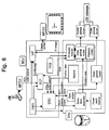
- an automatic LOS scanning apparatus comprises a turret sensor unit (TSU) including the sensor with variable zoom optics, the mechanical structures and stabilization driver, the multifunctional display unit (MFDU) displaying the image and symbology; the multifunctional control unit (MFCU) interfacing whole camera system with an operator; a system electronics unit (SEU) including a system control processor (SCP), a digital servo controller (DSC), a video interface board (VIF) and a power modules (PWR) wherein the SCP is connected to the other modules, receiving and transmitting all the data in-between the constituent modules and governing the whole camera system, the DSC controls the LOS with the FOV data commanded from the MFCU via the SCP, the VIF generates the symbology related to the sensor data and the PWR supplies all the modules with power, wherein the SCP and DSC include a memory storing the program for the scan process algorithm to determine the scan condition according to the following relations:
- Scanning the camera LOS implies the sweep of the LOS on the azimuth plane with reference to its initial position like the swing of a simple pendulum (see Fig. 1 a) .
- the current invention of an automatic FOV dependent LOS scanning method is applicable to any kinds of a turret aided zoom camera system for reconnaissance and surveillance. Its design approach and apparatus implementation are described in the following.
- the representative quantities determining the image quality are SNR and MTF.
- the SNR is related to the radiometric performance and the MTF the spatial resolution in the spatial frequency ( ⁇ ) domain.
- SNR(0) is the system SNR for uniform background, MTF tot the system MTF including all the contributions such as the optics MTF(MTF Optics ), the motional MTF (MTF Motion ) and others (MTF Others ) and so on.
- the incident beam (L 1 : spectral radiance) on the optics, reflected from the target (reflectance: ⁇ ) transmits through the atmosphere and is then converted into the electronic signal by the detector
- the signal (S V ) is proportional to the incident beam intensity, atmospheric transmittance ( ⁇ a ), the solid angle ( ⁇ ) subtended to the detector pixel, the entrance pupil of the optics (D), the detector responsivity (R) and the optics transmittance ( ⁇ o ).
- p, f and ⁇ are the pixel size, the focal length and the light wave length, respectively.
- the physics of the equations 2 to 6 means that the SNR for the camera with constant f/D remains constant irrespectively of the change in the focal length whatever the f may be changed. Namely, the image contrast for such camera is determined only by the MTF performance.
- MRT the barely measurable ⁇ T through the monitor
- MRT the minimum resolvable temperature difference
- FOR ⁇ 180°
- WFOV 40°
- the equation 8 means that the scan width is proportional to the FOV (see Fig. 2 ).
- v sc and t are respectively the scan speed of the focal length vector and the relevant time duration.
- the T y and V sc are in turn the y-component of ground plane pixel and the scan speed of LOS (see Fig. 3a ).
- the scan speed of the camera LOS V sc
- the integration time t intg can be converted into the eye integration time t e from the engineering viewpoint.
- the equation 10 means that the scan rate is almost linearly proportional to the FOV (see Fig. 4 ).
- the C 0 includes all the constants(c, n', l y , p, t e ) in the equation 10.
- the initial reference positions may be set by the same values as those in the previous mode or by the command manually made with the joystick even in the scan mode.
- the scan motion can be implemented by the servo controller in function of sine or cosine, like the following equation.
- ⁇ scan A ⁇ sin ⁇ ⁇ t + ⁇
- the reference positions of the scan may be set by the elevation and azimuth angles in the previous mode or by the command manually made with the joystick even in the scan mode.
- the function of tan(FOV/2) is linearly proportional to the FOV in the range of FOV/2 ⁇ 20°, and the scan period is almost constant in the whole FOV range accordingly (see Fig. 5 ).
- the present invention is explained by introducing the HFLIR (heli-borne FLIR system) as an example, but can be applied to any kinds of the turret aided zoom camera system whether it uses visible or IR beams.
- HFLIR heli-borne FLIR system
- Fig. 1 a is the perspective view showing how the LOS of a camera (called HFLIR) scans for scout using helicopter and Fig. 1b is the side view of a TFU mounted onto the nose of a LYNX helicopter.
- the TFU changes its LOS direction by rotating the turret unit around both the elevation and azimuth angle axes.
- HFLIR shows the all the components in HFLIR where this invention is actually adopted.
- HFLIR consists of four different line replaceable units (LRUs) such as the multi-functional display unit (MFDU), the multi-functional control unit (MFCU), the system electronics unit (SEU) and the turret FLIR unit (TFU).
- LRUs line replaceable units
- MFDU multi-functional display unit
- MFCU multi-functional control unit
- SEU system electronics unit
- TFU turret FLIR unit
- the MFDU displays the IR image and all the symbology including the character and the numerical values.
- the MFCU interfaces the operator with the whole HFLIR system.
- the SEU has five different boards such as the system controls processor (SCP), the digital servo controller (DSC), the video interface board (VIF), the power board (PWR) and the FLIR electronics power board (FEB).
- SCP system controls processor
- DSC digital servo controller
- VIF video interface board
- PWR power board
- FEB FLIR electronics power board
- the SCP is connected to all the other modules, receiving and transmitting all the data in-between the constituent modules and governing and managing the HFLIR, like a cerebrum in the human brain.
- the DSC controls the LOS of TFU with the FOV data received from the SCP and the VIF generates the symbology (the FOV, the LOS direction, etc.) received from the SCP and display them together with the IR image coming from the IR sensor module.
- the PWR and FEB supply all the modules with power.
- the TFU consists of the IR sensor module, the mechanical structures and stabilization driver.
- the mechanical structure includes the 4-axes inner and outer gimbals. The inner and outer gimbals are rotated with the help of the motor around the elevation and azimuth axes.
- the potentiometer, the gyroscope and the motor are mounted onto the inner gimbal to which the outer one with the resolver is slaved.
- the stabilization driver consists of the servo amplifier module and the power pack module (see Fig. 9 ).
- Fig. 6 The functional relationship of all the modules is shown in Fig. 6 , which can be explained as follows. If the operator gives a command of the LOS change by the MFCU, this command is transmitted to the DSC via the SCP, giving rise to a gyro-driving signal. This signal is input to the gyroscope in the TFU and its output signal is fed back to the DSC to generate a command which is then amplified by the servo-amplifier module enough for driving the inner gimbal motor.
- the potentiometer is used to measure the difference in the position between the inner and outer gimbals. The measured position difference is transmitted to the DSC that generates the signal as much as the rotation of the inner gimbal.
- This signal is also amplified by the servo-amplifier module and is then fed to derive the outer gimbal motor.
- the resolver measures the position change of the outer gimbal and transmits it to the DSC. Using these functions, the operator can change the LOS of the TFU.
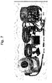
- Fig. 7 shows the fabricated HFLIR, which has been mounted on the three different kinds of helicopter such as Super-LYNX, UH-60 and HH-47.
- Fig. 8 shows the pictures for the SEU and its constituent electronic boards, where the SCP and the DSC are shown in more detail.
- Fig. 9 depicts the TFU.
- the scan process can be made on the basis of the functional block diagram shown in Fig. 6 , which is done as follows.
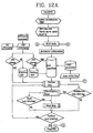
- Fig. 12 shows the flow chart made according to the scan process mentioned above.
- the scan process automatically determines the scan width and rate. Since the operator may generally prefer the sensitivity of the scan condition to the FOV proper to himself, he can calibrate it before taking off for scout. Thus the calibration mode is necessarily made for the operator to choose the sensitivity suitable for himself.
- the scan parameter ⁇ SCAN PARAMETER> has two parameters of WIDTH and RATE.
- the WIDTH and RATE correspond to the observation width constant (m) and the eye integration time (t e ), respectively. These two correspondences have the proportional relationship, which is also coded and stored in the flash memory on the SCP and is hidden implicitly.
- the operator can see just the WIDTH and RATE instead of the m and t e .
- the calibration method for HFLIR is as follows.
- the operator generates the cursor * in the calibration page by pushing the b key in the MFCU and move the * to the e WIDTH or f RATE by pushing ⁇ key up or downward.
- the operator executes the item with cursor by pushing d key of the MFCU to make it twinkling.
- d key of the MFCU to make it twinkling.
- he can select a certain value in the rage of +1.4 ⁇ +0.8 with the b key.
- pushing d key stops its twinkling, which means storing the selected scan parameter.
- Table 1 the relation of WIDTH and m as well as that of RATE and t e is summarized in table 1.
- the integrated circuits (ICs) expressed by circles are the flash memory of EPROM function.
- the open area is programmed in the flash memory on the SCP ( Fig. 8a ) and the shaded area is in the flash memory on the DSC ( Fig. 8b ).
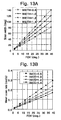
- Fig. 13a and 13b respectively shows the scan width and mean scan rate measured as a function of the FOV, by identifying the IR image with good quality displayed on the MFDU.
- the datum points for the scan width were measured proportional to the FOV, as the design (solid line) of the equation 8. The data are proved to be consistent with the design within the experimental error. The measured mean scan rate also turned out to comply with the design (solid line) of the equation 10.
- the scan period is measured to be almost constant irrespectively of the FOV, when no serious degradation in the image quality is observed.
- the captured images are shown in Fig. 14 . This is the fact only for the zoom camera with constant f-number, as can be seen from the theory in section B.
- test and evaluation results for this invention have been checked from the viewpoints of the scout mission fulfillment, the functional and operational convenience and the operational efficiency.
- the user can very easily adjust the FOV of the continuous zoom camera with the MFCU.
- the scan condition (the scan width and rate) is automatically set on the basis of the selected FOV, resulting in the FOV dependent scanning is implemented.
- the operator the pilot
- the operator can easily fulfill the scout mission without any inconvenience, which would be caused by the application of manual LOS scan method to the continuous zoom camera where the scan condition must be reset at each zoom step.
- the operator can select the FOV sensitivity of the scan condition proper to himself by changing the scan parameters though the calibration mode.
- the operational efficiency for scout mission is remarkably improved by applying this invention to HFLIR.
- This invention is applicable to all the turret aided zoom camera systems installed where the surveillance and reconnaissance mission is required: the public place like the parking place, the bank office and the park as well as the aircraft (the fixed or rotary typed flight, unmanned air vehicle) and the naval vessel (war or cruise ships) and so on.
Landscapes
- Engineering & Computer Science (AREA)
- Multimedia (AREA)
- Signal Processing (AREA)
- Physics & Mathematics (AREA)
- General Physics & Mathematics (AREA)
- Radar, Positioning & Navigation (AREA)
- Remote Sensing (AREA)
- Closed-Circuit Television Systems (AREA)
- Length Measuring Devices By Optical Means (AREA)
- Eye Examination Apparatus (AREA)
- Optical Radar Systems And Details Thereof (AREA)
- Studio Devices (AREA)
Claims (10)
- Un procédé de balayage de la ligne de visée (LOS) dépendante du champ de vision (FOV) dans une caméra à tourelle à zoom continu à ouverture-f constante (f/D), dans lequel on fait varier de manière continue le champ de vision FOV, dans lequel
la largeur de balayage est dépendante du champ de vision FOV suivant la relation ci-après :
dans laquelle Ws est la largeur de balayage et m est la constate de largeur d'observation;
le taux moyen de balayage de la ligne de visée LOS pour une demi période étant déterminée en fonction du champ de vision FOV suivant la relation ci-après :
dans laquelle ΩS et te sont respectivement le taux de balayage et le temps d'intégration de l'oeil et C0 et C1 sont des constantes proportionnelles;
les deux equations ci-dessus permettant d'exprimer comme suit le mécanisme de balayage de la ligne de visée (LOS) dépendant du champ de vision FOV:
dans lequel θSCAZ et θSCEL correspondent respectivement aux angles d'azimut et d'élévation du vecteur LOS, AZLOS et ELLos correspondent à la position de référence initiale de la ligne de visée LOS dans les angles azimutal et d'élévation et n(te) est exprimé par C'/te avec la constante C'. - Le procédé suivant la revendication 1, dans lequel m varie de 2.0 à 4.0 de telle manière que l'opérateur peut régler la sensibilité de la largeur de balayage au champ de vision FOV par une sélection au sein de cette gamme.
- Le procédé suivant la revendication 1, dans lequel te varie de 0.06 à 0.11 de telle manière que l'opérateur peut régler la sensibilité de la largeur de balayage au champ de vision FOV par une sélection au sein de cette gamme.
- Le procédé suivant la revendication 1, dans lequel la période de balayage de la ligne de visée LOS de la caméra est presque constante et indépendante du champ de vision FOV.
- Un dispositif de balayage de la ligne de visée (LOS) dépendante du champ de vision (FOV) pour un système de caméra à zoom continu comportant :- un module de capture à tourelle (TSU) comportant un capteur doté d'optiques ayant des zoom variable, de structures mécaniques et d'un moteur de stabilisation;- une unité d'affichage multifonctions (MFDU) pour l'affichage de l'image et de signes symboliques ;- une unité de commande multifonctions (MFCU) pour l'interfaçage du système de caméra avec un opérateur ;- une unité électronique système (SEU) comportant un processeur de commande de système (SCP), un contrôleur servo numérique (DSC), une carte d'interface vidéo (VIF) et des modules d'alimentation (PWR), dans lequel le SCP est connecté aux autres modules, pour la réception et pour la transmission de toutes les données entre les modules constitutifs et pour le pilotage de l'ensemble du système de caméra, le DCS étant organisé pour la commande de la ligne de visée LOS avec les données du champ de vision FOV commandées par le MFCU via le processeur de commande de système SCP, la carte d'interfaçage vidéo VIF étant organisée pour générer les signes symboliques relative aux données capturées et le PWR servant à alimenter en courant tous les modules ;dans lequel le SCP et le DSC comporte une mémoire pour le stockage du programme de l'algorithme de balayage commandant le balayage suivant les relations ci-après:
largeur de balayage =f1 (m, FOV); f1 étant une fonction monotone de FOV avec un paramètre m
le taux de balayage = f2 (te, FOV); f2 étant une fonction monotone de FOV avec un paramètre te,
dans lequel m est la constante de largeur d'observation et te le temps d'intégration de l'oeil;
et un procédé de calibrage étant également programme au sein de la même mémoire afin de permettre à l'opérateur de sélectionner la sensibilité du champ de vision FOV du balayage en lui permettant de modifier les paramètres. - Le dispositif selon la revendication 5, dans lequel la largeur de balayage est proportionnelle au champ de vision FOV sélectionné par l'opérateur suivant l'équation ci-après:

dans laquelle WS est la largeur de balayage et m est la constante de la distance d'observation. - Le dispositif selon la revendication 6, dans lequel m varie de 2.0 à 4.0 de telle manière que l'opérateur peut régler la sensibilité de la largeur de balayage au champ de vision FOV par une sélection au sein de cette gamme.
- Le dispositif selon la revendication 5, dans lequel le taux de balayage croît presque linéairement par rapport au champ de vision FOV sélectionné par l'opérateur suivant la relation ci-après:

dans laquelle ΩS et te sont respectivement le taux de balayage et le temps d'intégration de l'oeil et C0 et C1 sont des constantes proportionnelles. - Le dispositif selon la revendication 8, dans lequel te varie de 0.06 à 0.11 de telle manière que l'opérateur peut régler la sensibilité de la largeur de balayage au champ de vision FOV par une sélection au sein de cette gamme.
- Le dispositif suivant l'une quelconque des revendications 5 à 9, dans lequel le dispositif est appliqué à une camera zoom à tourelle caractérisée par une détection infrarouge (IR) ou visible.
Applications Claiming Priority (3)
| Application Number | Priority Date | Filing Date | Title |
|---|---|---|---|
| KR1020020036465A KR100377329B1 (en) | 2002-06-27 | 2002-06-27 | Automatic scan device and method with scan width and rate dependent on view field of zoom optical system |
| KR2002036465 | 2002-06-27 | ||
| PCT/KR2003/001263 WO2004003662A1 (fr) | 2002-06-27 | 2003-06-27 | Procede et appareil de balayage de la ligne de visee de la camera dans un systeme de camera a zoom continu |
Publications (3)
| Publication Number | Publication Date |
|---|---|
| EP1520207A1 EP1520207A1 (fr) | 2005-04-06 |
| EP1520207A4 EP1520207A4 (fr) | 2007-08-01 |
| EP1520207B1 true EP1520207B1 (fr) | 2008-12-10 |
Family
ID=29997394
Family Applications (1)
| Application Number | Title | Priority Date | Filing Date |
|---|---|---|---|
| EP03761857A Expired - Lifetime EP1520207B1 (fr) | 2002-06-27 | 2003-06-27 | Procede et appareil de balayage de la ligne de visee de la camera dans un systeme de camera a zoom continu |
Country Status (6)
| Country | Link |
|---|---|
| US (1) | US7468740B2 (fr) |
| EP (1) | EP1520207B1 (fr) |
| KR (1) | KR100377329B1 (fr) |
| DE (1) | DE60325217D1 (fr) |
| ES (1) | ES2319408T3 (fr) |
| WO (1) | WO2004003662A1 (fr) |
Families Citing this family (4)
| Publication number | Priority date | Publication date | Assignee | Title |
|---|---|---|---|---|
| US20080100711A1 (en) * | 2006-10-26 | 2008-05-01 | Wisted Jeffrey M | Integrated Multiple Imaging Device |
| US20120098971A1 (en) * | 2010-10-22 | 2012-04-26 | Flir Systems, Inc. | Infrared binocular system with dual diopter adjustment |
| US10531052B2 (en) | 2017-01-27 | 2020-01-07 | Live Earth Imaging Enterprises, L.L.C. | Real-time satellite imaging system |
| US11831988B2 (en) | 2021-08-09 | 2023-11-28 | Rockwell Collins, Inc. | Synthetic georeferenced wide-field of view imaging system |
Family Cites Families (8)
| Publication number | Priority date | Publication date | Assignee | Title |
|---|---|---|---|---|
| US4983837A (en) * | 1988-10-31 | 1991-01-08 | Texas Instruments Incorporated | Forward looking infrared imaging system |
| US5001650A (en) * | 1989-04-10 | 1991-03-19 | Hughes Aircraft Company | Method and apparatus for search and tracking |
| US5481479A (en) * | 1992-12-10 | 1996-01-02 | Loral Fairchild Corp. | Nonlinear scanning to optimize sector scan electro-optic reconnaissance system performance |
| IL104542A (en) | 1993-01-28 | 1996-05-14 | Israel State | Airborne obstacle collision avoidance apparatus |
| US5663825A (en) * | 1995-06-07 | 1997-09-02 | Martin Marietta Corporation | Stabilized step/stare scanning device |
| CA2250751C (fr) * | 1996-04-01 | 2002-03-12 | Lockheed Martin Corporation | Systeme optique combine laser/flir |
| FR2751761B1 (fr) * | 1996-07-24 | 1998-10-23 | Sfim Ind | Systeme d'observation ou de visee |
| US6271877B1 (en) * | 1999-06-25 | 2001-08-07 | Astrovision, Inc. | Direct broadcast imaging satellite system apparatus and method for providing real-time, continuous monitoring of earth from geostationary earth orbit |
-
2002
- 2002-06-27 KR KR1020020036465A patent/KR100377329B1/ko not_active Expired - Fee Related
-
2003
- 2003-06-27 ES ES03761857T patent/ES2319408T3/es not_active Expired - Lifetime
- 2003-06-27 US US10/519,351 patent/US7468740B2/en not_active Expired - Fee Related
- 2003-06-27 DE DE60325217T patent/DE60325217D1/de not_active Expired - Lifetime
- 2003-06-27 WO PCT/KR2003/001263 patent/WO2004003662A1/fr not_active Ceased
- 2003-06-27 EP EP03761857A patent/EP1520207B1/fr not_active Expired - Lifetime
Also Published As
| Publication number | Publication date |
|---|---|
| EP1520207A4 (fr) | 2007-08-01 |
| WO2004003662A1 (fr) | 2004-01-08 |
| EP1520207A1 (fr) | 2005-04-06 |
| KR100377329B1 (en) | 2003-03-26 |
| US20050231614A1 (en) | 2005-10-20 |
| US7468740B2 (en) | 2008-12-23 |
| ES2319408T3 (es) | 2009-05-07 |
| DE60325217D1 (de) | 2009-01-22 |
Similar Documents
| Publication | Publication Date | Title |
|---|---|---|
| EP2429858B1 (fr) | Système ladar flash | |
| DE69419102T2 (de) | Hindernissvermeidungssystem für Hubschrauber und Flugzeuge | |
| US20070247517A1 (en) | Method and apparatus for producing a fused image | |
| KR102151815B1 (ko) | 카메라 및 라이다 센서 융합을 이용한 객체 검출 방법 및 그를 위한 장치 | |
| US20110128162A1 (en) | System for the detection and the depiction of objects in the path of marine vessels | |
| JPH03213498A (ja) | 空中攻撃及び航行任務を補佐するオプトエレクトロニクスシステム | |
| CN108469618B (zh) | 测绘装置和用于测绘装置的旋转单元的旋转体 | |
| US7212938B2 (en) | Method of using a self-locking travel pattern to achieve calibration of remote sensors using conventionally collected data | |
| Walser | Development and calibration of an image assisted total station | |
| WO1999060335A1 (fr) | Appareil d'arpentage | |
| US20190120965A1 (en) | Method and system of digital light processing and light detection and ranging for guided autonomous vehicles | |
| JP2022149716A (ja) | 測量システム | |
| English et al. | TriDAR: A hybrid sensor for exploiting the complimentary nature of triangulation and LIDAR technologies | |
| JP3001866B1 (ja) | 飛行体を用いた測量方法及びその装置 | |
| Stann et al. | Integration and demonstration of MEMS-scanned LADAR for robotic navigation | |
| EP1520207B1 (fr) | Procede et appareil de balayage de la ligne de visee de la camera dans un systeme de camera a zoom continu | |
| EP3956631A1 (fr) | Détection agile de profondeur à l'aide de rideaux de lumière de triangulation | |
| Amzajerdian et al. | Utilization of 3D imaging flash lidar technology for autonomous safe landing on planetary bodies | |
| US11972586B2 (en) | Agile depth sensing using triangulation light curtains | |
| Bers et al. | Laser radar system for obstacle avoidance | |
| Seidel et al. | Novel approaches to helicopter obstacle warning | |
| Volkmer et al. | Image stabilisation system of the photospheric and helioseismic imager | |
| EP4094096B1 (fr) | Procédé et système de génération d'une carte tridimensionnelle colorée | |
| CA2140681C (fr) | Systeme de recherche infrarouge a grande couverture | |
| Laurin et al. | Eye-safe imaging and tracking laser scanner system for space applications |
Legal Events
| Date | Code | Title | Description |
|---|---|---|---|
| PUAI | Public reference made under article 153(3) epc to a published international application that has entered the european phase |
Free format text: ORIGINAL CODE: 0009012 |
|
| 17P | Request for examination filed |
Effective date: 20050127 |
|
| AK | Designated contracting states |
Kind code of ref document: A1 Designated state(s): DE ES FR GB IT |
|
| AX | Request for extension of the european patent |
Extension state: AL LT LV MK |
|
| A4 | Supplementary search report drawn up and despatched |
Effective date: 20070629 |
|
| GRAP | Despatch of communication of intention to grant a patent |
Free format text: ORIGINAL CODE: EPIDOSNIGR1 |
|
| GRAS | Grant fee paid |
Free format text: ORIGINAL CODE: EPIDOSNIGR3 |
|
| GRAA | (expected) grant |
Free format text: ORIGINAL CODE: 0009210 |
|
| AK | Designated contracting states |
Kind code of ref document: B1 Designated state(s): DE ES FR GB IT |
|
| REG | Reference to a national code |
Ref country code: GB Ref legal event code: FG4D |
|
| REF | Corresponds to: |
Ref document number: 60325217 Country of ref document: DE Date of ref document: 20090122 Kind code of ref document: P |
|
| REG | Reference to a national code |
Ref country code: ES Ref legal event code: FG2A Ref document number: 2319408 Country of ref document: ES Kind code of ref document: T3 |
|
| PLBE | No opposition filed within time limit |
Free format text: ORIGINAL CODE: 0009261 |
|
| STAA | Information on the status of an ep patent application or granted ep patent |
Free format text: STATUS: NO OPPOSITION FILED WITHIN TIME LIMIT |
|
| 26N | No opposition filed |
Effective date: 20090911 |
|
| PG25 | Lapsed in a contracting state [announced via postgrant information from national office to epo] |
Ref country code: IT Free format text: LAPSE BECAUSE OF NON-PAYMENT OF DUE FEES Effective date: 20110627 |
|
| PGRI | Patent reinstated in contracting state [announced from national office to epo] |
Ref country code: IT Effective date: 20130301 |
|
| PG25 | Lapsed in a contracting state [announced via postgrant information from national office to epo] |
Ref country code: IT Free format text: LAPSE BECAUSE OF NON-PAYMENT OF DUE FEES Effective date: 20130627 |
|
| PGRI | Patent reinstated in contracting state [announced from national office to epo] |
Ref country code: IT Effective date: 20141001 |
|
| PGFP | Annual fee paid to national office [announced via postgrant information from national office to epo] |
Ref country code: IT Payment date: 20140630 Year of fee payment: 11 |
|
| PGRI | Patent reinstated in contracting state [announced from national office to epo] |
Ref country code: IT Effective date: 20141001 |
|
| REG | Reference to a national code |
Ref country code: FR Ref legal event code: PLFP Year of fee payment: 13 |
|
| REG | Reference to a national code |
Ref country code: FR Ref legal event code: PLFP Year of fee payment: 14 |
|
| REG | Reference to a national code |
Ref country code: FR Ref legal event code: PLFP Year of fee payment: 15 |
|
| PGFP | Annual fee paid to national office [announced via postgrant information from national office to epo] |
Ref country code: FR Payment date: 20170621 Year of fee payment: 15 Ref country code: GB Payment date: 20170626 Year of fee payment: 15 |
|
| PGFP | Annual fee paid to national office [announced via postgrant information from national office to epo] |
Ref country code: DE Payment date: 20170630 Year of fee payment: 15 Ref country code: ES Payment date: 20170703 Year of fee payment: 15 |
|
| REG | Reference to a national code |
Ref country code: DE Ref legal event code: R119 Ref document number: 60325217 Country of ref document: DE |
|
| GBPC | Gb: european patent ceased through non-payment of renewal fee |
Effective date: 20180627 |
|
| PG25 | Lapsed in a contracting state [announced via postgrant information from national office to epo] |
Ref country code: FR Free format text: LAPSE BECAUSE OF NON-PAYMENT OF DUE FEES Effective date: 20180630 Ref country code: GB Free format text: LAPSE BECAUSE OF NON-PAYMENT OF DUE FEES Effective date: 20180627 Ref country code: DE Free format text: LAPSE BECAUSE OF NON-PAYMENT OF DUE FEES Effective date: 20190101 |
|
| REG | Reference to a national code |
Ref country code: ES Ref legal event code: FD2A Effective date: 20190916 |
|
| PG25 | Lapsed in a contracting state [announced via postgrant information from national office to epo] |
Ref country code: ES Free format text: LAPSE BECAUSE OF NON-PAYMENT OF DUE FEES Effective date: 20180628 |