EP1519871B1 - Gas valve - Google Patents
Gas valve Download PDFInfo
- Publication number
- EP1519871B1 EP1519871B1 EP03763289A EP03763289A EP1519871B1 EP 1519871 B1 EP1519871 B1 EP 1519871B1 EP 03763289 A EP03763289 A EP 03763289A EP 03763289 A EP03763289 A EP 03763289A EP 1519871 B1 EP1519871 B1 EP 1519871B1
- Authority
- EP
- European Patent Office
- Prior art keywords
- gas
- valve
- inlet opening
- regulator
- barrier
- Prior art date
- Legal status (The legal status is an assumption and is not a legal conclusion. Google has not performed a legal analysis and makes no representation as to the accuracy of the status listed.)
- Revoked
Links
Images


Classifications
-
- F—MECHANICAL ENGINEERING; LIGHTING; HEATING; WEAPONS; BLASTING
- F16—ENGINEERING ELEMENTS AND UNITS; GENERAL MEASURES FOR PRODUCING AND MAINTAINING EFFECTIVE FUNCTIONING OF MACHINES OR INSTALLATIONS; THERMAL INSULATION IN GENERAL
- F16K—VALVES; TAPS; COCKS; ACTUATING-FLOATS; DEVICES FOR VENTING OR AERATING
- F16K15/00—Check valves
- F16K15/14—Check valves with flexible valve members
- F16K15/144—Check valves with flexible valve members the closure elements being fixed along all or a part of their periphery
- F16K15/147—Check valves with flexible valve members the closure elements being fixed along all or a part of their periphery the closure elements having specially formed slits or being of an elongated easily collapsible form
-
- B—PERFORMING OPERATIONS; TRANSPORTING
- B63—SHIPS OR OTHER WATERBORNE VESSELS; RELATED EQUIPMENT
- B63C—LAUNCHING, HAULING-OUT, OR DRY-DOCKING OF VESSELS; LIFE-SAVING IN WATER; EQUIPMENT FOR DWELLING OR WORKING UNDER WATER; MEANS FOR SALVAGING OR SEARCHING FOR UNDERWATER OBJECTS
- B63C11/00—Equipment for dwelling or working underwater; Means for searching for underwater objects
- B63C11/02—Divers' equipment
- B63C11/18—Air supply
- B63C11/22—Air supply carried by diver
- B63C11/2209—First-stage regulators
-
- F—MECHANICAL ENGINEERING; LIGHTING; HEATING; WEAPONS; BLASTING
- F16—ENGINEERING ELEMENTS AND UNITS; GENERAL MEASURES FOR PRODUCING AND MAINTAINING EFFECTIVE FUNCTIONING OF MACHINES OR INSTALLATIONS; THERMAL INSULATION IN GENERAL
- F16K—VALVES; TAPS; COCKS; ACTUATING-FLOATS; DEVICES FOR VENTING OR AERATING
- F16K1/00—Lift valves or globe valves, i.e. cut-off apparatus with closure members having at least a component of their opening and closing motion perpendicular to the closing faces
- F16K1/30—Lift valves or globe valves, i.e. cut-off apparatus with closure members having at least a component of their opening and closing motion perpendicular to the closing faces specially adapted for pressure containers
- F16K1/301—Lift valves or globe valves, i.e. cut-off apparatus with closure members having at least a component of their opening and closing motion perpendicular to the closing faces specially adapted for pressure containers only shut-off valves, i.e. valves without additional means
-
- F—MECHANICAL ENGINEERING; LIGHTING; HEATING; WEAPONS; BLASTING
- F16—ENGINEERING ELEMENTS AND UNITS; GENERAL MEASURES FOR PRODUCING AND MAINTAINING EFFECTIVE FUNCTIONING OF MACHINES OR INSTALLATIONS; THERMAL INSULATION IN GENERAL
- F16K—VALVES; TAPS; COCKS; ACTUATING-FLOATS; DEVICES FOR VENTING OR AERATING
- F16K1/00—Lift valves or globe valves, i.e. cut-off apparatus with closure members having at least a component of their opening and closing motion perpendicular to the closing faces
- F16K1/30—Lift valves or globe valves, i.e. cut-off apparatus with closure members having at least a component of their opening and closing motion perpendicular to the closing faces specially adapted for pressure containers
- F16K1/304—Shut-off valves with additional means
-
- A—HUMAN NECESSITIES
- A62—LIFE-SAVING; FIRE-FIGHTING
- A62B—DEVICES, APPARATUS OR METHODS FOR LIFE-SAVING
- A62B9/00—Component parts for respiratory or breathing apparatus
- A62B9/02—Valves
-
- B—PERFORMING OPERATIONS; TRANSPORTING
- B01—PHYSICAL OR CHEMICAL PROCESSES OR APPARATUS IN GENERAL
- B01D—SEPARATION
- B01D2251/00—Reactants
- B01D2251/30—Alkali metal compounds
- B01D2251/304—Alkali metal compounds of sodium
-
- B—PERFORMING OPERATIONS; TRANSPORTING
- B01—PHYSICAL OR CHEMICAL PROCESSES OR APPARATUS IN GENERAL
- B01D—SEPARATION
- B01D2251/00—Reactants
- B01D2251/40—Alkaline earth metal or magnesium compounds
- B01D2251/404—Alkaline earth metal or magnesium compounds of calcium
-
- B—PERFORMING OPERATIONS; TRANSPORTING
- B01—PHYSICAL OR CHEMICAL PROCESSES OR APPARATUS IN GENERAL
- B01D—SEPARATION
- B01D2251/00—Reactants
- B01D2251/60—Inorganic bases or salts
- B01D2251/604—Hydroxides
-
- B—PERFORMING OPERATIONS; TRANSPORTING
- B01—PHYSICAL OR CHEMICAL PROCESSES OR APPARATUS IN GENERAL
- B01D—SEPARATION
- B01D2257/00—Components to be removed
- B01D2257/50—Carbon oxides
- B01D2257/504—Carbon dioxide
-
- Y—GENERAL TAGGING OF NEW TECHNOLOGICAL DEVELOPMENTS; GENERAL TAGGING OF CROSS-SECTIONAL TECHNOLOGIES SPANNING OVER SEVERAL SECTIONS OF THE IPC; TECHNICAL SUBJECTS COVERED BY FORMER USPC CROSS-REFERENCE ART COLLECTIONS [XRACs] AND DIGESTS
- Y10—TECHNICAL SUBJECTS COVERED BY FORMER USPC
- Y10T—TECHNICAL SUBJECTS COVERED BY FORMER US CLASSIFICATION
- Y10T137/00—Fluid handling
- Y10T137/6851—With casing, support, protector or static constructional installations
- Y10T137/7043—Guards and shields
- Y10T137/7062—Valve guards
-
- Y—GENERAL TAGGING OF NEW TECHNOLOGICAL DEVELOPMENTS; GENERAL TAGGING OF CROSS-SECTIONAL TECHNOLOGIES SPANNING OVER SEVERAL SECTIONS OF THE IPC; TECHNICAL SUBJECTS COVERED BY FORMER USPC CROSS-REFERENCE ART COLLECTIONS [XRACs] AND DIGESTS
- Y10—TECHNICAL SUBJECTS COVERED BY FORMER USPC
- Y10T—TECHNICAL SUBJECTS COVERED BY FORMER US CLASSIFICATION
- Y10T137/00—Fluid handling
- Y10T137/794—With means for separating solid material from the fluid
- Y10T137/8122—Planar strainer normal to flow path
Definitions
- the present invention is directed to a gas valve, and more specifically, to a gas valve for use in a gas regulator that allows entry of a compressed gas, but blocks the entry of contaminants into the gas regulator.
- Scuba tanks generally utilize a pressurized source of breathable gas, such as compressed air as well as mixed gas blends, having pressures in the range of 206,8 to 344,7 bar (3,000 to 5000 psi).
- a two stage pressure reduction system is typically used to deliver the gas to a scuba diver at a pressure that is within an appropriate pressure range for underwater diving.
- a first stage regulator reduces the pressure of gas from the scuba tank to an intermediate pressure range of 8,3 to 9,7 bar (120 to 140 psi), while a second stage regulator, typically incorporated into a breathing mask, regulates the flow of gas delivered to the diver to a pressure that depends on the depth of the diver in the water.
- First stage regulators are generally connected to the scuba tank using one of two types valve connection arrangements: yoke-type connection or DIN valve connection.
- the regulator comprises a round opening that is filled by a metal filter surrounded by a raised collar with an o-ring.
- the scuba tank has an inlet/outlet tank valve with a small aperture located near the middle of a round recessed area.
- the raised collar of the regulator valve fits snugly within the recessed area of the tank valve.
- a hand knob is used to secure the tank valve and to form a seal at the o-ring.
- the first stage regulator screws directly into the scuba tank valve outlet opening using either five or seven threads, depending upon the pressure to be contained within the tank.
- Other, less common, connection arrangements are also available, such as those utilized in technical diving and rebreather units.
- the dual stage regulator system is attached to a tank valve using a hand knob with a screw member that is part of the regulator assembly.
- an closed system is formed between the input of the first stage regulator and the input of the second stage regulator that is unexposed to the ambient environment.
- the interior components of the first stage regulator can potentially become exposed to external contaminants such as salt water, fresh water, wash water, airborne particulates, and the like when the regulator is not connected to the scuba tank.
- contaminants can rust and corrode critical regulator components such as metal air filters and lead to the clogging of small apertures or orifices. This can lead to potentially catastrophic consequences during use of the regulator system due to partial or complete failure of the equipment.
- a dust cover is usually attached to the first stage regulator for covering the entrance port of the first stage regulator when the regulator is not attached to the scuba tank, thus preventing the entrance of contaminants into the regulator system.
- the cover is typically held in place using the same hand knob that is used for attaching the scuba tank. Between or after dives it is, however, easy for the diver to either forget to attach the cover or simply decide this precaution is unnecessary.
- US-A- 5,685,297 relates to a freeze resistant first stage pressure regulator for use with a high pressure source of breathable gas that includes a housing and a yoke, for attaching said housing to a high pressure source of breathable gas along with a pressure regulated outlet, a valve seat and a piston.
- a gas valve comprising a housing and a barrier.
- the housing has a passageway with an upstream port and a downstream port.
- the barrier is disposed across the passageway and is formed from a material which is porous to compressed gas but which substantially prevents a low-pressure liquid from advancing through the passageway downstream of the barrier.
- the passageway may further comprise a gas conditioner and/or a filter that is preferably disposed downstream of the barrier, but which may also be disposed upstream of the barrier.
- the barrier may be substantially immobile in an upstream-downstream direction when exposed to compressed gas and comprise various forms and materials.
- the barrier may comprise a dome portion that protrudes beyond the surface of an entrance port of the valve.
- the barrier may also comprise a waterproof membrane, a nonmetallic foam material, or a rigid foam material.
- the barrier may comprise an expanded polytetrafluoroethylene such as GORE-TEX TM .
- the barrier plastically deforms when exposed to compressed air, while in other embodiments, the barrier will not plastically deform when exposed to compressed air.
- the barrier is a membrane, which may comprise one or more slits and/or pinholes.
- the membrane may comprise a cross in the form of two orthogonal slits.
- the gas valve further comprises a gas regulator in fluid communication with the passageway.
- the barrier is disposed across the passageway and is formed from a material which is porous to compressed gas but which substantially prevents a low-pressure liquid from advancing through the passageway downstream of the barrier.
- An aspect of the present invention involves a gas regulator for use in regulating the flow of a compressed gas.
- the gas regulator comprises a valve.
- the valve comprises housing having a passageway with an upstream port and a downstream port, a barrier disposed across a passageway, and a filter disposed in the passageway downstream of the barrier.
- the gas regulator further comprises a gas pressure control member located downstream of the valve.
- the gas regulator may also comprise a filter disposed in the passageway downstream of the barrier.
- the gas regulator further comprises a cap detachably coupled to the housing for securing the barrier to the valve.
- the cap may comprise a threaded portion or a snap for securing the barrier to the valve.
- a gas regulator comprising a housing having a passageway with an upstream port and a downstream port
- the valve further comprises a cartridge disposed in the passageway.
- the cartridge comprises a barrier formed from a material which is porous to compressed gas but which substantially prevents a low-pressure liquid from advancing through the passageway downstream of the barrier.
- the cartridge further comprises a gas conditioner downstream of the barrier.
- the gas conditioner abuts the downstream end of the barrier.
- the gas conditioner may comprise a filter.
- the gas conditioner comprises a first stage and a second stage downstream of the first stage.
- the first stage is a filter and the second stage comprises a composition of calcium hydroxide, sodium hydroxide, and water such as DIVESORB TM .
- the gas conditioner may comprise a gas pressure control member.
- a cartridge for use with a gas valve comprises a barrier and a gas conditioning element.
- the barrier is formed from a material which is porous to compressed gas but which substantially prevents a low-pressure liquid from advancing through the passageway downstream of the barrier.
- the gas conditioner is downstream of the barrier.
- the valve may further comprise gas regulator in fluid communication with the passageway.
- the gas conditioner abuts the downstream end of the barrier.
- the gas conditioner may comprise a filter.
- the gas conditioner comprises a first stage and a second stage downstream of the first stage.
- the first stage is a filter and the second stage comprises a composition of calcium hydroxide, sodium hydroxide, and water such as DIVESORB TM .
- the gas conditioner may comprise a gas pressure control member.
- a valve comprising an inlet opening, a passageway extending downstream of the inlet opening, an attachment portion near the inlet opening, and a movable cap adapted to cover the inlet opening.
- the cap has a range of motion between a first position, wherein the cap covers the inlet opening, and a second position outside of the passageway, wherein the cap is displaced from the inlet opening.
- the cap is biased towards the first position.
- the gas valve may further comprise a gas regulator in fluid communication with the passageway.
- the cap is adapted to move from the first position to the second position when the valve is attached to a source of compressed gas. In other embodiments, the cap is adapted to automatically move from the second position to the first position when the valve is disconnected from a source of compressed gas.
- the valve may further comprise an attachment device for coupling the cap to the valve.
- Yet another aspect of the invention involves a cap for use with a gas valve having an inlet opening and an inlet sealing face surrounding the inlet opening.
- the cap comprises a cap body having an upstream side and a downstream side and a cap opening extending from the upstream side to the downstream side The body forms a cap sealing face on the downstream side.
- the cap further comprises a barrier disposed across the cap opening.
- the barrier is formed from a material which is porous to compressed gas but which substantially prevents passage of low-pressure liquid downstream of a downstream end of the barrier.
- the cap further comprises a source sealing face disposed at the upstream side of the body.
- the source sealing face may be similar to the inlet sealing face.
- the barrier may extend across an upstream end of the cap opening.
- An exemplary aspect involves a method of providing breathable air.
- the method comprises providing a gas valve with a barrier formed from a material which is porous to compressed gas, but which substantially prevents a low-pressure liquid from advancing through a passageway downstream of the barrier.
- the method additionally comprises connecting a source of compressed gas to the valve.
- the method further comprises flowing compressed gas through the barrier.
- the method also comprises conditioning the compressed gas to a condition wherein the gas may be breathed by a human.
- Conditioning may comprise reducing the pressure of the air from the source to a pressure suitable for breathing. Conditioning may further comprise adapting the air for use by a scuba diver or adapting the air for use in a respiration system. The method may further comprise installing the gas valve in to a regulator.
- An aspect of the invention involves a method of providing breathable air.
- the method comprises providing a gas valve with a barrier formed from a material which is porous to compressed gas, but which substantially prevents a low-pressure liquid from advancing through a passageway downstream of the barrier.
- the method additionally comprises connecting a source of compressed gas to the valve.
- the method also comprises, while connecting the source of compressed gas, moving the cap to a second position wherein the cap is displaced from the inlet opening.
- the method also comprises flowing compressed gas through the opening.
- the method additionally comprises conditioning the compressed gas to a condition wherein the gas may be breathed by a human.
- Conditioning may comprise reducing the pressure of the air from the source to a pressure suitable for breathing. Conditioning may further comprise adapting the air for use by a scuba diver or adapting the air for use in a respiration system. The method may further comprise installing the gas valve in to a regulator.
- a further exemplary aspect comprises a gas valve, which has a housing having a passageway with an upstream port and a downstream port that is intended to transport a compressed gas from the upstream port to the downstream port; and a barrier disposed across the passageway, the barrier may be formed from a material which is porous to the compressed gas but which is arranged to substantially prevent a low-pressure liquid from advancing through the passageway downstream of the barrier means.
- the valve may also have a gas conditioner connected to the gas valve.
- the valve may also have in which the gas conditioner is connected to valve at a location that is downstream of the barrier.
- the valve may also have in which the gas conditioner is connected to valve at a location that is upstream of the barrier.
- the valve may also have a gas conditioner that may be a filter, a metallic filter, a non-metallic filter, a composition of calcium hydroxide and sodium hydroxide and water, DIVESORB TM , a gas pressure regulating device, or a carbon filter.
- a gas conditioner may be a filter, a metallic filter, a non-metallic filter, a composition of calcium hydroxide and sodium hydroxide and water, DIVESORB TM , a gas pressure regulating device, or a carbon filter.
- the valve may also have a barrier that is made with material such as a polytetrafluoroethylene, an expanded polytetrafluoroethylene, GORE-TEX TM , a water resistant material, a predetermined semi-permeable membrane, a water resistant membrane, a water proof membrane, a foam material, a rigid foam material, a fibrous material, a dome-shaped porous material, or a nonmetallic foam material.
- material such as a polytetrafluoroethylene, an expanded polytetrafluoroethylene, GORE-TEX TM , a water resistant material, a predetermined semi-permeable membrane, a water resistant membrane, a water proof membrane, a foam material, a rigid foam material, a fibrous material, a dome-shaped porous material, or a nonmetallic foam material.
- the valve may also have a barrier that is arranged to be substantially immobile in an upstream-downstream direction when exposed to compressed gas.
- the valve may also include a membrane having at least one opening such as a slit, a pinhole, a cross-shaped opening, or an expandable opening.
- the valve may also have a barrier that has an opening that is arranged to achieve an expanded condition when exposed to a relatively high pressure compressed gas so as to permit the high pressure compressed gas to pass through the opening in the barrier means and flow downstream of the passageway, and the opening may be arranged to achieve a closed condition when the high pressure compressed gas is removed so as to substantially prevent low pressure liquids from passing through the barrier means in the absence of the high pressure compressed gas.
- the valve according to the present invention comprises a barrier which is detachably coupled to the housing for securing the barrier to the housing.
- the valve according to the present invention may also have a barrier that is connected to the housing with a snap-on connection, a flexible snap on connection, a cap having a snap-on connection, and a threaded connection.
- the valve may also have a first stage gas regulator that is connected to the housing at a location that is downstream of the barrier, and a second stage gas regulator may be connected to the housing at a location that is downstream of both the first stage regulator and the barrier means, so that the barrier significantly prevents liquid contamination of the first stage gas regulator and the second stage gas regulator by substantially preventing the low pressure liquid from flowing downstream from the barrier means.
- the first stage gas regulator and the second stage gas regulator can be arranged to provide a life supporting breathable gas supply for a human, and the barrier can be arranged to be able to significantly reduce the possibility of the life supporting breathable gas supply from experiencing structural failures that can result from liquid contamination.
- Another exemplary aspect comprises a method.
- the method comprises providing a housing having a passageway with an upstream port and a downstream port that is intended to transport a compressed gas from the upstream port to the downstream port; and providing a barrier disposed across the passageway.
- the barrier in from of a movable cap substantially prevents a low-pressure liquid from advancing through the passageway downstream of the barrier.
- This method can also include a gas regulator that is connected to the housing at a downstream location that is downstream of the barrier, and the gas regulator can have moving parts arranged to create a reduction in pressure to the compressed gas, and the barrier can be arranged to be able to significantly prevent liquid contamination of the moving parts of the gas regulator by substantially preventing the low pressure liquid from flowing downstream of the barrier means and into the gas regulator.
- the gas regulator employed in this method can comprise a life supporting breathable gas supply for a human, and the barrier can be arranged to be able to significantly reduce the possibility of the life supporting breathable gas supply from experiencing structural failures that can result from liquid contamination.
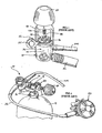
- a scuba unit 10 of a design according to the prior art having a regulator assembly 12 and a tank 14 for compressed breathable gas.
- the scuba tank 14 is a steel or aluminum cylinder designed to contain compressed gas in the range of 206,8 to 344,7 bar (3,000 to 5000 psi).
- the most preferred breathable gas is simply compressed air.
- gas mixtures are also used, such as nitrogen/oxygen blends commonly referred to as Nitrox or other gas blends including various other inert gases.
- breathable gas or compressed air are intended to also include other types of gas mixtures both common and uncommon to the scuba diving industry and/or other industries in which breathable gas is supplied, such as the medical industry, firefighting, emergency rescue, etc.
- Another compressed gas mixture that may benefit from the present invention includes argon, which is occasionally used in conjunction with dry suit inflation rather than breathable gas mixtures.
- the tank 14 of the scuba unit 10 may include a gas inlet/outlet scuba tank valve 16 comprising a scuba tank valve body 18 with a threaded portion for detachably coupling the scuba tank valve body 18 to the tank 14.
- the tank valve 16 additionally comprises a hand operated control knob 20 for opening and closing the tank valve 16 and an inlet/outlet opening 22.
- the opening 22 generally includes a recessed area 24 which contains a small orifice 26 that communicates with the interior of the tank 14 through the scuba tank valve body 18.
- An annular ridge 28 surrounds the recessed area 24 to form an annular groove wherein a removable o-ring 30 is disposed between the ridge 28 and the recess 24.
- This arrangement provides an airtight seal at the opening 22 when a regulator is connected thereto.
- This particular arrangement for the tank valve 16 is suitable for attachment to a yoke-type regulator.
- Another tank inlet/outlet arrangement (not illustrated) commonly used is designed for attachment to a DIN valve.
- the ridge 28 is in the form of a collar which projects substantially outwardly from the scuba tank valve body 18 and includes threads that are designed for engagement with a DIN valve regulator.
- the regulator assembly 12 is usually a dual or two-stage regulator including a first stage regulator member 32 and a second stage regulator member 33.
- the first stage regulator member 32 is detachably secured to the opening 22 of the tank valve 16 and is designed to reduce the gas pressure from the tank 14 from a pressure in the range of approximately 206,8 to 344,7 bar (3,000 to 5,000 psi) to an intermediate gas pressure of approximately 9,7 bar (140 psi).
- the intermediate pressure gas passes through a hose 36 to the second stage regulator member 33, wherein the gas pressure is further reduced to an ambient pressure that depends upon the depth of the scuba diver. In this manner, the diver can readily breathe the gas from the second stage regulator member 33 at any depth.
- a regulator housing 34 includes a gas inlet opening 38 which is surrounded by a raised collar or flange 40.
- a metal filter member 42 is positioned within the regulator housing 34 below the opening 38 for the purpose of filtering any and all gas and other materials entering the opening 38.
- a C-clip 44 is utilized to hold the filter 42 in the opening 38.
- a nut 46 maintains a yoke 48 in position in the vicinity of the opening 38.
- the yoke 48 is typically a U-shaped or an A-shaped element that is sized to permit the tank valve 16 to be positioned between the collar 40 and the top of the yoke 48
- a hand knob 50 with a screw member 52 passes through the top of the yoke 48 and is designed to tighten against the backside 53 of the tank valve 16 to press the collar 40 against the ridge 28 and o-ring 30 of the tank valve 16 to secure the two members together.
- the nut 46, the collar 40, the filter 42 and the C-clip 44 are all part of a valve housing having a threaded portion for securing the valve housing to a bore in the regulator housing 34. In other designs, these components are individually mounted within the bore as an integral part of the regulator housing 34.
- a dust cover 54 is typically employed to prevent water from entering the regulator 32 through the inlet opening 38.
- the dust cover 54 is generally made of plastic or rubber and is removably positioned over or against the collar 40 when the first stage regulator member 32 is not in use.
- the screw 52 is tightened against the top 56 of the dust cover 54 to press the dust cover 54 firmly against the inlet opening 38, thereby preventing entry of water and other contaminants.
- a similar removable cap arrangement is utilized for the second stage regulator alternate air source. Unfortunately, it is a common mistake to forget to place the dust cover 54 over the inlet opening 38 before rinsing the regulator assembly 12, thereby flooding the first or second stage regulator members 32, 33. Even when the dust cover 54 is properly positioned, it may not be sufficiently tight to prevent entry of water into the inlet opening 38. Certain embodiments disclosed herein obviate the requirement for the dust cover 54 and the entire problem inherent with its use.
- a gas regulator with a gas valve comprising a barrier that incorporates different materials, structures, and/or mechanisms to selectively allow the passage of compressed gas, while precluding the passage of contaminants such as liquids, solids, or airborne particulate into the regulator.
- the barrier automatically blocks the entry of contaminants into the regulator system when the gas regulator is not connected to the scuba tank or another source of compressed air or other gas.
- the barrier's performance is pressure sensitive and comprises a material which is porous to compressed gas, but which substantially prevents a low-pressure liquid from advancing through the passageway downstream of the barrier.
- the barrier comprises a movable cap that is adapted to cover an inlet opening of the gas regulator, wherein the movable cap is biased towards a first position in which the movable cap covers the inlet opening.
- the movable cap has a range of motion between the first position and a second position wherein the movable cap is displaced from the inlet opening when a scuba tank or other source of compressed air is attached.
- the barrier helps to protect the internal components of the gas regulator, such as filters and other types of gas conditioners.
- This automatic isolation of the internal passages of the gas regulator affords a clear advantage over prior art systems, since the components inside or connected to the gas regulator are automatically protected from exposure to contaminants.
- Another advantage includes a reduction or complete elimination of the time needed for cleaning the gas regulator and valve.
- a gas valve 120 comprises a valve housing 122, a barrier 124, and an (optional) gas conditioner 128.
- the valve housing. 122 has a passageway 130 with an upstream port 132 and a downstream port 134.
- the barrier 124 is disposed (in the embodiment of Figures 5-6) near the upstream port 132 and is configured to allow a compressed gas to flow through the barrier 124 and to substantially prevent a liquid or other types of contaminants from entering the passageway 130.
- the gas conditioner 128 is disposed such that the compressed gas flows through the gas conditioner 128.
- the gas conditioner 128 may comprise a filter that is disposed in the passageway 130 downstream of the barrier 124.
- the gas valve 120 is coupled to or integrally formed with a gas regulator.
- a member for controlling the pressure of gas flowing through the regulator is disposed downstream of the barrier 124.
- the gas valve 120 is, in certain embodiments, configured for use in a first stage regulator of a dual stage regulator system. Also, some embodiments are suited for use with a scuba tank containing compressed air. Such uses of the gas valve 120 are, however, illustrative only and this does not preclude the use of the gas valve 120 with other gas sources, gas types, and regulator systems. For instance, the gas valve 120 could be used in conjunction with a regulator system that is coupled to an air compressor or a storage tank containing compressed air or another gas suitable for a particular diving environment. Embodiments of the gas valve 120 may also be used in conjunctions with yoke-type connectors, DIN valve connectors, or any other connection system arrangements used for coupling a scuba regulator to a gas supply source or rebreather unit.
- the valve housing 122 has an upstream side 136 and a downstream side 137, and is preferably made of a water-resistant material such as a galvanized metal.
- the valve housing 122 preferably comprises a threaded portion 138 that engages the bore of a first stage regulator housing such as, without limitation, the housing 34 discussed above.
- the threaded portion 138 screws into the first stage regulator housing and the valve housing 122 is tightened using a nut-shaped portion 140.
- the nut-shaped portion 140 may also be used to hold a yoke such as, without limitation, the yoke 48 discussed above for securing the tank valve 16 to the first stage regulator.
- an o-ring 142 is used to maintain a watertight and airtight seal between the gas valve 120 and the first stage regulator housing.
- the valve housing 122 may further comprise a sealing face, preferably in the form of a raised collar 144, which is configured to engage an o-ring attached to a scuba tank valve.
- a groove 148 is circumferentially disposed within collar 144 and may serve to provide a channel for draining water away from the upstream port 132.
- the passageway 130 serves as a duct or conduit through which the gas from the scuba tank flows through the valve 120 and, where applicable, into the regulator system.
- the passageway 130 may also contain further components of the gas valve 120.
- the upstream port 132 and/or barrier 124 is preferably located at the upstream side 136 of valve housing 122 (for example, near the raised collar 144), since this location facilitates keeping water and other contaminants away from the upstream port 132 and/or barrier 124.
- the entrance port and/or barrier 124 may be located further down towards the downstream side 137 of the valve housing 122 inside the passageway 130.
- the passageway 130 may further comprise a groove or slot 152 located near the downstream side 137 of the valve housing 122 for securing the gas conditioner 128 (where employed) with a clip 154.
- the gas conditioner 128 is disposed near the downstream port 134 of the gas valve 120.
- the gas conditioner 128 may be disposed at a different location along the passageway 130, for instance near, just below or against the downstream end of the barrier 124.
- the gas conditioner 128 may comprise a filter that filters out particles and other contaminants in the air as it passes through the gas valve 120.
- the filter may comprise a fibrous metal filter having a conical shape as shown in Figure 5 or, alternatively, having the form of a flat disk. Other filter shapes or types may be employed as the gas conditioner 128.
- the gas conditioner 128 may also comprise a carbon material or a composition of calcium hydroxide, sodium hydroxide, and water such as DIVESORB TM (available from Dräger Group of the Federal Republic of Germany) for increasing the level of oxygen in the gas entering the gas valve 120. Such materials are used, for instance, in rebreather systems that recirculate air used by the diver.
- the gas conditioner 128 may comprise multiple elements that are disposed sequentially along the passageway 130, each (in one embodiment) serving a different purpose.
- the gas valve 120 does not include a gas conditioner 128.
- the gas conditioner 128 may be incorporated into the barrier 122.
- the barrier 122 may be formed of a material that acts both to keep water and other contaminants out of the gas valve 120 when the gas valve 120 is not connected to the scuba tank and to pass and filter compressed air flowing through the barrier 124 when the gas valve is connected to the scuba tank.
- a single element performs the functions of both of the gas conditioner 128 and the barrier 124.
- Such a barrier may comprise, for example, a multi-layered structure with barrier and filter layers bonded together and ,arranged sequentially in an upstream-downstream direction.
- the wall of the passageway 130 may be tapered below the upstream port 132 such that the diameter of the passageway 130 increases when moving downstream of the upstream port 132.
- the passageway 130 may comprise a lip 150 located near the upstream port 132 and configured for supporting the downstream end of the barrier 124. The lip 150 facilitates installation and removal of the barrier 124 from the upstream side of the valve housing 122.
- the passageway 130 may have substantially parallel inner walls (e.g., a substantially cylindrical passageway or one having a substantially constant square or rectangular cross-section.)
- the barrier 124 is preferably located at or near the upstream port 132 of the valve housing 122 and is also preferably at least partially contained inside the passageway 130.
- the barrier 124 may comprise any of the various types of material that are either waterproof or water resistant.
- the barrier 124 may comprise a rigid foam material or a rigid nonmetallic foam material.
- the barrier 124 may comprise a material porous to compressed gas such as an expanded polytetrafluoroethylene (e.g., GORE-TEX TM , which is available from Gore & Associates, Inc., of Newark, Delaware; Latex, Neoprene, or polyurethane).
- the barrier 124 plastically deforms when exposed to compressed air, while in other embodiments, the barrier 124 will not plastically deform when exposed to compressed air.
- the barrier 124 prevents low-pressure liquids and other contaminants (e.g., those that are at or near atmospheric pressure) from entering the passageway 130 downstream of the barrier 124.
- the upstream end of the barrier 124 may be substantially flush with (or alternatively, upstream of) the sealing face or the upstream surface of the raised collar 144, as illustrated in Figures 5 and 7.
- water that is splashed onto the outside surface of the barrier 124 will have a tendency to run off and be retained in the groove 148 of the raised collar 146. Any water remaining on the outside surface of the barrier 124 does not enter the passageway 130 because of the material properties and/or construction of the barrier 124.
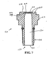
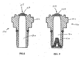
- the barrier 124 comprises a dome portion 155, as illustrated in Figures 8 and 9.
- Figure 8 illustrates a gas valve 120 that either contains no gas conditioner 128 in the passageway 130 or incorporates the functions of the gas conditioner 128 into the barrier 124.
- Figure 9 illustrates a gas valve 120 wherein the gas conditioner 128 is located near the downstream side 137 of the valve housing 122.
- the dome portion 155 of the barrier 124 in the illustrated embodiment may offer certain advantages such as the ability to more readily direct water and other contaminants off of and away from the outside surface of the barrier 124.
- the dome portion 155 may comprise a resilient material (for example, a suitable material selected from those disclosed above for forming the barrier 124 that compresses when a scuba tank valve is attached and returns to its original dome shape when the scuba tank is again disconnected.
- a spring or other similar device may be used maintain the dome shape of the barrier 124.
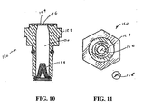
- the barrier 124 may comprise a membrane with a slit 156.
- the barrier 124 may be made of non-porous material such as latex, rubber, silicone, or any suitable polymer.
- the membrane-type barrier 124 may be made of a porous material that is not penetrated by water and other contaminants at atmospheric pressure.
- the slit in the membrane experiences a pressure that stretches the barrier surface and causes the slit to open, thus allowing the gas to enter the passageway 130 of the gas valve 120.
- the membrane of the barrier 124 is no longer under pressure and the slit 156 returns to its original closed position, once again preventing the entrance of low-pressure liquids (e.g., water) and other contaminants into the passage 130 of the gas valve 120.
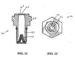
- the barrier 124 comprises a membrane with a pinhole 157.
- the pinhole 157 prevents water and contaminants from entering into the passageway 130 of the gas valve 120 when the scuba tank is not connected, but stretches to allow the passage of compressed gas when the gas valve 120 is connected to the scuba tank.
- the use of a pinhole 157 may offer certain designed advantages over the slit 156. For instance, the value of the predetermined activation pressure may be increased by using a pinhole rather than a slit.
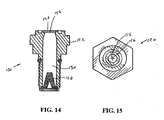
- the barrier 124 of the gas valve 120 comprises a membrane containing a plurality of slits 156.
- the membrane comprises two slits 156 of substantially equal length that are in the form of a cross.
- the barrier 124 may comprise more than two slits 156, or the slits 156 may be of different lengths and/or cut to different depths into the membrane.
- the barrier 124 may comprise a membrane having a combination of one or more slits 156 with one or more pinholes 157 to provide a particular membrane performance. The number and characteristics of the slits 156 and/or pinholes 157 placed in the membrane may be selected such that a desired performance is achieved, for example; the predetermined pressure at which the barrier 124 allows for the passage of a compressed gas.
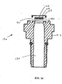
- the gas valve 120 comprises a retainer 158 that is detachably coupled to the valve housing 122 and secures the barrier 124 within the passageway 130 or the valve housing 122.
- the retainer 158 When attached to the valve housing 122, the retainer 158 preferably contacts a least a portion of the outside surface 159 of the barrier 124 so as to secure the barrier 124 to the valve housing 122.
- the retainer 158 preferably has an open portion that leaves at least a portion of the upstream end 159 of the barrier 124 exposed to the environment so as to allow compressed gas to flow through the barrier 124 when the valve 120 is connected to a pressurized gas source.
- the retainer 158 preferably comprises a threaded portion 160 for attaching the retainer 158 and the barrier 124 to the valve housing 122.
- the retainer 158 may utilize a snap-on configuration for attaching the retainer 158 and the barrier 124 to the valve housing 122.
- other devices and/or means are used in place of or in combination with the retainer 158 for securing the barrier 124 to the valve housing 122.
- the diameter of the barrier 124 may be made slightly larger than the inner diameter of the lip 150 of the valve housing 122.
- the barrier 124 is secured to the valve housing 122 by utilizing an interference fit of the barrier 124 with an inner diameter of the lip 150.
- an adhesive or bonding compound may be used for attaching the barrier 124 to the valve housing 122.
- the gas valve 120 which may be part of a gas regulator as discussed above, comprises a cartridge 160.
- the cartridge may comprise the barrier 124, which is formed from a material which is porous to compressed gas but which substantially prevents a low-pressure liquid from advancing through the passageway 130 downstream of the barrier 124.
- the cartridge 160 may contain a plurality of elements, for instance a first element 162, a second element 164, and a third element 168.
- the first element 162 comprises the barrier 124
- the second element 164 comprises a carbon material or DIVESORB TM
- the third element 168 comprises a post filter that collects excess carbon in the second element 164 and that otherwise filters the gas passing through the passageway 130.
- the first element 162 of the cartridge 160 comprises a pre-filter that is used in conjunction with the filter of the third element 168.
- the gas valve 120 either does not contain the barrier 124 or the barrier 124 is attached upstream of the first element 162 of the cartridge 160.
- Other combinations of barriers and gas conditioners are also consistent with embodiments of the valve regulator 120.
- the cartridge 160 may also comprise more or fewer elements than the three elements 162, 164, 168 of the illustrated embodiment.
- the cartridge 160 may be formed so as to substantially fill the passageway 130 of the valve housing 122, as illustrated in Figure 17.
- the barrier may be any of the various embodiments of the barrier 124 illustrated or suggested herein.
- the first element 162 may protrude above the surface of the raised collar 144, as illustrated in Figure 17, or alternatively, may be flush with the surface of the raised collar 144, as illustrated, for example, in Figures 5 and 7.
- the gas valve 120 may be integrated into a gas regulator 170 comprising a regulator housing 34 containing further components for regulating the flow and/or pressure of gas from a high-pressure source such as a scuba tank as shown above.
- a high-pressure source such as a scuba tank as shown above.
- Embodiments of the gas valve 120 may be used in conjunction with a yoke-type connection, a DIN valve connection, or other less common connector systems, such as those utilized in technical diving and rebreather units.
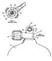
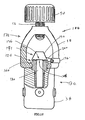
- Figures 19 and 20 show the use of the gas valve 120 with a gas regulator 170 having a yoke-type connector 172.
- the yoke-type connector 172 comprises the yoke 48, the screw member 52, and the hand knob 50.
- the yoke-type connector 172 is preferably attached to the gas regulator 170 using the nut-shaped portion 140 of the valve housing 122.
- the yoke-type connector 172 may be used to attach a tank valve, such as the tank valve 16, by screwing the screw member 52 onto the tank valve 16 using the hand knob 50.
- the tank valve 16 comprises a knob 184 that may be used to deliver compressed gas from the scuba tank once the tank valve 16 is securely fastened to the gas regulator 170.
- the gas regulator 170 comprises an inlet opening 186, the passageway 130, which extends downstream of the inlet opening 186, and an attachment portion 188 near the inlet opening 186, which is configured for connecting the regulator 170 to a pressurized gas source.
- the regulator 170 further comprises the barrier 124 in the form of a movable cap 190.
- the attachment portion 188 is disposed near the inlet opening 186 and is configured for connecting the regulator 170 to a pressurized gas source such as a scuba tank.
- the movable cap 190 is adapted to cover the inlet opening 186 and has a range of motion between a first position 191 (Figure 19), wherein the movable cap 190 covers the inlet opening 186, and a second position 192 ( Figure 20) outside of the passageway 130, wherein the movable cap is displaced from the inlet opening.
- the movable cap 190 is biased towards the first position 191 by a biasing element 194.
- the gas regulator 170 may also comprise an attachment device 196 for coupling the movable cap 190 and for the biasing element 194 to the gas regulator 170.
- the attachment portion 188 is configured to mate with tank valve 16 to form a gas-tight seal when coupled to the regulator 170 using the screw member 52.
- the tank valve 16 comprises an o-ring that mates against the surface of the raised collar 144 of the valve housing 122 to form the gas-tight seal.
- the movable cap 190 is preferably made of a substantially non-porous material such as a metal or plastic.
- the movable cap 190 is preferably rigid, but may also be made of a softer material, such as rubber, so long as it has a sufficiently rigid form to remain in place over the inlet opening 186 when the regulator 170 is disconnected from the tank valve.
- a seal is formed near the upstream side 136 of the valve housing 122 that prevents water splashed onto or surrounding the regulator 170 from entering the passageway 130.
- the movable cap 190 may incorporate an o-ring (not shown) that mates with a portion of the raised collar 144 to aid in forming the seal.
- the movable cap 190 may be sufficiently soft so as to form a seal around the inlet opening 186.
- the surface of the movable cap 190 that mates with the raised collar 144 may be formed with a protruding annular portion that fits inside the groove 148 and/or overhangs or surrounds the outer circumference of the raised collar 144.
- the biasing element 194 comprises a spring hinge 198 attached to an arm 200 for coupling the movable cap 190 to the attachment device 196.
- the spring hinge 198 biases the cap 190 toward the first position 191.
- the movable cap 190 pivots about the spring hinge 198, which produces a larger torque on the arm 200 as the movable cap 190 moves from the first position 191 to the second position 192.
- the biasing condition created by the spring hinge 198 is advantageous, since it automatically locates the movable cap 190 to the first position 191 whenever the regulator 170 is disconnected from the tank valve 16.
- the biasing element 194 may be formed by making the arm 200 of a resilient material and disposing the movable cap 190 so that it is in the first position 191 when the arm 200 is in an unstressed or low-stress state. As the movable cap 190 is moved to the second position 192, stresses increase in the arm 200 to produce a torque that biases movable cap 190 back towards the first position 191. Other devices or means in the art may be used to form a suitable biasing element 194 for biasing the movable cap 190 towards the first position 191.
- the attachment device 196 used to couple the movable cap 190 to the gas regulator 170, comprises any of the various devices and techniques used in the art.
- the attachment device 196 may comprise a clamp that fits around a portion of the yoke 48, as illustrated in Figures 19 and 20.
- the attachment device 196 may comprise a threaded base that is screwed into a portion of the body of the gas regulator 170.
- An alternative base could also be in the form of an annular ring that fits between the yoke 48 and the nut-shaped portion of the valve housing 122.
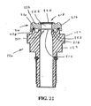
- a cap 210 is used with the gas valve 120 of a regulator such as, without limitation, the first stage regulator 32 discussed above, wherein the gas valve 120 has an inlet opening 212 and an inlet sealing face 214 surrounding the inlet opening 212.
- the cap 210 comprises a cap body 216 having an upstream side 218 and a downstream side 220 and a cap opening 222 extending from the upstream side 218 to said downstream side 220.
- the cap body 216 forms a cap sealing face 223 on said downstream side 220.
- the cap 210 further comprises a barrier 224, which is disposed across the cap opening 222 and is formed from a material which is porous to compressed gas but which substantially prevents passage of low-pressure liquid downstream of the downstream end of said barrier 224.
- the cap 210 protects the downstream portions of the valve 120 and/or regulator 132 from contamination via, inter alia, the barrier 224.
- the barrier 224 may be generally similar to any of the embodiments of the barrier 124 discussed above.
- the cap 210 may be configured for coupling to a valve housing that is specifically designed for use with the cap 210.
- the cap 210 may be configured for coupling to a valve housing made according to conventional design or any other commercially available design. In such cases, the cap 210 allows any suitable gas valve to take advantage of the benefits offered by embodiments of the barrier 124 previously described herein.
- the cap 210 may be attached to the valve housing 122 of the gas valve 120 using attachment means common in the art.
- the cap 210 could have through holes (not shown) in the cap body 216 corresponding to tapped holes (not shown) in the valve housing 122.
- the cap body 216 is attached to the valve housing 122 by running screws or bolts into the holes in the cap body 216 and the valve housing 122.
- An o-ring 230 may be used as the cap sealing face 223 of the cap body 216 and/or the inlet sealing face 214 of the valve housing 122.
- the cap 210 could be manufactured with an annular lip 228 configured with an inner diameter for press fitting the cap body 216 onto the valve housing 122.
- the annular lip 228 may have threads (not shown) for screwing the cap 120 onto the valve housing. Other threaded engagement systems may also be employed. In yet other alternatives, an adhesive, glue, epoxy, or solder could be used to attach the cap body 216 to the valve housing 122. As still another alternative, no attachment means may be employed.
- the inlet sealing face 214 of the valve housing 122 may comprise a flat annular surface or a raised collar like the raised collar 144 with the groove 148, as shown in Figure 21. Other configurations of the inlet sealing face 214 may be used to accommodate the interfacing between the cap body 216 and the valve housing 122.
- the cap 210 further comprises a source sealing face 232 disposed at the upstream side of the cap body 216.
- the source sealing face 232 may be used to accommodate the tank valve 16 of the scuba tank 14.
- the source sealing face 232 is similar to the inlet sealing face 214, for example when the cap 210 is used on a gas valve made for use with a yoke-type fitting.
- the barrier 224 extends across the upstream end of cap opening 222 and the upstream end of the barrier 224 may be substantially flush with the source sealing face 232, as illustrated in Figure 21.
- the barrier 224 is preferably at least partially disposed within cap opening 222.
- a method of providing air to a scuba diver comprises providing the gas regulator 170 with the barrier 124, wherein the barrier 124 is formed from a material which is porous to compressed gas, but which substantially prevents a low-pressure liquid from advancing through the passageway 130 downstream of the barrier 124.
- the method further comprises connecting a source of compressed gas to the gas valve 120.
- the method also comprises flowing compressed gas through the barrier 124.
- the method also comprises conditioning the compressed gas to a condition wherein a human may breathe the gas.
- the gas regulator 170 may be incorporated into a prior art scuba unit such as the scuba unit 10 in Figure 4.
- the gas regulator 170 is assembled by installing the gas valve 120 with a barrier 124 (which barrier 124 is constructed according to one or more of the embodiments discussed above) into the regulator housing 34 shown in Figure 1.
- the barrier 120 seals the upstream port 132 of the gas valve housing from the outside environment and liquid is substantially prevented from advancing though the passageways of the gas regulator 170.
- the internal portions of the gas regulator 170 are protected from contaminants such as water when not connected to the scuba tank 14.
- other structural components may be used reduce the amount of water or other liquids on top of the barrier 120, such as supplying the groove 148 of the raised collar 144 or forming the upstream side of the barrier 120 into a dome shape.
- the barrier 124 may contain one or more pinholes or slits that are closed when the barrier 124 is exposed to fluid(s) at atmospheric pressure, such as illustrated in Figures 10-15. Under such conditions, the barrier 124 may be made of an impermeable material that prevents the entry of a liquid into the gas regulator 170. Alternatively, the barrier 120 may be made of an expanded polytetrafluoroethylene (e.g., GORE-TEX TM ). In such cases, liquid contaminants such as water may partially soak into the barrier 124, but are prevented from advancing downstream of the downstream end of the barrier 124 while the barrier is exposed to liquid at or near atmospheric pressure.
- GORE-TEX TM expanded polytetrafluoroethylene
- a small amount of water or contaminants might be blown through the gas valve when the scuba tank is attached and the scuba tank valve is open; however, the small amount of contaminant quickly passes through and out of the regulator, thus precluding a negative impact on the gas regulator 170.
- the gas regulator 170 is attached to the scuba tank 14 and the scuba tank valve 16 is opened. Since the barrier 124 is porous to compressed gas, the compressed gas passes through the gas regulator and to the diver. When the scuba tank 14 is later removed, the barrier 124 is at atmospheric pressure and liquid is again substantially prevented from advancing though the passageways of the gas regulator 170.
- the method of providing air to a scuba diver may further comprise flowing compressed gas through the barrier 124.
- the method also comprises conditioning the compressed gas to a condition wherein the gas may be breathed by a human.
- Conditioning may comprise reducing the pressure of the air from the source to a pressure suitable for breathing.
- Conditioning may further comprise adapting the air for use by a scuba diver or adapting the air for use in a respiration system.
- the method may further comprise installing the gas valve in to a regulator.
- a method of providing air to a scuba diver comprises providing a gas regulator 170 with the inlet opening 186 and the movable cap 190, wherein the movable cap 190 is biased toward the first position 191 wherein the movable cap 190 covers the inlet opening 186 of the gas valve 120.
- the method further comprises connecting a source of compressed gas to the gas valve 120.
- the method also comprises connecting the source of compressed gas and moving the movable cap 190 to a second position wherein the movable cap 190 is displaced from the inlet opening 186.
- the method also comprises flowing compressed gas through the opening.
- the method also comprises conditioning the compressed gas to a condition wherein a human may breathe the gas.
- the gas regulator 170 is assembled as discussed above herein.
- the movable cap 190 Prior to connection of the gas regulator 170 to the scuba tank 14, the movable cap 190 is in the first position 191. With the movable cap 190 in the first position 191, the inlet opening 186 of the gas valve 120 is covered and sealed such that contaminants are blocked form entering the passageways of the gas regulator 170.
- the gas regulator 170 is attached to the scuba tank 14 and the scuba tank valve 16 is opened.
- the movable cap 190 is moved from the first position 191 shown in Figure 19, to the second position 192 shown in Figure 20.
- the inlet opening 186 of the gas valve 120 is accessible for connecting the gas regulator 170 to the scuba tank valve 16.
- the movable cap 190, and associated hardware are configured so that the movable cap 190 is actuated by the attachment of the scuba tank valve 16 to automatically move from the first position 191 to the second position 192.
- the movable cap 190 may be manually actuated. In such embodiments, prior to attaching the gas regulator 170 to the scuba tank 14, the diver moves the moveable cap 190 by hand by overcoming the force of the biasing element 194.
- the movable cap 190 When the scuba tank 14 is later removed, the movable cap 190 returns to the first position 191, again covering the inlet opening 186 of the gas valve 120 so as to prevent contaminants from entering the interior passageways of the gas regulator 170.
- the biasing element 194 is not present and the inlet opening 186 is covered by manually moving the movable cap 190 from the second position 192 to the first position 191.
- Either of the above methods of providing air to a scuba diver may further comprise flowing compressed gas through the barrier 124.
- the method also comprises conditioning the compressed gas to a condition wherein the gas may be breathed by a human.
- Conditioning may comprise reducing the pressure of the air from the source to a pressure suitable for breathing.
- Conditioning may further comprise adapting the air for use by a scuba diver or adapting the air for use in a respiration system.
- the method may further comprise installing the gas valve in to a regulator.
- Embodiments of the gas regulator 170 incorporating the gas valve 120 provide a relatively simple, yet very effective, arrangement for preventing the inadvertent entry of water and other contaminants into the first or second stage regulator members of a scuba diving unit. Embodiments of the gas regulator 170 eliminate the requirement that the user of a scuba diving unit remember to place a dust cap over the entrance port of the gas valve and eliminate or reduce the need to clean the gas regulator after use.
- Embodiments of the gas valve 120 may also be utilized with second stage regulators when in the form of an alternate air source.
- the gas valve 120 may be utilized with any type of gas used in the scuba diving industry, including various types of breathable gas mixtures, as well as other types of systems that are used in scuba diving but not necessarily for breathing.
- embodiments of the gas valve 120 may be used in conjunction with cylinders of compressed argon for inflating dry suits.
- extended range scuba divers require the use of multiple compressed breathing gas tanks for decompression purposes. As such, the scuba diver, when performing such extended range functions, must change regulator connections between tanks while underwater.
- Embodiments of the gas valve 120 may be used to obviate these problems and facilitate changing of compressed gas bottles while underwater.
- embodiments of the gas valve 120 may also be utilized in an inlet valve arrangement for rebreather scuba units.
- Embodiments of the present invention should not be limited by the specific illustrations and embodiments described in detail above. While the embodiments of the present invention were initially developed for the scuba diving industry, those skilled in the art will appreciate the embodiments of the gas regulator 170, gas valve 120, and the gas valve 120 have much broader implications and applications.
- the gas valve 120 may be utilized in a variety of fluid flow environments and devices and should not, therefore, be limited to gaseous fluids. Various types of devices or systems wherein fluid under pressure is directed into a one-way inlet valve may benefit from the embodiments of the present invention.
- Embodiments of the present invention may be used in a variety of applications and environments where protection from the entry of contaminant is desirable when the valve is disconnected from a supply source.
- Examples include an inlet valve, a gas valve, a medical regulator for oxygen, air or other gases, a welding gas regulator, a second stage diving regulator, an inflator hose valve, buoyancy gas valve, a quick disconnect valve, a quick disconnect hose, or any other kind of gas valve where avoidance of contamination is desirable.
Abstract
Description
- The present invention is directed to a gas valve, and more specifically, to a gas valve for use in a gas regulator that allows entry of a compressed gas, but blocks the entry of contaminants into the gas regulator.
- Scuba tanks generally utilize a pressurized source of breathable gas, such as compressed air as well as mixed gas blends, having pressures in the range of 206,8 to 344,7 bar (3,000 to 5000 psi). A two stage pressure reduction system is typically used to deliver the gas to a scuba diver at a pressure that is within an appropriate pressure range for underwater diving. A first stage regulator reduces the pressure of gas from the scuba tank to an intermediate pressure range of 8,3 to 9,7 bar (120 to 140 psi), while a second stage regulator, typically incorporated into a breathing mask, regulates the flow of gas delivered to the diver to a pressure that depends on the depth of the diver in the water.
- First stage regulators are generally connected to the scuba tank using one of two types valve connection arrangements: yoke-type connection or DIN valve connection. In yoke-type connection systems, the regulator comprises a round opening that is filled by a metal filter surrounded by a raised collar with an o-ring. The scuba tank has an inlet/outlet tank valve with a small aperture located near the middle of a round recessed area. The raised collar of the regulator valve fits snugly within the recessed area of the tank valve. A hand knob is used to secure the tank valve and to form a seal at the o-ring. With a DIN valve connection, the first stage regulator screws directly into the scuba tank valve outlet opening using either five or seven threads, depending upon the pressure to be contained within the tank. Other, less common, connection arrangements are also available, such as those utilized in technical diving and rebreather units.
- The dual stage regulator system is attached to a tank valve using a hand knob with a screw member that is part of the regulator assembly. Once the first stage regulator is attached to the scuba tank, an closed system is formed between the input of the first stage regulator and the input of the second stage regulator that is unexposed to the ambient environment. However, the interior components of the first stage regulator can potentially become exposed to external contaminants such as salt water, fresh water, wash water, airborne particulates, and the like when the regulator is not connected to the scuba tank. Such contamination can rust and corrode critical regulator components such as metal air filters and lead to the clogging of small apertures or orifices. This can lead to potentially catastrophic consequences during use of the regulator system due to partial or complete failure of the equipment.
- A dust cover is usually attached to the first stage regulator for covering the entrance port of the first stage regulator when the regulator is not attached to the scuba tank, thus preventing the entrance of contaminants into the regulator system. The cover is typically held in place using the same hand knob that is used for attaching the scuba tank. Between or after dives it is, however, easy for the diver to either forget to attach the cover or simply decide this precaution is unnecessary.
- In order to avoid this dependence on the diver to protect the internal components of the regulator system by manually attaching the dust cover, it would be beneficial to have a regulator control valve that automatically seals the entrance port of the regulator from contaminants such as water when the scuba tank is disconnected and/or when pressure near the entrance port of the first stage regulator is below a predetermined minimum.
- One solution for automatically covering the entrance port of a first stage regulator when the scuba tank is not connected is disclosed in
U. S. Patent Application Number 09/872,130 . In this device, a piston is disposed inside the regulator valve near the entrance port The piston is biased to a closed position that covers the regulator valve entrance port, thereby preventing the entrance of water and/or other possible contaminants when a scuba tanks is not connected. When the scuba tank is connected to the regulator valve and the tank valve is opened, gas pressure overcomes the bias force on the piston, thus opening the regulator valve to allow the passage of gas. -
US-A- 5,685,297 relates to a freeze resistant first stage pressure regulator for use with a high pressure source of breathable gas that includes a housing and a yoke, for attaching said housing to a high pressure source of breathable gas along with a pressure regulated outlet, a valve seat and a piston. - One exemplary aspect involves a gas valve comprising a housing and a barrier. The housing has a passageway with an upstream port and a downstream port. The barrier is disposed across the passageway and is formed from a material which is porous to compressed gas but which substantially prevents a low-pressure liquid from advancing through the passageway downstream of the barrier. The passageway may further comprise a gas conditioner and/or a filter that is preferably disposed downstream of the barrier, but which may also be disposed upstream of the barrier.
- The barrier may be substantially immobile in an upstream-downstream direction when exposed to compressed gas and comprise various forms and materials. For instance, the barrier may comprise a dome portion that protrudes beyond the surface of an entrance port of the valve. The barrier may also comprise a waterproof membrane, a nonmetallic foam material, or a rigid foam material. For example, the barrier may comprise an expanded polytetrafluoroethylene such as GORE-TEX™. In certain embodiments, the barrier plastically deforms when exposed to compressed air, while in other embodiments, the barrier will not plastically deform when exposed to compressed air. In yet other embodiments, the barrier is a membrane, which may comprise one or more slits and/or pinholes. The membrane may comprise a cross in the form of two orthogonal slits.
- In another exemplary aspect the gas valve further comprises a gas regulator in fluid communication with the passageway. The barrier is disposed across the passageway and is formed from a material which is porous to compressed gas but which substantially prevents a low-pressure liquid from advancing through the passageway downstream of the barrier.
- An aspect of the present invention involves a gas regulator for use in regulating the flow of a compressed gas. The gas regulator comprises a valve. The valve comprises housing having a passageway with an upstream port and a downstream port, a barrier disposed across a passageway, and a filter disposed in the passageway downstream of the barrier. The gas regulator further comprises a gas pressure control member located downstream of the valve. The gas regulator may also comprise a filter disposed in the passageway downstream of the barrier. The gas regulator further comprises a cap detachably coupled to the housing for securing the barrier to the valve. The cap may comprise a threaded portion or a snap for securing the barrier to the valve.
- Yet another exemplary aspect involves a gas regulator comprising a housing having a passageway with an upstream port and a downstream port The valve further comprises a cartridge disposed in the passageway. The cartridge comprises a barrier formed from a material which is porous to compressed gas but which substantially prevents a low-pressure liquid from advancing through the passageway downstream of the barrier. The cartridge further comprises a gas conditioner downstream of the barrier.
- In certain embodiments, the gas conditioner abuts the downstream end of the barrier. The gas conditioner may comprise a filter. In other embodiments, the gas conditioner comprises a first stage and a second stage downstream of the first stage. The first stage is a filter and the second stage comprises a composition of calcium hydroxide, sodium hydroxide, and water such as DIVESORB™. The gas conditioner may comprise a gas pressure control member.
- In yet another exemplary aspect a cartridge for use with a gas valve comprises a barrier and a gas conditioning element. The barrier is formed from a material which is porous to compressed gas but which substantially prevents a low-pressure liquid from advancing through the passageway downstream of the barrier. The gas conditioner is downstream of the barrier. The valve may further comprise gas regulator in fluid communication with the passageway.
- In certain embodiments, the gas conditioner abuts the downstream end of the barrier. The gas conditioner may comprise a filter. In other embodiments, the gas conditioner comprises a first stage and a second stage downstream of the first stage. The first stage is a filter and the second stage comprises a composition of calcium hydroxide, sodium hydroxide, and water such as DIVESORB™. The gas conditioner may comprise a gas pressure control member.
- Another aspect of the invention involves a valve comprising an inlet opening, a passageway extending downstream of the inlet opening, an attachment portion near the inlet opening, and a movable cap adapted to cover the inlet opening. The cap has a range of motion between a first position, wherein the cap covers the inlet opening, and a second position outside of the passageway, wherein the cap is displaced from the inlet opening. The cap is biased towards the first position. The gas valve may further comprise a gas regulator in fluid communication with the passageway.
- In certain embodiments, the cap is adapted to move from the first position to the second position when the valve is attached to a source of compressed gas. In other embodiments, the cap is adapted to automatically move from the second position to the first position when the valve is disconnected from a source of compressed gas. The valve may further comprise an attachment device for coupling the cap to the valve.
- Yet another aspect of the invention involves a cap for use with a gas valve having an inlet opening and an inlet sealing face surrounding the inlet opening. The cap comprises a cap body having an upstream side and a downstream side and a cap opening extending from the upstream side to the downstream side The body forms a cap sealing face on the downstream side. The cap further comprises a barrier disposed across the cap opening. The barrier is formed from a material which is porous to compressed gas but which substantially prevents passage of low-pressure liquid downstream of a downstream end of the barrier.
- In certain embodiments, the cap further comprises a source sealing face disposed at the upstream side of the body. The source sealing face may be similar to the inlet sealing face. The barrier may extend across an upstream end of the cap opening.
- An exemplary aspect involves a method of providing breathable air. The method comprises providing a gas valve with a barrier formed from a material which is porous to compressed gas, but which substantially prevents a low-pressure liquid from advancing through a passageway downstream of the barrier. The method additionally comprises connecting a source of compressed gas to the valve. The method further comprises flowing compressed gas through the barrier. The method also comprises conditioning the compressed gas to a condition wherein the gas may be breathed by a human.
- Conditioning may comprise reducing the pressure of the air from the source to a pressure suitable for breathing. Conditioning may further comprise adapting the air for use by a scuba diver or adapting the air for use in a respiration system. The method may further comprise installing the gas valve in to a regulator.
- An aspect of the invention involves a method of providing breathable air. The method comprises providing a gas valve with a barrier formed from a material which is porous to compressed gas, but which substantially prevents a low-pressure liquid from advancing through a passageway downstream of the barrier. The method additionally comprises connecting a source of compressed gas to the valve. The method also comprises, while connecting the source of compressed gas, moving the cap to a second position wherein the cap is displaced from the inlet opening. The method also comprises flowing compressed gas through the opening. The method additionally comprises conditioning the compressed gas to a condition wherein the gas may be breathed by a human.
- Conditioning may comprise reducing the pressure of the air from the source to a pressure suitable for breathing. Conditioning may further comprise adapting the air for use by a scuba diver or adapting the air for use in a respiration system. The method may further comprise installing the gas valve in to a regulator.
- The foregoing features, aspects, and advantages of the present invention will now be described with reference to the drawings of preferred embodiments that are intended to illustrate and not to limit the invention. The drawings comprise 21 figures.
- A further exemplary aspect comprises a gas valve, which has a housing having a passageway with an upstream port and a downstream port that is intended to transport a compressed gas from the upstream port to the downstream port; and a barrier disposed across the passageway, the barrier may be formed from a material which is porous to the compressed gas but which is arranged to substantially prevent a low-pressure liquid from advancing through the passageway downstream of the barrier means.
- The valve may also have a gas conditioner connected to the gas valve.
- The valve may also have in which the gas conditioner is connected to valve at a location that is downstream of the barrier. The valve may also have in which the gas conditioner is connected to valve at a location that is upstream of the barrier.
- The valve may also have a gas conditioner that may be a filter, a metallic filter, a non-metallic filter, a composition of calcium hydroxide and sodium hydroxide and water, DIVESORB™, a gas pressure regulating device, or a carbon filter.
- The valve may also have a barrier that is made with material such as a polytetrafluoroethylene, an expanded polytetrafluoroethylene, GORE-TEX™, a water resistant material, a predetermined semi-permeable membrane, a water resistant membrane, a water proof membrane, a foam material, a rigid foam material, a fibrous material, a dome-shaped porous material, or a nonmetallic foam material.
- The valve may also have a barrier that is arranged to be substantially immobile in an upstream-downstream direction when exposed to compressed gas.
- The valve may also include a membrane having at least one opening such as a slit, a pinhole, a cross-shaped opening, or an expandable opening.
- The valve may also have a barrier that has an opening that is arranged to achieve an expanded condition when exposed to a relatively high pressure compressed gas so as to permit the high pressure compressed gas to pass through the opening in the barrier means and flow downstream of the passageway, and the opening may be arranged to achieve a closed condition when the high pressure compressed gas is removed so as to substantially prevent low pressure liquids from passing through the barrier means in the absence of the high pressure compressed gas.
- The valve according to the present invention comprises a barrier which is detachably coupled to the housing for securing the barrier to the housing.
- The valve according to the present invention may also have a barrier that is connected to the housing with a snap-on connection, a flexible snap on connection, a cap having a snap-on connection, and a threaded connection.
- The valve may also have a first stage gas regulator that is connected to the housing at a location that is downstream of the barrier, and a second stage gas regulator may be connected to the housing at a location that is downstream of both the first stage regulator and the barrier means, so that the barrier significantly prevents liquid contamination of the first stage gas regulator and the second stage gas regulator by substantially preventing the low pressure liquid from flowing downstream from the barrier means.
- The first stage gas regulator and the second stage gas regulator can be arranged to provide a life supporting breathable gas supply for a human, and the barrier can be arranged to be able to significantly reduce the possibility of the life supporting breathable gas supply from experiencing structural failures that can result from liquid contamination.
- Another exemplary aspect comprises a method. The method comprises providing a housing having a passageway with an upstream port and a downstream port that is intended to transport a compressed gas from the upstream port to the downstream port; and providing a barrier disposed across the passageway. The barrier in from of a movable cap substantially prevents a low-pressure liquid from advancing through the passageway downstream of the barrier.
- This method can also include a gas regulator that is connected to the housing at a downstream location that is downstream of the barrier, and the gas regulator can have moving parts arranged to create a reduction in pressure to the compressed gas, and the barrier can be arranged to be able to significantly prevent liquid contamination of the moving parts of the gas regulator by substantially preventing the low pressure liquid from flowing downstream of the barrier means and into the gas regulator.
- The gas regulator employed in this method can comprise a life supporting breathable gas supply for a human, and the barrier can be arranged to be able to significantly reduce the possibility of the life supporting breathable gas supply from experiencing structural failures that can result from liquid contamination.
-
- FIGURE 1 is a perspective view of a first-stage regulator of a yoke-type dual stage regulator assembly for a scuba diving unit
- FIGURE. 2 is a front plan view of the inlet valve arrangement of FIGURE 1 taken substantially along line 2-2 of FIGURE 1;
- FIGURE 3 is a front plan view of a gas outlet yoke-type connection valve of a scuba tank.
- FIGURE 4 is a top perspective view of the first stage regulator member of FIGURE 1 connected to the gas outlet yoke-type connection valve of the scuba tank of FIGURE 3;
- FIGURE 5 is a cross-sectional view of a valve for use with a gas regulator with a barrier that is porous to compressed gas.
- FIGURE 6 is a top view of the valve shown in FIGURE 5.
- FIGURE 7 is a cross-sectional view of a gas valve with a barrier that is flush with an entrance port into the valve.
- FIGURE 8 is a cross-sectional view of a gas valve with a dome shaped barrier at an entrance port into the valve.
- FIGURE 9 is a cross-sectional view of a gas valve having a dome shaped barrier at an entrance port into the valve and a conical shaped gas conditioner downstream of the barrier.
- FIGURE 10 is a cross-sectional view of a gas valve having a slit membrane at an entrance port into the valve.
- FIGURE 11 is a top view of the gas valve shown in FIGURE 10.
- FIGURE 12 is a cross-sectional view of a gas valve having a membrane with a pinhole at an entrance port into the valve.
- FIGURE 13 is a top view of the gas valve shown in FIGURE 11.
- FIGURE 14 is a cross-sectional view of a gas valve having a membrane with a pair of orthogonal slits at an entrance port into the valve.
- FIGURE 15 is a top view of the gas valve shown in FIGURE 14.
- FIGURE 16 is a cross-sectional view of a gas valve having a filter removably attached to the valve at an entrance port into the valve by a fastener.
- FIGURE 17 is a cross-sectional view of a gas valve comprising a filter cartridge
- FIGURE 18 is a cross-sectional view of the filter cartridge shown in FIGURE 17.
- FIGURE 19 is a side view of a gas valve according to the present invention with a movable cap that automatically covers the entrance port of the valve when not attached to a scuba tank.
- FIGURE 20 is a side view of the gas valve shown in FIGURE 19 showing an inlet/outlet scuba tank valve attached to the gas valve.
- FIGURE 21 is a cross-sectional view of a gas valve that is covered by a cap containing a barrier that is porous to compressed gas.
- These and other embodiments of the present invention will also become readily apparent to those skilled in the art from the following detailed description of preferred embodiments having reference to the attached figures; however, the invention is not limited to any particular embodiment(s) disclosed herein. Accordingly, the scope of the present invention is intended to be defined only by reference to the appended claims.
- Referring to Figures 1-4, a
scuba unit 10 of a design according to the prior art is illustrated having aregulator assembly 12 and atank 14 for compressed breathable gas. Typically, thescuba tank 14 is a steel or aluminum cylinder designed to contain compressed gas in the range of 206,8 to 344,7 bar (3,000 to 5000 psi). The most preferred breathable gas is simply compressed air. However, a variety of gas mixtures are also used, such as nitrogen/oxygen blends commonly referred to as Nitrox or other gas blends including various other inert gases. It should be understood, therefore, that when the terms breathable gas or compressed air are used in this application, such terms are intended to also include other types of gas mixtures both common and uncommon to the scuba diving industry and/or other industries in which breathable gas is supplied, such as the medical industry, firefighting, emergency rescue, etc. Another compressed gas mixture that may benefit from the present invention includes argon, which is occasionally used in conjunction with dry suit inflation rather than breathable gas mixtures. - The
tank 14 of thescuba unit 10 may include a gas inlet/outletscuba tank valve 16 comprising a scubatank valve body 18 with a threaded portion for detachably coupling the scubatank valve body 18 to thetank 14. Thetank valve 16 additionally comprises a hand operatedcontrol knob 20 for opening and closing thetank valve 16 and an inlet/outlet opening 22. When a yoke-type valve is used, theopening 22 generally includes a recessedarea 24 which contains asmall orifice 26 that communicates with the interior of thetank 14 through the scubatank valve body 18. Anannular ridge 28 surrounds the recessedarea 24 to form an annular groove wherein a removable o-ring 30 is disposed between theridge 28 and therecess 24. This arrangement provides an airtight seal at theopening 22 when a regulator is connected thereto. This particular arrangement for thetank valve 16 is suitable for attachment to a yoke-type regulator. Another tank inlet/outlet arrangement (not illustrated) commonly used is designed for attachment to a DIN valve. In such embodiments, theridge 28 is in the form of a collar which projects substantially outwardly from the scubatank valve body 18 and includes threads that are designed for engagement with a DIN valve regulator. - The
regulator assembly 12 is usually a dual or two-stage regulator including a firststage regulator member 32 and a secondstage regulator member 33. The firststage regulator member 32 is detachably secured to theopening 22 of thetank valve 16 and is designed to reduce the gas pressure from thetank 14 from a pressure in the range of approximately 206,8 to 344,7 bar (3,000 to 5,000 psi) to an intermediate gas pressure of approximately 9,7 bar (140 psi). The intermediate pressure gas passes through ahose 36 to the secondstage regulator member 33, wherein the gas pressure is further reduced to an ambient pressure that depends upon the depth of the scuba diver. In this manner, the diver can readily breathe the gas from the secondstage regulator member 33 at any depth. - In a yoke-type regulator, a
regulator housing 34 includes a gas inlet opening 38 which is surrounded by a raised collar orflange 40. Ametal filter member 42 is positioned within theregulator housing 34 below theopening 38 for the purpose of filtering any and all gas and other materials entering theopening 38. A C-clip 44 is utilized to hold thefilter 42 in theopening 38. Anut 46 maintains ayoke 48 in position in the vicinity of theopening 38. Theyoke 48 is typically a U-shaped or an A-shaped element that is sized to permit thetank valve 16 to be positioned between thecollar 40 and the top of the yoke 48 Ahand knob 50 with ascrew member 52 passes through the top of theyoke 48 and is designed to tighten against thebackside 53 of thetank valve 16 to press thecollar 40 against theridge 28 and o-ring 30 of thetank valve 16 to secure the two members together. In certain regulator designs, thenut 46, thecollar 40, thefilter 42 and the C-clip 44 are all part of a valve housing having a threaded portion for securing the valve housing to a bore in theregulator housing 34. In other designs, these components are individually mounted within the bore as an integral part of theregulator housing 34. - When the first
stage regulator member 32 is not secured to atank valve 16, contaminants such as water can enter theinlet opening 38 and pass into thefilter 42 and the rest of theregulator assembly 12. Since it is a recommended procedure to thoroughly rinse or soak all scuba diving equipment in clean fresh water after each use, entry of water into theinlet opening 38 could damage theregulator assembly 12. This is because water can rust and corrode the internal metal components of theregulator assembly 12 as well as damage other attached components such as a dive computer, and particulate contaminants can block small orifices and otherwise cause galvanic or other reactions within theregulator assembly 12, all of which will at least negatively affect the operation of the regulator and possibly cause it or its attached components to fail entirely. A dangerous situation can result if the first stage regulator member fails during use by a scuba diver while under water. - A
dust cover 54 is typically employed to prevent water from entering theregulator 32 through theinlet opening 38. Thedust cover 54 is generally made of plastic or rubber and is removably positioned over or against thecollar 40 when the firststage regulator member 32 is not in use. Thescrew 52 is tightened against the top 56 of thedust cover 54 to press thedust cover 54 firmly against theinlet opening 38, thereby preventing entry of water and other contaminants. A similar removable cap arrangement is utilized for the second stage regulator alternate air source. Unfortunately, it is a common mistake to forget to place thedust cover 54 over theinlet opening 38 before rinsing theregulator assembly 12, thereby flooding the first or secondstage regulator members dust cover 54 is properly positioned, it may not be sufficiently tight to prevent entry of water into theinlet opening 38. Certain embodiments disclosed herein obviate the requirement for thedust cover 54 and the entire problem inherent with its use. - Various embodiments disclosed herein include a gas regulator with a gas valve comprising a barrier that incorporates different materials, structures, and/or mechanisms to selectively allow the passage of compressed gas, while precluding the passage of contaminants such as liquids, solids, or airborne particulate into the regulator. The barrier automatically blocks the entry of contaminants into the regulator system when the gas regulator is not connected to the scuba tank or another source of compressed air or other gas.
- In certain exemplary embodiments, the barrier's performance is pressure sensitive and comprises a material which is porous to compressed gas, but which substantially prevents a low-pressure liquid from advancing through the passageway downstream of the barrier. In other embodiments according to the present invention, the barrier comprises a movable cap that is adapted to cover an inlet opening of the gas regulator, wherein the movable cap is biased towards a first position in which the movable cap covers the inlet opening. The movable cap has a range of motion between the first position and a second position wherein the movable cap is displaced from the inlet opening when a scuba tank or other source of compressed air is attached.
- In certain embodiments, the barrier helps to protect the internal components of the gas regulator, such as filters and other types of gas conditioners. This automatic isolation of the internal passages of the gas regulator affords a clear advantage over prior art systems, since the components inside or connected to the gas regulator are automatically protected from exposure to contaminants. Another advantage includes a reduction or complete elimination of the time needed for cleaning the gas regulator and valve.
- In an illustrative embodiment shown in Figures 5 and 6, a
gas valve 120 comprises avalve housing 122, abarrier 124, and an (optional)gas conditioner 128. The valve housing. 122 has apassageway 130 with anupstream port 132 and adownstream port 134. Thebarrier 124 is disposed (in the embodiment of Figures 5-6) near theupstream port 132 and is configured to allow a compressed gas to flow through thebarrier 124 and to substantially prevent a liquid or other types of contaminants from entering thepassageway 130. Thegas conditioner 128 is disposed such that the compressed gas flows through thegas conditioner 128. Thegas conditioner 128 may comprise a filter that is disposed in thepassageway 130 downstream of thebarrier 124. In certain embodiments, thegas valve 120 is coupled to or integrally formed with a gas regulator. In certain such embodiments, a member for controlling the pressure of gas flowing through the regulator is disposed downstream of thebarrier 124. - The
gas valve 120 is, in certain embodiments, configured for use in a first stage regulator of a dual stage regulator system. Also, some embodiments are suited for use with a scuba tank containing compressed air. Such uses of thegas valve 120 are, however, illustrative only and this does not preclude the use of thegas valve 120 with other gas sources, gas types, and regulator systems. For instance, thegas valve 120 could be used in conjunction with a regulator system that is coupled to an air compressor or a storage tank containing compressed air or another gas suitable for a particular diving environment. Embodiments of thegas valve 120 may also be used in conjunctions with yoke-type connectors, DIN valve connectors, or any other connection system arrangements used for coupling a scuba regulator to a gas supply source or rebreather unit. - The
valve housing 122 has anupstream side 136 and adownstream side 137, and is preferably made of a water-resistant material such as a galvanized metal. To facilitate incorporation of thegas valve 120 into a regulator system, thevalve housing 122 preferably comprises a threadedportion 138 that engages the bore of a first stage regulator housing such as, without limitation, thehousing 34 discussed above. The threadedportion 138 screws into the first stage regulator housing and thevalve housing 122 is tightened using a nut-shapedportion 140. The nut-shapedportion 140 may also be used to hold a yoke such as, without limitation, theyoke 48 discussed above for securing thetank valve 16 to the first stage regulator. Preferably, an o-ring 142 is used to maintain a watertight and airtight seal between thegas valve 120 and the first stage regulator housing. - The
valve housing 122 may further comprise a sealing face, preferably in the form of a raised collar 144, which is configured to engage an o-ring attached to a scuba tank valve. Agroove 148 is circumferentially disposed within collar 144 and may serve to provide a channel for draining water away from theupstream port 132. - The
passageway 130 serves as a duct or conduit through which the gas from the scuba tank flows through thevalve 120 and, where applicable, into the regulator system. Thepassageway 130 may also contain further components of thegas valve 120. Theupstream port 132 and/orbarrier 124 is preferably located at theupstream side 136 of valve housing 122 (for example, near the raised collar 144), since this location facilitates keeping water and other contaminants away from theupstream port 132 and/orbarrier 124. Alternatively, the entrance port and/orbarrier 124 may be located further down towards thedownstream side 137 of thevalve housing 122 inside thepassageway 130. Thepassageway 130 may further comprise a groove or slot 152 located near thedownstream side 137 of thevalve housing 122 for securing the gas conditioner 128 (where employed) with aclip 154. - Preferably, the
gas conditioner 128 is disposed near thedownstream port 134 of thegas valve 120. Alternatively, thegas conditioner 128 may be disposed at a different location along thepassageway 130, for instance near, just below or against the downstream end of thebarrier 124. Thegas conditioner 128 may comprise a filter that filters out particles and other contaminants in the air as it passes through thegas valve 120. The filter may comprise a fibrous metal filter having a conical shape as shown in Figure 5 or, alternatively, having the form of a flat disk. Other filter shapes or types may be employed as thegas conditioner 128. - The
gas conditioner 128 may also comprise a carbon material or a composition of calcium hydroxide, sodium hydroxide, and water such as DIVESORB™ (available from Dräger Group of the Federal Republic of Germany) for increasing the level of oxygen in the gas entering thegas valve 120. Such materials are used, for instance, in rebreather systems that recirculate air used by the diver. In other embodiments, thegas conditioner 128 may comprise multiple elements that are disposed sequentially along thepassageway 130, each (in one embodiment) serving a different purpose. - Referring to Figure 7, in certain embodiments, the
gas valve 120 does not include agas conditioner 128. Alternatively, thegas conditioner 128 may be incorporated into thebarrier 122. For instance, thebarrier 122 may be formed of a material that acts both to keep water and other contaminants out of thegas valve 120 when thegas valve 120 is not connected to the scuba tank and to pass and filter compressed air flowing through thebarrier 124 when the gas valve is connected to the scuba tank. In such embodiments, a single element performs the functions of both of thegas conditioner 128 and thebarrier 124. Such a barrier may comprise, for example, a multi-layered structure with barrier and filter layers bonded together and ,arranged sequentially in an upstream-downstream direction. - As shown in Figure 5, the wall of the
passageway 130 may be tapered below theupstream port 132 such that the diameter of thepassageway 130 increases when moving downstream of theupstream port 132. Alternatively, as illustrated in Figure 7, thepassageway 130 may comprise alip 150 located near theupstream port 132 and configured for supporting the downstream end of thebarrier 124. Thelip 150 facilitates installation and removal of thebarrier 124 from the upstream side of thevalve housing 122. As yet another alternative, thepassageway 130 may have substantially parallel inner walls (e.g., a substantially cylindrical passageway or one having a substantially constant square or rectangular cross-section.) - Referring again to Figures 5 and 6, the
barrier 124 is preferably located at or near theupstream port 132 of thevalve housing 122 and is also preferably at least partially contained inside thepassageway 130. Thebarrier 124 may comprise any of the various types of material that are either waterproof or water resistant. Thebarrier 124 may comprise a rigid foam material or a rigid nonmetallic foam material. For example, thebarrier 124 may comprise a material porous to compressed gas such as an expanded polytetrafluoroethylene (e.g., GORE-TEX™, which is available from Gore & Associates, Inc., of Newark, Delaware; Latex, Neoprene, or polyurethane). In certain embodiments, thebarrier 124 plastically deforms when exposed to compressed air, while in other embodiments, thebarrier 124 will not plastically deform when exposed to compressed air. When a scuba tank is not connected to thegas valve 120 or when a scuba tank is connected, but with the tank valve closed, thebarrier 124 prevents low-pressure liquids and other contaminants (e.g., those that are at or near atmospheric pressure) from entering thepassageway 130 downstream of thebarrier 124. - The upstream end of the
barrier 124 may be substantially flush with (or alternatively, upstream of) the sealing face or the upstream surface of the raised collar 144, as illustrated in Figures 5 and 7. In such embodiments, water that is splashed onto the outside surface of thebarrier 124 will have a tendency to run off and be retained in thegroove 148 of the raised collar 146. Any water remaining on the outside surface of thebarrier 124 does not enter thepassageway 130 because of the material properties and/or construction of thebarrier 124. - In certain exemplary embodiments, the
barrier 124 comprises adome portion 155, as illustrated in Figures 8 and 9. Figure 8 illustrates agas valve 120 that either contains nogas conditioner 128 in thepassageway 130 or incorporates the functions of thegas conditioner 128 into thebarrier 124. Figure 9 illustrates agas valve 120 wherein thegas conditioner 128 is located near thedownstream side 137 of thevalve housing 122. Thedome portion 155 of thebarrier 124 in the illustrated embodiment may offer certain advantages such as the ability to more readily direct water and other contaminants off of and away from the outside surface of thebarrier 124. - The
dome portion 155 may comprise a resilient material (for example, a suitable material selected from those disclosed above for forming thebarrier 124 that compresses when a scuba tank valve is attached and returns to its original dome shape when the scuba tank is again disconnected. Alternatively, a spring or other similar device may be used maintain the dome shape of thebarrier 124. - Referring to Figures 10 and 11, the
barrier 124 may comprise a membrane with aslit 156. In such embodiments, thebarrier 124 may be made of non-porous material such as latex, rubber, silicone, or any suitable polymer. Alternatively, the membrane-type barrier 124 may be made of a porous material that is not penetrated by water and other contaminants at atmospheric pressure. When the scuba tank is not connected to the gas valve 120 (or when the membrane-type barrier is otherwise not exposed to a high-pressure fluid), theslit 156 is closed so as to prevent contaminants from penetrating thebarrier 124 and entering thepassageway 130 downstream of the membrane barrier. When a scuba tank is connected to thegas valve 120 and the scuba tank valve is opened, the slit in the membrane experiences a pressure that stretches the barrier surface and causes the slit to open, thus allowing the gas to enter thepassageway 130 of thegas valve 120. When thegas valve 120 is disconnected from the scuba tank, the membrane of thebarrier 124 is no longer under pressure and theslit 156 returns to its original closed position, once again preventing the entrance of low-pressure liquids (e.g., water) and other contaminants into thepassage 130 of thegas valve 120. - Referring to Figures 12 and 13, in certain exemplary embodiments, the
barrier 124 comprises a membrane with apinhole 157. As in the previous embodiment, thepinhole 157 prevents water and contaminants from entering into thepassageway 130 of thegas valve 120 when the scuba tank is not connected, but stretches to allow the passage of compressed gas when thegas valve 120 is connected to the scuba tank. The use of apinhole 157 may offer certain designed advantages over theslit 156. For instance, the value of the predetermined activation pressure may be increased by using a pinhole rather than a slit. - Referring to Figures 14 and 15, in certain other exemplary embodiments, the
barrier 124 of thegas valve 120 comprises a membrane containing a plurality ofslits 156. In the illustrated embodiment, the membrane comprises twoslits 156 of substantially equal length that are in the form of a cross. Alternatively, thebarrier 124 may comprise more than twoslits 156, or theslits 156 may be of different lengths and/or cut to different depths into the membrane. In yet other embodiments, thebarrier 124 may comprise a membrane having a combination of one ormore slits 156 with one ormore pinholes 157 to provide a particular membrane performance. The number and characteristics of theslits 156 and/orpinholes 157 placed in the membrane may be selected such that a desired performance is achieved, for example; the predetermined pressure at which thebarrier 124 allows for the passage of a compressed gas. - In certain exemplary embodiments, such as that illustrated in Figure 16, the
gas valve 120 comprises aretainer 158 that is detachably coupled to thevalve housing 122 and secures thebarrier 124 within thepassageway 130 or thevalve housing 122. When attached to thevalve housing 122, theretainer 158 preferably contacts a least a portion of the outside surface 159 of thebarrier 124 so as to secure thebarrier 124 to thevalve housing 122. Theretainer 158 preferably has an open portion that leaves at least a portion of the upstream end 159 of thebarrier 124 exposed to the environment so as to allow compressed gas to flow through thebarrier 124 when thevalve 120 is connected to a pressurized gas source. - The
retainer 158 preferably comprises a threadedportion 160 for attaching theretainer 158 and thebarrier 124 to thevalve housing 122. Alternatively, theretainer 158 may utilize a snap-on configuration for attaching theretainer 158 and thebarrier 124 to thevalve housing 122. In certain embodiments, other devices and/or means are used in place of or in combination with theretainer 158 for securing thebarrier 124 to thevalve housing 122. For instance, the diameter of thebarrier 124 may be made slightly larger than the inner diameter of thelip 150 of thevalve housing 122. In such embodiments, thebarrier 124 is secured to thevalve housing 122 by utilizing an interference fit of thebarrier 124 with an inner diameter of thelip 150. Alternatively, an adhesive or bonding compound may be used for attaching thebarrier 124 to thevalve housing 122. - Referring to Figures 17 and 18, in certain exemplary embodiments, the
gas valve 120, which may be part of a gas regulator as discussed above, comprises acartridge 160. The cartridge may comprise thebarrier 124, which is formed from a material which is porous to compressed gas but which substantially prevents a low-pressure liquid from advancing through thepassageway 130 downstream of thebarrier 124. - The
cartridge 160 may contain a plurality of elements, for instance afirst element 162, asecond element 164, and athird element 168. In one embodiment, thefirst element 162 comprises thebarrier 124, thesecond element 164 comprises a carbon material or DIVESORB™, and thethird element 168 comprises a post filter that collects excess carbon in thesecond element 164 and that otherwise filters the gas passing through thepassageway 130. - In other embodiments, the
first element 162 of thecartridge 160 comprises a pre-filter that is used in conjunction with the filter of thethird element 168. In such embodiments, thegas valve 120 either does not contain thebarrier 124 or thebarrier 124 is attached upstream of thefirst element 162 of thecartridge 160. Other combinations of barriers and gas conditioners are also consistent with embodiments of thevalve regulator 120. Thecartridge 160 may also comprise more or fewer elements than the threeelements - The
cartridge 160 may be formed so as to substantially fill thepassageway 130 of thevalve housing 122, as illustrated in Figure 17. When thefirst element 162 comprises a barrier, the barrier may be any of the various embodiments of thebarrier 124 illustrated or suggested herein. Thefirst element 162 may protrude above the surface of the raised collar 144, as illustrated in Figure 17, or alternatively, may be flush with the surface of the raised collar 144, as illustrated, for example, in Figures 5 and 7. - Referring to Figures 19 and 20, in certain embodiments of the present invention the
gas valve 120 may be integrated into agas regulator 170 comprising aregulator housing 34 containing further components for regulating the flow and/or pressure of gas from a high-pressure source such as a scuba tank as shown above. Embodiments of thegas valve 120 may be used in conjunction with a yoke-type connection, a DIN valve connection, or other less common connector systems, such as those utilized in technical diving and rebreather units. - For purposes of illustration, Figures 19 and 20 show the use of the
gas valve 120 with agas regulator 170 having a yoke-type connector 172. The yoke-type connector 172 comprises theyoke 48, thescrew member 52, and thehand knob 50. The yoke-type connector 172 is preferably attached to thegas regulator 170 using the nut-shapedportion 140 of thevalve housing 122. - Referring to Figure 20, the yoke-
type connector 172 may be used to attach a tank valve, such as thetank valve 16, by screwing thescrew member 52 onto thetank valve 16 using thehand knob 50. Thetank valve 16 comprises aknob 184 that may be used to deliver compressed gas from the scuba tank once thetank valve 16 is securely fastened to thegas regulator 170. - Again referring to Figures 19 and 20, in certain embodiments of the present invention, the
gas regulator 170 comprises an inlet opening 186, thepassageway 130, which extends downstream of the inlet opening 186, and anattachment portion 188 near the inlet opening 186, which is configured for connecting theregulator 170 to a pressurized gas source. Theregulator 170 further comprises thebarrier 124 in the form of amovable cap 190. Theattachment portion 188 is disposed near the inlet opening 186 and is configured for connecting theregulator 170 to a pressurized gas source such as a scuba tank. Themovable cap 190 is adapted to cover the inlet opening 186 and has a range of motion between a first position 191 (Figure 19), wherein themovable cap 190 covers the inlet opening 186, and a second position 192 (Figure 20) outside of thepassageway 130, wherein the movable cap is displaced from the inlet opening. Themovable cap 190 is biased towards the first position 191 by a biasing element 194. Thegas regulator 170 may also comprise anattachment device 196 for coupling themovable cap 190 and for the biasing element 194 to thegas regulator 170. - The
attachment portion 188 is configured to mate withtank valve 16 to form a gas-tight seal when coupled to theregulator 170 using thescrew member 52. Typically, thetank valve 16 comprises an o-ring that mates against the surface of the raised collar 144 of thevalve housing 122 to form the gas-tight seal. - The
movable cap 190 is preferably made of a substantially non-porous material such as a metal or plastic. Themovable cap 190 is preferably rigid, but may also be made of a softer material, such as rubber, so long as it has a sufficiently rigid form to remain in place over the inlet opening 186 when theregulator 170 is disconnected from the tank valve. Preferably, when themovable cap 190 is in the first position 191, a seal is formed near theupstream side 136 of thevalve housing 122 that prevents water splashed onto or surrounding theregulator 170 from entering thepassageway 130. Themovable cap 190 may incorporate an o-ring (not shown) that mates with a portion of the raised collar 144 to aid in forming the seal. Alternatively, themovable cap 190 may be sufficiently soft so as to form a seal around the inlet opening 186. Alternatively, the surface of themovable cap 190 that mates with the raised collar 144 may be formed with a protruding annular portion that fits inside thegroove 148 and/or overhangs or surrounds the outer circumference of the raised collar 144. - In a preferred embodiment of the present invention, the biasing element 194 comprises a
spring hinge 198 attached to anarm 200 for coupling themovable cap 190 to theattachment device 196. Thespring hinge 198 biases thecap 190 toward the first position 191. Themovable cap 190 pivots about thespring hinge 198, which produces a larger torque on thearm 200 as themovable cap 190 moves from the first position 191 to the second position 192. The biasing condition created by thespring hinge 198 is advantageous, since it automatically locates themovable cap 190 to the first position 191 whenever theregulator 170 is disconnected from thetank valve 16. - Alternatively, the biasing element 194 may be formed by making the
arm 200 of a resilient material and disposing themovable cap 190 so that it is in the first position 191 when thearm 200 is in an unstressed or low-stress state. As themovable cap 190 is moved to the second position 192, stresses increase in thearm 200 to produce a torque that biasesmovable cap 190 back towards the first position 191. Other devices or means in the art may be used to form a suitable biasing element 194 for biasing themovable cap 190 towards the first position 191. - The
attachment device 196, used to couple themovable cap 190 to thegas regulator 170, comprises any of the various devices and techniques used in the art. For instance, theattachment device 196 may comprise a clamp that fits around a portion of theyoke 48, as illustrated in Figures 19 and 20. Alternatively, theattachment device 196 may comprise a threaded base that is screwed into a portion of the body of thegas regulator 170. An alternative base could also be in the form of an annular ring that fits between theyoke 48 and the nut-shaped portion of thevalve housing 122. - Referring to Figure 21, in certain embodiments, a cap 210 is used with the
gas valve 120 of a regulator such as, without limitation, thefirst stage regulator 32 discussed above, wherein thegas valve 120 has aninlet opening 212 and an inlet sealing face 214 surrounding theinlet opening 212. The cap 210 comprises acap body 216 having an upstream side 218 and a downstream side 220 and acap opening 222 extending from the upstream side 218 to said downstream side 220. Thecap body 216 forms a cap sealing face 223 on said downstream side 220. The cap 210 further comprises a barrier 224, which is disposed across thecap opening 222 and is formed from a material which is porous to compressed gas but which substantially prevents passage of low-pressure liquid downstream of the downstream end of said barrier 224. - Once the cap 210 is attached to the
valve housing 122, the cap 210 protects the downstream portions of thevalve 120 and/orregulator 132 from contamination via, inter alia, the barrier 224. The barrier 224 may be generally similar to any of the embodiments of thebarrier 124 discussed above. The cap 210 may be configured for coupling to a valve housing that is specifically designed for use with the cap 210. Alternatively, the cap 210 may be configured for coupling to a valve housing made according to conventional design or any other commercially available design. In such cases, the cap 210 allows any suitable gas valve to take advantage of the benefits offered by embodiments of thebarrier 124 previously described herein. - The cap 210 may be attached to the
valve housing 122 of thegas valve 120 using attachment means common in the art. For instance, the cap 210 could have through holes (not shown) in thecap body 216 corresponding to tapped holes (not shown) in thevalve housing 122. In such embodiments, thecap body 216 is attached to thevalve housing 122 by running screws or bolts into the holes in thecap body 216 and thevalve housing 122. An o-ring 230 may be used as the cap sealing face 223 of thecap body 216 and/or the inlet sealing face 214 of thevalve housing 122. Alternatively, the cap 210 could be manufactured with an annular lip 228 configured with an inner diameter for press fitting thecap body 216 onto thevalve housing 122. The annular lip 228 may have threads (not shown) for screwing thecap 120 onto the valve housing. Other threaded engagement systems may also be employed. In yet other alternatives, an adhesive, glue, epoxy, or solder could be used to attach thecap body 216 to thevalve housing 122. As still another alternative, no attachment means may be employed. - The inlet sealing face 214 of the
valve housing 122 may comprise a flat annular surface or a raised collar like the raised collar 144 with thegroove 148, as shown in Figure 21. Other configurations of the inlet sealing face 214 may be used to accommodate the interfacing between thecap body 216 and thevalve housing 122. In certain embodiments, the cap 210 further comprises asource sealing face 232 disposed at the upstream side of thecap body 216. Thesource sealing face 232 may be used to accommodate thetank valve 16 of thescuba tank 14. In certain embodiments, thesource sealing face 232 is similar to the inlet sealing face 214, for example when the cap 210 is used on a gas valve made for use with a yoke-type fitting. - In certain embodiments, the barrier 224 extends across the upstream end of
cap opening 222 and the upstream end of the barrier 224 may be substantially flush with thesource sealing face 232, as illustrated in Figure 21. The barrier 224 is preferably at least partially disposed withincap opening 222. - Referring again to Figures 1 and 4, in certain embodiments, a method of providing air to a scuba diver comprises providing the
gas regulator 170 with thebarrier 124, wherein thebarrier 124 is formed from a material which is porous to compressed gas, but which substantially prevents a low-pressure liquid from advancing through thepassageway 130 downstream of thebarrier 124. The method further comprises connecting a source of compressed gas to thegas valve 120. The method also comprises flowing compressed gas through thebarrier 124. The method also comprises conditioning the compressed gas to a condition wherein a human may breathe the gas. - In such embodiments, the
gas regulator 170 may be incorporated into a prior art scuba unit such as thescuba unit 10 in Figure 4. Thegas regulator 170 is assembled by installing thegas valve 120 with a barrier 124 (whichbarrier 124 is constructed according to one or more of the embodiments discussed above) into theregulator housing 34 shown in Figure 1. Oncegas regulator 170 is assembled, thebarrier 120 seals theupstream port 132 of the gas valve housing from the outside environment and liquid is substantially prevented from advancing though the passageways of thegas regulator 170. Thus, the internal portions of thegas regulator 170 are protected from contaminants such as water when not connected to thescuba tank 14. As discussed above herein, other structural components may be used reduce the amount of water or other liquids on top of thebarrier 120, such as supplying thegroove 148 of the raised collar 144 or forming the upstream side of thebarrier 120 into a dome shape. - The
barrier 124 may contain one or more pinholes or slits that are closed when thebarrier 124 is exposed to fluid(s) at atmospheric pressure, such as illustrated in Figures 10-15. Under such conditions, thebarrier 124 may be made of an impermeable material that prevents the entry of a liquid into thegas regulator 170. Alternatively, thebarrier 120 may be made of an expanded polytetrafluoroethylene (e.g., GORE-TEX™). In such cases, liquid contaminants such as water may partially soak into thebarrier 124, but are prevented from advancing downstream of the downstream end of thebarrier 124 while the barrier is exposed to liquid at or near atmospheric pressure. In such embodiments, a small amount of water or contaminants might be blown through the gas valve when the scuba tank is attached and the scuba tank valve is open; however, the small amount of contaminant quickly passes through and out of the regulator, thus precluding a negative impact on thegas regulator 170. - Once the diver is ready to use the
scuba unit 10, thegas regulator 170 is attached to thescuba tank 14 and thescuba tank valve 16 is opened. Since thebarrier 124 is porous to compressed gas, the compressed gas passes through the gas regulator and to the diver. When thescuba tank 14 is later removed, thebarrier 124 is at atmospheric pressure and liquid is again substantially prevented from advancing though the passageways of thegas regulator 170. - The method of providing air to a scuba diver may further comprise flowing compressed gas through the
barrier 124. The method also comprises conditioning the compressed gas to a condition wherein the gas may be breathed by a human. Conditioning may comprise reducing the pressure of the air from the source to a pressure suitable for breathing. Conditioning may further comprise adapting the air for use by a scuba diver or adapting the air for use in a respiration system. The method may further comprise installing the gas valve in to a regulator. - In other embodiments, as illustrated in Figures 19 and 20, a method of providing air to a scuba diver comprises providing a
gas regulator 170 with the inlet opening 186 and themovable cap 190, wherein themovable cap 190 is biased toward the first position 191 wherein themovable cap 190 covers the inlet opening 186 of thegas valve 120. The method further comprises connecting a source of compressed gas to thegas valve 120. The method also comprises connecting the source of compressed gas and moving themovable cap 190 to a second position wherein themovable cap 190 is displaced from the inlet opening 186. The method also comprises flowing compressed gas through the opening. The method also comprises conditioning the compressed gas to a condition wherein a human may breathe the gas. - Referring again to Figures 1 and 4, the
gas regulator 170 is assembled as discussed above herein. Prior to connection of thegas regulator 170 to thescuba tank 14, themovable cap 190 is in the first position 191. With themovable cap 190 in the first position 191, the inlet opening 186 of thegas valve 120 is covered and sealed such that contaminants are blocked form entering the passageways of thegas regulator 170. - Once the diver is ready to use the
scuba unit 10, thegas regulator 170 is attached to thescuba tank 14 and thescuba tank valve 16 is opened. During attachment of thegas regulator 170 to thescuba tank 14, themovable cap 190 is moved from the first position 191 shown in Figure 19, to the second position 192 shown in Figure 20. With themovable cap 190 in the second position, the inlet opening 186 of thegas valve 120 is accessible for connecting thegas regulator 170 to thescuba tank valve 16. Preferably, themovable cap 190, and associated hardware, are configured so that themovable cap 190 is actuated by the attachment of thescuba tank valve 16 to automatically move from the first position 191 to the second position 192. Alternatively, themovable cap 190 may be manually actuated. In such embodiments, prior to attaching thegas regulator 170 to thescuba tank 14, the diver moves themoveable cap 190 by hand by overcoming the force of the biasing element 194. - When the
scuba tank 14 is later removed, themovable cap 190 returns to the first position 191, again covering the inlet opening 186 of thegas valve 120 so as to prevent contaminants from entering the interior passageways of thegas regulator 170. In other embodiments, the biasing element 194 is not present and the inlet opening 186 is covered by manually moving themovable cap 190 from the second position 192 to the first position 191. - Either of the above methods of providing air to a scuba diver may further comprise flowing compressed gas through the
barrier 124. The method also comprises conditioning the compressed gas to a condition wherein the gas may be breathed by a human. Conditioning may comprise reducing the pressure of the air from the source to a pressure suitable for breathing. Conditioning may further comprise adapting the air for use by a scuba diver or adapting the air for use in a respiration system. The method may further comprise installing the gas valve in to a regulator. - Embodiments of the
gas regulator 170 incorporating thegas valve 120 provide a relatively simple, yet very effective, arrangement for preventing the inadvertent entry of water and other contaminants into the first or second stage regulator members of a scuba diving unit. Embodiments of thegas regulator 170 eliminate the requirement that the user of a scuba diving unit remember to place a dust cap over the entrance port of the gas valve and eliminate or reduce the need to clean the gas regulator after use. - Embodiments of the
gas valve 120 may also be utilized with second stage regulators when in the form of an alternate air source. Thegas valve 120 may be utilized with any type of gas used in the scuba diving industry, including various types of breathable gas mixtures, as well as other types of systems that are used in scuba diving but not necessarily for breathing. For example, embodiments of thegas valve 120 may be used in conjunction with cylinders of compressed argon for inflating dry suits. In another example, extended range scuba divers require the use of multiple compressed breathing gas tanks for decompression purposes. As such, the scuba diver, when performing such extended range functions, must change regulator connections between tanks while underwater. Heretofore, this process flooded the regulators, creating initial breathing problems as well as creating the difficulty of cleaning and drying the internal components of the regulators after the extended range dive was concluded. Embodiments of thegas valve 120 may be used to obviate these problems and facilitate changing of compressed gas bottles while underwater. Finally, embodiments of thegas valve 120 may also be utilized in an inlet valve arrangement for rebreather scuba units. - Embodiments of the present invention should not be limited by the specific illustrations and embodiments described in detail above. While the embodiments of the present invention were initially developed for the scuba diving industry, those skilled in the art will appreciate the embodiments of the
gas regulator 170,gas valve 120, and thegas valve 120 have much broader implications and applications. Thegas valve 120 may be utilized in a variety of fluid flow environments and devices and should not, therefore, be limited to gaseous fluids. Various types of devices or systems wherein fluid under pressure is directed into a one-way inlet valve may benefit from the embodiments of the present invention. - Embodiments of the present invention may be used in a variety of applications and environments where protection from the entry of contaminant is desirable when the valve is disconnected from a supply source. Examples include an inlet valve, a gas valve, a medical regulator for oxygen, air or other gases, a welding gas regulator, a second stage diving regulator, an inflator hose valve, buoyancy gas valve, a quick disconnect valve, a quick disconnect hose, or any other kind of gas valve where avoidance of contamination is desirable.
Claims (17)
- A gas valve (120), comprising a housing (122), having an upstream end having an inlet opening (186), said gas valve (120) having a passageway (130) that is downstream of said inlet opening, said upstream end being capable of attaching to a source of pressurized gas,
characterized in that
said gas valve (120) is provided with a means (190) for covering said inlet opening (186) that is biased toward a position that covers said inlet opening, said means for covering said inlet opening being outside of said passageway (130) and being displaced from said inlet opening (186) when said gas valve is connected to said source of pressurized gas, said means for covering said inlet opening (186) automatically moving back to said position that covers said inlet opening (186), when said gas valve is disconnected from said source of pressurized gas. - The gas valve of Claim 1 further comprising a gas regulator (170) in fluid communication with said passageway.
- The valve of Claim 1 further comprising a gas conditioner means (128) connected to said gas valve (120) at a location that is downstream of said means for covering said inlet opening (186).
- The valve of Claim 3, wherein said gas conditioner means (128) is selected from the group consisting of a filter, a metallic filter, a non-metallic filter, a composition of calcium hydroxide and sodium hydroxide and water, DIVESORB™, a gas pressure regulating means, a gas pressure reducing means, and a carbon filter.
- The gas valve of any of Claims 1 to 4 wherein said means (190) for covering said inlet opening (186) is arranged to be automatically displaced from said inlet opening when said source of pressurized gas is connected to said gas valve.
- The valve of any of Claims 1 to 4, wherein said means (190) for covering said inlet opening (186) is able to automatically prevent contaminants from entering said passageway through said inlet opening when said gas valve is disconnected from said source of pressurized gas.
- The valve of any of Claims 1 to 6, wherein said means for covering said inlet opening comprises a cap (190).
- The valve of any of Claims 1 to 7, wherein said means (190) for covering said inlet opening automatically prevents liquids from entering said passageway through said inlet opening when said gas valve is disconnected from said source of pressurized gas.
- The valve of any of Claims 1 to 8 wherein gas valve is connected to a gas regulator (170) in fluid communication with said passageway (130) for delivering breathable gas to a human, said gas regulator having internal components for effectively regulating the delivery of said breathable gas, and said means for covering said inlet opening creating a sufficient barrier for preventing liquids from entering said passageway through said inlet valve when said gas valve is disconnected from said source of pressurized gas so as to improve the reliability of said internal components by reducing corrosion to said internal components.
- The valve of any of Claims 1 to 9, wherein said means (190) for covering said inlet opening is made with a metal material.
- The valve of any of Claims 1 to 10, wherein said means (190) for covering said inlet opening is biased toward said position that covers said inlet opening (186) with a spring means (194).
- The valve of any of Claims 1 to 11 wherein a first stage gas regulator means is connected to said passageway (180) at a location that is downstream of said means (190) for covering said inlet opening, and a second stage gas regulator means is connected to said passageway at a location that is downstream of both said first stage regulator and said means for covering said inlet opening, whereby said means for covering said inlet opening is able to reduce liquid contamination of said first stage gas regulator means and said second stage gas regulator means by automatically blocking a low pressure liquid from entering said passageway through said inlet opening when said gas valve is disconnected from said source of pressurized gas.
- The valve of Claim 12 wherein said first stage gas regulator and said second stage gas regulator are arranged to provide a life supporting breathable gas supply for a human, said first stage regulator having internal gas conditioning components that control the effective delivery of said life supporting breathable gas supply to said human, whereby said means for covering said inlet opening is able to reduce the possibility of said internal gas conditioning components from experiencing structural failures that can result from said liquid contamination.
- A method for providing a gas valve, comprising providing said gas valve with a housing having an upstream end having an inlet opening, said gas valve having a passageway that is downstream of said inlet opening, said upstream end being capable of attaching to a source of pressurized gas, characterized in that said gas valve is provided with a means for covering said inlet opening that is biased toward a position that covers said inlet opening, said means for covering said inlet opening being outside of said passageway and being displaced from said inlet opening when said gas valve is connected to said source of pressurized gas, said means for covering said inlet opening automatically moving back to said position that covers said inlet opening when said gas valve is disconnected from said source of pressurized gas.
- The method of Claim 14 wherein a gas regulator means is connected to said housing at a downstream location that is downstream of said means for covering said inlet opening, and said gas regulator means having moving parts arranged to create a reduction in pressure to said compressed gas, whereby said means for covering said inlet opening is able to significantly prevent liquid contamination of said moving parts of said gas regulator means by substantially preventing said low pressure liquid from flowing downstream of said means for covering said inlet opening and into said gas regulator.
- The method of Claim 15 wherein said first stage gas regulator and said second stage gas regulator are arranged to provide a life supporting breathable gas supply for a human, said first stage regulator having internal gas conditioning components that control the effective delivery of said life supporting breathable gas supply to said human, whereby said means for covering said inlet opening is able to reduce the possibility of said internal gas conditioning components from experiencing structural failures that can result from said liquid contamination.
- The method of any of Claims 14 to 16 wherein said means for covering said inlet opening is arranged to be automatically displaced from said inlet opening when said source of pressurized gas is connected to said gas valve.
Applications Claiming Priority (3)
| Application Number | Priority Date | Filing Date | Title |
|---|---|---|---|
| US39419402P | 2002-07-05 | 2002-07-05 | |
| US394194P | 2002-07-05 | ||
| PCT/US2003/021209 WO2004005131A2 (en) | 2002-07-05 | 2003-07-03 | Gas valve |
Publications (3)
| Publication Number | Publication Date |
|---|---|
| EP1519871A2 EP1519871A2 (en) | 2005-04-06 |
| EP1519871B1 true EP1519871B1 (en) | 2007-09-12 |
| EP1519871B8 EP1519871B8 (en) | 2008-10-22 |
Family
ID=30115687
Family Applications (1)
| Application Number | Title | Priority Date | Filing Date |
|---|---|---|---|
| EP03763289A Revoked EP1519871B8 (en) | 2002-07-05 | 2003-07-03 | Gas valve |
Country Status (6)
| Country | Link |
|---|---|
| US (1) | US7921872B2 (en) |
| EP (1) | EP1519871B8 (en) |
| AT (1) | ATE372922T1 (en) |
| AU (1) | AU2003248834A1 (en) |
| DE (1) | DE60316289T2 (en) |
| WO (1) | WO2004005131A2 (en) |
Families Citing this family (15)
| Publication number | Priority date | Publication date | Assignee | Title |
|---|---|---|---|---|
| US20020179153A1 (en) | 2001-06-01 | 2002-12-05 | Taylor Shane S. | Fluid flow control valve |
| US6601609B2 (en) | 2001-06-01 | 2003-08-05 | Shane S. Taylor | Fluid flow control valve |
| FR2880961B1 (en) * | 2005-01-18 | 2007-02-23 | Spirotechnique Sa | BREATHABLE GAS REGULATOR UNDER PRESSURE |
| DE202010007614U1 (en) * | 2009-08-07 | 2010-08-19 | Sartorius Stedim Biotech Gmbh | safety valve |
| US8177689B2 (en) * | 2010-03-01 | 2012-05-15 | Bas Rutten | Oxygen trainer device |
| US9187229B2 (en) * | 2011-08-31 | 2015-11-17 | Plitek, L.L.C. | Oil-less pressure relief valves |
| US8783292B2 (en) * | 2011-08-31 | 2014-07-22 | Plitek, L.L.C. | Oil-less pressure relief valves |
| US8636034B2 (en) | 2011-08-31 | 2014-01-28 | Plitek, L.L.C. | Oil-less and wetted pressure relief valves having an integrated filter |
| US9151716B1 (en) * | 2011-10-12 | 2015-10-06 | Robert M. Laughlin | Portable carbon monoxide test device for scuba air tanks |
| FR3025855B1 (en) | 2014-09-16 | 2016-12-23 | R G S A S Di Rosaria Galli & Co | CONNECTING SYSTEM COMPRISING A SHUT OFF DEVICE FOR A DIVING REGULATOR. |
| US10358275B1 (en) | 2017-06-16 | 2019-07-23 | Plitek, L.L.C. | Pressure relief valve with a plural-part dry strap |
| CN107469155B (en) * | 2017-08-10 | 2018-06-22 | 中南大学湘雅医院 | A kind of compound bone-grafting material of sustained-release antibacterial and preparation method thereof |
| CN109681679A (en) * | 2019-02-26 | 2019-04-26 | 昆山远山天地软件技术有限公司 | Fluid one-way conduction structure, non-return component and breathing apparatus |
| US11352183B2 (en) | 2020-03-05 | 2022-06-07 | Plitek, L.L.C. | Pressure relief valve with wetting fluid reservoirs |
| USD998759S1 (en) * | 2020-09-16 | 2023-09-12 | Dongsheng Zhou | Gas valve assembly with electronic ignition |
Family Cites Families (30)
| Publication number | Priority date | Publication date | Assignee | Title |
|---|---|---|---|---|
| US391431A (en) | 1888-10-23 | Ealph shoff | ||
| US868022A (en) | 1907-03-13 | 1907-10-15 | Oren H Shafer | Safety-valve for water-jackets. |
| US898386A (en) * | 1908-06-17 | 1908-09-08 | Nagle Zane & Nagle | Angle-cock. |
| US2053931A (en) | 1934-11-03 | 1936-09-08 | Patent Dev Company Ltd | Pressure control valve |
| US2755816A (en) | 1949-05-07 | 1956-07-24 | Collins Valve Company Inc | Check valves |
| US2725072A (en) * | 1953-06-22 | 1955-11-29 | Int Harvester Co | Breakaway coupling cover |
| US3045688A (en) | 1961-04-10 | 1962-07-24 | James P Fay | First stage regulator |
| US3113693A (en) | 1961-06-22 | 1963-12-10 | Morton B Stull | Multi-position snap cap for containers |
| US3426790A (en) * | 1965-01-05 | 1969-02-11 | U S Divers Co | Source of regulated pressure and pressure regulator for use therein |
| DE2021325B2 (en) * | 1969-07-02 | 1975-08-28 | Kuroda Seiko Co., Ltd., Tokio | Pressure indicator |
| US4015630A (en) * | 1975-10-23 | 1977-04-05 | Pittman Products, Inc. | Regulator first stage for underwater diving |
| IT7853085V0 (en) | 1978-03-17 | 1978-03-17 | Gilardini Spa | TAP FOR THE INTERNAL HEATING CIRCUIT OF VEHICLES |
| US4226257A (en) | 1978-03-30 | 1980-10-07 | Sherwood-Selpac Corporation | Scuba regulator |
| US4219017A (en) * | 1978-11-09 | 1980-08-26 | Burr John D | Pilot regulator |
| DE3338111A1 (en) | 1983-10-20 | 1985-05-02 | Bran & Lübbe GmbH, 2000 Norderstedt | Valve |
| US5183075A (en) | 1986-04-12 | 1993-02-02 | Stein Guenter | Check valve |
| DE4006465C2 (en) * | 1990-03-01 | 1995-02-16 | Fraunhofer Ges Forschung | Device for venting and venting a fuel tank |
| DE4329876B4 (en) | 1993-09-03 | 2004-07-29 | Fa. Andreas Stihl | Breather valve for a fuel tank |
| IT1263482B (en) | 1993-12-17 | 1996-08-05 | Vitaldado S P A Ab | PRESSURE REDUCER FOR FIRST STAGE OF TWO-STAGE BREATHERS. |
| US5509407A (en) * | 1994-06-10 | 1996-04-23 | Schuler; Manfred | First stage pressure regulator with flow around seat |
| FR2733960B1 (en) | 1995-05-11 | 1997-06-27 | Sub Pratique | SELF-CONTAINED DIVE BREATHING APPARATUS WITH MIDDLE PRESSURE CONNECTIONS WHICH CAN BE CONNECTED AND DISCONNECTED IN DIVING, AND METHOD OF USING THE SAME |
| IT237364Y1 (en) | 1995-12-22 | 2000-09-05 | Scubapro Europ | SELF-BREATHING UNDERWATER |
| US5685297A (en) * | 1996-02-13 | 1997-11-11 | Schuler; Manfred | Freeze resistant liquid filled first stage scuba regulator |
| US5778875A (en) | 1996-05-06 | 1998-07-14 | U.S. Divers Co., Inc. | First stage regulator and rotatable in-line valve |
| IT1287785B1 (en) * | 1996-05-16 | 1998-08-18 | Htm Sport Spa | PRESSURE REDUCER, FOR THE FIRST STAGE OF REDUCTION OF TWO-STAGE UNDERWATER SCUBA RESPIRATORS. |
| WO1998022186A1 (en) | 1996-11-19 | 1998-05-28 | Sea Turtle Scuba, Inc. | Scuba mouthpiece having mouth activation of gas supply |
| WO1999062620A1 (en) | 1998-06-03 | 1999-12-09 | Creavis Gesellschaft Für Technologie Und Innovation Mbh | Ion-conducting composite which is permeable to matter, method for producing said composite, and use of the same |
| US6206032B1 (en) | 2000-07-11 | 2001-03-27 | James H. Hill | High pressure check valve fittings |
| US6601609B2 (en) | 2001-06-01 | 2003-08-05 | Shane S. Taylor | Fluid flow control valve |
| US20020179153A1 (en) | 2001-06-01 | 2002-12-05 | Taylor Shane S. | Fluid flow control valve |
-
2003
- 2003-07-03 AU AU2003248834A patent/AU2003248834A1/en not_active Abandoned
- 2003-07-03 DE DE2003616289 patent/DE60316289T2/en not_active Expired - Lifetime
- 2003-07-03 WO PCT/US2003/021209 patent/WO2004005131A2/en active IP Right Grant
- 2003-07-03 AT AT03763289T patent/ATE372922T1/en not_active IP Right Cessation
- 2003-07-03 US US10/614,395 patent/US7921872B2/en not_active Expired - Fee Related
- 2003-07-03 EP EP03763289A patent/EP1519871B8/en not_active Revoked
Also Published As
| Publication number | Publication date |
|---|---|
| US20040079419A1 (en) | 2004-04-29 |
| WO2004005131A2 (en) | 2004-01-15 |
| ATE372922T1 (en) | 2007-09-15 |
| US7921872B2 (en) | 2011-04-12 |
| WO2004005131A3 (en) | 2004-09-23 |
| EP1519871B8 (en) | 2008-10-22 |
| DE60316289D1 (en) | 2007-10-25 |
| DE60316289T2 (en) | 2008-06-05 |
| EP1519871A2 (en) | 2005-04-06 |
| WO2004005131A9 (en) | 2004-06-03 |
| AU2003248834A2 (en) | 2004-01-23 |
| AU2003248834A1 (en) | 2004-01-23 |
Similar Documents
| Publication | Publication Date | Title |
|---|---|---|
| EP1519871B1 (en) | Gas valve | |
| US6601609B2 (en) | Fluid flow control valve | |
| US7686017B2 (en) | Fluid flow control valve | |
| US4608976A (en) | Breathing protective apparatus with inhalation and exhalation regulator | |
| CA2572679C (en) | Valve system for underwater diving equipment | |
| US5097860A (en) | Pressure regulator for underwater breathing apparatus | |
| WO1996015822B1 (en) | Resuscitator | |
| JPH1063344A (en) | Pressure regulator | |
| US5738088A (en) | Breathing apparatus | |
| US6966316B2 (en) | Clean gas purge for breathing gas regulator | |
| US4840199A (en) | Regulator safety valve | |
| US5176169A (en) | Pressure regulator for underwater breathing system | |
| US5845637A (en) | Surface breathing device | |
| RU2279902C1 (en) | Automatic switch device for supplying inhalation gas mixture into pneumatic systems of protection means | |
| US20230081989A1 (en) | Oxygen control system with improved pressure regulator | |
| CN215410428U (en) | Waterproof structure of breathing hole of gas pressure regulator | |
| CA1184472A (en) | Breathing protective apparatus | |
| AU2002345554A1 (en) | Fluid flow control valve | |
| EP1732804B1 (en) | Second exhaust valve for a second stage regulator | |
| JP2003108234A (en) | Pressure reducing valve | |
| AU2987901A (en) | Leakproof gas pressure regulator | |
| JPH0288082A (en) | Mixture gas respiration device with moistening unit for pneumatic work | |
| JPH0939886A (en) | Pressure insensitive type regulator of breathing device for diving |
Legal Events
| Date | Code | Title | Description |
|---|---|---|---|
| PUAI | Public reference made under article 153(3) epc to a published international application that has entered the european phase |
Free format text: ORIGINAL CODE: 0009012 |
|
| 17P | Request for examination filed |
Effective date: 20050131 |
|
| AK | Designated contracting states |
Kind code of ref document: A2 Designated state(s): AT BE BG CH CY CZ DE DK EE ES FI FR GB GR HU IE IT LI LU MC NL PT RO SE SI SK TR |
|
| AX | Request for extension of the european patent |
Extension state: AL LT LV MK |
|
| DAX | Request for extension of the european patent (deleted) | ||
| GRAP | Despatch of communication of intention to grant a patent |
Free format text: ORIGINAL CODE: EPIDOSNIGR1 |
|
| GRAS | Grant fee paid |
Free format text: ORIGINAL CODE: EPIDOSNIGR3 |
|
| GRAA | (expected) grant |
Free format text: ORIGINAL CODE: 0009210 |
|
| AK | Designated contracting states |
Kind code of ref document: B1 Designated state(s): AT BE BG CH CY CZ DE DK EE ES FI FR GB GR HU IE IT LI LU MC NL PT RO SE SI SK TR |
|
| REG | Reference to a national code |
Ref country code: GB Ref legal event code: FG4D |
|
| REG | Reference to a national code |
Ref country code: CH Ref legal event code: EP |
|
| REF | Corresponds to: |
Ref document number: 60316289 Country of ref document: DE Date of ref document: 20071025 Kind code of ref document: P |
|
| REG | Reference to a national code |
Ref country code: IE Ref legal event code: FG4D |
|
| PG25 | Lapsed in a contracting state [announced via postgrant information from national office to epo] |
Ref country code: FI Free format text: LAPSE BECAUSE OF FAILURE TO SUBMIT A TRANSLATION OF THE DESCRIPTION OR TO PAY THE FEE WITHIN THE PRESCRIBED TIME-LIMIT Effective date: 20070912 |
|
| PG25 | Lapsed in a contracting state [announced via postgrant information from national office to epo] |
Ref country code: AT Free format text: LAPSE BECAUSE OF FAILURE TO SUBMIT A TRANSLATION OF THE DESCRIPTION OR TO PAY THE FEE WITHIN THE PRESCRIBED TIME-LIMIT Effective date: 20070912 Ref country code: CH Free format text: LAPSE BECAUSE OF FAILURE TO SUBMIT A TRANSLATION OF THE DESCRIPTION OR TO PAY THE FEE WITHIN THE PRESCRIBED TIME-LIMIT Effective date: 20070912 Ref country code: LI Free format text: LAPSE BECAUSE OF FAILURE TO SUBMIT A TRANSLATION OF THE DESCRIPTION OR TO PAY THE FEE WITHIN THE PRESCRIBED TIME-LIMIT Effective date: 20070912 |
|
| NLV1 | Nl: lapsed or annulled due to failure to fulfill the requirements of art. 29p and 29m of the patents act | ||
| PG25 | Lapsed in a contracting state [announced via postgrant information from national office to epo] |
Ref country code: BE Free format text: LAPSE BECAUSE OF FAILURE TO SUBMIT A TRANSLATION OF THE DESCRIPTION OR TO PAY THE FEE WITHIN THE PRESCRIBED TIME-LIMIT Effective date: 20070912 |
|
| REG | Reference to a national code |
Ref country code: CH Ref legal event code: PL |
|
| PG25 | Lapsed in a contracting state [announced via postgrant information from national office to epo] |
Ref country code: NL Free format text: LAPSE BECAUSE OF FAILURE TO SUBMIT A TRANSLATION OF THE DESCRIPTION OR TO PAY THE FEE WITHIN THE PRESCRIBED TIME-LIMIT Effective date: 20070912 Ref country code: ES Free format text: LAPSE BECAUSE OF FAILURE TO SUBMIT A TRANSLATION OF THE DESCRIPTION OR TO PAY THE FEE WITHIN THE PRESCRIBED TIME-LIMIT Effective date: 20071223 Ref country code: GR Free format text: LAPSE BECAUSE OF FAILURE TO SUBMIT A TRANSLATION OF THE DESCRIPTION OR TO PAY THE FEE WITHIN THE PRESCRIBED TIME-LIMIT Effective date: 20071213 |
|
| PLBI | Opposition filed |
Free format text: ORIGINAL CODE: 0009260 |
|
| PG25 | Lapsed in a contracting state [announced via postgrant information from national office to epo] |
Ref country code: SK Free format text: LAPSE BECAUSE OF FAILURE TO SUBMIT A TRANSLATION OF THE DESCRIPTION OR TO PAY THE FEE WITHIN THE PRESCRIBED TIME-LIMIT Effective date: 20070912 Ref country code: CZ Free format text: LAPSE BECAUSE OF FAILURE TO SUBMIT A TRANSLATION OF THE DESCRIPTION OR TO PAY THE FEE WITHIN THE PRESCRIBED TIME-LIMIT Effective date: 20070912 Ref country code: PT Free format text: LAPSE BECAUSE OF FAILURE TO SUBMIT A TRANSLATION OF THE DESCRIPTION OR TO PAY THE FEE WITHIN THE PRESCRIBED TIME-LIMIT Effective date: 20080212 |
|
| 26 | Opposition filed |
Opponent name: LA SPIROTECHNIQUE INDUSTRIELLE ET COMMERCIALE Effective date: 20080506 |
|
| PG25 | Lapsed in a contracting state [announced via postgrant information from national office to epo] |
Ref country code: SE Free format text: LAPSE BECAUSE OF FAILURE TO SUBMIT A TRANSLATION OF THE DESCRIPTION OR TO PAY THE FEE WITHIN THE PRESCRIBED TIME-LIMIT Effective date: 20071212 Ref country code: RO Free format text: LAPSE BECAUSE OF FAILURE TO SUBMIT A TRANSLATION OF THE DESCRIPTION OR TO PAY THE FEE WITHIN THE PRESCRIBED TIME-LIMIT Effective date: 20070912 |
|
| PLAX | Notice of opposition and request to file observation + time limit sent |
Free format text: ORIGINAL CODE: EPIDOSNOBS2 |
|
| PG25 | Lapsed in a contracting state [announced via postgrant information from national office to epo] |
Ref country code: DK Free format text: LAPSE BECAUSE OF FAILURE TO SUBMIT A TRANSLATION OF THE DESCRIPTION OR TO PAY THE FEE WITHIN THE PRESCRIBED TIME-LIMIT Effective date: 20070912 |
|
| RIN2 | Information on inventor provided after grant (corrected) |
Inventor name: TAYLOR, SHANE, S. Inventor name: MCCARTHY, PETER T. |
|
| PLAF | Information modified related to communication of a notice of opposition and request to file observations + time limit |
Free format text: ORIGINAL CODE: EPIDOSCOBS2 |
|
| PLBB | Reply of patent proprietor to notice(s) of opposition received |
Free format text: ORIGINAL CODE: EPIDOSNOBS3 |
|
| GBPC | Gb: european patent ceased through non-payment of renewal fee |
Effective date: 20080703 |
|
| PG25 | Lapsed in a contracting state [announced via postgrant information from national office to epo] |
Ref country code: MC Free format text: LAPSE BECAUSE OF NON-PAYMENT OF DUE FEES Effective date: 20080731 |
|
| PG25 | Lapsed in a contracting state [announced via postgrant information from national office to epo] |
Ref country code: EE Free format text: LAPSE BECAUSE OF FAILURE TO SUBMIT A TRANSLATION OF THE DESCRIPTION OR TO PAY THE FEE WITHIN THE PRESCRIBED TIME-LIMIT Effective date: 20070912 |
|
| PG25 | Lapsed in a contracting state [announced via postgrant information from national office to epo] |
Ref country code: SI Free format text: LAPSE BECAUSE OF FAILURE TO SUBMIT A TRANSLATION OF THE DESCRIPTION OR TO PAY THE FEE WITHIN THE PRESCRIBED TIME-LIMIT Effective date: 20070912 Ref country code: GB Free format text: LAPSE BECAUSE OF NON-PAYMENT OF DUE FEES Effective date: 20080703 |
|
| PG25 | Lapsed in a contracting state [announced via postgrant information from national office to epo] |
Ref country code: IE Free format text: LAPSE BECAUSE OF NON-PAYMENT OF DUE FEES Effective date: 20080703 Ref country code: CY Free format text: LAPSE BECAUSE OF FAILURE TO SUBMIT A TRANSLATION OF THE DESCRIPTION OR TO PAY THE FEE WITHIN THE PRESCRIBED TIME-LIMIT Effective date: 20070912 |
|
| PG25 | Lapsed in a contracting state [announced via postgrant information from national office to epo] |
Ref country code: BG Free format text: LAPSE BECAUSE OF FAILURE TO SUBMIT A TRANSLATION OF THE DESCRIPTION OR TO PAY THE FEE WITHIN THE PRESCRIBED TIME-LIMIT Effective date: 20071212 |
|
| PG25 | Lapsed in a contracting state [announced via postgrant information from national office to epo] |
Ref country code: LU Free format text: LAPSE BECAUSE OF NON-PAYMENT OF DUE FEES Effective date: 20080703 Ref country code: HU Free format text: LAPSE BECAUSE OF FAILURE TO SUBMIT A TRANSLATION OF THE DESCRIPTION OR TO PAY THE FEE WITHIN THE PRESCRIBED TIME-LIMIT Effective date: 20080313 |
|
| PG25 | Lapsed in a contracting state [announced via postgrant information from national office to epo] |
Ref country code: TR Free format text: LAPSE BECAUSE OF FAILURE TO SUBMIT A TRANSLATION OF THE DESCRIPTION OR TO PAY THE FEE WITHIN THE PRESCRIBED TIME-LIMIT Effective date: 20070912 |
|
| PG25 | Lapsed in a contracting state [announced via postgrant information from national office to epo] |
Ref country code: IT Free format text: LAPSE BECAUSE OF NON-PAYMENT OF DUE FEES Effective date: 20080731 |
|
| PGFP | Annual fee paid to national office [announced via postgrant information from national office to epo] |
Ref country code: DE Payment date: 20140709 Year of fee payment: 12 |
|
| REG | Reference to a national code |
Ref country code: DE Ref legal event code: R119 Ref document number: 60316289 Country of ref document: DE |
|
| REG | Reference to a national code |
Ref country code: DE Ref legal event code: R064 Ref document number: 60316289 Country of ref document: DE Ref country code: DE Ref legal event code: R103 Ref document number: 60316289 Country of ref document: DE |
|
| RDAF | Communication despatched that patent is revoked |
Free format text: ORIGINAL CODE: EPIDOSNREV1 |
|
| PG25 | Lapsed in a contracting state [announced via postgrant information from national office to epo] |
Ref country code: DE Free format text: LAPSE BECAUSE OF NON-PAYMENT OF DUE FEES Effective date: 20160202 |
|
| PG25 | Lapsed in a contracting state [announced via postgrant information from national office to epo] |
Ref country code: FR Free format text: LAPSE BECAUSE OF FAILURE TO SUBMIT A TRANSLATION OF THE DESCRIPTION OR TO PAY THE FEE WITHIN THE PRESCRIBED TIME-LIMIT Effective date: 20070912 |
|
| RDAG | Patent revoked |
Free format text: ORIGINAL CODE: 0009271 |
|
| STAA | Information on the status of an ep patent application or granted ep patent |
Free format text: STATUS: PATENT REVOKED |
|
| 27W | Patent revoked |
Effective date: 20160219 |