EP1519778B1 - Filter cartridge - Google Patents
Filter cartridge Download PDFInfo
- Publication number
- EP1519778B1 EP1519778B1 EP03762552A EP03762552A EP1519778B1 EP 1519778 B1 EP1519778 B1 EP 1519778B1 EP 03762552 A EP03762552 A EP 03762552A EP 03762552 A EP03762552 A EP 03762552A EP 1519778 B1 EP1519778 B1 EP 1519778B1
- Authority
- EP
- European Patent Office
- Prior art keywords
- disc
- cartridge according
- sheath
- edge
- rim
- Prior art date
- Legal status (The legal status is an assumption and is not a legal conclusion. Google has not performed a legal analysis and makes no representation as to the accuracy of the status listed.)
- Expired - Lifetime
Links
Images


Classifications
-
- B—PERFORMING OPERATIONS; TRANSPORTING
- B01—PHYSICAL OR CHEMICAL PROCESSES OR APPARATUS IN GENERAL
- B01D—SEPARATION
- B01D29/00—Filters with filtering elements stationary during filtration, e.g. pressure or suction filters, not covered by groups B01D24/00 - B01D27/00; Filtering elements therefor
- B01D29/11—Filters with filtering elements stationary during filtration, e.g. pressure or suction filters, not covered by groups B01D24/00 - B01D27/00; Filtering elements therefor with bag, cage, hose, tube, sleeve or like filtering elements
- B01D29/111—Making filtering elements
-
- B—PERFORMING OPERATIONS; TRANSPORTING
- B01—PHYSICAL OR CHEMICAL PROCESSES OR APPARATUS IN GENERAL
- B01D—SEPARATION
- B01D29/00—Filters with filtering elements stationary during filtration, e.g. pressure or suction filters, not covered by groups B01D24/00 - B01D27/00; Filtering elements therefor
- B01D29/11—Filters with filtering elements stationary during filtration, e.g. pressure or suction filters, not covered by groups B01D24/00 - B01D27/00; Filtering elements therefor with bag, cage, hose, tube, sleeve or like filtering elements
- B01D29/13—Supported filter elements
- B01D29/15—Supported filter elements arranged for inward flow filtration
- B01D29/21—Supported filter elements arranged for inward flow filtration with corrugated, folded or wound sheets
-
- B—PERFORMING OPERATIONS; TRANSPORTING
- B01—PHYSICAL OR CHEMICAL PROCESSES OR APPARATUS IN GENERAL
- B01D—SEPARATION
- B01D2201/00—Details relating to filtering apparatus
- B01D2201/04—Supports for the filtering elements
- B01D2201/0407—Perforated supports on both sides of the filtering element
-
- B—PERFORMING OPERATIONS; TRANSPORTING
- B01—PHYSICAL OR CHEMICAL PROCESSES OR APPARATUS IN GENERAL
- B01D—SEPARATION
- B01D2201/00—Details relating to filtering apparatus
- B01D2201/29—Filter cartridge constructions
- B01D2201/291—End caps
- B01D2201/293—Making of end caps
Definitions
- the invention relates to filter cartridges.
- Such a cartridge is already known, sold by the applicant under the name Durapore ® , used for pharmaceutical or food applications, comprising a filtering pack formed by a flat filtering medium folded in a zigzag and closed on itself, having a tubular sheath with a perforated wall, surrounding the filtering pack, having a tubular core with a perforated wall, surrounded by the filtering pack, and having two respective end caps; the sheath, the core and the end caps each being made from the same polypropylene and being respectively injection moulded, a portion situated along the edge respectively of the core, the filtering pack and the sheath being embedded in each of the end caps.
- the sheath, the filtering pack and the core are slipped in one another, in order to obtain a precartridge, the internal surface of the end caps is heated to a predetermined temperature, for example 250°C, and the end caps and the precartridge are brought together whilst keeping the caps and the precartridge aligned, the contact force exerted having the effect of making the above mentioned portion situated along the edge respectively of the sheath, the filtering pack and the core penetrate the material, softened by heating, of each of the end caps.
- a predetermined temperature for example 250°C
- the invention relates, in this type of cartridge, and in all cases in the cartridges where both the sheath and the filtering pack are embedded in an end cap at least on one side, to obtaining conditions of penetration of the sheath and filtering pack in the end cap which are as good as possible.
- a filter cartridge comprising:
- the two-disc structure of the end cap combined with the mutual arrangement of these discs, the filtering pack and the sheath makes it possible to benefit, in particular when the preferred characteristics disclosed below are implemented, from excellent holding of the sheath and filtering pack in the end cap, both with regard to impact resistance, during handling, and with regard to the ability to withstand high pressure in operation.
- the first disc is involved in the cooperation between the end cap and the sheath and, consequently, in the cooperation between the end cap and the filtering pack, because the sheath surrounds the filtering pack including in the portions embedded in the end cap.
- the conjoint intervention of the two discs of the end cap is also due to the fact that these two discs are each made from thermoplastic, unlike the two-material end caps already known, for example from International application WO 99/12629 or from the European application EP 0 062 867 , where the two materials are distinct, for example an elastomer on the outside and a thermoplastic on the inside.
- German application DE 199 19 289 teaches to use a cap having two plastic members, one of the members being annular and surrounding a core of the other member, the annular member comprising additional particles adapted to enable inductive heating and softening of this member in which the edges of a corrugated filtering pack are embedded.
- the international application WO 00/44485 describes a filtering cartridge, for which the filtering pack and the sheath are embedded in each of the end caps.
- the said rim of the first disc extends projecting from a plate, and possibly the thickness of the said rim increases from its edge; and possibly the edge of the said rim extends from an external lateral surface, having substantially the same diameter as the general external surface of the sheath, to a frustoconical surface extending from this rim to the said plate.
- the melt flow rate at 230°C and at 2.16 kg, according to the ASTM D1238 or ISO 1133 test method, is lower for the material of the first disc than for the material of the second disc.
- the said end cap having a first disc and a second disc is moulded by bi-injection; and more particularly the said second disc is moulded onto the said first disc; and/or the said first disc and the said second disc are made from polypropylene; and more particularly the said first disc is made from homopolymer polypropylene whilst the second disc is made from copolymer polypropylene; and/or
- each said end cap has a said first disc and a said second disc, and cooperates in a similar fashion with the sheath and the filtering pack.
- the filter cartridge 1 illustrated in Figure 1 comprises a sheath 2, a filtering pack 3, a core 4, a bottom end cap 5 and a top end cap 6.
- the cartridge 1 has a height of approximately 254 mm (10 inches) and an external diameter of approximately 69 mm.
- the sheath 2 is made from moulded thermoplastic, here injected polypropylene. It has a tubular shape. Through its walls perforations 7 are formed, only some of which are depicted in Figure 1 , in order not to overload the drawing. The perforations 7 allow the passage of a liquid through the wall of the sheath 2.
- the core 4 has a diameter which is smaller than the diameter of the sheath 2. They are disposed concentrically, so that there exists between the sheath 2 and the core 4 a tubular space 9.
- the end caps 5 and 6 are each made from moulded thermoplastic, here, just like the sheath 2 and the core 4, injected polypropylene.
- a portion situated along the bottom edge 33 ( Figure 8 ) of the sheath 2 is embedded in the material of the cap 5, and the same applies to the core 4, so that the space 9 is closed at the bottom end of the cartridge 1 by the cap 5, and more precisely by the part of the latter which extends transversely between the sheath 2 and the core 4.
- the filtering pack 3 has overall, in cross-section, the shape of a star having a multitude of arms.
- This pack is made from a flat filtering medium, folded in a zigzag and closed on itself by joining its two longitudinal ends.
- the pack 3 has one hundred and twenty-seven folds.
- a portion situated along the bottom edge of the pack 3 is embedded in the material of the end cap 5 and a portion situated along the top edge of the pack 3 is embedded in the material of the cap 6.
- the space 9 is subdivided by the filtering pack 3 into two chambers situated respectively on each side of this pack, one of the chambers being in communication with the outside only through perforations 7 and the other chamber only through perforations 8.
- the medium 10 has a filtering membrane 11, here made from polyvinylidene fluoride (PVDF), a thermoplastic ribbon 12, here made from polypropylene, disposed in the vicinity of each edge 13 of the membrane 11, and, on each side of the membrane 11 provided with the ribbon 12, a respectively layer 14A and 14B, here made from non-woven polypropylene, the layers 14A and 14B offering to the membrane 11 a support enabling the filtering medium 10 to have a certain resistance to tearing.
- PVDF polyvinylidene fluoride
- thermoplastic ribbon 12 here made from polypropylene
- Each ribbon 12 is applied to the membrane 11 whilst approximately 70% of its width, as from its edge situated on the side of the edge 13, is heated, and is therefore welded to the membrane 11.
- the edges of the membrane 11 and of the ribbon 12 are flush with each other, the ribbon 12 is welded to the membrane 11 over 7.5 to 8 mm as from the edge 13 whilst the ribbon 12 is in simple contact with the membrane 11 over the rest of its width, that is to say approximately 3 mm.
- the layers 14A and 14B are in simple contact with the assembly formed by the membrane 11 and the ribbons 12.
- the width of the layers 14A and 14B is slightly less than that of the membrane 13, so that the respective edges 15A and 15B of the layers 14A and 14B are recessed with respect to the edge 13.
- the distance between the edge 13 and the edge of the layers 14A and 14B is approximately 1 mm, or even between 0 and 2 mm.
- the layer 14A which is situated, with respect to the membrane 11, on the same side as the ribbon 12, is situated, in the filtering assembly 3, on the outside, that is to say on the side of the sheath 2, whilst the layer 14B is on the inside, that is to say on the side of the core 4.
- the layer 14A is thus on the upstream side of the filtering medium 10 and the layer 14B on the downstream side.
- the membrane 11, the ribbon 12 and the layers 14A and 14B are depicted with the same thickness, but that the membrane 11 is thicker than the ribbon 12 and less thick than the layers 14A and 14B.
- the membrane 11 has a thickness of 100 to 150 ⁇ m
- the ribbon 12 has a thickness of approximately 50 ⁇ m
- the layers 14A and 14B have a thickness of approximately 200 ⁇ m.
- this cap is made from thermoplastic, and more precisely polypropylene, injection moulded.
- the cap 5 is moulded by bi-injection. It has a first disc 16 made from a first grade of polypropylene and formed in a first injection operation, and has a second disc 17, made from another grade of polypropylene and moulded onto the first disc 16 in a second injection operation.
- the first disc 16 has a flat circular plate 18.
- a peripheral rim 19 extends projecting from the plate 18.
- this rim is interrupted at regular intervals, with the segments of the rim 19 forming steps separated from each other by crenulations 20.
- crenulations 20 There are more precisely here four crenulations regularly distributed from an angular point of view, each extending over an arc whose angle at the apex is approximately 30°.
- the first disc 16 On the side which can be seen at the bottom in the drawings, that is to say on the side designed to be situated outside the cartridge 1, the first disc 16 has a annular rib 21 whose diameter is approximately equal to two thirds of the diameter of the first disc 16.
- first disc 16 is shown alone in Figure 5 in order to give a clear understanding of the invention but that in practice the disc 16 is not removed from the mould as it stands: when the two half-moulds which have been used for obtaining the disc 16 are separated, the latter remains in the half-mould situated on the bottom side whilst another top half-mould is substituted for the half-mould which was situated on the top side, the hollow existing between the disc 16 and the second top mould having the shape of the second disc 17, which is then formed by injecting the second grade of polypropylene into this hollow.
- crenulations 20 serve as a vent making it possible to perform the second injection by means of which the disc 17 is formed by moulding onto the disc 16.
- the top end cap 6 is identical to the bottom cap 5, except that it has a central orifice 22, and except that the rib situated on the external side has a different profile.
- the present document employs the same numerical references, but allocated a prime index.
- the rib 21 Whilst the rib 21 is directly bordered, towards the centre, by a shoulder, the rib 21' is bordered, towards the centre, by a groove 23 useful, after assembly of the cartridge 1, for the fixing of a connecting piece.
- the disc 16' Around the orifice 22, the disc 16' has a rim 19A. Whilst the edge of the rims 19 or 19' is flush with the surface of the disc 17 or 17', the edge of the rim 19A is covered by the disc 17'.
- a bottom end cap 5 and a top end cap 6 are placed respectively in the support 25 and in the support 26 ( Figure 2 ), which each have for this purpose a hollow having the same contour as the cap, as can be seen in Figure 7 for the support 25 and the cap 5, with the face designed to be towards the inside of the cartridge 1, which remains free.
- the heating blocks 27 and 28 are then placed respectively in front of the support 25 and in front of the support 26, so that the surface of the caps 5 and 6 designed to be towards the inside of the cartridge heats up, whilst the blocks 25 and 26 are made to turn on themselves, as illustrated by the arrows 30 in Figure 2 .
- the heating is continued until the aforementioned surface reaches a predetermined threshold temperature, for example situated between 250 and 270°C.
- the heating blocks 27 and 28 are then withdrawn, the precartridge 31 formed by the sheath 2, the pack 3 and the core 4 slipped in one another are placed in alignment with the supports 25 and 26, and then the supports 25 and 26 are brought together by driving them in the axial direction, so that the end caps 5 and 6 are pressed against the precartridge 31.
- the contact force exerted has the effect of making a portion situated along the edge respectively of the sheath 2, the pack 3 and the core 4 penetrate the material, softened by heating, of each of the end caps 5 and 6, over a predetermined depth, as shown in Figure 8 for the bottom end cap 5 and in Figure 9 for the top end cap 6.
- the first disc 16 or 16' respectively of the end cap 5 and of the end cap 6 is made from a polypropylene whose melt flow rate is relatively low, typically from 5.2 g per 10 minutes at 230°C and at 2.16 kg, according to the ASTM D1238 or ISO 1133 test method, for example such a rate lying between 4.2 and 6.5 g per 10 minutes, or even less than 15 g per 10 minutes.
- the polypropylene from which the second disc 17 or 17' respectively of the cap 5 and cap 6 are made has a relatively high melt flow rate, typically 70 g per 10 minutes according to the above mentioned test methods, for example such a rate between 65 and 75 g per 10 minutes, or even between 15 and 100 g per 10 minutes.
- thermoplastic from which the discs 16 and 16' are made whose melt flow rate hot is, as has just been seen, much less high than that of the thermoplastic from which the discs 17 and 17' are made, also has better impact resistance, from which the end caps 5 and 6 benefit, which would have been relatively fragile if they had been entirely made from the thermoplastic employed for the discs 17 and 17'.
- the sheath 2 in this regard, has, at each of its ends, a neck 32 thinner than the rest of its wall.
- the neck 32 is situated between the edge 33 of the sheath 2 and a shoulder 34 on this sheath, a shoulder which has substantially the same width as the edge 35 of the rim 19 or 19'.
- the shoulder 34 extends between the general external surface of the sheath 2 and a frustoconical surface 36 extending itself from the shoulder 34 to the edge 33, the latter extending from the surface 36 to an internal surface situated in continuity with the general internal surface of the sheath 2.
- the orientation of the slope of the surface 36 is such that the thickness of the neck 32 decreases between the shoulder 34 and the edge 33.
- the rim 19 or 19' has a profile complementary to that of the neck 32, its internal lateral surface 37 being frustoconical and similar to the surface 36, its edge 35 being similar to the shoulder 34 whilst its external lateral surface is cylindrical and has substantially the same diameter as the general external surface of the sheath 2.
- the core 4 also has a neck at each of its ends, referenced 38 in the drawings, this neck here being simply formed, as can be seen in Figure 8 , by a frustoconical surface 39 extending from the edge 40 of the core 4 to its external lateral surface (the surface facing the chamber 9), the slope of the surface 39 being substantially the same as that of the surfaces 36 and 37.
- the second discs 17 and 17' typically have a thickness of 2.6 mm. Provision is made for the distance between the plate 18 or 18' of the first disc 16 or 16' and the edge of the various constituents of the precartridge 31 to be typically 0.6 mm for the sheath 2, 0.7 mm for the filtering pack 3 and 1.2 mm for the core 4.
- its depth of penetration into the disc 17 or 17' is on average around 1.9 mm.
- the relative ease of penetration due to the high fluidity when hot of the disc 17 or 17' offers the advantage of avoiding, on the occasion of the penetration into the end caps, the appearance, in the filtering medium 10, of stresses concentrated in some cases to a relatively great extent in the vicinity of the end caps, with the consequence of this concentration of stresses that the two respective zones of the medium 10 adjacent to the end caps would be weakened, and in particular would be subject to rupture by shearing under the effect of the pressure difference existing on each side of the medium 10 when the cartridge 1 is functioning.
- each of the layers 14A and 14B which serves, when the cartridge is functioning, as far as possible to absorb the forces due to the pressure difference existing on each side of the filtering medium 10, here fully fulfils its role of reinforcement, both when the flow of the liquid to be filtered takes place in the nominal direction, that is to say in the direction in which the liquid circulates from the perforations 7 in the sheath 2 towards the perforations 8 in the core 4 (the highest pressure is then situated on the side of the layer 14A), than in the case of a circulation in the opposite direction (the highest pressure then being situated on the side of the layer 14B).
- the core 4 is replaced by a core which is free with respect to the end caps 5 and 6, no portion bordering its edges being embedded in an end cap.
- the rim 19 has more than four crenulations or interruptions, or has no interruption and is therefore continuous.
- only one of the end caps 5 and 6 has two discs such as 16 and 17 or 16' and 17'; thermoplastics other than polypropylene are employed for the various constituents of the cartridge; the discs of the end caps are obtained and integrated mutually other than by bi-injection; the filtering pack is shaped so as to fit within an overall circular contour other than by folding in a zigzag, for example by winding in a spiral; and/or various changes are made in the shapes and dimensions.
Landscapes
- Chemical & Material Sciences (AREA)
- Chemical Kinetics & Catalysis (AREA)
- Separation Using Semi-Permeable Membranes (AREA)
- Closures For Containers (AREA)
- Retarders (AREA)
- Lubrication Details And Ventilation Of Internal Combustion Engines (AREA)
- Liquid Crystal Substances (AREA)
- Filtration Of Liquid (AREA)
- Filtering Of Dispersed Particles In Gases (AREA)
Abstract
Description
- The invention relates to filter cartridges.
- Such a cartridge is already known, sold by the applicant under the name Durapore®, used for pharmaceutical or food applications, comprising a filtering pack formed by a flat filtering medium folded in a zigzag and closed on itself, having a tubular sheath with a perforated wall, surrounding the filtering pack, having a tubular core with a perforated wall, surrounded by the filtering pack, and having two respective end caps; the sheath, the core and the end caps each being made from the same polypropylene and being respectively injection moulded, a portion situated along the edge respectively of the core, the filtering pack and the sheath being embedded in each of the end caps.
- To assemble this cartridge, the sheath, the filtering pack and the core are slipped in one another, in order to obtain a precartridge, the internal surface of the end caps is heated to a predetermined temperature, for example 250°C, and the end caps and the precartridge are brought together whilst keeping the caps and the precartridge aligned, the contact force exerted having the effect of making the above mentioned portion situated along the edge respectively of the sheath, the filtering pack and the core penetrate the material, softened by heating, of each of the end caps.
- The invention relates, in this type of cartridge, and in all cases in the cartridges where both the sheath and the filtering pack are embedded in an end cap at least on one side, to obtaining conditions of penetration of the sheath and filtering pack in the end cap which are as good as possible.
- For this purpose the invention proposes a filter cartridge comprising:
- a filtering pack formed from a flat filtering medium;
- a tubular sheath with a perforated wall, surrounding said filtering pack so that there is a chamber between the filtering pack and the tubular sheath; and
- two respective thermoplastic end caps, in each of which there is embedded a portion of said filtering pack situated along one of its edges, and in each of which there is embedded a portion of said sheath situated along one of its edges;
- at least one said end cap has a first disc and a second disc, placed one above the other, each made from thermoplastic;
- it is in the said second disc that the said portion of the filtering pack and the said sheath portion are embedded;
- the said first disc has a peripheral rim which surrounds the said portion of the sheath; and
- the said sheath has a shoulder opposite the edge of the said rim of the first disc.
- The two-disc structure of the end cap combined with the mutual arrangement of these discs, the filtering pack and the sheath makes it possible to benefit, in particular when the preferred characteristics disclosed below are implemented, from excellent holding of the sheath and filtering pack in the end cap, both with regard to impact resistance, during handling, and with regard to the ability to withstand high pressure in operation.
- It should be noted in particular that, in the filter cartridge according to the invention, the first disc is involved in the cooperation between the end cap and the sheath and, consequently, in the cooperation between the end cap and the filtering pack, because the sheath surrounds the filtering pack including in the portions embedded in the end cap.
- The conjoint intervention of the two discs of the end cap is also due to the fact that these two discs are each made from thermoplastic, unlike the two-material end caps already known, for example from International application
WO 99/12629 EP 0 062 867 , where the two materials are distinct, for example an elastomer on the outside and a thermoplastic on the inside. - The German application
DE 199 19 289 teaches to use a cap having two plastic members, one of the members being annular and surrounding a core of the other member, the annular member comprising additional particles adapted to enable inductive heating and softening of this member in which the edges of a corrugated filtering pack are embedded. - The international application
WO 00/44485 - According to characteristics preferred for practical reasons of implementation and for the quality of the results obtained:
- the said portion of the sheath forms part of a neck which is thinner than the rest of the wall of the sheath; and possibly the said neck has a thickness which increases as from the edge of the sheath; and/or
- the said neck is situated between the edge and the said shoulder of the sheath; and possibly the edge of the sheath extends from an internal surface, situated in continuity with the general internal surface of the sheath, to a frustoconical surface which extends from the edge to the said shoulder, which extends from the said frustoconical surface to the general external surface of the sheath.
- According to other preferred characteristics, for the same reasons, the said rim of the first disc extends projecting from a plate, and possibly the thickness of the said rim increases from its edge; and possibly the edge of the said rim extends from an external lateral surface, having substantially the same diameter as the general external surface of the sheath, to a frustoconical surface extending from this rim to the said plate.
- According to other preferred characteristics, for the same reasons:
- the said shoulder of the sheath and the edge of the said rim have substantially the same width; and/or
- the said rim faces the said portion of the sheath embedded in the second disc through a surface which is frustoconical; and/or
- the said portion of the sheath embedded in the second disc faces the said rim through a surface which is frustoconical; and/or
- the said portion of the sheath embedded in the second disc and the said rim face each other through a respective frustoconical surface, the said respective frustoconical surfaces being similar; and/or
- the said rim has interruptions; and possibly the said interruptions are disposed at regular intervals and each extend over an arc with the same angle at the apex; and possibly said rim has four said interruptions each extending over an arc whose angle at the apex is approximately 30°; and/or
- the said first disc has, opposite to the said second disc, an annular rib; and/or
- at least one said end cap having a first disc and a second disc placed one above the other, has a central orifice; and possibly the first disc of the cap having a central orifice, has a rim around the said central orifice; and/or
- the cartridge also has a tubular core with a perforated wall, surrounded by the said filtering pack and having, along at least one edge, a portion embedded in the said second disc; and possibly each said portion of the core forms part of a thinner neck than the rest of the core; and possibly the edge of the core extends from an internal surface, situated in continuity with the general internal surface of the core, to a frustoconical surface which extends from the edge to the general external surface of the core.
- According to other preferred characteristics, because it makes it possible to obtain particularly good characteristics of location of the sheath and particularly of the filtering pack in the end cap, the melt flow rate at 230°C and at 2.16 kg, according to the ASTM D1238 or ISO 1133 test method, is lower for the material of the first disc than for the material of the second disc.
- Preferably, having regard to the quality of the results obtained:
- the said melt flow rate is no more than 15 g per 10 minutes for the material of the first disc; and more particularly the said rate of the first disc is between 4.2 and 6.5 g per 10 minutes; and/or
- the said melt flow rate of the second disc is between 25 and 100 g per 10 minutes; and more particularly the said rate of the second disc is between 65 and 75 g per 10 minutes.
- According to other preferred characteristics, for the same reasons, the said end cap having a first disc and a second disc, is moulded by bi-injection; and more particularly the said second disc is moulded onto the said first disc; and/or the said first disc and the said second disc are made from polypropylene; and more particularly the said first disc is made from homopolymer polypropylene whilst the second disc is made from copolymer polypropylene; and/or
- the said flat filtering medium forming the said filtering pack comprises a filtering membrane and two support layers sandwiching the said membrane; and possibly the said filtering medium also comprises a thermoplastic ribbon disposed in the vicinity of each edge of the said membrane; and/or possibly the said membrane is made from polyvinylidene fluoride (PVDF); and/or possibly the said support layers are made from thermoplastic; and/or possibly the said layers and a thermoplastic ribbon disposed in the vicinity of each edge of the said membrane are made from polypropylene.
- According to other characteristics which are preferred, for reasons of balance between the two ends of the cartridge, each said end cap has a said first disc and a said second disc, and cooperates in a similar fashion with the sheath and the filtering pack.
- The disclosure of the invention will now be continued with a description of an example embodiment, given below by way of illustration and non-limitingly, with reference to the accompanying drawings. In these:
-
Figure 1 is a perspective view with cutaway of a filter cartridge according to the invention; - -
Figure 2 is a perspective view showing schematically in exploded view the cartridge illustrated inFigure 1 and supports and heating blocks used for assembling the end caps with the rest of the cartridge; - -
Figure 3 is a partial view in section of the filtering medium included in the cartridge, showing in particular the arrangement of this medium at its edge, before assembly with an end cap; - -
Figure 4 is a perspective view with cutaway of the bottom end cap of the filter cartridge, showing the first disc which forms the external part of this cap and the second disc, moulded onto the first disc, which forms the internal part of this cap; - -
Figure 5 is a perspective view solely of the first disc of the end cap; - -
Figure 6 is a view similar toFigure 4 , but for the top cap of the filter cartridge; - -
Figure 7 is a schematic view in elevation and section showing the bottom end cap in place in one of the supports depicted inFigure 2 and showing one of the heating blocks depicted in this figure disposed opposite the support, and therefore opposite the bottom end cap, in order to heat this cap, and more particularly the internal side thereof; - -
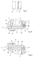
Figure 8 is a partial view in elevation and section corresponding, in enlargement, to the part ofFigure 1 which can be seen at bottom right; and - -
Figure 9 is a view similar toFigure 8 , but for the portion ofFigure 1 which is seen at top right. - The filter cartridge 1 illustrated in
Figure 1 comprises asheath 2, afiltering pack 3, acore 4, abottom end cap 5 and atop end cap 6. Here the cartridge 1 has a height of approximately 254 mm (10 inches) and an external diameter of approximately 69 mm. - The
sheath 2 is made from moulded thermoplastic, here injected polypropylene. It has a tubular shape. Through itswalls perforations 7 are formed, only some of which are depicted inFigure 1 , in order not to overload the drawing. Theperforations 7 allow the passage of a liquid through the wall of thesheath 2. - What has just been said with regard to the
sheath 2 is equally valid for thecore 4, except that the perforations provided through its wall are referenced 8. - The
core 4 has a diameter which is smaller than the diameter of thesheath 2. They are disposed concentrically, so that there exists between thesheath 2 and the core 4 atubular space 9. - The
end caps sheath 2 and thecore 4, injected polypropylene. - A portion situated along the bottom edge 33 (
Figure 8 ) of thesheath 2 is embedded in the material of thecap 5, and the same applies to thecore 4, so that thespace 9 is closed at the bottom end of the cartridge 1 by thecap 5, and more precisely by the part of the latter which extends transversely between thesheath 2 and thecore 4. - The same applies to the top edge of the
sheath 2 and the bottom edge of thecore 4 facing thecap 6, which therefore closes the top end of thechamber 9. - As can be seen more particularly in
Figure 2 , thefiltering pack 3 has overall, in cross-section, the shape of a star having a multitude of arms. - This pack is made from a flat filtering medium, folded in a zigzag and closed on itself by joining its two longitudinal ends. Here the
pack 3 has one hundred and twenty-seven folds. - Just like the
sheath 2 and thecore 4, a portion situated along the bottom edge of thepack 3 is embedded in the material of theend cap 5 and a portion situated along the top edge of thepack 3 is embedded in the material of thecap 6. - Thus the
space 9 is subdivided by thefiltering pack 3 into two chambers situated respectively on each side of this pack, one of the chambers being in communication with the outside only throughperforations 7 and the other chamber only throughperforations 8. - Consequently, a liquid entering the
space 9 throughperforations 7 will be able to emerge therefrom, through theperforations 8, only after having passed through thefiltering pack 3. The same applies of course for a liquid entering through theperforations 8 and leaving through theperforations 7. - The arrangement of the
filtering medium 10 which with thepack 3 is made will now be described with the help ofFigure 3 . - The medium 10 has a
filtering membrane 11, here made from polyvinylidene fluoride (PVDF), athermoplastic ribbon 12, here made from polypropylene, disposed in the vicinity of eachedge 13 of themembrane 11, and, on each side of themembrane 11 provided with theribbon 12, a respectivelylayer layers filtering medium 10 to have a certain resistance to tearing. - Each
ribbon 12 is applied to themembrane 11 whilst approximately 70% of its width, as from its edge situated on the side of theedge 13, is heated, and is therefore welded to themembrane 11. In the example illustrated, the edges of themembrane 11 and of theribbon 12 are flush with each other, theribbon 12 is welded to themembrane 11 over 7.5 to 8 mm as from theedge 13 whilst theribbon 12 is in simple contact with themembrane 11 over the rest of its width, that is to say approximately 3 mm. - The
layers membrane 11 and theribbons 12. - The width of the
layers membrane 13, so that therespective edges layers edge 13. Here the distance between theedge 13 and the edge of thelayers - The
layer 14A, which is situated, with respect to themembrane 11, on the same side as theribbon 12, is situated, in thefiltering assembly 3, on the outside, that is to say on the side of thesheath 2, whilst thelayer 14B is on the inside, that is to say on the side of thecore 4. - In the example illustrated, provision is made for the liquid to be filtered to enter the
space 9 through theperforations 7 in thesheath 2 and leaves it through theperforations 8 in thecore 4. - The
layer 14A is thus on the upstream side of thefiltering medium 10 and thelayer 14B on the downstream side. - It should be noted that, in
Figure 3 , in order to simplify the drawing, themembrane 11, theribbon 12 and thelayers membrane 11 is thicker than theribbon 12 and less thick than thelayers membrane 11 has a thickness of 100 to 150 µm, theribbon 12 has a thickness of approximately 50 µm and thelayers - The
bottom end cap 5 will now described with the help ofFigures 4 and 5 . - As indicated above, this cap is made from thermoplastic, and more precisely polypropylene, injection moulded.
- Even more precisely, the
cap 5 is moulded by bi-injection. It has afirst disc 16 made from a first grade of polypropylene and formed in a first injection operation, and has asecond disc 17, made from another grade of polypropylene and moulded onto thefirst disc 16 in a second injection operation. - As can be seen more particularly in
Figure 5 , thefirst disc 16 has a flatcircular plate 18. On the side which can be seen at the top of the drawings, that is to say on the side which will be turned towards the inside of the cartridge 1, aperipheral rim 19 extends projecting from theplate 18. Here this rim is interrupted at regular intervals, with the segments of therim 19 forming steps separated from each other bycrenulations 20. There are more precisely here four crenulations regularly distributed from an angular point of view, each extending over an arc whose angle at the apex is approximately 30°. - On the side which can be seen at the bottom in the drawings, that is to say on the side designed to be situated outside the cartridge 1, the
first disc 16 has aannular rib 21 whose diameter is approximately equal to two thirds of the diameter of thefirst disc 16. - It should be noted that the
first disc 16 is shown alone inFigure 5 in order to give a clear understanding of the invention but that in practice thedisc 16 is not removed from the mould as it stands: when the two half-moulds which have been used for obtaining thedisc 16 are separated, the latter remains in the half-mould situated on the bottom side whilst another top half-mould is substituted for the half-mould which was situated on the top side, the hollow existing between thedisc 16 and the second top mould having the shape of thesecond disc 17, which is then formed by injecting the second grade of polypropylene into this hollow. - It should be noted that the
crenulations 20 serve as a vent making it possible to perform the second injection by means of which thedisc 17 is formed by moulding onto thedisc 16. - As can be seen in
Figure 6 , thetop end cap 6 is identical to thebottom cap 5, except that it has acentral orifice 22, and except that the rib situated on the external side has a different profile. For the components of thecap 6 which are similar to those of thecap 5, the present document employs the same numerical references, but allocated a prime index. - Whilst the
rib 21 is directly bordered, towards the centre, by a shoulder, the rib 21' is bordered, towards the centre, by agroove 23 useful, after assembly of the cartridge 1, for the fixing of a connecting piece. Around theorifice 22, the disc 16' has arim 19A. Whilst the edge of therims 19 or 19' is flush with the surface of thedisc 17 or 17', the edge of therim 19A is covered by the disc 17'. - It will now be explained how the filter cartridge 1 is assembled.
- A
bottom end cap 5 and atop end cap 6 are placed respectively in thesupport 25 and in the support 26 (Figure 2 ), which each have for this purpose a hollow having the same contour as the cap, as can be seen inFigure 7 for thesupport 25 and thecap 5, with the face designed to be towards the inside of the cartridge 1, which remains free. - The heating blocks 27 and 28 are then placed respectively in front of the
support 25 and in front of thesupport 26, so that the surface of thecaps blocks arrows 30 inFigure 2 . - The heating is continued until the aforementioned surface reaches a predetermined threshold temperature, for example situated between 250 and 270°C.
- The heating blocks 27 and 28 are then withdrawn, the precartridge 31 formed by the
sheath 2, thepack 3 and thecore 4 slipped in one another are placed in alignment with thesupports supports end caps - The contact force exerted has the effect of making a portion situated along the edge respectively of the
sheath 2, thepack 3 and thecore 4 penetrate the material, softened by heating, of each of theend caps Figure 8 for thebottom end cap 5 and inFigure 9 for thetop end cap 6. - As can be seen clearly in the latter figures, it is more precisely in the
disc 17 and in the disc 17' that the respective portions of the various constituents of the precartridge 31 are thus embedded. - The
first disc 16 or 16' respectively of theend cap 5 and of theend cap 6 is made from a polypropylene whose melt flow rate is relatively low, typically from 5.2 g per 10 minutes at 230°C and at 2.16 kg, according to the ASTM D1238 or ISO 1133 test method, for example such a rate lying between 4.2 and 6.5 g per 10 minutes, or even less than 15 g per 10 minutes. - It is here a homopolymer polypropylene sold under the name Escorene PP 1052 by Exxon Corporation (names belonging to their owners).
- On the other hand, the polypropylene from which the
second disc 17 or 17' respectively of thecap 5 andcap 6 are made has a relatively high melt flow rate, typically 70 g per 10 minutes according to the above mentioned test methods, for example such a rate between 65 and 75 g per 10 minutes, or even between 15 and 100 g per 10 minutes. - It is here the copolymer polypropylene sold under the name Inspire C711-70RNA from Dow Plastics (names belonging to their owners).
- The thermoplastic from which the
discs 16 and 16' are made, whose melt flow rate hot is, as has just been seen, much less high than that of the thermoplastic from which thediscs 17 and 17' are made, also has better impact resistance, from which theend caps discs 17 and 17'. - The rotation movement of the
supports Figure 2 by thearrows 30, prevents, or in any case reduces, the phenomena of gravity flow of the material of thecaps - By virtue of the relatively high fluidity when hot of the
second discs 17 and 17', the penetration of the portions situated along the edges of the various constituents of the precartridge 31 is effected excellently. - The
sheath 2, in this regard, has, at each of its ends, aneck 32 thinner than the rest of its wall. - As can be seen in
Figure 8 , theneck 32 is situated between theedge 33 of thesheath 2 and ashoulder 34 on this sheath, a shoulder which has substantially the same width as theedge 35 of therim 19 or 19'. Theshoulder 34 extends between the general external surface of thesheath 2 and afrustoconical surface 36 extending itself from theshoulder 34 to theedge 33, the latter extending from thesurface 36 to an internal surface situated in continuity with the general internal surface of thesheath 2. - The orientation of the slope of the
surface 36 is such that the thickness of theneck 32 decreases between theshoulder 34 and theedge 33. - The
rim 19 or 19' has a profile complementary to that of theneck 32, its internallateral surface 37 being frustoconical and similar to thesurface 36, itsedge 35 being similar to theshoulder 34 whilst its external lateral surface is cylindrical and has substantially the same diameter as the general external surface of thesheath 2. - The
core 4 also has a neck at each of its ends, referenced 38 in the drawings, this neck here being simply formed, as can be seen inFigure 8 , by afrustoconical surface 39 extending from theedge 40 of thecore 4 to its external lateral surface (the surface facing the chamber 9), the slope of thesurface 39 being substantially the same as that of thesurfaces - In the example illustrated, the
second discs 17 and 17' typically have a thickness of 2.6 mm. Provision is made for the distance between theplate 18 or 18' of thefirst disc 16 or 16' and the edge of the various constituents of the precartridge 31 to be typically 0.6 mm for thesheath 2, 0.7 mm for thefiltering pack 3 and 1.2 mm for thecore 4. - With regard more particularly to the
flat filtering medium 10, having regard to the values indicated above, its depth of penetration into thedisc 17 or 17' is on average around 1.9 mm. - The relative ease of penetration due to the high fluidity when hot of the
disc 17 or 17' offers the advantage of avoiding, on the occasion of the penetration into the end caps, the appearance, in thefiltering medium 10, of stresses concentrated in some cases to a relatively great extent in the vicinity of the end caps, with the consequence of this concentration of stresses that the two respective zones of the medium 10 adjacent to the end caps would be weakened, and in particular would be subject to rupture by shearing under the effect of the pressure difference existing on each side of the medium 10 when the cartridge 1 is functioning. - It should be noted in particular, with regard to the reasons why the concentrations of stresses were avoided by virtue of the relative ease of penetration of the
filtering medium 10 into the end caps, that, on the one hand, it suffices to exert, in order to effect this penetration, a very low force of bringing thecaps caps disc 16 and 16', the low intensity of the bringing-together force exerted here between thecaps filtering pack 3 take a curved shape, from which the result would be that the two adjacent respective regions of the edges of the medium 10 would have a tendency to fit in the end caps aslant, and, on the other hand, avoiding making the regions of the medium 10 adjacent to its respective edges that fold, at the time of penetration, through a buckling mechanism. - Thus the two adjacent regions of the respective edges of the medium 10, embedded in the
cap 5 and in thecap 6, remain overall oriented in the axial direction. The result is an effective setting both of thelayer 14A and of thelayer 14B in the material of thecaps - This is because each of the
layers filtering medium 10, here fully fulfils its role of reinforcement, both when the flow of the liquid to be filtered takes place in the nominal direction, that is to say in the direction in which the liquid circulates from theperforations 7 in thesheath 2 towards theperforations 8 in the core 4 (the highest pressure is then situated on the side of thelayer 14A), than in the case of a circulation in the opposite direction (the highest pressure then being situated on the side of thelayer 14B). - For each of the
end caps discs - In a variant which is not shown, the
core 4 is replaced by a core which is free with respect to theend caps - In another variant which is not shown, the
rim 19 has more than four crenulations or interruptions, or has no interruption and is therefore continuous. - In other variants which are not shown, only one of the
end caps - More generally, the invention is not limited to the examples described and depicted.
Claims (36)
- Filtering cartridge comprising:- a filtering pack (3) formed from a flat filtering medium (10);- a tubular sheath (2) with a perforated wall, surrounding said filtering pack (3) so that there is a chamber between the filtering pack (3) and the tubular sheath (2); and- two respective thermoplastic end caps (5, 6), in each of which there is embedded a portion of said filtering pack (3) situated along one of its edges, and in each of which there is embedded a portion of said sheath (2) situated along one of its edges (33);characterised in that:- at least one said end cap (5, 6) has a first disc (16, 16') and a second disc (17, 17'), placed one above the other, each made from thermoplastic;- it is in the said second disc (17, 17') that the said portion of the filtering pack (3) and the said sheath portion (2) are embedded;- the said first disc (16, 16') has a peripheral rim (19, 19') which surrounds the said portion of the sheath (2); and- the said sheath (2) has a shoulder (34) opposite the edge of the said rim (19,19') of the first disc (16,16').
- Cartridge according to Claim 1, characterised in that said portion of the sheath (2) forms part of a neck (32) thinner than the rest of the wall of the sheath (2).
- Cartridge according to Claim 2, characterised in that said neck (32) has a thickness which increases as from the edge (33) of the sheath (2).
- Cartridge according to either one of Claims 2 or 3, characterised in that said neck (32) is situated between the edge (33) and said shoulder (34) of the sheath (2).
- Cartridge according to Claim 4, characterised in that the edge (33) of the sheath (2) extends from an internal surface, situated in continuity with the general internal surface of the sheath (2), to a frustoconical surface (36) which extends from the edge (33) to said shoulder (34), which extends from said frustoconical surface (36) to the general external surface of the sheath (2).
- Cartridge according to any one of Claims 1 to 5, characterised in that said rim (19, 19') of the first disc (16, 16') extends projecting from a plate (18, 18').
- Cartridge according to Claim 6, characterised in that the thickness of said rim (19, 19') increases as from its edge (35).
- Cartridge according to Claim 7, characterised in that the edge of said rim (19, 19') extends from an external lateral surface, having substantially the same diameter as the general external surface of the sheath (2), to a frustoconical surface extending from this rim to said plate (18, 18').
- Cartridge according to any one of Claims 1 to 8, characterised in that said shoulder (34) on the sheath (2) and the edge (35) of said rim (19, 19') has substantially the same width.
- Cartridge according to any one of Claims 1 to 9, characterised in that said rim (19, 19') faces said portion of the sheath (2) embedded in the second disc (17, 17') through a surface (37) which is frustoconical.
- Cartridge according to any one of Claims 1 to 10, characterised in that said portion of the sheath (2) embedded in the second disc (17, 17') faces said rim (19, 19') through a surface (36) which is frustoconical.
- Cartridge according to any one of Claims 1 to 11, characterised in that said portion of the sheath (2) embedded in the second disc (17, 17') and said rim (19, 19') face each other through a respective frustoconical surface (36, 37), said respective frustoconical surfaces (36, 37) being similar.
- Cartridge according to any one of Claims 1 to 12, characterised in that said rim (19, 19') has interruptions (20).
- Cartridge according to Claim 13, characterised in that said interruptions (20) are disposed at regular intervals and each extend over an arc with the same angle at the apex.
- Cartridge according to Claim 14, characterised in that said rim (19, 19') has four said interruptions (20) each extending over an arc whose angle at the apex is approximately 30°.
- Cartridge according to any one of Claims 1 to 15, characterised in that said first disc (16, 16') has, opposite to said second disc (17, 17'), an annular rib (21, 21').
- Cartridge according to any one of Claims 1 to 16, characterised in that at least one said end cap (6) having a first disc (16') and a second disc (17') placed one above the other, has a central orifice (22).
- Cartridge according to Claim 17, characterised in that the first disc (16') of the cap (6) having a central orifice (22), has a rim (19A) around said central orifice (22).
- Cartridge according to any one of Claims 1 to 18, characterised in that it also comprises a tubular core (4) with a perforated wall, surrounded by said filtering pack (3) and having, along at least one edge (40), a portion embedded in said second disc (17, 17').
- Cartridge according Claim 19, characterised in that each said portion of the core (4) forms part of a neck (38) which is thinner than the rest of the core (4).
- Cartridge according to Claim 20, characterised in that the edge (40) of the core (4) extends from an internal surface, situated in continuity with the general internal surface of the core (2) to a frustoconical surface (39) which extends from the edge (40) to the general external surface of the core (4).
- Cartridge according to any one of Claims 1 to 21, characterised in that the melt flow rate at 230°C and under 2.16 kg, according to the ASTM D1238 or ISO 1133 test method, is lower for the material of the first disc (16, 16') than for the material of the second disc (17, 17').
- Cartridge according to Claim 22, characterised in that said melt flow rate is no more than 15 g per 10 minutes for the material of the first disc (16, 16').
- Cartridge according to Claim 23, characterised in that said melt flow rate of the first disc (16, 16') is between 4.2 and 6.5 g per 10 minutes.
- Cartridge according to any one of Claims 22 to 24, characterised in that said melt flow rate of the second disc (17, 17') is between 25 and 100 g per 10 minutes.
- Cartridge according to Claim 25, characterised in that said melt flow rate of the second disc (17, 17') is between 65 and 75 g per 10 minutes.
- Cartridge according to any one of Claims 1 to 26, characterised in that said end cap (5, 6) comprising a first disc (16, 16') and a second disc (17, 17') is moulded by bi-injection.
- Cartridge according to Claim 27, characterised in that said second disc (17, 17') is moulded onto said first disc (16,16').
- Cartridge according to any one of Claims 1 to 28, characterised in that said first disc (16, 16') and said second disc (17, 17') are made from polypropylene.
- Cartridge according to Claim 29, characterised in that said first disc (16, 16') is made from a homopolymer polypropylene whilst the second disc (17, 17') is made from a copolymer polypropylene.
- Cartridge according to any one of Claims 1 to 30, characterised in that said flat filtering medium (10) forming said filtering pack (3) comprises a filtering membrane (11) and two support layers (14A, 14B) sandwiching said membrane.
- Cartridge according to Claim 31, characterised in that said filtering medium (10) also comprises a thermoplastic ribbon (12) disposed in the vicinity of each edge (13) of said membrane (11).
- Cartridge according to either one of Claims 31 or 32, characterised in that said membrane is made from polyvinylidene fluoride (PVDF).
- Cartridge according to any one of Claims 31 to 33, characterised in that said support layers are made from thermoplastic.
- Cartridge according to any one of Claims 31 to 34, characterised in that said layers (14A, 14B) and a thermoplastic ribbon (12) disposed in the vicinity of each edge (13) of said membrane (11) are made from polypropylene.
- Cartridge according to any one of Claims 31 to 35, characterised in that each said end cap (5, 6) has a said first disc (16, 16') and a said second disc (17, 17'), and cooperates in a similar fashion with the sheath (2) and the filtering pack (3).
Applications Claiming Priority (3)
| Application Number | Priority Date | Filing Date | Title |
|---|---|---|---|
| FR0208415A FR2841795B1 (en) | 2002-07-04 | 2002-07-04 | FILTER CARTRIDGE |
| FR0208415 | 2002-07-04 | ||
| PCT/EP2003/006911 WO2004004864A1 (en) | 2002-07-04 | 2003-06-30 | Filter cartridge |
Publications (2)
| Publication Number | Publication Date |
|---|---|
| EP1519778A1 EP1519778A1 (en) | 2005-04-06 |
| EP1519778B1 true EP1519778B1 (en) | 2008-11-05 |
Family
ID=29725175
Family Applications (1)
| Application Number | Title | Priority Date | Filing Date |
|---|---|---|---|
| EP03762552A Expired - Lifetime EP1519778B1 (en) | 2002-07-04 | 2003-06-30 | Filter cartridge |
Country Status (8)
| Country | Link |
|---|---|
| US (1) | US7389883B2 (en) |
| EP (1) | EP1519778B1 (en) |
| JP (2) | JP4794165B2 (en) |
| AT (1) | ATE413220T1 (en) |
| DE (1) | DE60324558D1 (en) |
| ES (1) | ES2316815T3 (en) |
| FR (1) | FR2841795B1 (en) |
| WO (1) | WO2004004864A1 (en) |
Families Citing this family (7)
| Publication number | Priority date | Publication date | Assignee | Title |
|---|---|---|---|---|
| EP2279782B1 (en) | 2004-12-23 | 2014-08-13 | EMD Millipore Corporation | Filter cartridge |
| DE102005008935A1 (en) * | 2005-02-26 | 2006-08-31 | Mann + Hummel Gmbh | plastic end |
| DE102007013178A1 (en) * | 2007-03-20 | 2008-09-25 | Hydac Filtertechnik Gmbh | Method for producing a filter element and filter element produced by the method |
| DE102008049627A1 (en) * | 2008-09-30 | 2010-04-08 | Mann + Hummel Gmbh | Method for producing a filter end disk and a fluid filter, motor vehicle fluid filter |
| JP5555297B2 (en) * | 2012-10-04 | 2014-07-23 | 株式会社ウェルシィ | Portable water purification kit |
| US9737855B2 (en) * | 2014-06-17 | 2017-08-22 | W. L. Gore & Associates, Inc. | Filtration article containing a filtration material containing fibrous layers having different lengths |
| JP6659233B2 (en) * | 2015-04-22 | 2020-03-04 | ヤマシンフィルタ株式会社 | Filter element and filter device |
Citations (1)
| Publication number | Priority date | Publication date | Assignee | Title |
|---|---|---|---|---|
| WO2000044485A2 (en) * | 1999-01-29 | 2000-08-03 | Millipore Corporation | Perfluorinated thermoplastic filter cartridge |
Family Cites Families (21)
| Publication number | Priority date | Publication date | Assignee | Title |
|---|---|---|---|---|
| US3457339A (en) * | 1965-12-08 | 1969-07-22 | Pall Corp | Process for making end capped filter elements |
| BE757121A (en) * | 1969-10-06 | 1971-03-16 | Fram Filters Ltd | FILTER ELEMENTS |
| US3933557A (en) * | 1973-08-31 | 1976-01-20 | Pall Corporation | Continuous production of nonwoven webs from thermoplastic fibers and products |
| US4032688A (en) * | 1973-08-31 | 1977-06-28 | Pall Corporation | Seamless tubular nonwoven webs and filters thereof |
| US4231768A (en) * | 1978-09-29 | 1980-11-04 | Pall Corporation | Air purification system and process |
| US4228012A (en) * | 1978-10-26 | 1980-10-14 | Pall Corporation | End cap coupler system for linking one filter cartridge to another filter cartridge or functional member |
| US4521309A (en) * | 1980-07-14 | 1985-06-04 | Pall Corporation | Filter cartridge with castellated support and process of making the same |
| DE3277497D1 (en) * | 1981-04-14 | 1987-11-26 | Pall Corp | Polymer filter cartridge of glass fibers coated with fluoroethylene polymer and process for preparing the same |
| US4579698A (en) * | 1982-05-28 | 1986-04-01 | Amf, Inc. | Process for producing a microporous polymeric filter membrane with adjacent non-porous edge layers and a pleated filter element formed from the membrane |
| DE3318940A1 (en) * | 1983-05-25 | 1984-11-29 | Sartorius GmbH, 3400 Göttingen | TUBULAR FILTER ELEMENT |
| JPS61200108U (en) * | 1985-05-31 | 1986-12-15 | ||
| JPH0713785Y2 (en) * | 1986-11-29 | 1995-04-05 | 株式会社土屋製作所 | Filter element |
| JPH0817923B2 (en) * | 1987-03-31 | 1996-02-28 | 株式会社 土屋製作所 | Method for manufacturing synthetic resin filter element |
| GB8808890D0 (en) * | 1988-04-15 | 1988-05-18 | Grace W R & Co | Container closure caps & compositions for forming gaskets for them |
| JPH05111622A (en) * | 1991-10-23 | 1993-05-07 | Nippon Millipore Kogyo Kk | Production of filter element |
| JP3144858B2 (en) * | 1991-11-06 | 2001-03-12 | 株式会社ロキテクノ | Manufacturing method of precision membrane pleated filter cartridge |
| US5685443A (en) * | 1995-03-06 | 1997-11-11 | White Cap, Inc. | Composite closure and method of making same |
| DE19543955C2 (en) * | 1995-11-25 | 1998-12-24 | Sartorius Gmbh | Integrity testable filtration unit with hydrophilic, porous membranes |
| DE19919289A1 (en) * | 1999-04-28 | 2000-11-02 | Mahle Filtersysteme Gmbh | Forming sealed plastic closure on end edges of zig-zag folded strip of filter, especially ring filter, comprises melting one layer containing inductively heatable particles |
| IT1311066B1 (en) * | 1999-12-23 | 2002-02-28 | Sacmi | METHOD FOR DECORATING THE SUMMIT OF A CLOSING CAP OF A RECIPIENT. |
| JP4671974B2 (en) * | 2007-01-05 | 2011-04-20 | 株式会社マーレ フィルターシステムズ | Filter cartridge |
-
2002
- 2002-07-04 FR FR0208415A patent/FR2841795B1/en not_active Expired - Fee Related
-
2003
- 2003-06-30 WO PCT/EP2003/006911 patent/WO2004004864A1/en not_active Ceased
- 2003-06-30 EP EP03762552A patent/EP1519778B1/en not_active Expired - Lifetime
- 2003-06-30 DE DE60324558T patent/DE60324558D1/en not_active Expired - Lifetime
- 2003-06-30 AT AT03762552T patent/ATE413220T1/en not_active IP Right Cessation
- 2003-06-30 ES ES03762552T patent/ES2316815T3/en not_active Expired - Lifetime
- 2003-06-30 JP JP2004518629A patent/JP4794165B2/en not_active Expired - Lifetime
- 2003-06-30 US US10/517,461 patent/US7389883B2/en not_active Expired - Lifetime
-
2010
- 2010-09-30 JP JP2010220982A patent/JP5179552B2/en not_active Expired - Lifetime
Patent Citations (1)
| Publication number | Priority date | Publication date | Assignee | Title |
|---|---|---|---|---|
| WO2000044485A2 (en) * | 1999-01-29 | 2000-08-03 | Millipore Corporation | Perfluorinated thermoplastic filter cartridge |
Also Published As
| Publication number | Publication date |
|---|---|
| US7389883B2 (en) | 2008-06-24 |
| US20060016746A1 (en) | 2006-01-26 |
| JP2005531402A (en) | 2005-10-20 |
| ES2316815T3 (en) | 2009-04-16 |
| JP5179552B2 (en) | 2013-04-10 |
| ATE413220T1 (en) | 2008-11-15 |
| JP2011000591A (en) | 2011-01-06 |
| DE60324558D1 (en) | 2008-12-18 |
| JP4794165B2 (en) | 2011-10-19 |
| FR2841795B1 (en) | 2004-09-24 |
| FR2841795A1 (en) | 2004-01-09 |
| EP1519778A1 (en) | 2005-04-06 |
| WO2004004864A1 (en) | 2004-01-15 |
Similar Documents
| Publication | Publication Date | Title |
|---|---|---|
| US20240375055A1 (en) | Features on a porous membrane | |
| EP0181366B1 (en) | Improvements in and relating to filters | |
| US6524411B2 (en) | Method of applying an end-cap to a pleated filter element | |
| DE2353610A1 (en) | END CAP WITH AT LEAST ONE CIRCLING GROOVE, IN PARTICULAR FOR COVERING A TUBULAR FILTER ELEMENT, METHOD FOR PRODUCING SUCH END CAP AND CONNECTING THE END CAP TO THE FILTER ELEMENT | |
| US6739459B1 (en) | Filter element including bonded end caps and support core | |
| EP0856346A1 (en) | Improved pleated filter arrangement | |
| US4865738A (en) | Filter cartridge with truncated sawtooth projection assembly | |
| CA2072532A1 (en) | Filter assembly with a spin welded end cap | |
| US7389883B2 (en) | Filter cartridge | |
| US7828155B2 (en) | Thermoplastic injection molding method for capping a tubular filtration medium | |
| AU761946B2 (en) | Filter element and method of making a filter element | |
| CA1169363A (en) | Filter cartridge with castellated support and process of making the same | |
| EP0062867A2 (en) | Polymer filter cartridge of glass fibers coated with fluoroethylene polymer and process for preparing the same | |
| AU2004202736A1 (en) | Graded Particle-size Retention Filter Medium for Cell-type Filter Unit | |
| US20050016916A1 (en) | Mechanical interlock for filters | |
| JP3775267B2 (en) | Air cleaner element pleat contact prevention member and air cleaner element | |
| US20040118766A1 (en) | Graded particle-size retention filter medium for cell-type filter unit |
Legal Events
| Date | Code | Title | Description |
|---|---|---|---|
| PUAI | Public reference made under article 153(3) epc to a published international application that has entered the european phase |
Free format text: ORIGINAL CODE: 0009012 |
|
| 17P | Request for examination filed |
Effective date: 20050103 |
|
| AK | Designated contracting states |
Kind code of ref document: A1 Designated state(s): AT BE BG CH CY CZ DE DK EE ES FI FR GB GR HU IE IT LI LU MC NL PT RO SE SI SK TR |
|
| 17Q | First examination report despatched |
Effective date: 20070111 |
|
| GRAP | Despatch of communication of intention to grant a patent |
Free format text: ORIGINAL CODE: EPIDOSNIGR1 |
|
| GRAS | Grant fee paid |
Free format text: ORIGINAL CODE: EPIDOSNIGR3 |
|
| GRAA | (expected) grant |
Free format text: ORIGINAL CODE: 0009210 |
|
| AK | Designated contracting states |
Kind code of ref document: B1 Designated state(s): AT BE BG CH CY CZ DE DK EE ES FI FR GB GR HU IE IT LI LU MC NL PT RO SE SI SK TR |
|
| REG | Reference to a national code |
Ref country code: GB Ref legal event code: FG4D |
|
| REG | Reference to a national code |
Ref country code: CH Ref legal event code: EP |
|
| REG | Reference to a national code |
Ref country code: IE Ref legal event code: FG4D |
|
| REF | Corresponds to: |
Ref document number: 60324558 Country of ref document: DE Date of ref document: 20081218 Kind code of ref document: P |
|
| REG | Reference to a national code |
Ref country code: CH Ref legal event code: NV Representative=s name: KIRKER & CIE S.A. |
|
| REG | Reference to a national code |
Ref country code: ES Ref legal event code: FG2A Ref document number: 2316815 Country of ref document: ES Kind code of ref document: T3 |
|
| PG25 | Lapsed in a contracting state [announced via postgrant information from national office to epo] |
Ref country code: AT Free format text: LAPSE BECAUSE OF FAILURE TO SUBMIT A TRANSLATION OF THE DESCRIPTION OR TO PAY THE FEE WITHIN THE PRESCRIBED TIME-LIMIT Effective date: 20081105 |
|
| PG25 | Lapsed in a contracting state [announced via postgrant information from national office to epo] |
Ref country code: SI Free format text: LAPSE BECAUSE OF FAILURE TO SUBMIT A TRANSLATION OF THE DESCRIPTION OR TO PAY THE FEE WITHIN THE PRESCRIBED TIME-LIMIT Effective date: 20081105 Ref country code: FI Free format text: LAPSE BECAUSE OF FAILURE TO SUBMIT A TRANSLATION OF THE DESCRIPTION OR TO PAY THE FEE WITHIN THE PRESCRIBED TIME-LIMIT Effective date: 20081105 |
|
| PG25 | Lapsed in a contracting state [announced via postgrant information from national office to epo] |
Ref country code: EE Free format text: LAPSE BECAUSE OF FAILURE TO SUBMIT A TRANSLATION OF THE DESCRIPTION OR TO PAY THE FEE WITHIN THE PRESCRIBED TIME-LIMIT Effective date: 20081105 Ref country code: BG Free format text: LAPSE BECAUSE OF FAILURE TO SUBMIT A TRANSLATION OF THE DESCRIPTION OR TO PAY THE FEE WITHIN THE PRESCRIBED TIME-LIMIT Effective date: 20090205 Ref country code: RO Free format text: LAPSE BECAUSE OF FAILURE TO SUBMIT A TRANSLATION OF THE DESCRIPTION OR TO PAY THE FEE WITHIN THE PRESCRIBED TIME-LIMIT Effective date: 20081105 Ref country code: DK Free format text: LAPSE BECAUSE OF FAILURE TO SUBMIT A TRANSLATION OF THE DESCRIPTION OR TO PAY THE FEE WITHIN THE PRESCRIBED TIME-LIMIT Effective date: 20081105 |
|
| PG25 | Lapsed in a contracting state [announced via postgrant information from national office to epo] |
Ref country code: PT Free format text: LAPSE BECAUSE OF FAILURE TO SUBMIT A TRANSLATION OF THE DESCRIPTION OR TO PAY THE FEE WITHIN THE PRESCRIBED TIME-LIMIT Effective date: 20090406 Ref country code: CZ Free format text: LAPSE BECAUSE OF FAILURE TO SUBMIT A TRANSLATION OF THE DESCRIPTION OR TO PAY THE FEE WITHIN THE PRESCRIBED TIME-LIMIT Effective date: 20081105 Ref country code: SE Free format text: LAPSE BECAUSE OF FAILURE TO SUBMIT A TRANSLATION OF THE DESCRIPTION OR TO PAY THE FEE WITHIN THE PRESCRIBED TIME-LIMIT Effective date: 20090205 |
|
| PLBE | No opposition filed within time limit |
Free format text: ORIGINAL CODE: 0009261 |
|
| STAA | Information on the status of an ep patent application or granted ep patent |
Free format text: STATUS: NO OPPOSITION FILED WITHIN TIME LIMIT |
|
| PG25 | Lapsed in a contracting state [announced via postgrant information from national office to epo] |
Ref country code: SK Free format text: LAPSE BECAUSE OF FAILURE TO SUBMIT A TRANSLATION OF THE DESCRIPTION OR TO PAY THE FEE WITHIN THE PRESCRIBED TIME-LIMIT Effective date: 20081105 |
|
| 26N | No opposition filed |
Effective date: 20090806 |
|
| PG25 | Lapsed in a contracting state [announced via postgrant information from national office to epo] |
Ref country code: MC Free format text: LAPSE BECAUSE OF NON-PAYMENT OF DUE FEES Effective date: 20090630 |
|
| REG | Reference to a national code |
Ref country code: IE Ref legal event code: MM4A |
|
| PG25 | Lapsed in a contracting state [announced via postgrant information from national office to epo] |
Ref country code: IE Free format text: LAPSE BECAUSE OF NON-PAYMENT OF DUE FEES Effective date: 20090630 |
|
| PG25 | Lapsed in a contracting state [announced via postgrant information from national office to epo] |
Ref country code: GR Free format text: LAPSE BECAUSE OF FAILURE TO SUBMIT A TRANSLATION OF THE DESCRIPTION OR TO PAY THE FEE WITHIN THE PRESCRIBED TIME-LIMIT Effective date: 20090206 |
|
| PG25 | Lapsed in a contracting state [announced via postgrant information from national office to epo] |
Ref country code: IT Free format text: LAPSE BECAUSE OF FAILURE TO SUBMIT A TRANSLATION OF THE DESCRIPTION OR TO PAY THE FEE WITHIN THE PRESCRIBED TIME-LIMIT Effective date: 20081105 |
|
| PG25 | Lapsed in a contracting state [announced via postgrant information from national office to epo] |
Ref country code: LU Free format text: LAPSE BECAUSE OF NON-PAYMENT OF DUE FEES Effective date: 20090630 |
|
| PG25 | Lapsed in a contracting state [announced via postgrant information from national office to epo] |
Ref country code: HU Free format text: LAPSE BECAUSE OF FAILURE TO SUBMIT A TRANSLATION OF THE DESCRIPTION OR TO PAY THE FEE WITHIN THE PRESCRIBED TIME-LIMIT Effective date: 20090506 |
|
| PG25 | Lapsed in a contracting state [announced via postgrant information from national office to epo] |
Ref country code: TR Free format text: LAPSE BECAUSE OF FAILURE TO SUBMIT A TRANSLATION OF THE DESCRIPTION OR TO PAY THE FEE WITHIN THE PRESCRIBED TIME-LIMIT Effective date: 20081105 |
|
| PG25 | Lapsed in a contracting state [announced via postgrant information from national office to epo] |
Ref country code: CY Free format text: LAPSE BECAUSE OF FAILURE TO SUBMIT A TRANSLATION OF THE DESCRIPTION OR TO PAY THE FEE WITHIN THE PRESCRIBED TIME-LIMIT Effective date: 20081105 |
|
| REG | Reference to a national code |
Ref country code: CH Ref legal event code: PFA Owner name: EMD MILLIPORE CORPORATION Free format text: MILLIPORE CORPORATION#290 CONCORD ROAD#BILLERICA, MASSACHUSETTS 01821-3405 (US) -TRANSFER TO- EMD MILLIPORE CORPORATION#290 CONCORD ROAD#BILLERICA, MA 01821 (US) |
|
| REG | Reference to a national code |
Ref country code: NL Ref legal event code: TD Effective date: 20120227 |
|
| REG | Reference to a national code |
Ref country code: ES Ref legal event code: PC2A Owner name: EMD MILLIPORE CORPORATION Effective date: 20120416 |
|
| REG | Reference to a national code |
Ref country code: FR Ref legal event code: CD Owner name: EMD MILLIPORE CORPORATION Effective date: 20120327 |
|
| REG | Reference to a national code |
Ref country code: DE Ref legal event code: R082 Ref document number: 60324558 Country of ref document: DE Representative=s name: HENKEL, BREUER & PARTNER, DE |
|
| REG | Reference to a national code |
Ref country code: DE Ref legal event code: R081 Ref document number: 60324558 Country of ref document: DE Owner name: EMD MILLIPORE CORPORATION, BILLERICA, US Free format text: FORMER OWNER: MILLIPORE CORP., BILLERICA, MASS., US Effective date: 20120613 Ref country code: DE Ref legal event code: R082 Ref document number: 60324558 Country of ref document: DE Representative=s name: PATENTANWAELTE HENKEL, BREUER & PARTNER, DE Effective date: 20120613 Ref country code: DE Ref legal event code: R082 Ref document number: 60324558 Country of ref document: DE Representative=s name: PATENTANWAELTE HENKEL, BREUER & PARTNER MBB, DE Effective date: 20120613 |
|
| REG | Reference to a national code |
Ref country code: FR Ref legal event code: PLFP Year of fee payment: 14 |
|
| REG | Reference to a national code |
Ref country code: FR Ref legal event code: PLFP Year of fee payment: 15 |
|
| REG | Reference to a national code |
Ref country code: FR Ref legal event code: PLFP Year of fee payment: 16 |
|
| PGFP | Annual fee paid to national office [announced via postgrant information from national office to epo] |
Ref country code: NL Payment date: 20220513 Year of fee payment: 20 |
|
| PGFP | Annual fee paid to national office [announced via postgrant information from national office to epo] |
Ref country code: GB Payment date: 20220512 Year of fee payment: 20 Ref country code: FR Payment date: 20220510 Year of fee payment: 20 Ref country code: DE Payment date: 20220505 Year of fee payment: 20 |
|
| PGFP | Annual fee paid to national office [announced via postgrant information from national office to epo] |
Ref country code: BE Payment date: 20220526 Year of fee payment: 20 |
|
| PGFP | Annual fee paid to national office [announced via postgrant information from national office to epo] |
Ref country code: ES Payment date: 20220701 Year of fee payment: 20 |
|
| PGFP | Annual fee paid to national office [announced via postgrant information from national office to epo] |
Ref country code: CH Payment date: 20220702 Year of fee payment: 20 |
|
| REG | Reference to a national code |
Ref country code: DE Ref legal event code: R071 Ref document number: 60324558 Country of ref document: DE Ref country code: CH Ref legal event code: PL |
|
| REG | Reference to a national code |
Ref country code: NL Ref legal event code: MK Effective date: 20230629 |
|
| REG | Reference to a national code |
Ref country code: BE Ref legal event code: MK Effective date: 20230630 |
|
| P01 | Opt-out of the competence of the unified patent court (upc) registered |
Effective date: 20230602 |
|
| REG | Reference to a national code |
Ref country code: GB Ref legal event code: PE20 Expiry date: 20230629 |
|
| REG | Reference to a national code |
Ref country code: ES Ref legal event code: FD2A Effective date: 20230726 |
|
| PG25 | Lapsed in a contracting state [announced via postgrant information from national office to epo] |
Ref country code: GB Free format text: LAPSE BECAUSE OF EXPIRATION OF PROTECTION Effective date: 20230629 Ref country code: ES Free format text: LAPSE BECAUSE OF EXPIRATION OF PROTECTION Effective date: 20230701 |