EP1519599A2 - Verfahren zur Steuerung des Schlafzeitintervalls in einem drahtlosen Breitband-Zugangskommunikationssystem - Google Patents
Verfahren zur Steuerung des Schlafzeitintervalls in einem drahtlosen Breitband-Zugangskommunikationssystem Download PDFInfo
- Publication number
- EP1519599A2 EP1519599A2 EP04018838A EP04018838A EP1519599A2 EP 1519599 A2 EP1519599 A2 EP 1519599A2 EP 04018838 A EP04018838 A EP 04018838A EP 04018838 A EP04018838 A EP 04018838A EP 1519599 A2 EP1519599 A2 EP 1519599A2
- Authority
- EP
- European Patent Office
- Prior art keywords
- sleep
- window value
- subscriber station
- sleep mode
- interval
- Prior art date
- Legal status (The legal status is an assumption and is not a legal conclusion. Google has not performed a legal analysis and makes no representation as to the accuracy of the status listed.)
- Granted
Links
Images


Classifications
-
- H—ELECTRICITY
- H04—ELECTRIC COMMUNICATION TECHNIQUE
- H04W—WIRELESS COMMUNICATION NETWORKS
- H04W52/00—Power management, e.g. Transmission Power Control [TPC] or power classes
- H04W52/02—Power saving arrangements
- H04W52/0209—Power saving arrangements in terminal devices
- H04W52/0212—Power saving arrangements in terminal devices managed by the network, e.g. network or access point is leader and terminal is follower
- H04W52/0216—Power saving arrangements in terminal devices managed by the network, e.g. network or access point is leader and terminal is follower using a pre-established activity schedule, e.g. traffic indication frame
-
- H—ELECTRICITY
- H04—ELECTRIC COMMUNICATION TECHNIQUE
- H04W—WIRELESS COMMUNICATION NETWORKS
- H04W52/00—Power management, e.g. Transmission Power Control [TPC] or power classes
- H04W52/02—Power saving arrangements
-
- H—ELECTRICITY
- H04—ELECTRIC COMMUNICATION TECHNIQUE
- H04B—TRANSMISSION
- H04B7/00—Radio transmission systems, i.e. using radiation field
- H04B7/24—Radio transmission systems, i.e. using radiation field for communication between two or more posts
- H04B7/26—Radio transmission systems, i.e. using radiation field for communication between two or more posts at least one of which is mobile
-
- H—ELECTRICITY
- H04—ELECTRIC COMMUNICATION TECHNIQUE
- H04W—WIRELESS COMMUNICATION NETWORKS
- H04W68/00—User notification, e.g. alerting and paging, for incoming communication, change of service or the like
- H04W68/02—Arrangements for increasing efficiency of notification or paging channel
-
- Y—GENERAL TAGGING OF NEW TECHNOLOGICAL DEVELOPMENTS; GENERAL TAGGING OF CROSS-SECTIONAL TECHNOLOGIES SPANNING OVER SEVERAL SECTIONS OF THE IPC; TECHNICAL SUBJECTS COVERED BY FORMER USPC CROSS-REFERENCE ART COLLECTIONS [XRACs] AND DIGESTS
- Y02—TECHNOLOGIES OR APPLICATIONS FOR MITIGATION OR ADAPTATION AGAINST CLIMATE CHANGE
- Y02D—CLIMATE CHANGE MITIGATION TECHNOLOGIES IN INFORMATION AND COMMUNICATION TECHNOLOGIES [ICT], I.E. INFORMATION AND COMMUNICATION TECHNOLOGIES AIMING AT THE REDUCTION OF THEIR OWN ENERGY USE
- Y02D30/00—Reducing energy consumption in communication networks
- Y02D30/70—Reducing energy consumption in communication networks in wireless communication networks
Definitions
- the present invention relates to a broadband wireless access communication system, and more particularly to a method and an apparatus for controlling a sleep mode and an awake mode in a broadband wireless access communication system using an orthogonal frequency division multiplexing method.
- the 4th generation (hereinafter, referred to as '4G') communication system which is a next generation communication system, is being actively developed in order to provide services having different Quality of Service (hereinafter, referred to as 'QoS') levels.
- the transmission rate of the 4G communication system is about 100 Mbps.
- the 3rd generation (hereinafter, referred to as '3G') communication system usually provides a transmission speed of about 384 kbps under an outdoor channel environment which is a relatively-inferior channel environment and provides a transmission speed of about 2Mbps under an indoor channel environment which is a relatively-superior channel environment.
- a wireless local area network (hereinafter, referred to as 'LAN') system and a wireless metropolitan area network (hereinafter, referred to as 'MAN') system generally provides transmission speeds of about 20Mbps to 50Mbps.
- a new communication system which is achieved by supplementing the wireless LAN and MAN systems to combine a relatively-high transmission speed with mobility and QoS, has been developed in the current 4G communication system.
- the wireless MAN system is suitable for high-speed communication services because it has a wide service coverage area and provides a high transmission speed. However, since the wireless MAN system can not compensate for the mobility of a subscriber station SS, handoff techniques are not being considered in the wireless MAN system.
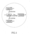
- FIG 1 is a diagram illustrating a structure of a broadband wireless access communication system using orthogonal frequency division multiplexing/orthogonal frequency division multiple access methods. Particularly, FIG 1 illustrates the structure of the IEEE 802.16a communication system.
- a wireless MAN system is a type of broadband wireless access communication system (BWA) capable of providing a wider service coverage area and a higher transmission speed than those of a wireless LAN system.
- BWA broadband wireless access communication system
- the IEEE 802.16a communication system applies an orthogonal frequency division multiplexing (hereinafter, referred to as OFDM) method and an orthogonal frequency division multiplex access (hereinafter, referred to as OFDMA) method to a physical channel of the wireless MAN system.
- OFDM orthogonal frequency division multiplexing
- OFDMA orthogonal frequency division multiplex access
- the IEEE 802.16a communication system utilizes the OFDM/OFDMA methods. Since the IEEE 802.16a communication system applies the OFDM/OFDMA method to the MAN system, it is possible for the IEEE 802.16a communication system to transmit a physical channel signal by using a plurality of sub-carriers in order to transmit high-speed data.
- An IEEE 802.16e communication system supplements the above-described IEEE 802.16a communication system with methods to compensate for the mobility of the-subscriber station.
- the current IEEE 802.16e communication system has yet to be standardized in detail.
- both IEEE 802.16a and IEEE 802.16e communication systems are broadband wireless access communication systems using the OFDM/OFDMA methods.
- OFDM/OFDMA OFDM/OFDMA
- the IEEE 802.16e communication system supplements the subscriber station to compensate for the mobility of a subscriber terminal (SS (Subscriber Station)), an MS (Mobile Station) or an MSS (Mobile Subscriber Station).
- SS Subscriber Station
- MS Mobile Station
- MSS Mobile Subscriber Station
- the IEEE 802.16a communication system has a single cell structure including a base station BS 10 and a plurality of subscriber stations 21 to 23, which are managed by the base station 10.
- the base station 10 communicates with the subscriber stations 21 to 23 through the OFDM/OFDMA methods.
- the IEEE 802.16a communication system does not compensate for the mobility of the subscriber stations.
- the above IEEE 802.16a communication system is based on a fixed state of the subscriber stations and a single cell structure.
- the IEEE 802.16e communication system is a system achieved by supplementing the IEEE 802.16a communication system with means to compensate for the mobility of the subscriber stations. Accordingly, the IEEE 802.16e communication system is required to consider the mobility of the subscriber stations under a multi-cell environment. To provide mobility to the subscriber stations under such a multi-cell environment, it is necessary to change the operating mode of the subscriber stations and the base station.
- Power consumption of the subscriber stations becomes a major factor to consider as the power consumption influences the overall IEEE 802.16e communication system operation.
- a sleep mode and an awake mode which are performed between the subscriber stations and the base station, have been proposed for the IEEE 802.16e communication system.
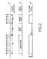
- FIG 2 is a diagram illustrating the sleep mode operation proposed by the IEEE 802.16e communication system.
- the sleep mode has been proposed in order to minimize power consumption of the subscriber stations during an idle interval, during which packet data is not transmitted.
- the subscriber stations and the base station simultaneously perform a mode change into the sleep mode in such a manner that power consumption of the subscriber stations is minimized through the sleep mode during the idle interval in which packet data is not transmitted.
- the base station and the subscriber stations simultaneously change modes into the awake modes to transmit/receive the packet data.
- the sleep mode operation has been proposed for minimizing interference between channel signals. Also, the sleep mode operation must be capable of flexible operation consider traffic characteristics and transmission mode characteristics of the packet data, because the characteristics of the packet data are greatly affected by the traffic.
- reference numeral 31 represents a packet data generation pattern.
- the packet data generation pattern includes a plurality of 'on' intervals and 'off' intervals.
- the 'on' intervals are burst intervals during which the packet data is generated and the 'off' intervals are idle intervals during which no packet data is generated.
- the subscriber stations and the base station perform the mode change between the sleep mode and the awake mode to coincide with the packet data generation pattern so that power consumption of the subscriber stations is minimized and mutual interference between channel signals is eliminated.
- Reference numeral 33 represents a mode change pattern of the base station and the subscriber stations.
- the mode change pattern includes a plurality of awake modes and sleep modes. In the awake modes, the packet data is generated. The base station and the subscriber stations communicate with each other through the packet data in the awake mode. In contrast, the packet data is not generated in the sleep modes. The base station and the subscriber stations do not communicate with each other through packet data in the sleep mode.
- Reference numeral 35 represents a power level pattern of the subscriber station SS POWER LEVEL.
- the SS POWER LEVEL of the awake mode is represented as 'K' and the SS POWER LEVEL of the sleep mode is represented as 'M'.
- the value of 'M' is much less than that of 'K'. Since there is no transmission/reception of the packet data during the sleep mode the power consumption is at a minimum.
- the subscriber stations must obtain approval below the base station for the mode change into the sleep mode.
- the base station is required to perform a buffering operation and a dropping operation for the packet data to be transmitted while approving the mode change of the subscriber stations into the sleep mode.
- the base station is required to notify the subscriber stations if the existence of the packet data to be transmitted during a listening interval of the subscriber stations. At this time, the subscriber stations are required to awake from the sleep mode and check for the existence of the packet data to be transmitted thereto from the base station.
- the listening interval will be described in detail further below.
- the subscriber station awakes during a listening interval. If the subscriber stations detect that packet data is to be transmitted thereto from the base station as a result of inspection during the listening interval, the subscriber stations remains in the awake mode to receive the packet data from the base station. In contrast, if the subscriber stations detect that no packet data is to be transmitted thereto from the base station as a result of the inspection, the subscriber stations may return to the sleep mode after the listening interval or continuously maintain the awake mode.
- a subscriber station requests a sleep interval.
- the sleep interval is assigned by the base station according to a request from the subscriber station.
- the sleep interval represents a time interval required for the subscriber station to perform the mode change into the sleep mode and again to perform the mode change into the awake mode. That is, the sleep interval is defined as a sleep mode operating time of the subscriber station.
- the subscriber station may continuously maintain the sleep mode after the sleep interval.
- the sleep interval is updated by performing an exponentially increasing algorithm with using a predetermined minimum window MIN-WINDOW value and a predetermined maximum window MAX-WINDOW value.
- the minimum window value represents a minimum value of the sleep interval and the maximum window value represents a maximum value of the sleep interval. Also, the minimum value and the maximum value, represented in terms of a number of frames, are assigned by the base station. The minimum window value and the maximum window value will be described in further detail below.
- a listening interval is requested for the subscriber station.
- the listening interval represents a time interval required for the subscriber station to receive downlink messages (e.g., a traffic indicator TRF-IND message) from the base station after awaking from the sleep mode.
- downlink messages e.g., a traffic indicator TRF-IND message
- the TRF-IND message is a traffic message transmitted to the subscriber station (i.e., a message indicating the existence of packet data).
- the TRF-IND message will be described below in further detail.
- the subscriber station determines whether to maintain the awake mode or to perform the mode change into the sleep mode again according to value of the TRF-IND message.
- the subscriber station When the subscriber station performs the mode change into the sleep mode, the subscriber station regards the predetermined minimum window value as a minimum sleep mode period in order to determine the sleep interval. After the sleep interval elapses, the subscriber station awakes from the sleep mode and checks determines if packet data exists to be transmitted from the base station.
- the subscriber station After the subscriber station confirms that there is no packet data to transmit, the subscriber station sets the sleep interval to double that of the previous sleep interval. The subscriber station maintains the sleep mode during the set sleep interval and awakes from the sleep mode often the set sleep interval.
- the subscriber station establishes an initial sleep interval as two frames and maintains the sleep mode during the sleep interval of two frames. After the sleep interval of the two frames elapses, the subscriber station awakes from the sleep mode and then determines whether or not the traffic indicator message is received. As a result of the determination, if the traffic indicator message is not received (that is, the subscriber station confirms that there is no packet data to be transmitted from the base station), the subscriber station establishes the sleep interval as four frames, which is double that of the previous two frames established in the previous initial sleep interval.
- the subscriber station repeatedly performs the sleep mode and the awake mode while increasing the sleep interval from the minimum window value up to the maximum window value within a maximum window time interval.
- An operation increasing the sleep interval whenever the subscriber station enters into the sleep mode is called "sleep interval update algorithm".
- the following are messages defined in the IEEE 802.16e communication system to support the above-described sleep mode operation and awake mode operation.
- a sleep request message is transmitted from the base station to the subscriber station for requesting the subscriber station to change into the sleep mode.
- the sleep request message includes parameters, which are information elements (Ies), required for the subscriber station to operate in the sleep mode.
- the format of the sleep request message is represented in following Table 1.
- the sleep request message is a dedicated message transmitted on the basis of a connection identification CID of the subscriber station.
- each IE of the sleep request message shown in Table 1 will be described.
- the management message type MANAGEMENT MESSAGE TYPE describes a type of a message which is currently being transmitted.
- the minimum window value represents a start value requested for the sleep interval (measured in frames).
- the maximum window MAX-WINDOW represents a stop value requested for the sleep interval (measured in frames).
- the sleep interval can be updated to a value between the minimum window value and the maximum window value.
- the minimum window value is set to 2ms and the maximum window value is set to 5ms.
- the listening interval LISTENING INTERVAL represents a requested listening interval LISTENING INTERVAL (measured in frames).
- the listening interval is also represented in frames.
- the sleep response message is a response message for the sleep request message.
- the sleep response message can be used to represent whether or not the base station approves or denies the mode change into the sleep mode requested by the subscriber station. Also, the sleep response message can be used to represent an unsolicited instruction.
- the sleep response message includes information required for the subscriber station to operate in the sleep mode.
- the format of the sleep response message is represented in following Table 2.
- the sleep response message is also a dedicated message transmitted on the basis of the connection identification of the subscriber station.
- each IE of the sleep response message shown in Table 2 will be described.
- the management message type MANAGEMENT MESSAGE TYPE represents the type of a message which is currently being transmitted.
- the sleep approved SLEEP-APPROVED value is one bit.
- a sleep approved value of '0' represents that the mode change into the sleep mode is denied.
- a sleep approved value of '1' represents that the mode change into the sleep mode is approved. If the sleep approved value is '0', is the sleep response message contains a reservation field having 7 bits. If the sleep approved value is '1', is the sleep response message contains a start time value, the minimum window value, the maximum window value, and the listening interval.
- the start time START-TIME value is the number of frames before the subscriber-station enters into the first sleep interval (the first SLEEP INTERVAL), and the frame receiving the sleep response message is not included in the frames. That is, the subscriber station performs the mode change into the sleep mode after a predetermined number of frames elapse, in which the predetermined number of frames extend from a frame prior to the frame receiving the sleep response message to a frame corresponding to the start time.
- the minimum window MIN-WINDOW value represents a start value for the SLEEP INTERVAL (measured in frames).
- the maximum window MAX-WINDOW represents a stop value for the SLEEP INTERVAL (measured in frames).
- the listening interval LISTENING INTERVAL represents a value for the listening interval (measured in frames).
- the traffic indication message is transmitted to the subscriber station by the base station during the listening interval and indicates the existence of packet data to be transmitted to the subscriber station by the base station.
- the format of the traffic indication message is represented in following Table 3.
- the traffic indication message is transmitted in a broadcasting method, which is different from the transmitting methods for the sleep request message and the sleep response message.
- the traffic indication message indicates whether or not there exists packet data to be transmitted to predetermined subscriber stations by the base station.
- the subscriber station decodes the broadcasted traffic indication message and determines whether to perform the mode change into the awake mode or to maintain the sleep mode. The subscriber station awakens for the above process.
- the subscriber station performs a frame synchronization. If a frame sequence number of packet data transmitted to the subscriber station does not coincide with a frame sequence number expected by the subscriber station, the subscriber station can request that the packet data be retransmitted. In contrast, if the subscriber station does not receive the traffic indication message during the listening interval, the subscriber station returns to the sleep mode. Although the subscriber station receives the traffic indication message, if the traffic indication message does not include a positive indication POSITIVE INDICATION (i.e. includes a negative indication NEGATIVE INDICATION) the subscriber station also returns to the sleep mode.
- POSITIVE INDICATION i.e. includes a negative indication NEGATIVE INDICATION
- the management message type MANAGEMENT MESSAGE TYPE indicates the type of a message which is currently transmitted.
- the positive indication list POSITIVE_INDICATION_LIST includes the number of positive subscribers NUM-POSITIVE and connection identification of each positive subscriber.
- the positive indication list represents the number of the subscriber stations to which packet data will be transmitted and connection identifications of the subscriber stations.
- FIG 3 is a diagram illustrating a mode change procedure of a subscriber station into a sleep mode which has been proposed by the IEEE 802.16e communication system.
- the subscriber station 40 determines that a mode change into the sleep mode is required, the subscriber station 40 transmits the sleep request message to a base station 50 (S31).
- the sleep request message includes the information elements described in Table 1.
- the base station 50 which has received the sleep request message from the subscriber station 40, determines operating conditions of the subscriber station 40 and the base station 50, and determines whether or not to approve the mode change of the subscriber station 40 into the sleep mode. As a result of the determination, the base station 50 transmits the sleep response message to the subscriber station 40 (S33).
- the base station 50 determines whether or not there is packet data to be transmitted to the subscriber station 40, and determines whether or not to approve the mode change of the subscriber station 40 into the sleep mode. As described in Table 2, if the base station 50 approves of the mode change into the sleep mode, the SLEEP-APPROVED value is set as '1'. In contrast, if the base station 50 denies the mode change into the sleep mode, the SLEEP-APPROVED value is set as '0'.
- the other information elements included in the sleep response message are the same as that described in Table 2.
- the subscriber station 40 which has received the sleep response message from the base station 50, detects the SLEEP-APPROVED value, and the subscriber station 40 performs the mode change into the sleep mode when the mode change into the sleep mode is approved (S35).
- the SLEEP-APPROVED value included in the sleep response message represents that the mode change into the sleep mode is denied
- the subscriber station 40 maintains a current mode, that is, the awake mode.
- the subscriber station 40 reads corresponding information elements from the -sleep response message and performs the sleep mode operation, while performing the mode change into the sleep mode.
- FIG 4 is a diagram illustrating a mode change procedure of the subscriber station into a sleep mode under the control of the base station which has been proposed for the IEEE 802.16e based communication system.
- FIG 4 is a diagram illustrating a case where the subscriber station performs the mode change into the sleep mode according to the unsolicited instruction.
- the base station 50 transmits the sleep response message to the subscriber station 40 (S41).
- the sleep response message includes the same information elements as described in Table 2.
- the subscriber station 40 which has received the sleep message from the base station 50, detects the SLEEP-APPROVED value included in the sleep response message and performs the mode change into the sleep mode when the mode change into the sleep mode is approved (S43).
- the SLEEP-APPROVED value is represented as only '1'. Also, the subscriber station 40 reads corresponding information elements from the sleep response message and performs the sleep mode operation, while performing the mode change into the sleep mode.
- FIG 5 is a diagram illustrating a mode change procedure of the subscriber station into a awake mode under the control of the base station which has been proposed for use in an IEEE 802.16e based communication system.
- the base station 50 transmits the traffic indication message to the subscriber station 40 (S51).
- the traffic indication message includes the same information elements as described in Table 3.
- the subscriber station 40 which has received the traffic indication message from the base station 50, checks whether or not the positive indication exits in the traffic indication message. If the positive indication exists, the subscriber station 40 determines is a connection identification is included in the traffic indication message.
- the subscriber station 40 performs the mode change from a current mode, that is, the sleep mode into the awake mode (S53).
- FIG 6 is a diagram illustrating the above-described sleep mode operations which have been proposed for IEEE 80.16e communication system.
- a subscriber station SS 60 transmits to a base station BS 70 a message requesting the sleep mode.
- Parameters for the sleep request include a minimum window value, a maximum window value, and a listening interval which are established by the subscriber-station 60.
- the base station 70 which has received the sleep request message, establishes a sleep response message SLEEP-RESPONSE corresponding to the sleep request message and transmits the sleep response message to the subscriber station 60.
- the sleep response message includes a minimum window value, a maximum window value, and a listening interval, and a sleep mode starting time, which the base station 70 assigns to the subscriber station 60.
- Each value is expressed in frames and seconds (sec).
- the subscriber station 60 After the subscriber station 60, which has received the sleep response message, operates in the sleep mode during the established time starting at the sleep mode starting time, the subscriber station 60 awakes during time assigned as the listening interval. If the subscriber station 60 in the awake mode receives the traffic indication message having the negative indication from the base station 70, the subscriber station 60 reenters the sleep mode for a predetermined time, which is double that of the previous sleep interval, after the listening interval lapses. If the subscriber station 60, which maintains the awake mode during the listening interval after the sleep mode has been finished, receives the traffic indication message having the positive indication, the subscriber station 60 maintains the awake mode regardless of time, and receives data transmitted from the base station 70, which is set for the mode change into the sleep mode.
- the subscriber station in the sleep mode establishes the sleep interval starting from the minimum window value and checks whether or not there exits packet data to be transmitted thereto by using the traffic indication message transmitted from the base station during the listening interval after the sleep interval lapses.
- the subscriber station determines that there does not exists packet data to be transmitted thereto after checking the traffic indication message, the subscriber station increases the sleep interval by an interval double that of the previous sleep interval and maintains the sleep mode during the time corresponding to the increased sleep interval after the listening interval lapses. While the above operation of increasing the sleep interval is being continuously repeated, if there is no packet data to be transmitted to the subscriber station, the sleep interval reaches the maximum window value.
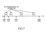
- FIG 7 is a diagram illustrating a conventional sleep mode. It is assumed that the minimum window value is 2ms, the maximum window value is 5ms, and the listening interval is 2ms.
- the subscriber station maintains the sleep mode during the first stage of 2ms. After the first stage lapses, the subscriber station maintains the listening interval while powering on for the next 2ms.
- the subscriber station maintains the second sleep mode after the listening interval of 2ms.
- the last sleep mode of the subscriber station is a 12th sleep interval.
- the sleep interval for the sleep mode is 4.096s, which is a integer interger of 2ms.
- the minimum window value and the maximum window value are assigned to the subscriber station.
- the minimum window value and the maximum value are always maintained as an assigned value. Accordingly, the current state of the art has a problem in that even if it is unnecessary for data transmission to be performed between the subscriber-station and the base station, the subscriber station is required to maintain the awake mode during the assigned time. Also, the current state of the art has a problem in that power save, which is an ultimate object of the sleep mode, is not efficiently achieved, because the subscriber station is required to be maintained in the awake mode during the assigned time even if it is unnecessary for data transmission to be performed between the subscriber station and the base station.
- the present invention is proposed to solve the above-mentioned problems occurring in the prior art.
- An aspect of the present invention is to provide a method for establishing a sleep interval which can re-establish the sleep interval by considering communication traffic conditions for data transmission between a base station and a subscriber station by repeating the sleep mode up to the maximum window value after the sleep interval for the sleep mode reaches a maximum window value from a minimum window value.
- Another aspect of the present invention is to provide a method for establishing a sleep interval, which is capable of efficiently saving power of a system whenever a sleep mode loop is performed.
- a further aspect of the present invention is to provide an apparatus for establishing a sleep interval according to the above-defined methods.
- a method for establishing a sleep interval of a sleep mode in a broadband wireless access communication system comprising the steps of: placing a subscriber station into an awake mode when a preset time of a maximum window value lapses, and determining by the subscriber station if a first message representing that no data is to be transmitted is received from a base station; and placing the subscriber station into the sleep mode when the subscriber station receives the first message, and establishing a minimum window value for a present sleep mode to be greater than a predetermined minimum window value of a previous sleep mode loop within the maximum window value, wherein the previous sleep mode loop repeatedly performs the sleep mode from the preset minimum window value to the maximum window value, and the subscriber station performs a present sleep mode loop until the sleep mode of the maximum window value starting from the established minimum window value is finished.
- the sleep mode loop is carried out so as to set the minimum window value as integer multiple of the initial minimum window value.
- the sleep mode loop is repeatedly carried out such that the sleep mode is performed until the sleep interval reaches the maximum window value.
- the minimum window value is established at multiples of the minimum window value of the previous sleep mode loop. Even if the sleep interval starting from the minimum window value peaches the maximum window value, the sleep mode loop is realized.
- the sleep interval can be established depending on communication traffic conditions for data transmission carried out between the base station and the subscriber station.
- FIG. 8 is a diagram illustrating a structure of a broadband wireless access communication system using an orthogonal frequency division multiplexing method and an orthogonal frequency division multiple access method.
- an IEEE (Institute of Electrical and Electronics Engineers) 802.16e communication system is achieved by supplementing an IEEE 802.16a communication system with means to compensate for the mobility of a subscriber station SS
- the IEEE 802.16e communication system When the IEEE 802.16e communication system is compensates for the mobility of the subscriber station, a multi-cell structure and handoff of the subscriber station between multi-cells can be considered. According to the present invention, a structure of the IEEE 802.16e communication system is proposed as shown in FIG. 8.
- the IEEE 802.16e communication system is a broadband wireless access (BWA) communication system using an orthogonal frequency division multiplexing (hereinafter, referred to as 'OFDM') method and an orthogonal frequency division multiple access (hereinafter, referred to as 'OFDMA') method.
- BWA broadband wireless access
- 'OFDM' orthogonal frequency division multiplexing
- 'OFDMA' orthogonal frequency division multiple access
- the IEEE 802.16e communication system has a multi-cell structure and includes a base station BS 110 controlling a first cell 100, a base station 140 controlling a second cell 150, and a plurality of subscriber stations 111, 113, 130, 151, and 153.
- the base stations 110 and 140 communicate with the subscriber stations 111, 113, 130, 151, and 153 through the OFDM/OFDMA methods.
- the subscriber station 130 of the subscriber stations 111, 113, 130, 151, and 153 is located at a boundary area between two cells, i.e., at an handoff area.
- the IEEE 802.16e communication system provides means for compensating for the mobility of the subscriber station 130 only when a handoff function for the subscriber station 130 has been provided.
- the IEEE 802.16e communication system is achieved by supplementing the IEEE 802.16a communication system with means for compensating the mobility of the subscriber station
- power consumption of the subscriber station is a major factor to be considered while designing the IEEE 802.16e communication system.
- a sleep mode operation and an awake mode operation corresponding to the sleep mode operation between the subscriber-station and the base station have been proposed.
- the sleep mode operation and the awake mode operation proposed for the current IEEE 802.16e communication system exhibits problems in that there are no methods for controlling an operation after the sleep interval reaches a maximum window value when establishing the sleep interval.
- the methods proposed by the present invention of establishing the sleep interval include a first method of continuously maintaining the sleep interval value as the maximum window value, and a second method of continuously repeating operations, in which the sleep interval value is set as the minimum window value and the sleep interval value is increased up to the maximum window value. Also, a third method of transmitting a sleep request message for establishing a new sleep interval when the sleep interval value reaches the maximum window value is contemplated.
- the sleep mode is performed by using predetermined window values without considering the status of communication trade between the base station and each subscriber station.
- the subscriber station requests from the base station the sleep request message for establishing a new sleep interval whenever the sleep interval value reaches the maximum window value, and receives a response corresponding to the sleep request message in order to establish the sleep mode.
- FIG. 9 is a diagram of a method for establishing a sleep interval of a subscriber station when performing a sleep mode loop according to a preferred embodiment of the present invention.
- a sleep mode loop refers to a process where the sleep mode is repeatedly performed from a new established minimum window value to the maximum window value after the sleep mode has been performed during a previously established interval until the sleep interval starts from the minimum window value and reaches the maximum window value.
- the base station When the base station has no data to transmit, the base station transmits to the subscriber station a traffic indication message having negative information.
- the subscriber station which has received the traffic indication message having negative information, continuously stays in the sleep mode. Since data to be transmitted by the base station is not transmitted in real time, the data is randomly generated.
- the minimum window value is doubled after establishing the minimum window value greater than the initial minimum window value.
- the subscriber station 220 maintains the sleep mode during the sleep interval 311corresponding to the minimum window value (S210).
- the subscriber station 220 which has performed the mode change into the sleep mode (S210), performs the mode change into the awake mode (S211) after the minimum window value 311 lapses, thereby receiving the traffic indication message from the base station 240 (S212).
- the awake mode is a mode for allowing the subscriber station 220 to receive the traffic indication message from the base station 240 during the listening interval.
- the subscriber station 220 performs the mode change into a second sleep mode in a first sleep mode loop (S213). At this time, the subscriber station 220 sets the sleep interval as twice that of the first sleep interval, i.e., the minimum window value (2 * MinWindow) 312. The subscriber station 220,now in the second sleep mode, performs the mode change into the awake mode after the preset time, which is double that of a time required for the first sleep interval, lapses (S214). The subscriber station 220 receives the traffic indication message from the base station 240 (S215).
- the subscriber station 220 When the negative traffic indication message is received as the traffic indication message, the subscriber station 220 establishes the sleep interval in the same manner as described above until the sleep interval reaches the maximum window value. The subscriber station 220 repeats the sleep mode in the sleep interval and the awake mode in the listening interval depending the above- established sleep interval.
- the subscriber station 220 If the sleep interval reaches the maximum window value, the subscriber station 220 maintains the sleep mode during the sleep interval 315 corresponding to the maximum window value. The subscriber station 220 then performs the mode change into the awake mode after the sleep interval 315 of the maximum window value lapses (S217). The subscriber station 220 receives the traffic indication message from the base station 240 (S218). If a received traffic indication message is the negative traffic indication message, the subscriber station 220 performs a second sleep mode loop in order to operate in the sleep mode.
- the minimum window value is 4ms in the second sleep mode loop.
- the subscriber station 220 then maintains the sleep mode during the sleep interval 411 corresponding to a established minimum window value. If the sleep interval 411 lapses, the subscriber station 220 performs the mode change into the awake mode (S220), thereby receiving the traffic indication message from the base station 240 (S221).
- the subscriber station 220 performs the mode change into the sleep mode (S222). At this time, the subscriber station 220 establishes the sleep interval used for remaining in the sleep mode as double that of the previous sleep interval. After the subscriber station 220 maintains the sleep mode during double time 412 as compared with the previous sleep mode, the subscriber station 220 performs the mode change into the awake mode (S223).
- the subscriber station 220 If the subscriber station 220 does not receive a positive traffic indication message from the base station, the subscriber station 220 repeatedly performs the sleep mode loop in the same manner as described above. At this time, if the minimum window value of the sleep interval exceeds the maximum window value, the subscriber station 220 establishes the sleep interval established in the previous sleep mode as the sleep interval for a present sleep mode.
- the sleep mode loop is carried out so as to set the minimum window value as integer multiple of the initial minimum window value.
- the sleep mode loop is repeatedly carried out such that the sleep mode is performed until the sleep interval reaches the maximum window value.
- the minimum window value is established as a multiple of the minimum window value of the previous sleep mode loop. Even if the sleep interval starting from the minimum window value reaches the maximum window value, the sleep mode loop is realized.
- the sleep interval can be established depending on communication traffic conditions for data transmission carried out between the base station and the subscriber station.
- the sleep interval can also be established by considerating communication traffic conditions between the base station and the subscriber station in both sleep mode and awake mode of the broadband wireless access communication system using the OFDM/OFDMA method, i.e., the IEEE 802.16e communication system so that it is possible to reduce unnecessary awaking times.
- the power save of the IEEE 802.16e communication system which is an object of the sleep mode, can be efficiently achieved.
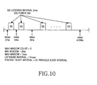
- FIG. 10 is a diagram of parameters in relation to the sleep mode when performing an initial sleep mode loop according to the method of FIG. 9.
- a present sleep interval is set to 2 times the previous sleep interval.
- the subscriber station After the subscriber station maintains the sleep mode for 2ms which is the initial window value, i.e. the minimum window value, the subscriber station is powered on for 2ms and maintains the awake mode during the listening interval. After the subscriber station maintains the awake mode for 2ms, the subscriber station performs the mode change into the sleep mode and maintains the sleep mode for 4ms.
- a last sleep interval window value is 4.096sec, which is less than the maximum window value.
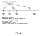
- FIG. 11 is a diagram of parameters in relation to the sleep mode when performing the second sleep mode loop according to the method of FIG. 9.
- the subscriber station After the subscriber station maintains the sleep mode in the second sleep loop for 4ms, which is the minimum window value, the subscriber station is powered on for 2ms and maintains the awake mode during the listening interval. After the subscriber station maintains the awake mode for 2ms, the subscriber station performs the mode change into the sleep mode and maintains the sleep mode for 8ms.
- the last sleep interval window value is 4.096sec, which is less than the maximum window value.
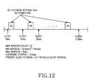
- FIG. 12 is a diagram of parameters in relation to the sleep mode when performing a third sleep mode loop according to the method of FIG. 9.
- the subscriber station After the subscriber station maintains the sleep mode in the second sleep loop for 8ms, which is the minimum window value, the subscriber station is powered on for 2ms and maintains the awake mode during the listening interval. After the subscriber station maintains the awake mode for 2ms, the subscriber station performs the mode change into the sleep mode and maintains the sleep mode for 16ms.
- the last sleep interval window value is 4.096sec, which is less than the maximum window value.
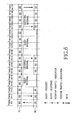
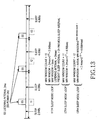
- FIG. 13 is a diagram of parameters in relation to the sleep mode when performing 11 th , 12 th , and 13 th sleep mode loops according to the method of FIG. 9.
- the subscriber station After the subscriber station maintains the sleep mode in the 11 th sleep loop for 2.048sec, which is the minimum window value, the subscriber station is powered on for 2ms and maintains the awake mode during the listening interval. After the subscriber station maintains the awake mode for 2ms, the subscriber station performs the mode change into the sleep mode and maintains the sleep mode for 4.096sec.
- the last sleep interval window value is 4.096sec, which is less than the maximum window value.
- the subscriber station After the subscriber station maintains the sleep mode in the 12 th sleep loop for 4.096sec, which is the minimum window value, the subscriber station is powered on for 2ms and maintains the awake mode during the listening interval. After the subscriber station maintains the awake mode for 2ms, the subscriber station performs the mode change into the sleep mode and the sleep mode for 4.096sec.
- the current sleep interval is set to 2 times the previous sleep interval.
- MinWindow initial MinWindow*2 MaxWindowCount-1 .
- the subscriber station After the subscriber station maintains the sleep mode in the 13 th sleep loop for 4.096sec, which is the minimum window value, the subscriber station is powered on for 2ms and maintains the awake mode during the listening interval. After the subscriber station maintains the awake mode for 2ms, the subscriber station performs the mode change into the sleep mode and maintains the sleep mode for 4.096sec.
- FIG. 14 is a flow chart showing an operation of the subscriber station based on FIG 9.
- the subscriber station receives information representing the initial minimum window value, the maximum window value, and the listening interval and establishes the maximum window count as '0' (S510).
- the subscriber station performs the sleep mode operation depending on the sleep interval established until the sleep interval reaches the maximum window value during the sleep mode loop (S520).
- the subscriber station adds '1' to the maximum window count (S530). Also, as shown in Equation 1, the minimum window value is calculated by multiplying the initial minimum window value by 2 raised to the maximum window count of a current sleep mode loop power (S540).
- the subscriber station compares the above-calculated minimum window value with the maximum window value (S550). If the subscriber station determines that the minimum window value calculated by step 540 is less than the maximum window, the subscriber station repeatedly performs steps 520 to 550 performing the sleep mode according to the established sleep interval.
- the subscriber terminal determines that the minimum window value calculated by step 540 is greater than the maximum window value, the subscriber terminal -calculates the sleep interval by Equation 2 (S560). After the subscriber station maintains the sleep mode during the calculated sleep interval, the subscriber station performs the sate transition into the awake mode and maintains the awake mode for 2ms, and then the subscriber station repeatedly performs the sleep mode again during the sleep interval calculated in step 560 (S570).
- the subscriber station determines whether or not the positive traffic indication message is received during the listening interval of the awake mode in step 570 (S580). If the positive traffic indication message is not received, the subscriber station repeatedly performs the sleep mode by using the sleep interval calculated in step 560.
- the subscriber station performs the mode change into the awake mode by turning on its power, to thereby receive data from the base station (S590).
- the subscriber station After the subscriber station receives the positive traffic indication message from the base station and communicates data with the base station, the subscriber station initializes the minimum window value and the maximum window count. In other words, the subscriber station establishes the minimum window value as the initial window value (2ms), resets the maximum window count as '0', and then performs step 510 to step 590.
- the sleep mode loop is carried out so as to set the minimum window value as an integer multiple of the initial minimum window value.
- the sleep mode loop is repeatedly carried out such that the sleep mode is performed until the sleep interval reaches the maximum window value.
- the minimum window value is established at multiples of the minimum window value of the previous sleep mode loop. Even if the sleep interval starting from the minimum window value reaches the maximum window value, the sleep mode loop is realized.
- the sleep interval can be established depending on communication traffic conditions for data transmission carried out between the base station and the subscriber station.
- the sleep interval can be established by considerating the communication traffic conditions between the base station and the subscriber station in both sleep mode and awake mode of the broadband wireless access communication system using the OFDM/OFDMA method, i.e., the IEEE 802.16e communication system, so that it is possible to reduce unnecessary awaking times.
- the power save of the IEEE 802.16e communication system which is an object of the sleep mode, can be efficiently achieved.
Landscapes
- Engineering & Computer Science (AREA)
- Computer Networks & Wireless Communication (AREA)
- Signal Processing (AREA)
- Mobile Radio Communication Systems (AREA)
Applications Claiming Priority (2)
| Application Number | Priority Date | Filing Date | Title |
|---|---|---|---|
| KR2003067085 | 2003-09-26 | ||
| KR1020030067085A KR100594009B1 (ko) | 2003-09-26 | 2003-09-26 | 광대역 무선 접속 통신 시스템에서 슬립 구간 설정 방법 |
Publications (3)
| Publication Number | Publication Date |
|---|---|
| EP1519599A2 true EP1519599A2 (de) | 2005-03-30 |
| EP1519599A3 EP1519599A3 (de) | 2005-09-28 |
| EP1519599B1 EP1519599B1 (de) | 2008-10-15 |
Family
ID=34192275
Family Applications (1)
| Application Number | Title | Priority Date | Filing Date |
|---|---|---|---|
| EP04018838A Expired - Lifetime EP1519599B1 (de) | 2003-09-26 | 2004-08-09 | Verfahren zur Steuerung des Schlafzeitintervalls in einem drahtlosen Breitband-Zugangskommunikationssystem |
Country Status (5)
| Country | Link |
|---|---|
| US (1) | US7289804B2 (de) |
| EP (1) | EP1519599B1 (de) |
| KR (1) | KR100594009B1 (de) |
| CN (1) | CN1602013A (de) |
| DE (1) | DE602004017098D1 (de) |
Cited By (5)
| Publication number | Priority date | Publication date | Assignee | Title |
|---|---|---|---|---|
| EP1786146A1 (de) * | 2005-09-26 | 2007-05-16 | Samsung Electronics Co., Ltd. | Verfahren und Vorrichtung zum Energiesparen bei der Steuerung der Lauschperioden in drahtlosen Telekomunikationsendgeräten mit einer Vielfach von Energiesparbetriebe |
| WO2007076139A3 (en) * | 2005-12-27 | 2007-09-13 | Olympus Comm Technology Of Ame | Dynamic power save modes |
| WO2008005689A3 (en) * | 2006-07-05 | 2008-05-29 | Motorola Inc | Sleep mode optimization for increasing battery life in broadband wireless communication devices |
| US7751357B2 (en) | 2006-02-06 | 2010-07-06 | Olympus Corporation | Power management |
| US7769362B2 (en) | 2006-06-23 | 2010-08-03 | Olympus Corporation | System and method for power management |
Families Citing this family (49)
| Publication number | Priority date | Publication date | Assignee | Title |
|---|---|---|---|---|
| US6950645B1 (en) * | 2000-09-28 | 2005-09-27 | Palmsource, Inc. | Power-conserving intuitive device discovery technique in a bluetooth environment |
| US6721569B1 (en) * | 2000-09-29 | 2004-04-13 | Nortel Networks Limited | Dynamic sub-carrier assignment in OFDM systems |
| WO2005022772A1 (en) * | 2003-08-29 | 2005-03-10 | Samsung Electronics Co., Ltd. | Apparatus and method for controlling operational states of medium access control layer in a broadband wireless access communication system |
| CA2760916C (en) * | 2004-03-04 | 2013-12-10 | Samsung Electronics Co., Ltd. | A system and method for performing location update |
| KR100885158B1 (ko) * | 2004-08-09 | 2009-02-23 | 엘지전자 주식회사 | 광대역 무선접속 시스템에서 수면모드 단말의 주기적인레인징방법 |
| US7408887B2 (en) * | 2004-10-27 | 2008-08-05 | Intel Corporation | Methods and apparatus for operating a wireless electronic device based on usage pattern |
| WO2006049460A1 (en) * | 2004-11-04 | 2006-05-11 | Samsung Electronics Co., Ltd. | Apparatus and method for signal transmission and reception using downlink channel information in a sleep mode in a bwa communication system |
| US8379553B2 (en) * | 2004-11-22 | 2013-02-19 | Qualcomm Incorporated | Method and apparatus for mitigating the impact of receiving unsolicited IP packets at a wireless device |
| US7593745B2 (en) * | 2005-01-05 | 2009-09-22 | Faraday Technology Corp. | Method for operating wireless local area network cards in a power-saving mode |
| KR101084129B1 (ko) * | 2005-03-24 | 2011-11-17 | 엘지전자 주식회사 | 광대역 무선접속 시스템에서의 슬립모드 지원 방법 |
| KR100913087B1 (ko) | 2005-06-09 | 2009-08-21 | 엘지전자 주식회사 | 전력소모 방지 모드에서 핸드오버 제어 방법 |
| KR20070024302A (ko) * | 2005-08-26 | 2007-03-02 | 한국전자통신연구원 | 셀룰러 시스템의 수면 모드 제어 장치 및 제어 방법 |
| US7567820B2 (en) * | 2006-02-09 | 2009-07-28 | Altair Semiconductor Ltd. | Scanning for network connnections with variable scan rate |
| US7545787B2 (en) * | 2006-02-09 | 2009-06-09 | Altair Semiconductor Ltd. | Simultaneous operation of wireless LAN and long-range wireless connections |
| US7542728B2 (en) * | 2006-02-09 | 2009-06-02 | Altair Semiconductor Ltd. | Dual-function wireless data terminal |
| US9258833B2 (en) | 2006-02-09 | 2016-02-09 | Altair Semiconductor Ltd. | LTE/Wi-Fi coexistence |
| US8160001B2 (en) * | 2006-05-25 | 2012-04-17 | Altair Semiconductor Ltd. | Multi-function wireless terminal |
| KR100961706B1 (ko) * | 2006-02-28 | 2010-06-10 | 삼성전자주식회사 | 무선 통신 시스템의 슬립 모드 동작 제어 시스템 및 방법 |
| US7916687B2 (en) * | 2006-03-03 | 2011-03-29 | Qualcomm Incorporated | Standby time improvements |
| US8880104B2 (en) * | 2006-03-03 | 2014-11-04 | Qualcomm Incorporated | Standby time improvements for stations in a wireless network |
| US8433374B2 (en) * | 2006-04-27 | 2013-04-30 | Qualcomm Incorporated | Method and system for selecting a sleep interval to improve battery life |
| US7751858B2 (en) * | 2006-05-05 | 2010-07-06 | Intel Corporation | Sleep-mode statistics apparatus, systems, and methods |
| US9332496B2 (en) * | 2006-11-28 | 2016-05-03 | Marvell World Trade Ltd. | Enhanced IEEE power save in ad hoc wireless mode |
| KR101402986B1 (ko) | 2006-12-01 | 2014-06-03 | 삼성전자주식회사 | 광대역 무선 접속 시스템에서의 수면 모드 관리 장치 및 그방법 |
| US8619652B2 (en) * | 2006-12-04 | 2013-12-31 | Samsung Electronics Co., Ltd. | System and method for adaptive sleep of wirelessly networked devices |
| US8826348B2 (en) * | 2006-12-04 | 2014-09-02 | Samsung Electronics Co., Ltd. | System and method for wireless communication of uncompressed video having a relay device for power saving |
| KR100925712B1 (ko) * | 2007-01-22 | 2009-11-10 | 삼성전자주식회사 | 광대역 무선통신 시스템에서 슬립 모드 진입을 제어하기위한 장치 및 방법 |
| CN101237640B (zh) * | 2007-01-30 | 2014-06-04 | 世意法(北京)半导体研发有限责任公司 | 在宽带无线接入通信系统中用于实时服务的睡眠模式控制 |
| US7787406B2 (en) * | 2007-04-18 | 2010-08-31 | Intel Corporation | Methods and arrangements for adaptively changing snoozing intervals of wireless devices |
| KR100897424B1 (ko) * | 2007-05-14 | 2009-05-14 | 한국전자통신연구원 | 수면 모드를 제공하는 방법과 이를 위한 이동 단말기 |
| KR101340177B1 (ko) | 2007-10-19 | 2014-01-15 | 삼성전자주식회사 | 통신 시스템에서 슬립모드 동작 제어 방법 및 장치 |
| US8121144B2 (en) * | 2007-11-20 | 2012-02-21 | Altair Semiconductor Ltd. | Multi-function wireless terminal |
| US8095106B2 (en) * | 2008-02-14 | 2012-01-10 | Industrial Technology Research Institute | System and method for power savings in a wireless communication network |
| KR101094431B1 (ko) * | 2008-02-28 | 2011-12-15 | 한국전자통신연구원 | 이동 통신 시스템에서 전력 절약 동작 관리 방법 |
| US9237523B2 (en) | 2008-07-07 | 2016-01-12 | Mediatek Inc. | Method of establishing sleep mode operation for broadband wireless communications systems |
| US20100067416A1 (en) * | 2008-09-15 | 2010-03-18 | Qualcomm Incorporated | Re-programming media flow phone using speed channel switch time through sleep time line |
| US8638701B2 (en) * | 2008-09-26 | 2014-01-28 | Nxp, B.V. | Methods and apparatus for power saving in personal area networks |
| US8699509B2 (en) * | 2008-10-29 | 2014-04-15 | Qualcomm Incorporated | Methods and systems for diversity idle mode in a mobile station |
| KR101718496B1 (ko) * | 2008-10-30 | 2017-03-21 | 한국전자통신연구원 | 다중 반송파 관리 장치 및 방법과 단말의 수면 모드 동작 방법 |
| EP2205029A1 (de) * | 2009-01-06 | 2010-07-07 | Thomson Licensing | Verfahren zum Planen der Wach-/Schlafzyklen von einer zentralen Vorrichtung in einem Funknetzwerk |
| KR101564107B1 (ko) * | 2009-03-11 | 2015-10-29 | 삼성전자주식회사 | 통신 시스템에서 슬립모드 동작 제어 방법 및 장치 |
| US8194576B2 (en) * | 2009-03-27 | 2012-06-05 | Research In Motion Limited | Wireless access point methods and apparatus using dynamically-activated service intervals |
| US9612641B2 (en) * | 2010-11-17 | 2017-04-04 | International Business Machines Corporation | Adjusting the connection idle timeout in connection pools |
| US9237572B2 (en) | 2011-06-12 | 2016-01-12 | Altair Semiconductor Ltd. | Mitigation of interference between communication terminals in TD-LTE |
| US9354696B2 (en) * | 2011-09-30 | 2016-05-31 | Intel Corporation | Credit based power management |
| US9247497B2 (en) * | 2012-05-08 | 2016-01-26 | Apple Inc. | Communicating latency-sensitive data over a wireless data link |
| CN104427591A (zh) * | 2013-08-22 | 2015-03-18 | 北京信威通信技术股份有限公司 | 一种通过寻呼检测降低终端功耗的方法和专用装置 |
| KR102059409B1 (ko) * | 2013-10-10 | 2019-12-26 | 한국전자통신연구원 | Ip 기반의 슬립 모드 제어 방법 |
| CN107734620B (zh) * | 2017-11-29 | 2021-03-12 | 新华三技术有限公司 | 一种终端唤醒方法、装置及无线接入设备 |
Family Cites Families (8)
| Publication number | Priority date | Publication date | Assignee | Title |
|---|---|---|---|---|
| GB9304638D0 (en) * | 1993-03-06 | 1993-04-21 | Ncr Int Inc | Wireless data communication system having power saving function |
| US6085090A (en) * | 1997-10-20 | 2000-07-04 | Motorola, Inc. | Autonomous interrogatable information and position device |
| US6678258B1 (en) | 1998-11-30 | 2004-01-13 | Motorola, Inc. | Method and apparatus for paging a communication unit in a packet data communication system |
| US6285662B1 (en) | 1999-05-14 | 2001-09-04 | Nokia Mobile Phones Limited | Apparatus, and associated method for selecting a size of a contention window for a packet of data system |
| US6735454B1 (en) * | 1999-11-04 | 2004-05-11 | Qualcomm, Incorporated | Method and apparatus for activating a high frequency clock following a sleep mode within a mobile station operating in a slotted paging mode |
| US6829493B1 (en) * | 2000-04-24 | 2004-12-07 | Denso Corporation | Adaptive adjustment of sleep duration to increase standby time in wireless mobile stations |
| US6639907B2 (en) * | 2000-09-26 | 2003-10-28 | Qualcomm, Incorporated | Method and apparatus for processing paging indicator bits transmitted on a quick paging channel |
| GB2375015A (en) | 2001-04-27 | 2002-10-30 | Ericsson Telefon Ab L M | Communications networks |
-
2003
- 2003-09-26 KR KR1020030067085A patent/KR100594009B1/ko not_active Expired - Fee Related
-
2004
- 2004-06-25 US US10/876,887 patent/US7289804B2/en not_active Expired - Fee Related
- 2004-08-09 DE DE602004017098T patent/DE602004017098D1/de not_active Expired - Lifetime
- 2004-08-09 EP EP04018838A patent/EP1519599B1/de not_active Expired - Lifetime
- 2004-08-25 CN CNA2004100682469A patent/CN1602013A/zh active Pending
Cited By (8)
| Publication number | Priority date | Publication date | Assignee | Title |
|---|---|---|---|---|
| EP1786146A1 (de) * | 2005-09-26 | 2007-05-16 | Samsung Electronics Co., Ltd. | Verfahren und Vorrichtung zum Energiesparen bei der Steuerung der Lauschperioden in drahtlosen Telekomunikationsendgeräten mit einer Vielfach von Energiesparbetriebe |
| US7899433B2 (en) | 2005-09-26 | 2011-03-01 | Samsung Electronics Co., Ltd. | Method and apparatus for saving power by controlling listening periods in wireless telecommunication device having a plurality for power-saving modes |
| WO2007076139A3 (en) * | 2005-12-27 | 2007-09-13 | Olympus Comm Technology Of Ame | Dynamic power save modes |
| US7751357B2 (en) | 2006-02-06 | 2010-07-06 | Olympus Corporation | Power management |
| US7920504B2 (en) | 2006-02-06 | 2011-04-05 | Olympus Corporation | Power save system and method |
| US8135427B2 (en) | 2006-02-06 | 2012-03-13 | Olympus Corporation | Power save system and method |
| US7769362B2 (en) | 2006-06-23 | 2010-08-03 | Olympus Corporation | System and method for power management |
| WO2008005689A3 (en) * | 2006-07-05 | 2008-05-29 | Motorola Inc | Sleep mode optimization for increasing battery life in broadband wireless communication devices |
Also Published As
| Publication number | Publication date |
|---|---|
| EP1519599A3 (de) | 2005-09-28 |
| KR100594009B1 (ko) | 2006-06-30 |
| EP1519599B1 (de) | 2008-10-15 |
| US20050070340A1 (en) | 2005-03-31 |
| DE602004017098D1 (de) | 2008-11-27 |
| KR20050030510A (ko) | 2005-03-30 |
| CN1602013A (zh) | 2005-03-30 |
| US7289804B2 (en) | 2007-10-30 |
Similar Documents
| Publication | Publication Date | Title |
|---|---|---|
| EP1519599B1 (de) | Verfahren zur Steuerung des Schlafzeitintervalls in einem drahtlosen Breitband-Zugangskommunikationssystem | |
| EP1473880A2 (de) | Verfahren zur Einstellung des Schlafzeitintervalls für drahtlose Breitbandzugriffskommunikationssysteme | |
| US7526288B2 (en) | System and method for controlling operation states of a medium access control layer in a broadband wireless access communication system | |
| KR100643784B1 (ko) | 광대역 무선 접속 통신 시스템의 슬립 모드에서 주기적레인징 시스템 및 방법 | |
| EP1473881B1 (de) | Steuerung des Schlafmodus und Aktivmodus in einem drahtlosen Kommunikationssystem | |
| US20050197171A1 (en) | System and method for periodic ranging in sleep mode in broadband wireless access communication system | |
| CA2556297C (en) | System and method for controlling an operational mode of a mac layer in a broadband wireless access communication system | |
| KR101002907B1 (ko) | 통신 시스템에서 데이터 송수신 시스템 및 방법 | |
| KR100762606B1 (ko) | 광대역 무선 접속 통신 시스템에서 다운링크 채널 정보 변경에 따른 신호 송수신 시스템 및 방법 | |
| CN1930793B (zh) | 用于在宽带无线接入通信系统中由移动用户台执行位置更新的方法 |
Legal Events
| Date | Code | Title | Description |
|---|---|---|---|
| PUAI | Public reference made under article 153(3) epc to a published international application that has entered the european phase |
Free format text: ORIGINAL CODE: 0009012 |
|
| 17P | Request for examination filed |
Effective date: 20040809 |
|
| AK | Designated contracting states |
Kind code of ref document: A2 Designated state(s): AT BE BG CH CY CZ DE DK EE ES FI FR GB GR HU IE IT LI LU MC NL PL PT RO SE SI SK TR |
|
| AX | Request for extension of the european patent |
Extension state: AL HR LT LV MK |
|
| PUAL | Search report despatched |
Free format text: ORIGINAL CODE: 0009013 |
|
| AK | Designated contracting states |
Kind code of ref document: A3 Designated state(s): AT BE BG CH CY CZ DE DK EE ES FI FR GB GR HU IE IT LI LU MC NL PL PT RO SE SI SK TR |
|
| AX | Request for extension of the european patent |
Extension state: AL HR LT LV MK |
|
| AKX | Designation fees paid |
Designated state(s): DE FR GB |
|
| GRAP | Despatch of communication of intention to grant a patent |
Free format text: ORIGINAL CODE: EPIDOSNIGR1 |
|
| GRAS | Grant fee paid |
Free format text: ORIGINAL CODE: EPIDOSNIGR3 |
|
| GRAA | (expected) grant |
Free format text: ORIGINAL CODE: 0009210 |
|
| AK | Designated contracting states |
Kind code of ref document: B1 Designated state(s): DE FR GB |
|
| REG | Reference to a national code |
Ref country code: GB Ref legal event code: FG4D |
|
| REF | Corresponds to: |
Ref document number: 602004017098 Country of ref document: DE Date of ref document: 20081127 Kind code of ref document: P |
|
| PLBE | No opposition filed within time limit |
Free format text: ORIGINAL CODE: 0009261 |
|
| STAA | Information on the status of an ep patent application or granted ep patent |
Free format text: STATUS: NO OPPOSITION FILED WITHIN TIME LIMIT |
|
| 26N | No opposition filed |
Effective date: 20090716 |
|
| REG | Reference to a national code |
Ref country code: FR Ref legal event code: ST Effective date: 20100430 |
|
| PG25 | Lapsed in a contracting state [announced via postgrant information from national office to epo] |
Ref country code: FR Free format text: LAPSE BECAUSE OF NON-PAYMENT OF DUE FEES Effective date: 20090831 |
|
| PGFP | Annual fee paid to national office [announced via postgrant information from national office to epo] |
Ref country code: DE Payment date: 20170720 Year of fee payment: 14 Ref country code: GB Payment date: 20170720 Year of fee payment: 14 |
|
| REG | Reference to a national code |
Ref country code: DE Ref legal event code: R119 Ref document number: 602004017098 Country of ref document: DE |
|
| GBPC | Gb: european patent ceased through non-payment of renewal fee |
Effective date: 20180809 |
|
| PG25 | Lapsed in a contracting state [announced via postgrant information from national office to epo] |
Ref country code: DE Free format text: LAPSE BECAUSE OF NON-PAYMENT OF DUE FEES Effective date: 20190301 |
|
| PG25 | Lapsed in a contracting state [announced via postgrant information from national office to epo] |
Ref country code: GB Free format text: LAPSE BECAUSE OF NON-PAYMENT OF DUE FEES Effective date: 20180809 |