EP1519464A2 - Elektrisches Versorgungs- und Verteilungssystem mit Belüftungseinrichtung - Google Patents
Elektrisches Versorgungs- und Verteilungssystem mit Belüftungseinrichtung Download PDFInfo
- Publication number
- EP1519464A2 EP1519464A2 EP04077649A EP04077649A EP1519464A2 EP 1519464 A2 EP1519464 A2 EP 1519464A2 EP 04077649 A EP04077649 A EP 04077649A EP 04077649 A EP04077649 A EP 04077649A EP 1519464 A2 EP1519464 A2 EP 1519464A2
- Authority
- EP
- European Patent Office
- Prior art keywords
- electrical supply
- distribution system
- box section
- fire
- ventilation means
- Prior art date
- Legal status (The legal status is an assumption and is not a legal conclusion. Google has not performed a legal analysis and makes no representation as to the accuracy of the status listed.)
- Withdrawn
Links
- 238000009423 ventilation Methods 0.000 title claims abstract description 25
- 239000003063 flame retardant Substances 0.000 claims abstract description 14
- 239000000463 material Substances 0.000 claims abstract description 11
- 239000007789 gas Substances 0.000 claims description 19
- 238000001514 detection method Methods 0.000 claims description 18
- 239000012080 ambient air Substances 0.000 claims description 6
- 230000001143 conditioned effect Effects 0.000 claims description 6
- 230000011664 signaling Effects 0.000 claims description 4
- 238000012544 monitoring process Methods 0.000 claims description 2
- 238000001816 cooling Methods 0.000 description 8
- 238000010438 heat treatment Methods 0.000 description 6
- 239000003570 air Substances 0.000 description 3
- 238000004891 communication Methods 0.000 description 3
- 230000000694 effects Effects 0.000 description 3
- 230000005611 electricity Effects 0.000 description 2
- 239000001301 oxygen Substances 0.000 description 2
- 229910052760 oxygen Inorganic materials 0.000 description 2
- 230000000717 retained effect Effects 0.000 description 2
- RYGMFSIKBFXOCR-UHFFFAOYSA-N Copper Chemical compound [Cu] RYGMFSIKBFXOCR-UHFFFAOYSA-N 0.000 description 1
- 241000219130 Cucurbita pepo subsp. pepo Species 0.000 description 1
- 235000003954 Cucurbita pepo var melopepo Nutrition 0.000 description 1
- 241000238631 Hexapoda Species 0.000 description 1
- 230000002411 adverse Effects 0.000 description 1
- 239000004411 aluminium Substances 0.000 description 1
- 229910052782 aluminium Inorganic materials 0.000 description 1
- XAGFODPZIPBFFR-UHFFFAOYSA-N aluminium Chemical compound [Al] XAGFODPZIPBFFR-UHFFFAOYSA-N 0.000 description 1
- QVGXLLKOCUKJST-UHFFFAOYSA-N atomic oxygen Chemical compound [O] QVGXLLKOCUKJST-UHFFFAOYSA-N 0.000 description 1
- 230000005540 biological transmission Effects 0.000 description 1
- 229910052802 copper Inorganic materials 0.000 description 1
- 239000010949 copper Substances 0.000 description 1
- 238000007599 discharging Methods 0.000 description 1
- 239000012777 electrically insulating material Substances 0.000 description 1
- 239000003365 glass fiber Substances 0.000 description 1
- 238000009434 installation Methods 0.000 description 1
- 239000012774 insulation material Substances 0.000 description 1
- 230000014759 maintenance of location Effects 0.000 description 1
- 238000005259 measurement Methods 0.000 description 1
- 229910052751 metal Inorganic materials 0.000 description 1
- 239000002184 metal Substances 0.000 description 1
- 238000000034 method Methods 0.000 description 1
- 230000036961 partial effect Effects 0.000 description 1
- 238000005192 partition Methods 0.000 description 1
- 230000000149 penetrating effect Effects 0.000 description 1
- 238000004321 preservation Methods 0.000 description 1
- 230000002265 prevention Effects 0.000 description 1
- 230000001681 protective effect Effects 0.000 description 1
- 230000002441 reversible effect Effects 0.000 description 1
- 239000000779 smoke Substances 0.000 description 1
- 239000007921 spray Substances 0.000 description 1
- 230000007704 transition Effects 0.000 description 1
Images


Classifications
-
- H—ELECTRICITY
- H01—ELECTRIC ELEMENTS
- H01R—ELECTRICALLY-CONDUCTIVE CONNECTIONS; STRUCTURAL ASSOCIATIONS OF A PLURALITY OF MUTUALLY-INSULATED ELECTRICAL CONNECTING ELEMENTS; COUPLING DEVICES; CURRENT COLLECTORS
- H01R25/00—Coupling parts adapted for simultaneous co-operation with two or more identical counterparts, e.g. for distributing energy to two or more circuits
- H01R25/16—Rails or bus-bars provided with a plurality of discrete connecting locations for counterparts
- H01R25/167—Connecting locations formed by staggering mounted apparatus
-
- H—ELECTRICITY
- H02—GENERATION; CONVERSION OR DISTRIBUTION OF ELECTRIC POWER
- H02G—INSTALLATION OF ELECTRIC CABLES OR LINES, OR OF COMBINED OPTICAL AND ELECTRIC CABLES OR LINES
- H02G3/00—Installations of electric cables or lines or protective tubing therefor in or on buildings, equivalent structures or vehicles
- H02G3/02—Details
- H02G3/03—Cooling
-
- H—ELECTRICITY
- H02—GENERATION; CONVERSION OR DISTRIBUTION OF ELECTRIC POWER
- H02G—INSTALLATION OF ELECTRIC CABLES OR LINES, OR OF COMBINED OPTICAL AND ELECTRIC CABLES OR LINES
- H02G3/00—Installations of electric cables or lines or protective tubing therefor in or on buildings, equivalent structures or vehicles
- H02G3/02—Details
- H02G3/04—Protective tubing or conduits, e.g. cable ladders or cable troughs
- H02G3/0406—Details thereof
- H02G3/0412—Heat or fire protective means
-
- H—ELECTRICITY
- H01—ELECTRIC ELEMENTS
- H01R—ELECTRICALLY-CONDUCTIVE CONNECTIONS; STRUCTURAL ASSOCIATIONS OF A PLURALITY OF MUTUALLY-INSULATED ELECTRICAL CONNECTING ELEMENTS; COUPLING DEVICES; CURRENT COLLECTORS
- H01R13/00—Details of coupling devices of the kinds covered by groups H01R12/70 or H01R24/00 - H01R33/00
- H01R13/66—Structural association with built-in electrical component
- H01R13/68—Structural association with built-in electrical component with built-in fuse
-
- H—ELECTRICITY
- H02—GENERATION; CONVERSION OR DISTRIBUTION OF ELECTRIC POWER
- H02G—INSTALLATION OF ELECTRIC CABLES OR LINES, OR OF COMBINED OPTICAL AND ELECTRIC CABLES OR LINES
- H02G5/00—Installations of bus-bars
- H02G5/10—Cooling
Definitions
- the invention relates to an electrical supply and distribution system in accordance with the preamble of claim 1.
- a system of this type is commercially available, for example under the name Zucchini or BKS Stromschienen A.G.
- These systems have been developed for the distribution of electric current in low-voltage installations and for this purpose comprise a distribution rail composed of a sandwich structure of electrically conductive bars which are encapsulated in an electrically insulating material.
- the copper or aluminium conduction bars may in this case be rectangular in cross section with rounded edges.
- the distribution rail is optionally enclosed in a box section made from fire-retardant material, and at a number of points is provided with branching points for the connection of distribution boxes.
- Each distribution box comprises a fuse box containing a number of electrical connection elements.
- Each connection element is electrically conductively connected to an associated conduction bar of the distribution rail.
- the system in this case comprises a distribution rail which distributes electrical energy, is accommodated in a box section made from fire-retardant material and has at least one branching point.
- a branching unit is provided at the branching point.
- ventilation means which are connected to an interior space which is left clear in the longitudinal direction in the box section, for example the space between the box section inner wall and the distribution rail.
- the ventilation means are designed to pass a forced gas stream through the box section made from fire-retardant material in which the distribution rail is accommodated.
- the advantageous result is a system whose functionality is retained under normal operating conditions, yet the system continues to function without damage for a long time even in the event of a local outbreak of fire outside the box section.
- the internal heating resulting from the electricity passed through the distribution rail can therefore be cooled to a sufficient extent.
- the gas stream for discharging excess heat may optionally be filtered ambient air, but may also consist of conditioned gases, in particular fire-retardant or fire-extinguishing gases. Consideration may be given to low-oxygen gases which have a fire-extinguishing effect and can therefore make a significant contribution to fire prevention in the event of a fire inside the box section.
- the branching unit is in particular at least partially encased by a fuse box.
- a fuse box In the fuse box there is at least one connection element for connection to a power supply cable which can be guided into the fuse box.
- the system is provided with detection means for monitoring the state in the box section and with a control unit which is connected to the detection means and to the ventilation means.
- the control unit is in this case designed to adjust the ventilation means as a function of a state detected by the detection means. For example, the capacity of the ventilation means can be increased and/or the speed increased as desired, so that the gas stream is passed through the box section if excessive heating of the distribution rail is detected. It is also possible for the control means to switch off the ventilation means completely if a fire is detected inside the box section.
- detection means consideration is given, for example, to one or more measurement points with a temperature sensor which is provided inside the box section and in particular is connected to the distribution rail. This makes it possible to continuously provide information about the evolution of heat inside the box section, in particular in the distribution rail during operation.
- the detection means can be provided at regular intervals, in particular every 2-5 metres, within the box section. This enables the position where the internal heating becomes excessive and/or fire has broken out to be established with reasonable accuracy so that corresponding measures can be taken. It is also possible to establish the direction in which the fire is moving.
- the detection means are connected to a signalling system, for example a building management system or a tunnel disaster management system.
- a signalling system for example a building management system or a tunnel disaster management system.
- This can be effected, for example, via modems installed in the system and/or via a communications cable extending through the box section, for example a glass fibre cable.
- the electrical supply and distribution system can also have a signalling function.
- other means for example means whose sphere of influence is outside the box section, to be connected to the modem and/or the information cable. Consideration may be given to smoke alarms located outside the box section and/or light meters which can detect a disaster, such as a fire. Consideration may also be given to cameras, public address systems, traffic lights, escape route signalling means, etc.
- the distribution rail of the electrical supply and distribution system is denoted by reference numeral 1.
- the distribution rail 1 is securely housed in a box section 2 made from fire-retardant material and is connected to an electrical power supply.
- a space is left clear around the distribution rail 1.
- a cooling line 3 which is provided with outlet openings and is connected to ventilation means 5 extends within this space.
- the outlet openings may form part of nozzles, for example spray nozzles, placed in the cooling line.
- the ventilation means 5 are connected, via the valve 6, to a filtered ambient air feed 8 or a different type of conditioned gas feed 9.
- the ventilation means 5 are formed, for example, by a compressor which enables the ambient air or conditioned gases to flow into the space left clear inside the box section 2 under a slightly elevated pressure via the line 3.
- the space inside the box section 2 is in this case composed of two compartments, namely a lower compartment in which the distribution rail 1 is located and an upper compartment in which signal cables 14 are located, for example communications cables for data transmission. Between the two compartments there is a partition 15, which in this case is formed by a perforated cable duct or cable ladder.
- the distribution rail 1 and the box section 2 are composed of segments having a maximum length of, for example, 3 metres, which are coupled to one another. Connecting blocks 18 are provided at the location of the transitions. A covering cap 19 is fitted over them.
- detection means (not shown) which are connected to the distribution rail 1 and are in this case formed by a temperature sensor.
- the detection means are connected via a modem or other electrical connection to a control unit (not shown), which in turn is connected to the ventilation means 5 and to the actuatable valve 6.
- the detection means may, for example, be accommodated in one or more magnetically shielded compartments.
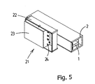
- Branching points 20 are provided on the distribution rail 1. At the location of a branching point 20 of this type, there is a cut-out in the box section, which can be covered by a shielding element made from fire-retardant material but on which in particular a branching unit 21 is mounted (Fig. 5).
- the branching unit 21 comprises a fuse box 22 which is composed of a base part and a cover part (not shown here).
- Each protection element is at one end electrically conductively connected to an associated conduction part of the distribution rail 1. At the other end, each protection element is connected to the connection element 24 which is intended for connection to a power supply cable which can be guided into the fuse box 22.
- the distribution rail 1 shown here is characterized by a sandwich structure of electrical conduction bars which are separated from one another by insulation material. This assembly of conduction bars which are insulated from one another is reinforced by two C-shaped metal profiled sections, with the result that the overall distribution rail 1 has an I profile, as seen in cross section.
- the control unit is used to process signals from the temperature sensors of the detection means and to convert these signals into control signals for the ventilation means 5 and the valve 6. In this way, the temperature profile in the distribution rail 1 can be accurately monitored and, if desired, adjusted by means of passing more or less ambient air along it.
- the control unit can switch off the ventilation means 5 in the event of fire, in order to prevent fresh oxygen from being supplied to the fire, or to reverse the direction of the ventilation means 5 in order as far as possible to suck the air out of the box section.
- the box section 2 and the branching units 21 connected to it form a closed system which has a high IP rating and is virtually airtight.
- the gas it is possible for the gas to be passed through the box section 2 at a slight excess pressure and at a mean air flow rate of a few metres per second. In normal operation, this ensures that the distribution rail 1 is able to maintain its normal temperature and that in the event of disasters or in the event of a fire, an increased air flow and therefore a greater cooling capacity can be applied to the distribution rail 1 and the signal cables 14 by the ventilation means 5.
- the system according to the invention is of great length, it is possible to opt for the supply of gas to be effected at a number of locations in the box section 2.
- a cascade supply is possible by increasing the size of the outlet openings in the line 3 the further away they are from the ventilation means 5.
- the ventilation means may pass gas directly into the clear space around the distribution rail. It is also possible for the gas to be routed in particular through the compartment in which the cables are located. Furthermore, it is possible to provide, instead of a cooling line, outlet nozzles at fixed intervals which open out in the box section and are each connected to the ventilation means. It is also possible for the detection means to be provided at other locations along the distribution rail and/or box section. Furthermore, the box section and the distribution rail may be of other desired shapes.
- the result is an efficient and reliable electrical supply and distribution system with a preservation function.
- the distribution rail is easy to monitor and keep at the required temperature.
- the system is relatively inexpensive to produce and can advantageously be used to power lighting, fans, pumps and all other systems which are to be electrically powered in a building, tunnel or other applications for objects which have to comply with what is known as a function retention standard.
- Full expansion to, for example, a disaster management system in a tunnel or building is readily possible, partly on account of the installed detection means and the communication means for them leading to the control unit.
Landscapes
- Engineering & Computer Science (AREA)
- Architecture (AREA)
- Civil Engineering (AREA)
- Structural Engineering (AREA)
- Fire-Extinguishing By Fire Departments, And Fire-Extinguishing Equipment And Control Thereof (AREA)
- Fire Alarms (AREA)
- Connection Or Junction Boxes (AREA)
Applications Claiming Priority (2)
| Application Number | Priority Date | Filing Date | Title |
|---|---|---|---|
| NL1024381A NL1024381C1 (nl) | 2003-09-25 | 2003-09-25 | Elektrisch distributie- en verdeelsysteem met ventilatiemiddelen. |
| NL1024381 | 2003-09-25 |
Publications (2)
| Publication Number | Publication Date |
|---|---|
| EP1519464A2 true EP1519464A2 (de) | 2005-03-30 |
| EP1519464A3 EP1519464A3 (de) | 2006-04-26 |
Family
ID=34192313
Family Applications (1)
| Application Number | Title | Priority Date | Filing Date |
|---|---|---|---|
| EP04077649A Withdrawn EP1519464A3 (de) | 2003-09-25 | 2004-09-23 | Elektrisches Versorgungs- und Verteilungssystem mit Belüftungseinrichtung |
Country Status (2)
| Country | Link |
|---|---|
| EP (1) | EP1519464A3 (de) |
| NL (1) | NL1024381C1 (de) |
Family Cites Families (3)
| Publication number | Priority date | Publication date | Assignee | Title |
|---|---|---|---|---|
| US5306165A (en) * | 1993-01-27 | 1994-04-26 | Jacques Nadeau | Electric distributing system |
| FR2715777B1 (fr) * | 1994-01-28 | 1996-04-05 | Amco | Dispositif de protection de câbles électriques. |
| DE10065166C1 (de) * | 2000-12-23 | 2002-07-11 | Gabo Systemtech Gmbh | Installationskanal |
-
2003
- 2003-09-25 NL NL1024381A patent/NL1024381C1/nl not_active IP Right Cessation
-
2004
- 2004-09-23 EP EP04077649A patent/EP1519464A3/de not_active Withdrawn
Also Published As
| Publication number | Publication date |
|---|---|
| NL1024381C1 (nl) | 2005-03-29 |
| EP1519464A3 (de) | 2006-04-26 |
Similar Documents
| Publication | Publication Date | Title |
|---|---|---|
| US20140043802A1 (en) | Linear led system | |
| JP2009171833A (ja) | スイッチギヤ | |
| WO2013074804A1 (en) | Overheat suppression systems and methods for an electrical housing | |
| CA2255979A1 (en) | Means and method for extinguishing a fire in at least one cable duct | |
| CN106058702A (zh) | 一种模块化智能箱式变电站 | |
| CN108828400A (zh) | 一种母线槽智能监测系统 | |
| US6399875B1 (en) | Lightning protected housing structure | |
| CN216599133U (zh) | 一种开关柜运行状态监测诊断系统 | |
| CN214206138U (zh) | 一种具有监测功能的plc控制柜 | |
| KR102113073B1 (ko) | 개량된 전주 장착용 소형 분배중계기함 | |
| CN104505721B (zh) | 一种易清理配电箱 | |
| CN205104777U (zh) | 防雷配电柜 | |
| KR102596782B1 (ko) | 건축물 실내전기 수배전반의 절연과 불연 기능을 갖춘 인입선 보호커버 구조 | |
| RU2699667C1 (ru) | Устройство наружной установки для плавки гололеда | |
| CN215120019U (zh) | 一种具有预警功能的智能母线槽 | |
| CN210041091U (zh) | 一种紧凑型光伏发电系统开关站 | |
| NL1024381C1 (nl) | Elektrisch distributie- en verdeelsysteem met ventilatiemiddelen. | |
| CN111273412A (zh) | 一种便于束线具有保护结构的宽带配线箱 | |
| RU2128535C1 (ru) | Пожарный сигнализатор | |
| KR101853925B1 (ko) | 화재감지기 구조체 및 그 설치 방법 | |
| US7812720B2 (en) | Apparatus and method for monitoring a component of a wireless communication network to determine whether the component has been tampered with, disabled and/or removed | |
| CN216486724U (zh) | 一种电智慧火灾监测控制设备 | |
| CN214044531U (zh) | 一种油田配电箱 | |
| CN214545135U (zh) | 一种高防护性能户外机柜 | |
| CN108171918A (zh) | 一种高压输变电火灾预警装置 |
Legal Events
| Date | Code | Title | Description |
|---|---|---|---|
| PUAI | Public reference made under article 153(3) epc to a published international application that has entered the european phase |
Free format text: ORIGINAL CODE: 0009012 |
|
| AK | Designated contracting states |
Kind code of ref document: A2 Designated state(s): AT BE BG CH CY CZ DE DK EE ES FI FR GB GR HU IE IT LI LU MC NL PL PT RO SE SI SK TR |
|
| AX | Request for extension of the european patent |
Extension state: AL HR LT LV MK |
|
| PUAL | Search report despatched |
Free format text: ORIGINAL CODE: 0009013 |
|
| AK | Designated contracting states |
Kind code of ref document: A3 Designated state(s): AT BE BG CH CY CZ DE DK EE ES FI FR GB GR HU IE IT LI LU MC NL PL PT RO SE SI SK TR |
|
| AX | Request for extension of the european patent |
Extension state: AL HR LT LV MK |
|
| AKX | Designation fees paid | ||
| REG | Reference to a national code |
Ref country code: DE Ref legal event code: 8566 |
|
| STAA | Information on the status of an ep patent application or granted ep patent |
Free format text: STATUS: THE APPLICATION IS DEEMED TO BE WITHDRAWN |
|
| 18D | Application deemed to be withdrawn |
Effective date: 20061027 |