EP1519428B1 - Lithium Secondary Battery with high safety and manufacturing method thereof - Google Patents
Lithium Secondary Battery with high safety and manufacturing method thereof Download PDFInfo
- Publication number
- EP1519428B1 EP1519428B1 EP04253264A EP04253264A EP1519428B1 EP 1519428 B1 EP1519428 B1 EP 1519428B1 EP 04253264 A EP04253264 A EP 04253264A EP 04253264 A EP04253264 A EP 04253264A EP 1519428 B1 EP1519428 B1 EP 1519428B1
- Authority
- EP
- European Patent Office
- Prior art keywords
- lithium secondary
- package
- secondary battery
- outermost layer
- electrode assembly
- Prior art date
- Legal status (The legal status is an assumption and is not a legal conclusion. Google has not performed a legal analysis and makes no representation as to the accuracy of the status listed.)
- Active
Links
Images


Classifications
-
- H—ELECTRICITY
- H01—ELECTRIC ELEMENTS
- H01M—PROCESSES OR MEANS, e.g. BATTERIES, FOR THE DIRECT CONVERSION OF CHEMICAL ENERGY INTO ELECTRICAL ENERGY
- H01M10/00—Secondary cells; Manufacture thereof
- H01M10/04—Construction or manufacture in general
- H01M10/0431—Cells with wound or folded electrodes
-
- H—ELECTRICITY
- H01—ELECTRIC ELEMENTS
- H01M—PROCESSES OR MEANS, e.g. BATTERIES, FOR THE DIRECT CONVERSION OF CHEMICAL ENERGY INTO ELECTRICAL ENERGY
- H01M50/00—Constructional details or processes of manufacture of the non-active parts of electrochemical cells other than fuel cells, e.g. hybrid cells
- H01M50/10—Primary casings, jackets or wrappings of a single cell or a single battery
- H01M50/116—Primary casings, jackets or wrappings of a single cell or a single battery characterised by the material
- H01M50/117—Inorganic material
- H01M50/119—Metals
-
- H—ELECTRICITY
- H01—ELECTRIC ELEMENTS
- H01M—PROCESSES OR MEANS, e.g. BATTERIES, FOR THE DIRECT CONVERSION OF CHEMICAL ENERGY INTO ELECTRICAL ENERGY
- H01M50/00—Constructional details or processes of manufacture of the non-active parts of electrochemical cells other than fuel cells, e.g. hybrid cells
- H01M50/10—Primary casings, jackets or wrappings of a single cell or a single battery
- H01M50/116—Primary casings, jackets or wrappings of a single cell or a single battery characterised by the material
- H01M50/121—Organic material
-
- H—ELECTRICITY
- H01—ELECTRIC ELEMENTS
- H01M—PROCESSES OR MEANS, e.g. BATTERIES, FOR THE DIRECT CONVERSION OF CHEMICAL ENERGY INTO ELECTRICAL ENERGY
- H01M50/00—Constructional details or processes of manufacture of the non-active parts of electrochemical cells other than fuel cells, e.g. hybrid cells
- H01M50/10—Primary casings, jackets or wrappings of a single cell or a single battery
- H01M50/116—Primary casings, jackets or wrappings of a single cell or a single battery characterised by the material
- H01M50/124—Primary casings, jackets or wrappings of a single cell or a single battery characterised by the material having a layered structure
- H01M50/126—Primary casings, jackets or wrappings of a single cell or a single battery characterised by the material having a layered structure comprising three or more layers
-
- H—ELECTRICITY
- H01—ELECTRIC ELEMENTS
- H01M—PROCESSES OR MEANS, e.g. BATTERIES, FOR THE DIRECT CONVERSION OF CHEMICAL ENERGY INTO ELECTRICAL ENERGY
- H01M50/00—Constructional details or processes of manufacture of the non-active parts of electrochemical cells other than fuel cells, e.g. hybrid cells
- H01M50/10—Primary casings, jackets or wrappings of a single cell or a single battery
- H01M50/131—Primary casings, jackets or wrappings of a single cell or a single battery characterised by physical properties, e.g. gas-permeability or size
- H01M50/133—Thickness
-
- H—ELECTRICITY
- H01—ELECTRIC ELEMENTS
- H01M—PROCESSES OR MEANS, e.g. BATTERIES, FOR THE DIRECT CONVERSION OF CHEMICAL ENERGY INTO ELECTRICAL ENERGY
- H01M50/00—Constructional details or processes of manufacture of the non-active parts of electrochemical cells other than fuel cells, e.g. hybrid cells
- H01M50/20—Mountings; Secondary casings or frames; Racks, modules or packs; Suspension devices; Shock absorbers; Transport or carrying devices; Holders
- H01M50/204—Racks, modules or packs for multiple batteries or multiple cells
- H01M50/207—Racks, modules or packs for multiple batteries or multiple cells characterised by their shape
- H01M50/211—Racks, modules or packs for multiple batteries or multiple cells characterised by their shape adapted for pouch cells
-
- H—ELECTRICITY
- H01—ELECTRIC ELEMENTS
- H01M—PROCESSES OR MEANS, e.g. BATTERIES, FOR THE DIRECT CONVERSION OF CHEMICAL ENERGY INTO ELECTRICAL ENERGY
- H01M50/00—Constructional details or processes of manufacture of the non-active parts of electrochemical cells other than fuel cells, e.g. hybrid cells
- H01M50/20—Mountings; Secondary casings or frames; Racks, modules or packs; Suspension devices; Shock absorbers; Transport or carrying devices; Holders
- H01M50/233—Mountings; Secondary casings or frames; Racks, modules or packs; Suspension devices; Shock absorbers; Transport or carrying devices; Holders characterised by physical properties of casings or racks, e.g. dimensions
- H01M50/24—Mountings; Secondary casings or frames; Racks, modules or packs; Suspension devices; Shock absorbers; Transport or carrying devices; Holders characterised by physical properties of casings or racks, e.g. dimensions adapted for protecting batteries from their environment, e.g. from corrosion
-
- H—ELECTRICITY
- H01—ELECTRIC ELEMENTS
- H01M—PROCESSES OR MEANS, e.g. BATTERIES, FOR THE DIRECT CONVERSION OF CHEMICAL ENERGY INTO ELECTRICAL ENERGY
- H01M50/00—Constructional details or processes of manufacture of the non-active parts of electrochemical cells other than fuel cells, e.g. hybrid cells
- H01M50/50—Current conducting connections for cells or batteries
- H01M50/543—Terminals
- H01M50/547—Terminals characterised by the disposition of the terminals on the cells
- H01M50/55—Terminals characterised by the disposition of the terminals on the cells on the same side of the cell
-
- H—ELECTRICITY
- H01—ELECTRIC ELEMENTS
- H01M—PROCESSES OR MEANS, e.g. BATTERIES, FOR THE DIRECT CONVERSION OF CHEMICAL ENERGY INTO ELECTRICAL ENERGY
- H01M50/00—Constructional details or processes of manufacture of the non-active parts of electrochemical cells other than fuel cells, e.g. hybrid cells
- H01M50/50—Current conducting connections for cells or batteries
- H01M50/543—Terminals
- H01M50/552—Terminals characterised by their shape
- H01M50/553—Terminals adapted for prismatic, pouch or rectangular cells
- H01M50/557—Plate-shaped terminals
-
- H—ELECTRICITY
- H01—ELECTRIC ELEMENTS
- H01M—PROCESSES OR MEANS, e.g. BATTERIES, FOR THE DIRECT CONVERSION OF CHEMICAL ENERGY INTO ELECTRICAL ENERGY
- H01M50/00—Constructional details or processes of manufacture of the non-active parts of electrochemical cells other than fuel cells, e.g. hybrid cells
- H01M50/50—Current conducting connections for cells or batteries
- H01M50/543—Terminals
- H01M50/562—Terminals characterised by the material
-
- H—ELECTRICITY
- H01—ELECTRIC ELEMENTS
- H01M—PROCESSES OR MEANS, e.g. BATTERIES, FOR THE DIRECT CONVERSION OF CHEMICAL ENERGY INTO ELECTRICAL ENERGY
- H01M50/00—Constructional details or processes of manufacture of the non-active parts of electrochemical cells other than fuel cells, e.g. hybrid cells
- H01M50/10—Primary casings, jackets or wrappings of a single cell or a single battery
- H01M50/116—Primary casings, jackets or wrappings of a single cell or a single battery characterised by the material
- H01M50/124—Primary casings, jackets or wrappings of a single cell or a single battery characterised by the material having a layered structure
-
- Y—GENERAL TAGGING OF NEW TECHNOLOGICAL DEVELOPMENTS; GENERAL TAGGING OF CROSS-SECTIONAL TECHNOLOGIES SPANNING OVER SEVERAL SECTIONS OF THE IPC; TECHNICAL SUBJECTS COVERED BY FORMER USPC CROSS-REFERENCE ART COLLECTIONS [XRACs] AND DIGESTS
- Y02—TECHNOLOGIES OR APPLICATIONS FOR MITIGATION OR ADAPTATION AGAINST CLIMATE CHANGE
- Y02E—REDUCTION OF GREENHOUSE GAS [GHG] EMISSIONS, RELATED TO ENERGY GENERATION, TRANSMISSION OR DISTRIBUTION
- Y02E60/00—Enabling technologies; Technologies with a potential or indirect contribution to GHG emissions mitigation
- Y02E60/10—Energy storage using batteries
-
- Y—GENERAL TAGGING OF NEW TECHNOLOGICAL DEVELOPMENTS; GENERAL TAGGING OF CROSS-SECTIONAL TECHNOLOGIES SPANNING OVER SEVERAL SECTIONS OF THE IPC; TECHNICAL SUBJECTS COVERED BY FORMER USPC CROSS-REFERENCE ART COLLECTIONS [XRACs] AND DIGESTS
- Y02—TECHNOLOGIES OR APPLICATIONS FOR MITIGATION OR ADAPTATION AGAINST CLIMATE CHANGE
- Y02P—CLIMATE CHANGE MITIGATION TECHNOLOGIES IN THE PRODUCTION OR PROCESSING OF GOODS
- Y02P70/00—Climate change mitigation technologies in the production process for final industrial or consumer products
- Y02P70/50—Manufacturing or production processes characterised by the final manufactured product
-
- Y—GENERAL TAGGING OF NEW TECHNOLOGICAL DEVELOPMENTS; GENERAL TAGGING OF CROSS-SECTIONAL TECHNOLOGIES SPANNING OVER SEVERAL SECTIONS OF THE IPC; TECHNICAL SUBJECTS COVERED BY FORMER USPC CROSS-REFERENCE ART COLLECTIONS [XRACs] AND DIGESTS
- Y10—TECHNICAL SUBJECTS COVERED BY FORMER USPC
- Y10T—TECHNICAL SUBJECTS COVERED BY FORMER US CLASSIFICATION
- Y10T29/00—Metal working
- Y10T29/49—Method of mechanical manufacture
- Y10T29/49002—Electrical device making
- Y10T29/49108—Electric battery cell making
- Y10T29/4911—Electric battery cell making including sealing
-
- Y—GENERAL TAGGING OF NEW TECHNOLOGICAL DEVELOPMENTS; GENERAL TAGGING OF CROSS-SECTIONAL TECHNOLOGIES SPANNING OVER SEVERAL SECTIONS OF THE IPC; TECHNICAL SUBJECTS COVERED BY FORMER USPC CROSS-REFERENCE ART COLLECTIONS [XRACs] AND DIGESTS
- Y10—TECHNICAL SUBJECTS COVERED BY FORMER USPC
- Y10T—TECHNICAL SUBJECTS COVERED BY FORMER US CLASSIFICATION
- Y10T29/00—Metal working
- Y10T29/49—Method of mechanical manufacture
- Y10T29/49002—Electrical device making
- Y10T29/49108—Electric battery cell making
- Y10T29/49114—Electric battery cell making including adhesively bonding
-
- Y—GENERAL TAGGING OF NEW TECHNOLOGICAL DEVELOPMENTS; GENERAL TAGGING OF CROSS-SECTIONAL TECHNOLOGIES SPANNING OVER SEVERAL SECTIONS OF THE IPC; TECHNICAL SUBJECTS COVERED BY FORMER USPC CROSS-REFERENCE ART COLLECTIONS [XRACs] AND DIGESTS
- Y10—TECHNICAL SUBJECTS COVERED BY FORMER USPC
- Y10T—TECHNICAL SUBJECTS COVERED BY FORMER US CLASSIFICATION
- Y10T29/00—Metal working
- Y10T29/49—Method of mechanical manufacture
- Y10T29/49002—Electrical device making
- Y10T29/49108—Electric battery cell making
- Y10T29/49115—Electric battery cell making including coating or impregnating
Definitions
- the present invention relates to a lithium secondary battery, and more particularly to a lithium secondary battery capable of preventing explosion or firing caused by the increase of inner pressure due to misusage.
- portable electronic products such as a video camera, a mobile phone and a notebook computer become lighter and smaller and are designed to have various functions.
- an energy storage battery, a robot and a satellite are regularized, various research and development concerning a battery used as a power source of them have been extensively performed.
- a battery is usually made to be rechargeable and can be used continuously.
- NiCd battery nickel-cadmium battery
- NiMH battery nickel metal hydride battery
- NiZn battery nickel-zinc battery
- lithium secondary battery a lithium secondary battery or the like is used as a power source of electronic appliances, and the lithium secondary battery among them becomes generally popularized in consideration of its life cycle and capacity.
- the lithium secondary battery can be classified into a lithium metal battery and a lithium ion battery which use a liquid electrolyte, and a lithium polymer battery using a polymer solid electrolyte.
- the lithium polymer battery can also be classified into a full-solid lithium polymer battery containing no organic electrolyte and a lithium ion polymer battery using a gel polymer electrolyte containing organic electrolyte.
- the lithium secondary battery includes an electrode assembly having an anode collector (aluminum or nickel, for example), an anode active material layer (polymer anode material such as metal oxide, carbon black, metal sulfide, electrolytic liquid, and polyacrylonitrile, for example), an electrolytic layer (organic solid electrolyte or gel electrolyte derived from lithium salt or carbonate electrolytic liquid such as propylene carbonate, ethylene carbonate, dimethyl carbonate, and ethylene methylcarbonate), a cathode active material (polymer cathode material such as lithium metal, alloys, carbon, electrolytic liquid, and polyacrylonitrile), and a cathode collector (copper, nickel or stainless steel); and a case for packaging the electrode assembly.
- anode collector aluminum or nickel, for example
- an anode active material layer polymer anode material such as metal oxide, carbon black, metal sulfide, electrolytic liquid, and polyacrylonitrile
- an electrolytic layer organic solid electro
- the lithium secondary battery generally uses Li-metal or carbon materials for the cathode active material.
- Li-metal may cause explosion due to a short circuit of the battery caused by formation of resin dentrite when being used as a cathode material
- Li-metal becomes substituted with carbon materials.
- the anode active material generally adopts Li-metal oxide, for example complex metal oxides such as LiMn 2 O 4 LiMnO 2 , LiCoO 2 , LiNiO 2 , LiNi 1-x Co x O 2 (0 ⁇ x ⁇ 1).
- Electrode materials in Mn group such as LiMn 2 O 4 and LiMnO 2 are advantageous in that they are easily composed, relatively inexpensive, and less causing pollution to environments, but they disadvantageously have small discharging capacity.
- LiCoO 2 shows good electric conductivity, high battery voltage and excellent electrode characteristics, and it is a typical anode electrode material manufactured and marketed by many companies like Sony.
- LicoO 2 has a disadvantage of high price.
- LiNiO 2 is relatively inexpensive among the mentioned anode electrode materials and shows the highest discharging capacity.
- LiNiO 2 is not easily composed, and the high discharging capacity may spoil the stability of battery.
- the battery shows its characteristics through complex reactions of anode/electrolyte, cathode/electrolyte and so on
- one of main factors for improving performance of the battery is to use suitable electrolyte.
- the role of electrolyte is just expected as a medium for moving lithium ions, and the electrolyte is used only for that purpose.
- the carbonate solvent is known as most suitable for electrolyte of the high-potential lithium secondary battery, thereby widely used now.
- this electrolyte has a disadvantage that it may be easily fired due to external factors or at high temperature since the electrolyte is organic solvent.
- the sealed battery using organic solvent and having high energy density breakdown, overcharging or misuse of relevant machinery including a charger may cause chemical reaction, thereby generating abnormal gas in the battery.
- This abnormal gas makes the inner pressure of the battery be excessive, thereby resulting in accidents such as breakage of the battery due to the excessive pressure in the battery or damage on an electronic equipment using the battery as a power source.
- the method is either mixing an overcharging restrainer into electrolyte or using an explosion-proof safety device.
- a phosphatic solvent is additionally added to a carbonate solvent.
- This method shows an improvement feature in stability, but shows problems in the fundamental battery performance like the increase of irreversible capacity and the deterioration of life cycle.
- the resolution of the phosphatic solvent increases the irreversible capacity excessively during the charging/discharging, so the battery performance is significantly deteriorated.
- an explosion-proof safety device which opens a valve or breaks up the case when the inner pressure in the battery exceeds a set value is already used.
- an important problem to be solved for the explosion-proof safety device is accurate control, namely controlling the valve to be accurately opened or the case to be broken up as desired, when the inner pressure reaches a set value.
- the valve should not be opened before the inner pressure reaches a set value and the value should be opened if the inner pressure of the battery reaches the set value.
- the explosion-proof safety device requires much time and cost for production of batteries.
- Japanese Patent Laid-open Publication Heisei 6-196150 discloses a device having a conductive partition deformed vertically and sealing the battery, and a welding plate welded to the partition in connection with a lead. In the device, the increase of an inner pressure makes the partition expanded, so a welding point of the partition is separated from the welding plate to cut off electricity.
- this explosion-proof safety device requires that the partition and the welding plate be welded at a low temperature so that they may be separated at a certain inner pressure.
- the supersonic welding which allows welding with low strength is used.
- the supersonic welding however just fuses the surface of the welding point by means of vibration heating, so the welding strength is seriously irregular.
- the above-mentioned explosion-proof safety device sets an electricity cutoff pressure depending on the wending strength of the welding point, the electricity cutoff pressure is changed according to such irregular welding strength.
- the electricity may be cut off before the inner pressure of the battery reaches a predetermined level, or contrarily, the electricity may not be cut off though the inner pressure of the battery exceeds a predetermined level.
- Document JP2003/203612 discloses a dry cell battery with an adhesive layer on the package, and on which adhesive layer further layers are laminated.
- the present invention is designed to solve such problems of the prior art, and therefore it is an object of the present invention to provide a lithium secondary battery having high stability with simple configuration requiring low costs, and its manufacturing method.
- the present invention provides a lithium secondary battery which includes an electrode assembly having an anode plate, a cathode plate and a separator; a package having a receiving portion for receiving the electrode assembly, the receiving portion being sealed and filled with electrolyte together with the electrode assembly; and an outermost layer at least partially formed on an outer surface of the package wherein the outermost layer is comprised of an adhesive.
- the outermost layer is preferably made of one selected from the group consisting of acrylic resin, EVA (Ethylene Vinyl Acetate) resin, polyamide resin, and rubber.
- the separator is made of a single sheet, folded in a shape of fold-to-fold, and the electrode assembly is configured so that a plurality of the anode plates and a plurality of the cathode plates are laminated in turns with the folded separated being interposed therebetween.
- a set battery in which a plurality of the lithium secondary batteries mentioned above are connected in parallel or in series, and a plurality of the lithium secondary batteries connected in parallel or in series are put into a pack having anode and cathode terminals.
- the present invention also provides a method for manufacturing a lithium secondary battery which includes the steps of: (a) preparing an electrode assembly having an anode plate, a cathode plate and a separator; (b) putting the electrode assembly into a package together with electrolyte and then sealing the package; (c) forming an outermost layer at least partially on an outer surface of the package the outermost layer being comprised of an adhesive; and (d) curing the outermost layer.
- a method for manufacturing a lithium secondary battery which includes the step of: (a) preparing an electrode assembly having an anode plate, a cathode plate and a separator; (b) making a plurality of single batteries by putting the electrode assembly into each package together with electrolyte and then sealing the package; (c) making a set battery by connecting a plurality of the single batteries in parallel or in series; (d) putting the set battery into a pack having anode and cathode terminals; (e) forming an outermost layer at least partially on an outer surface of the set package the outermost layer being comprised of an adhesive; and (f) curing the outermost layer.
- the outermost layer is preferably made of one selected from the group consisting of acrylic resin, EVA resin, polyamide resin, and rubber, and the adhesive layer is formed either by coating or spraying an emulsion or paste adhesive on the outer surface of the package or by soaking the sealed package in an emulsion or paste adhesive.
- FIG. 1 is a perspective view showing an electrode assembly of a lithium secondary battery according to a preferred embodiment of the present invention
- FIG. 2a is a partial sectional view schematically showing a dissembled state of the electrode assembly of FIG. 1
- FIG. 2b is a plane view showing anode and cathode plates of FIG. 2a .
- the lithium secondary battery of this embodiment includes an electrode assembly 100 as shown in FIG. 1 , a package 20 (see FIGs. 3 to 5 ) for receiving and sealing the electrode assembly 100, and an adhesive layer 30 (see FIGs. 6a to 6c ) formed and cured on the surface of the package 20.
- the electrode assembly 100 may be theoretically a lithium secondary ion battery or a lithium secondary polymer battery.
- the electrode assembly 100 may be any of a unit cell in which an anode plate 15a, a separator 10 and a cathode plate 15b are laminated in order, and a Bi-cell in which they are laminated in order of the anode plate 15a, the separator 10, the cathode plate 15b, the separator 10, the anode plate 15a, the separator 10 and the cathode plate 15b.
- a unit cell or a Bi-cell may be piled up to have multi layers.
- Each of the anode plate 15a and the cathode plate 15b is composed of a plate body and an anode or cathode grid 16a or 16b protruded from the plate body.
- the anode and cathode grids 16a and 16b may be arranged to be opposite to each other on the basis of a longitudinal direction of the electrode assembly 100, but preferably the anode and cathode grids 16a and 16b are positioned toward the same direction on the basis of a longitudinal direction of the electrode assembly 100.
- the anode/cathode grid 16a or 16b of the anode/cathode plate 15a or 15b is respectively connected to an anode tap 18a or a cathode tap 18b by means of welding or the like.
- the electrode assembly 100 is distinguished from the battery, in itself, in which the electrode assembly 100 is received in the package 20, and the package 20 is filled with electrolyte liquid (not shown) and hermetically sealed.
- the electrode assembly may have any of various structures described above, the electrode assembly 100 of the present invention preferably has a laminated structure in a shape of fold-to-fold in which a plurality of anode plates 15a and a plurality of cathode plates 15b are alternatively laminated with a sheet-shaped separator 10 being interposed therebetween. The fold-to-fold shape of the electrode assembly 100 is now described.
- the anode plate 15a is fabricated by coating anode active material on one or both faces of a foil collector, for example an aluminum foil collector, and then drying the anode active material.
- the anode grid 16a is protruded at a region of the collector where the anode active material is not coated.
- the cathode plate 15b is fabricated by coating cathode active material on one or both faces of a foil collector, for example a copper foil collector, and then drying the cathode active material.
- the cathode grid 16b is protruded at a region of the collector where the cathode active material is not coated.
- the separator 10 has a porous polymer film made of polyethylene (PE) or polypropylene (PP), and has a single-layered or multi-layered structure.
- the separator 10 includes adhesion portions to which the anode and cathode plates 15a and 15b are respectively adhered, an insulation portion for insulating the anode and cathode plates 15a and 15b between the adhesion portions, and a winding portion for winding several times the surface of a lamination in which the anode/cathode plates are laminated.
- the adhesion portion and the insulation portion are formed in order, and the insulation portion has a length slightly longer than that of the adhesion portion.
- the insulation portion Since the insulation portion is folded at a side of the anode/cathode plate 15a and 15b, the insulation portion should have an additional length at least as much as the thickness of the anode/cathode plate 15a and 15b, while the adhesion portion may have a length identical to the width of the anode plate 15a and the cathode plate 15b.
- the winding portion preferably has a length sufficient for winding the lamination.
- the ion-conductive polymer adhesive employs an SBR Latex adhesive, an acrylic solvent adhesive, an adhesive using PAN (homo, co-polymer), an adhesive using PAN/PVDF (Polyvinylidene Fluoride) blending, an solvent-type adhesive using MMA (Methyl Methacrylate)/PMMA (Poly Methyl Methacrylate), and so on.
- the separator 10 is formed in a zigzag shape (more specifically, in a fold-to-fold shape) so that the anode and cathode plates are alternated), and then fixed by a tape 12 for convenience of subsequent processes.
- the electrode assembly 100 prepared as above is then received in the package 20 together with electrolyte (not shown), and then sealed to make a single battery of the lithium secondary battery 200, as shown in FIGs. 3 to 5 .
- the package 20 is preferably a pouch package made of lamination of aluminum and sealant.
- the package 20 is also preferably an embossing-type package having a concave portion (or, a receiving portion, 22) formed by pressing the lamination so that the electrode assembly is received in the receiving portion 22.
- the embossing-type package may give more compact packaging, compared with the pouch package.
- the package 20 is preferably made of a thin aluminum having a thickness of about 20 to 50 ⁇ m.
- Polypropylene having a thickness of about 30 ⁇ m is laminated by means of adhesive on the inner surface of the package 20, namely on the surface toward the electrode assembly 100 received therein.
- a nylon film is laminated by means of adhesive on the outer surface of the aluminum.
- the outer surface of the single-type lithium secondary battery 200, the outer surface of the package 20, is coated with the adhesive layer 30.
- the kind of the adhesive layer 30 used in this case is not limited if it is capable of fixing on the outer surface of the package 20, but the adhesive layer 30 preferably employs acryl resin, EVA (ethylene vinyl acetate) resin, polyamide resin or rubber.
- the adhesive layer 30 is preferably in an emulsion or paste state when coated for safe coating.
- an emulsion or paste adhesive is smeared on the outer surface of the lithium secondary battery 200 by using a roller 32 as shown in FIG. 6a , or a sprayer 34 is used for coating the adhesive as shown in FIG. 6b .
- a sprayer 34 is used for coating the adhesive as shown in FIG. 6b .
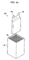
- FIG. 6c it is also possible to soak the lithium secondary battery 200 into a container 36 containing the adhesive in order to coat the adhesive layer 30 on the lithium secondary battery 200.
- the pattern or thickness of the adhesive layer 30 may be selected variously. That is, the adhesive may be coated over the entire surface of the package 20 with a regular thickness, or may be coated partially thereon.
- the pattern or thickness of the adhesive layer 30 may be suitably selected on consideration of the cohesive power of the cured adhesive layer and the desired inner pressure of the battery.
- the coated adhesive layer 30 is cured.
- the adhesive layer 30 is either heated at a suitable temperature for a suitable time or dried naturally without heating depending on the kind of the used adhesive. In some cases, the adhesive layer 30 may be cured by radiating ultraviolet rays thereto.
- the adhesive layer 30 formed and cured as described above functions as an explosion-proof safety device for preventing firing or explosion of the lithium secondary battery 200.
- the adhesive layer 30 having strong cohesive force suitably restrains the shrinkage or expansion of the package 20, thereby controlling breakage of the package 20 or breakdown of the seal and reducing the area of the electrode assembly to be contacted with atmosphere when the seal is broken down.
- firing or explosion of the battery may be prevented.
- the lithium secondary battery of the present invention may be configured into a set battery in which a plurality of single batteries are connected in series or in parallel.
- the single batteries 200 are put into a case or a pack with their anode and cathode taps 18a and taps 18b being connected in parallel or in series. Or else, as shown in FIGs.
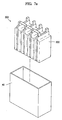
- a set battery 300 in which a plurality of single batteries 200 having no adhesive layer are connected in series or in parallel is put into the pack 40 together with adhesive, and then the set battery 300 is packaged with its anode and cathode taps being respectively connected to an anode terminal 44a and a cathode terminal 44b of a cover 44.
- the processes of connecting the anode/cathode taps 18a and 18b of the single battery 200 in series or in parallel, receiving the battery 200 or 300 into the pack 40 and forming the adhesive layer 30 may be suitably changed according to the manufacturing procedure of the set battery.
- the lithium secondary battery manufactured as described above is overcharged, and its results are examined.
- the lithium secondary battery 200 (a single battery having a regular voltage of 4.2V and a capacity of 3.3Ah) as shown in FIG. 5 is prepared.
- An acrylic resin in an emulsion state is coated on the lithium secondary battery 200 by soaking the battery 200 into the resin and then dried, three times, to prepare two samples having the adhesive layer 30 for the following experiments 1 and 2. After that, two samples are overcharged under the conditions of a charging rate of 1C and a voltage of 30V.
- Table 1 Samples Weight of battery Thickness of battery Charging conditions Results Before coating After coating Before coating After coating After coating Experiment 1 65.4g 72.6g 5.4mm 7.7mm 1C / 30V no explosion or firing Experiment 2 65.3g 73.0g 5.3mm 7.8mm
- FIGs. 8a to 8c are graphs showing the change of an electric current, a voltage and a temperature according to a charging time of the lithium secondary batteries according to the experiments 1 and 2, respectively. Showing the graphs, it will be known that the electric current reaches 0A and the voltage reaches 30V at the instant that the charging time exceeds 150 minutes, so the batteries cannot be used any more. However, even in this state, the packages are no more than somewhat wrinkled with no explosion or firing.
- the same single battery as shown in FIG. 5 without an adhesive layer is prepared as a comparative example, and then overcharged under the same condition as above.
- the voltage goes over 5.8V
- gas is generated in the battery to make the package expanded.
- the package is exploded with a voltage of about 6V.
- the adhesive layer formed on the surface of the package of the battery acts a role of preventing firing or explosion of the battery by controlling expansion of the package due to its strong cohesive force.
- the lithium secondary battery described above may prevent its package from exploding due to abrupt breakage of the package when the package is expanded due to the increase of inner pressure of the battery over a critical value by forming an adhesive layer having strong cohesive force on the outer surface of the package.
- the present invention may realize an explosion-proof safety function with a much simpler structure at a much smaller cost than the conventional complicated explosion-proof safety device.
Description
- The present invention relates to a lithium secondary battery, and more particularly to a lithium secondary battery capable of preventing explosion or firing caused by the increase of inner pressure due to misusage.
- Generally, portable electronic products such as a video camera, a mobile phone and a notebook computer become lighter and smaller and are designed to have various functions. In addition, as an electric automobile, an energy storage battery, a robot and a satellite are regularized, various research and development concerning a battery used as a power source of them have been extensively performed. Such a battery is usually made to be rechargeable and can be used continuously.
- Usually, a nickel-cadmium battery (NiCd battery), a nickel metal hydride battery (NiMH battery), a nickel-zinc battery (NiZn battery), a lithium secondary battery or the like is used as a power source of electronic appliances, and the lithium secondary battery among them becomes generally popularized in consideration of its life cycle and capacity.
- According to the kind of electrolyte, the lithium secondary battery can be classified into a lithium metal battery and a lithium ion battery which use a liquid electrolyte, and a lithium polymer battery using a polymer solid electrolyte. Depending on the kind of polymer solid electrolyte, the lithium polymer battery can also be classified into a full-solid lithium polymer battery containing no organic electrolyte and a lithium ion polymer battery using a gel polymer electrolyte containing organic electrolyte.
- The lithium secondary battery includes an electrode assembly having an anode collector (aluminum or nickel, for example), an anode active material layer (polymer anode material such as metal oxide, carbon black, metal sulfide, electrolytic liquid, and polyacrylonitrile, for example), an electrolytic layer (organic solid electrolyte or gel electrolyte derived from lithium salt or carbonate electrolytic liquid such as propylene carbonate, ethylene carbonate, dimethyl carbonate, and ethylene methylcarbonate), a cathode active material (polymer cathode material such as lithium metal, alloys, carbon, electrolytic liquid, and polyacrylonitrile), and a cathode collector (copper, nickel or stainless steel); and a case for packaging the electrode assembly.
- The lithium secondary battery generally uses Li-metal or carbon materials for the cathode active material. However, since Li-metal may cause explosion due to a short circuit of the battery caused by formation of resin dentrite when being used as a cathode material, Li-metal becomes substituted with carbon materials. The anode active material generally adopts Li-metal oxide, for example complex metal oxides such as LiMn2O4 LiMnO2, LiCoO2, LiNiO2, LiNi1-xCoxO2 (0<x<1). Electrode materials in Mn group such as LiMn2O4 and LiMnO2 are advantageous in that they are easily composed, relatively inexpensive, and less causing pollution to environments, but they disadvantageously have small discharging capacity. Particularly, in case of LiMn2O4, LiCoO2 and LiNiO2, the discharging capacity is smaller than that of other active materials, the discharging capacity is abruptly reduced in charging/discharging, and the life of the battery is seriously deteriorated due to elution of manganese when charging/discharging is continued at high temperature. LiCoO2 shows good electric conductivity, high battery voltage and excellent electrode characteristics, and it is a typical anode electrode material manufactured and marketed by many companies like Sony. However, LicoO2 has a disadvantage of high price. LiNiO2 is relatively inexpensive among the mentioned anode electrode materials and shows the highest discharging capacity. However, LiNiO2 is not easily composed, and the high discharging capacity may spoil the stability of battery.
- On the other hand, since the battery shows its characteristics through complex reactions of anode/electrolyte, cathode/electrolyte and so on, one of main factors for improving performance of the battery is to use suitable electrolyte. Conventionally, the role of electrolyte is just expected as a medium for moving lithium ions, and the electrolyte is used only for that purpose. Recently, it has been revealed that the electrolyte may be resolved during the charging/discharging of battery, and this resolving is fatal to the performance of battery. Accordingly, the carbonate solvent is known as most suitable for electrolyte of the high-potential lithium secondary battery, thereby widely used now. However, this electrolyte has a disadvantage that it may be easily fired due to external factors or at high temperature since the electrolyte is organic solvent.
- For the sealed battery using organic solvent and having high energy density, breakdown, overcharging or misuse of relevant machinery including a charger may cause chemical reaction, thereby generating abnormal gas in the battery. This abnormal gas makes the inner pressure of the battery be excessive, thereby resulting in accidents such as breakage of the battery due to the excessive pressure in the battery or damage on an electronic equipment using the battery as a power source. Thus, a method for improving stability of the lithium secondary battery by preventing such accidents is vigorously researched. Representatively, the method is either mixing an overcharging restrainer into electrolyte or using an explosion-proof safety device.
- In the former case of mixing an overcharging restrainer, a phosphatic solvent is additionally added to a carbonate solvent. This method shows an improvement feature in stability, but shows problems in the fundamental battery performance like the increase of irreversible capacity and the deterioration of life cycle. In particular, the resolution of the phosphatic solvent increases the irreversible capacity excessively during the charging/discharging, so the battery performance is significantly deteriorated.
- In the latter case using an explosion-proof safety device, an explosion-proof safety device which opens a valve or breaks up the case when the inner pressure in the battery exceeds a set value is already used. However, an important problem to be solved for the explosion-proof safety device is accurate control, namely controlling the valve to be accurately opened or the case to be broken up as desired, when the inner pressure reaches a set value. For example, the valve should not be opened before the inner pressure reaches a set value and the value should be opened if the inner pressure of the battery reaches the set value. Thus, the explosion-proof safety device requires much time and cost for production of batteries.
- In addition, since the non-liquid electrolyte secondary battery has a danger of firing due to abrupt increase of temperature, there is proposed an explosion-proof safety device for completely cutting off electricity prior to emission of gas by sensing the inner pressure. For example,
Japanese Patent Laid-open Publication Heisei 6-196150 - However, this explosion-proof safety device requires that the partition and the welding plate be welded at a low temperature so that they may be separated at a certain inner pressure. Thus, the supersonic welding which allows welding with low strength is used. The supersonic welding however just fuses the surface of the welding point by means of vibration heating, so the welding strength is seriously irregular. Since the above-mentioned explosion-proof safety device sets an electricity cutoff pressure depending on the wending strength of the welding point, the electricity cutoff pressure is changed according to such irregular welding strength. Thus, it is impossible to set the electricity cutoff pressure at one value. As a result, the electricity may be cut off before the inner pressure of the battery reaches a predetermined level, or contrarily, the electricity may not be cut off though the inner pressure of the battery exceeds a predetermined level.
- Document
JP2003/203612 - The present invention is designed to solve such problems of the prior art, and therefore it is an object of the present invention to provide a lithium secondary battery having high stability with simple configuration requiring low costs, and its manufacturing method.
- In order to accomplish the above object, the present invention provides a lithium secondary battery which includes an electrode assembly having an anode plate, a cathode plate and a separator; a package having a receiving portion for receiving the electrode assembly, the receiving portion being sealed and filled with electrolyte together with the electrode assembly; and an outermost layer at least partially formed on an outer surface of the package wherein the outermost layer is comprised of an adhesive.
- Here, the outermost layer is preferably made of one selected from the group consisting of acrylic resin, EVA (Ethylene Vinyl Acetate) resin, polyamide resin, and rubber.
- In addition, it is preferable that the separator is made of a single sheet, folded in a shape of fold-to-fold, and the electrode assembly is configured so that a plurality of the anode plates and a plurality of the cathode plates are laminated in turns with the folded separated being interposed therebetween.
- In another aspect of the present invention, there is also provided a set battery in which a plurality of the lithium secondary batteries mentioned above are connected in parallel or in series, and a plurality of the lithium secondary batteries connected in parallel or in series are put into a pack having anode and cathode terminals.
- According to perform the above object, the present invention also provides a method for manufacturing a lithium secondary battery which includes the steps of: (a) preparing an electrode assembly having an anode plate, a cathode plate and a separator; (b) putting the electrode assembly into a package together with electrolyte and then sealing the package; (c) forming an outermost layer at least partially on an outer surface of the package the outermost layer being comprised of an adhesive; and (d) curing the outermost layer.
- In another aspect of the invention, there is also provided a method for manufacturing a lithium secondary battery which includes the step of: (a) preparing an electrode assembly having an anode plate, a cathode plate and a separator; (b) making a plurality of single batteries by putting the electrode assembly into each package together with electrolyte and then sealing the package; (c) making a set battery by connecting a plurality of the single batteries in parallel or in series; (d) putting the set battery into a pack having anode and cathode terminals; (e) forming an outermost layer at least partially on an outer surface of the set package the outermost layer being comprised of an adhesive; and (f) curing the outermost layer.
- At this time, the outermost layer is preferably made of one selected from the group consisting of acrylic resin, EVA resin, polyamide resin, and rubber, and the adhesive layer is formed either by coating or spraying an emulsion or paste adhesive on the outer surface of the package or by soaking the sealed package in an emulsion or paste adhesive.
- Other objects and aspects of the present invention will become apparent from the following description of embodiments with reference to the accompanying drawing in which:
-
FIG. 1 is a perspective view showing an electrode assembly of a lithium secondary battery according to an embodiment of the present invention; -
FIG. 2a is a partial sectional view schematically showing a disassembled state of the electrode assembly ofFIG. 1 ; -
FIG. 2b is a plane view showing an anode or cathode plate ofFIG. 2a ; -
FIGs. 3 to 5 are perspective views for illustrating the process of manufacturing the lithium secondary battery according to an embodiment of the present invention; -
FIGs. 6a to 6c are perspective views for illustrating the process of forming an adhesive layer on the outer surface of the lithium secondary battery according to an embodiment of the present invention; -
FIGs. 7a to 7d are perspective views for illustrating the process of manufacturing a set battery in which a plurality of lithium secondary batteries are connected according to an embodiment of the present invention; and -
FIGs. 8a to 8c are graphs showing the change of an electric current, a voltage and a temperature according to time when the lithium secondary battery according to an embodiment of the present invention is overcharged. - Hereinafter, preferred embodiments of this present invention will be described in detail with reference to the accompanying drawings.
-
FIG. 1 is a perspective view showing an electrode assembly of a lithium secondary battery according to a preferred embodiment of the present invention,FIG. 2a is a partial sectional view schematically showing a dissembled state of the electrode assembly ofFIG. 1 , andFIG. 2b is a plane view showing anode and cathode plates ofFIG. 2a . - The lithium secondary battery of this embodiment includes an
electrode assembly 100 as shown inFIG. 1 , a package 20 (seeFIGs. 3 to 5 ) for receiving and sealing theelectrode assembly 100, and an adhesive layer 30 (seeFIGs. 6a to 6c ) formed and cured on the surface of thepackage 20. - Referring to
FIGs. 1 ,2a and2b , theelectrode assembly 100 may be theoretically a lithium secondary ion battery or a lithium secondary polymer battery. In addition, theelectrode assembly 100 may be any of a unit cell in which ananode plate 15a, aseparator 10 and acathode plate 15b are laminated in order, and a Bi-cell in which they are laminated in order of theanode plate 15a, theseparator 10, thecathode plate 15b, theseparator 10, theanode plate 15a, theseparator 10 and thecathode plate 15b. Such a unit cell or a Bi-cell may be piled up to have multi layers. - Each of the
anode plate 15a and thecathode plate 15b is composed of a plate body and an anode orcathode grid cathode grids electrode assembly 100, but preferably the anode andcathode grids electrode assembly 100. The anode/cathode grid cathode plate anode tap 18a or acathode tap 18b by means of welding or the like. - Generally, the
electrode assembly 100 is distinguished from the battery, in itself, in which theelectrode assembly 100 is received in thepackage 20, and thepackage 20 is filled with electrolyte liquid (not shown) and hermetically sealed. Although the electrode assembly may have any of various structures described above, theelectrode assembly 100 of the present invention preferably has a laminated structure in a shape of fold-to-fold in which a plurality ofanode plates 15a and a plurality ofcathode plates 15b are alternatively laminated with a sheet-shapedseparator 10 being interposed therebetween. The fold-to-fold shape of theelectrode assembly 100 is now described. - In the
electrode assembly 100, theanode plate 15a is fabricated by coating anode active material on one or both faces of a foil collector, for example an aluminum foil collector, and then drying the anode active material. Theanode grid 16a is protruded at a region of the collector where the anode active material is not coated. Thecathode plate 15b is fabricated by coating cathode active material on one or both faces of a foil collector, for example a copper foil collector, and then drying the cathode active material. Thecathode grid 16b is protruded at a region of the collector where the cathode active material is not coated. - The
separator 10 has a porous polymer film made of polyethylene (PE) or polypropylene (PP), and has a single-layered or multi-layered structure. Theseparator 10 includes adhesion portions to which the anode andcathode plates cathode plates cathode plate cathode plate anode plate 15a and thecathode plate 15b. On the other hand, the winding portion preferably has a length sufficient for winding the lamination. - On the surface of the
separator 10, coated is an ion-conductive polymer adhesive (not shown) for adhering the anode and thecathode plates separator 10 with ensuring conductivity of lithium ions. For example, the ion-conductive polymer adhesive employs an SBR Latex adhesive, an acrylic solvent adhesive, an adhesive using PAN (homo, co-polymer), an adhesive using PAN/PVDF (Polyvinylidene Fluoride) blending, an solvent-type adhesive using MMA (Methyl Methacrylate)/PMMA (Poly Methyl Methacrylate), and so on. Theseparator 10 is formed in a zigzag shape (more specifically, in a fold-to-fold shape) so that the anode and cathode plates are alternated), and then fixed by atape 12 for convenience of subsequent processes. - The
electrode assembly 100 prepared as above is then received in thepackage 20 together with electrolyte (not shown), and then sealed to make a single battery of the lithiumsecondary battery 200, as shown inFIGs. 3 to 5 . - The
package 20 is preferably a pouch package made of lamination of aluminum and sealant. Thepackage 20 is also preferably an embossing-type package having a concave portion (or, a receiving portion, 22) formed by pressing the lamination so that the electrode assembly is received in the receiving portion 22. The embossing-type package may give more compact packaging, compared with the pouch package. - The
package 20 is preferably made of a thin aluminum having a thickness of about 20 to 50µm. Polypropylene having a thickness of about 30µm is laminated by means of adhesive on the inner surface of thepackage 20, namely on the surface toward theelectrode assembly 100 received therein. On the while, a nylon film is laminated by means of adhesive on the outer surface of the aluminum. - Subsequently, the outer surface of the single-type lithium
secondary battery 200, the outer surface of thepackage 20, is coated with theadhesive layer 30. The kind of theadhesive layer 30 used in this case is not limited if it is capable of fixing on the outer surface of thepackage 20, but theadhesive layer 30 preferably employs acryl resin, EVA (ethylene vinyl acetate) resin, polyamide resin or rubber. - The
adhesive layer 30 is preferably in an emulsion or paste state when coated for safe coating. To describe the coating process of theadhesive layer 30 more specifically, an emulsion or paste adhesive is smeared on the outer surface of the lithiumsecondary battery 200 by using aroller 32 as shown inFIG. 6a , or asprayer 34 is used for coating the adhesive as shown inFIG. 6b . In addition, as shown inFIG. 6c , it is also possible to soak the lithiumsecondary battery 200 into acontainer 36 containing the adhesive in order to coat theadhesive layer 30 on the lithiumsecondary battery 200. - At this time, the pattern or thickness of the
adhesive layer 30 may be selected variously. That is, the adhesive may be coated over the entire surface of thepackage 20 with a regular thickness, or may be coated partially thereon. The pattern or thickness of theadhesive layer 30 may be suitably selected on consideration of the cohesive power of the cured adhesive layer and the desired inner pressure of the battery. - Then, the coated
adhesive layer 30 is cured. For curing theadhesive layer 30, theadhesive layer 30 is either heated at a suitable temperature for a suitable time or dried naturally without heating depending on the kind of the used adhesive. In some cases, theadhesive layer 30 may be cured by radiating ultraviolet rays thereto. - The
adhesive layer 30 formed and cured as described above functions as an explosion-proof safety device for preventing firing or explosion of the lithiumsecondary battery 200. In other words, when overcharging or misuse of the lithium secondary battery or breakdown of an electronic equipment using the battery causes chemical reaction in the battery, and thereby makes thepackage 20 be shrunk or expanded due to the change of the inner pressure of the battery, theadhesive layer 30 having strong cohesive force suitably restrains the shrinkage or expansion of thepackage 20, thereby controlling breakage of thepackage 20 or breakdown of the seal and reducing the area of the electrode assembly to be contacted with atmosphere when the seal is broken down. Thus, firing or explosion of the battery may be prevented. - On the other hand, the lithium secondary battery of the present invention may be configured into a set battery in which a plurality of single batteries are connected in series or in parallel. To make the set battery, after preparing a plurality of
single batteries 200 each having theadhesive layer 30 thereon, thesingle batteries 200 are put into a case or a pack with their anode and cathode taps 18a and taps 18b being connected in parallel or in series. Or else, as shown inFIGs. 7a to 7d , aset battery 300 in which a plurality ofsingle batteries 200 having no adhesive layer are connected in series or in parallel is put into thepack 40 together with adhesive, and then theset battery 300 is packaged with its anode and cathode taps being respectively connected to ananode terminal 44a and acathode terminal 44b of a cover 44. Here, the processes of connecting the anode/cathode taps 18a and 18b of thesingle battery 200 in series or in parallel, receiving thebattery pack 40 and forming theadhesive layer 30 may be suitably changed according to the manufacturing procedure of the set battery. - The lithium secondary battery manufactured as described above is overcharged, and its results are examined.
- At first, the lithium secondary battery 200 (a single battery having a regular voltage of 4.2V and a capacity of 3.3Ah) as shown in
FIG. 5 is prepared. An acrylic resin in an emulsion state is coated on the lithiumsecondary battery 200 by soaking thebattery 200 into the resin and then dried, three times, to prepare two samples having theadhesive layer 30 for the followingexperiments 1 and 2. After that, two samples are overcharged under the conditions of a charging rate of 1C and a voltage of 30V.Table 1 Samples Weight of battery Thickness of battery Charging conditions Results Before coating After coating Before coating After coating Experiment 165.4g 72.6g 5.4mm 7.7mm 1C / 30V no explosion or firing Experiment 2 65.3g 73.0g 5.3mm 7.8mm -
FIGs. 8a to 8c are graphs showing the change of an electric current, a voltage and a temperature according to a charging time of the lithium secondary batteries according to theexperiments 1 and 2, respectively. Showing the graphs, it will be known that the electric current reaches 0A and the voltage reaches 30V at the instant that the charging time exceeds 150 minutes, so the batteries cannot be used any more. However, even in this state, the packages are no more than somewhat wrinkled with no explosion or firing. - On the while, the same single battery as shown in
FIG. 5 without an adhesive layer is prepared as a comparative example, and then overcharged under the same condition as above. In this case, when the voltage goes over 5.8V, gas is generated in the battery to make the package expanded. In addition, when it passes about 90 minutes, the package is exploded with a voltage of about 6V. - From the experimental results, it is understood that the adhesive layer formed on the surface of the package of the battery acts a role of preventing firing or explosion of the battery by controlling expansion of the package due to its strong cohesive force.
- The present invention has been described in detail.
- The lithium secondary battery described above may prevent its package from exploding due to abrupt breakage of the package when the package is expanded due to the increase of inner pressure of the battery over a critical value by forming an adhesive layer having strong cohesive force on the outer surface of the package. Thus, the present invention may realize an explosion-proof safety function with a much simpler structure at a much smaller cost than the conventional complicated explosion-proof safety device.
Claims (12)
- A lithium secondary battery comprising:an electrode assembly (100) having an anode plate (15a), a cathode plate (15b) and a separator (10);a package (20) having a receiving portion for receiving the electrode assembly,the receiving portion being sealed and filled with electrolyte together with the electrode assembly; andan outermost layer (30) at least partially formed on an outer surface of the package, wherein the outermost layer is comprised of an adhesive.
- A lithium secondary battery according to claim 1,
wherein the outermost layer is comprised of an adhesive selected from the group consisting of acrylic resin, EVA (Ethylene Vinyl Acetate) resin, polyamide resin, and rubber. - A lithium secondary battery according to claim 1 or 2,
wherein the separator (10) is made of a single sheet, folded in a shape of fold-to-fold, wherein the electrode assembly (100) is configured so that a plurality of the anode plates and a plurality of the cathode plates are laminated in turns with the folded separator being interposed therebetween. - A set battery made by connecting a plurality of the lithium secondary batteries defined in any of the claims 1 to 3 in parallel or in series, and putting a plurality of the lithium secondary batteries connected in parallel or in series into a pack having anode
and cathode terminals. - A method for manufacturing a lithium secondary battery, comprising the step of:(a) preparing an electrode assembly (100) having an anode plate (15a), a cathode plate (15b) and a separator (10);(b) putting the electrode assembly into a package together with electrolyte and then sealing the package;(c) forming an outermost layer (30) at least partially on an outer surface of the package, the outermost layer being comprised of an adhesive; and(d) curing the outermost layer.
- A method for manufacturing a lithium secondary battery according to claim 5, wherein the outermost layer is comprised of an adhesive selected from the group consisting of acrylic resin, EVA resin, polyamide resin, and rubber.
- A method for manufacturing a lithium secondary battery according to claim 5 or 6, wherein the step (c) forms the outermost layer by coating or spraying an emulsion or paste adhesive on the outer surface of the package.
- A method for manufacturing a lithium secondary battery according to claim 5 or 6, wherein the step (c) forms the outermost layer by soaking the sealed package in an emulsion or paste adhesive.
- A method for manufacturing a lithium secondary battery, comprising the step of:(a) preparing an electrode assembly (100) having an anode plate (15a), a cathode plate (15b) and a separator (10);(b) making a plurality of single batteries by putting the electrode assembly into each package together with electrolyte and then sealing the package;(c) making a set battery by connecting a plurality of the single batteries in parallel or in series;(d) putting the set battery into a pack having anode and cathode terminals;(e) forming an outermost layer at least partially on an outer surface of the set package, the outermost layer being comprised of an adhesive; and(f) curing the outermost layer.
- A method for manufacturing a lithium secondary battery according to claim 9, wherein the outermost layer is made of one selected from the group consisting of acrylic resin, EVA resin, polyamide resin, and rubber,
- A method for manufacturing a lithium secondary battery according to claim 9 or 10, wherein the step (e) forms the outermost layer by coating or spraying an emulsion or paste adhesive on the outer surface of the package.
- A method for manufacturing a lithium secondary battery according to claim 9 or 10, wherein the step (e) forms the outermost layer by soaking the sealed package in an emulsion or paste adhesive.
Applications Claiming Priority (2)
| Application Number | Priority Date | Filing Date | Title |
|---|---|---|---|
| KR1020030067565A KR100560158B1 (en) | 2003-09-29 | 2003-09-29 | Lithium secondary battery with high safety and manufacturing method thereof |
| KR2003067565 | 2003-09-29 |
Publications (4)
| Publication Number | Publication Date |
|---|---|
| EP1519428A2 EP1519428A2 (en) | 2005-03-30 |
| EP1519428A3 EP1519428A3 (en) | 2006-08-02 |
| EP1519428B1 true EP1519428B1 (en) | 2011-10-19 |
| EP1519428B8 EP1519428B8 (en) | 2012-06-20 |
Family
ID=34192284
Family Applications (1)
| Application Number | Title | Priority Date | Filing Date |
|---|---|---|---|
| EP04253264A Active EP1519428B8 (en) | 2003-09-29 | 2004-06-02 | Lithium Secondary Battery with high safety and manufacturing method thereof |
Country Status (3)
| Country | Link |
|---|---|
| US (1) | US8017264B2 (en) |
| EP (1) | EP1519428B8 (en) |
| KR (1) | KR100560158B1 (en) |
Families Citing this family (43)
| Publication number | Priority date | Publication date | Assignee | Title |
|---|---|---|---|---|
| KR100601547B1 (en) * | 2004-10-01 | 2006-07-19 | 삼성에스디아이 주식회사 | Pouch type secondary battery |
| JP5002925B2 (en) * | 2005-08-12 | 2012-08-15 | ソニー株式会社 | Secondary battery |
| JP5011678B2 (en) | 2005-08-12 | 2012-08-29 | ソニー株式会社 | Secondary battery |
| KR100824897B1 (en) | 2005-12-29 | 2008-04-23 | 삼성에스디아이 주식회사 | Pouch type Battery and Method of Forming th Same |
| JP4559406B2 (en) | 2005-12-29 | 2010-10-06 | 三星エスディアイ株式会社 | Pouch-type battery |
| KR100948002B1 (en) | 2006-03-06 | 2010-03-18 | 주식회사 엘지화학 | Middle or Large-sized Battery Module |
| US9484591B2 (en) | 2006-03-06 | 2016-11-01 | Lg Chem, Ltd. | Voltage sensing member and battery module employed with the same |
| EP1994582B1 (en) | 2006-03-06 | 2019-12-04 | LG Chem, Ltd. | Middle or large-sized battery module |
| JP5154454B2 (en) * | 2006-03-06 | 2013-02-27 | エルジー・ケム・リミテッド | Battery module |
| JP4904539B2 (en) * | 2006-10-25 | 2012-03-28 | 住電朝日精工株式会社 | Lead member, bonding method thereof, and nonaqueous electrolyte storage device |
| TWM312217U (en) * | 2006-11-23 | 2007-05-21 | Rung-Yan Huang | Mobile phone cover with solar energy charger |
| KR100914108B1 (en) | 2007-05-03 | 2009-08-27 | 삼성에스디아이 주식회사 | Electrode assembly and rechargeable battery with the same |
| ITMI20071148A1 (en) * | 2007-06-05 | 2008-12-06 | Getters Spa | RECHARGEABLE LITHIUM BATTERIES INCLUDING MEDIA IN THE FORM OF A MULTILAYER POLYMERIC SHEET FOR THE ABSORPTION OF HARMFUL SUBSTANCES |
| ITMI20071147A1 (en) * | 2007-06-05 | 2008-12-06 | Getters Spa | RECHARGEABLE LITHIUM BATTERIES INCLUDING VEHICLES FOR THE ABSORPTION OF HARMFUL SUBSTANCES |
| KR100998301B1 (en) * | 2007-11-08 | 2010-12-03 | 삼성에스디아이 주식회사 | Battery pack and electronic device using the same |
| KR101065379B1 (en) * | 2009-07-10 | 2011-09-16 | 삼성에스디아이 주식회사 | Battery module |
| US7931985B1 (en) | 2010-11-08 | 2011-04-26 | International Battery, Inc. | Water soluble polymer binder for lithium ion battery |
| US20110143206A1 (en) * | 2010-07-14 | 2011-06-16 | International Battery, Inc. | Electrode for rechargeable batteries using aqueous binder solution for li-ion batteries |
| US8102642B2 (en) * | 2010-08-06 | 2012-01-24 | International Battery, Inc. | Large format ultracapacitors and method of assembly |
| CN102906898B (en) * | 2011-05-25 | 2015-09-09 | 丰田自动车株式会社 | Battery And Its Manufacturing Methods |
| JP6010326B2 (en) * | 2011-06-02 | 2016-10-19 | 株式会社東芝 | Secondary battery device and method for manufacturing secondary battery device |
| DE102011079289A1 (en) * | 2011-07-18 | 2013-01-24 | Sb Limotive Company Ltd. | A method of manufacturing a battery having a metallic housing and an electrical insulating layer covering the outside of the housing, and a battery manufactured by the method |
| CN103048376A (en) * | 2011-10-14 | 2013-04-17 | 深圳市海盈科技有限公司 | Method for detecting corrosion condition inside lithium ion battery with flexible package |
| KR101531271B1 (en) | 2011-11-08 | 2015-06-25 | 에스케이이노베이션 주식회사 | Battery cell, and secondary battery |
| KR101462041B1 (en) | 2011-11-15 | 2014-11-19 | 에스케이이노베이션 주식회사 | Pouch type secondary battery |
| DE102011088739A1 (en) * | 2011-12-15 | 2013-06-20 | Robert Bosch Gmbh | Housing for a battery cell with a paint coating for electrical insulation, battery cell, battery and motor vehicle |
| KR101987335B1 (en) | 2012-01-20 | 2019-06-10 | 에스케이이노베이션 주식회사 | Electrode assembly for Secondary Battery |
| US9357655B2 (en) | 2012-07-24 | 2016-05-31 | Nook Digital, Llc | Apparatus for efficient wire routing in a device |
| US9144171B2 (en) | 2013-01-24 | 2015-09-22 | Nook Digital, Llc | Apparatus for split wire routing in a bracket for a device |
| US9209441B2 (en) | 2013-01-24 | 2015-12-08 | Nook Digital, Llc | Method for split wire routing in a cavity for a device |
| DE102013202367B4 (en) * | 2013-02-14 | 2024-04-04 | Robert Bosch Gmbh | Energy storage module with a module housing formed by a film and several storage cells each arranged in a receiving pocket of the module housing, as well as energy storage and motor vehicle |
| EP3069396A2 (en) | 2013-11-13 | 2016-09-21 | R. R. Donnelley & Sons Company | Battery |
| KR101500233B1 (en) * | 2013-12-19 | 2015-03-09 | 현대자동차주식회사 | High voltage battery for vehicle |
| KR102197996B1 (en) | 2014-05-20 | 2021-01-04 | 삼성에스디아이 주식회사 | Method for manufacturing secondary battery and secondary battery manufactured by the same |
| WO2017056742A1 (en) * | 2015-09-29 | 2017-04-06 | 株式会社Gsユアサ | Electricity storage device and method for manufacturing electricity storage device |
| US9847531B2 (en) | 2015-12-01 | 2017-12-19 | Ut-Battelle, Llc | Current collectors for improved safety |
| KR102101009B1 (en) | 2016-03-03 | 2020-04-14 | 주식회사 엘지화학 | An electrode assembly with enhanced interlayer binding force between a separator and an anode |
| KR102159368B1 (en) | 2016-03-03 | 2020-09-23 | 주식회사 엘지화학 | A pouch for an electrochemical device |
| KR20180037748A (en) * | 2016-10-05 | 2018-04-13 | 삼성에스디아이 주식회사 | Secondary Battery |
| JP6822048B2 (en) | 2016-10-12 | 2021-01-27 | 株式会社Gsユアサ | Power storage device |
| KR102312416B1 (en) * | 2018-04-04 | 2021-10-12 | 주식회사 엘지에너지솔루션 | Battery Module |
| KR102452328B1 (en) * | 2019-01-10 | 2022-10-11 | 주식회사 엘지에너지솔루션 | Secondary battery and manufacturing method thereof |
| CN113707973A (en) * | 2021-08-20 | 2021-11-26 | 天津市捷威动力工业有限公司 | Battery module for delaying internal heat diffusion and preparation method and application thereof |
Family Cites Families (22)
| Publication number | Priority date | Publication date | Assignee | Title |
|---|---|---|---|---|
| DE3610952A1 (en) * | 1986-04-02 | 1987-10-08 | Hagen Batterie Ag | METHOD FOR PRODUCING ACCUMULATORS WITH ACCUMULATOR PLATE SETS AND ACCUMULATOR PRODUCED BY THIS METHOD |
| US5372897A (en) * | 1992-07-24 | 1994-12-13 | Toshiba Battery Co., Ltd. | Rectangular nickel-metal hydride secondary cell |
| JP3397351B2 (en) * | 1992-12-18 | 2003-04-14 | キヤノン株式会社 | Prismatic or sheet type battery and manufacturing method thereof |
| EP0682376B1 (en) | 1994-05-12 | 2000-01-26 | Ube Industries, Ltd. | Porous multi-layer film |
| US5498489A (en) * | 1995-04-14 | 1996-03-12 | Dasgupta; Sankar | Rechargeable non-aqueous lithium battery having stacked electrochemical cells |
| GB2298309B (en) | 1994-11-02 | 1997-10-15 | Sankar Dasgupta | Rechargeable non-aqueous lithium battery having stacked electrochemical cells |
| US5667911A (en) * | 1994-11-17 | 1997-09-16 | Hoechst Celanese Corporation | Methods of making cross-ply microporous membrane battery separator, and the battery separators made thereby |
| US5795357A (en) * | 1996-05-15 | 1998-08-18 | Samsung Display Devices Co., Ltd. | Electrode manufacturing method for rechargeable batteries |
| CA2207801C (en) * | 1996-06-19 | 2004-03-30 | Hideki Kaido | Nonaqueous electrolyte battery |
| US5989741A (en) * | 1997-06-10 | 1999-11-23 | E.I. Du Pont De Nemours And Company | Electrochemical cell system with side-by-side arrangement of cells |
| US6235066B1 (en) * | 1997-12-22 | 2001-05-22 | Mitsubishi Denki Kabushiki Kaisha | Manufacture of lithium ion secondary battery |
| EP0975031B2 (en) * | 1998-02-05 | 2011-11-02 | Dai Nippon Printing Co., Ltd. | Sheet for cell case and cell device |
| KR100443250B1 (en) * | 1998-09-24 | 2004-08-04 | 토마스 앤드 베츠 인터내셔널, 인코포레이티드 | Improved process for manufacturing electrochemical cells |
| CA2334724C (en) * | 1999-04-08 | 2008-09-16 | Dai Nippon Printing Co., Ltd. | Material for packaging cell, bag for packaging cell, and its production method |
| KR100309604B1 (en) * | 1999-12-20 | 2001-11-03 | 홍지준 | Lithium secondary battery |
| DK1276161T3 (en) * | 2000-04-19 | 2016-06-06 | Dainippon Printing Co Ltd | Battery, tab of the battery and growth mode of preparation thereof |
| KR100336395B1 (en) * | 2000-06-12 | 2002-05-10 | 홍지준 | Method for Producing Lithium Secondary Battery |
| US6426165B1 (en) * | 2000-12-20 | 2002-07-30 | Polystor Corporation | Electrochemical cell separators with high crystallinity binders |
| CA2435799C (en) * | 2001-02-06 | 2007-10-23 | Dai Nippon Printing Co., Ltd. | Laminate for battery encasement and secondary batteries |
| EP1294032B1 (en) * | 2001-09-17 | 2005-10-19 | Nissan Motor Co., Ltd. | Assembled battery |
| JP4177986B2 (en) | 2001-12-28 | 2008-11-05 | 株式会社フジシールインターナショナル | Batteries covered with labels and label mounting method |
| JP3825738B2 (en) * | 2002-10-31 | 2006-09-27 | 三洋電機株式会社 | Pack battery and manufacturing method thereof |
-
2003
- 2003-09-29 KR KR1020030067565A patent/KR100560158B1/en active IP Right Grant
-
2004
- 2004-06-02 EP EP04253264A patent/EP1519428B8/en active Active
- 2004-06-08 US US10/863,814 patent/US8017264B2/en active Active
Also Published As
| Publication number | Publication date |
|---|---|
| EP1519428B8 (en) | 2012-06-20 |
| KR100560158B1 (en) | 2006-03-16 |
| EP1519428A3 (en) | 2006-08-02 |
| US20050069763A1 (en) | 2005-03-31 |
| US8017264B2 (en) | 2011-09-13 |
| EP1519428A2 (en) | 2005-03-30 |
| KR20050031307A (en) | 2005-04-06 |
Similar Documents
| Publication | Publication Date | Title |
|---|---|---|
| EP1519428B1 (en) | Lithium Secondary Battery with high safety and manufacturing method thereof | |
| EP2135310B1 (en) | Cell structure for electrochemical devices and method of making same | |
| JP4276102B2 (en) | Pouch-type lithium secondary battery and manufacturing method thereof | |
| US8541132B2 (en) | Secondary battery | |
| KR100678835B1 (en) | Electrochemical cell comprising electrode lead with protector element | |
| EP3142182B1 (en) | Pouch-type secondary battery and manufacturing method therefor | |
| EP2056376A1 (en) | Electrode assembly and secondary battery having the same | |
| JP2008066040A (en) | Battery and its manufacturing method | |
| US6727021B1 (en) | Lithium ion secondary battery | |
| KR100943569B1 (en) | Rechargeable battery having polymer electrolyte and method of forming the same | |
| EP3401992B1 (en) | Secondary battery | |
| JP2002110137A (en) | Sealed battery | |
| KR101655275B1 (en) | Secondary battery including layered welding zone having PTC-characteristics and Manufacturing method thereof | |
| JPH10144352A (en) | Non-aqueous electrolyte battery | |
| KR102417106B1 (en) | Electrode assembly with improved connection between current collector and electrode tap and method of manufacturing the same | |
| KR200394701Y1 (en) | Lithium secondary battery having anode lead and cathode lead oppositively projected from pouch | |
| KR100898069B1 (en) | Electorde assembly for lithium ion cell and pouched-type battery applying the same | |
| KR20220033944A (en) | The Electrode Assembly And The Secondary Battery | |
| KR100624936B1 (en) | Secondary battery | |
| KR200344738Y1 (en) | Lithium secondary battery with high safety | |
| KR100573097B1 (en) | secondary battery | |
| EP4043614A1 (en) | Method for manufacturing electrode lead, and pouch-type secondary battery | |
| KR200364044Y1 (en) | Lithium Ion Battery of High Rate and High Capacity | |
| KR20060019768A (en) | Jelly-roll type electrode assembly | |
| KR20060010656A (en) | Jelly-roll type electrode assembly and li secondary battery with the same |
Legal Events
| Date | Code | Title | Description |
|---|---|---|---|
| PUAI | Public reference made under article 153(3) epc to a published international application that has entered the european phase |
Free format text: ORIGINAL CODE: 0009012 |
|
| AK | Designated contracting states |
Kind code of ref document: A2 Designated state(s): AT BE BG CH CY CZ DE DK EE ES FI FR GB GR HU IE IT LI LU MC NL PL PT RO SE SI SK TR |
|
| AX | Request for extension of the european patent |
Extension state: AL HR LT LV MK |
|
| PUAL | Search report despatched |
Free format text: ORIGINAL CODE: 0009013 |
|
| AK | Designated contracting states |
Kind code of ref document: A3 Designated state(s): AT BE BG CH CY CZ DE DK EE ES FI FR GB GR HU IE IT LI LU MC NL PL PT RO SE SI SK TR |
|
| AX | Request for extension of the european patent |
Extension state: AL HR LT LV MK |
|
| RAP1 | Party data changed (applicant data changed or rights of an application transferred) |
Owner name: KOKAM CO., LTD. |
|
| 17P | Request for examination filed |
Effective date: 20070123 |
|
| AKX | Designation fees paid |
Designated state(s): CH DE FR GB LI NL |
|
| 17Q | First examination report despatched |
Effective date: 20071016 |
|
| GRAP | Despatch of communication of intention to grant a patent |
Free format text: ORIGINAL CODE: EPIDOSNIGR1 |
|
| GRAS | Grant fee paid |
Free format text: ORIGINAL CODE: EPIDOSNIGR3 |
|
| GRAA | (expected) grant |
Free format text: ORIGINAL CODE: 0009210 |
|
| AK | Designated contracting states |
Kind code of ref document: B1 Designated state(s): CH DE FR GB LI NL |
|
| REG | Reference to a national code |
Ref country code: GB Ref legal event code: FG4D |
|
| REG | Reference to a national code |
Ref country code: CH Ref legal event code: EP |
|
| REG | Reference to a national code |
Ref country code: DE Ref legal event code: R096 Ref document number: 602004034891 Country of ref document: DE Effective date: 20111222 |
|
| REG | Reference to a national code |
Ref country code: CH Ref legal event code: NV Representative=s name: SERVOPATENT GMBH |
|
| REG | Reference to a national code |
Ref country code: NL Ref legal event code: T3 |
|
| PLBE | No opposition filed within time limit |
Free format text: ORIGINAL CODE: 0009261 |
|
| STAA | Information on the status of an ep patent application or granted ep patent |
Free format text: STATUS: NO OPPOSITION FILED WITHIN TIME LIMIT |
|
| 26N | No opposition filed |
Effective date: 20120720 |
|
| REG | Reference to a national code |
Ref country code: DE Ref legal event code: R097 Ref document number: 602004034891 Country of ref document: DE Effective date: 20120720 |
|
| REG | Reference to a national code |
Ref country code: FR Ref legal event code: PLFP Year of fee payment: 13 |
|
| REG | Reference to a national code |
Ref country code: FR Ref legal event code: PLFP Year of fee payment: 14 |
|
| REG | Reference to a national code |
Ref country code: FR Ref legal event code: PLFP Year of fee payment: 15 |
|
| PGFP | Annual fee paid to national office [announced via postgrant information from national office to epo] |
Ref country code: NL Payment date: 20190321 Year of fee payment: 16 |
|
| PGFP | Annual fee paid to national office [announced via postgrant information from national office to epo] |
Ref country code: CH Payment date: 20190507 Year of fee payment: 16 |
|
| PGFP | Annual fee paid to national office [announced via postgrant information from national office to epo] |
Ref country code: GB Payment date: 20190405 Year of fee payment: 16 |
|
| REG | Reference to a national code |
Ref country code: CH Ref legal event code: PCAR Free format text: NEW ADDRESS: WANNERSTRASSE 9/1, 8045 ZUERICH (CH) |
|
| REG | Reference to a national code |
Ref country code: DE Ref legal event code: R079 Ref document number: 602004034891 Country of ref document: DE Free format text: PREVIOUS MAIN CLASS: H01M0002020000 Ipc: H01M0050100000 |
|
| REG | Reference to a national code |
Ref country code: CH Ref legal event code: PL |
|
| REG | Reference to a national code |
Ref country code: NL Ref legal event code: MM Effective date: 20200701 |
|
| GBPC | Gb: european patent ceased through non-payment of renewal fee |
Effective date: 20200602 |
|
| PG25 | Lapsed in a contracting state [announced via postgrant information from national office to epo] |
Ref country code: GB Free format text: LAPSE BECAUSE OF NON-PAYMENT OF DUE FEES Effective date: 20200602 Ref country code: NL Free format text: LAPSE BECAUSE OF NON-PAYMENT OF DUE FEES Effective date: 20200701 Ref country code: CH Free format text: LAPSE BECAUSE OF NON-PAYMENT OF DUE FEES Effective date: 20200630 Ref country code: LI Free format text: LAPSE BECAUSE OF NON-PAYMENT OF DUE FEES Effective date: 20200630 |
|
| REG | Reference to a national code |
Ref country code: DE Ref legal event code: R081 Ref document number: 602004034891 Country of ref document: DE Owner name: SOLAREDGE TECHNOLOGIES KOREA LIMITED COMPANY, , KR Free format text: FORMER OWNER: KOKAM CO.,LTD., SIHUNG-SI, KR |
|
| PGFP | Annual fee paid to national office [announced via postgrant information from national office to epo] |
Ref country code: FR Payment date: 20230321 Year of fee payment: 20 |
|
| P01 | Opt-out of the competence of the unified patent court (upc) registered |
Effective date: 20230504 |
|
| PGFP | Annual fee paid to national office [announced via postgrant information from national office to epo] |
Ref country code: DE Payment date: 20230320 Year of fee payment: 20 |