EP1519273B1 - Bereichsbasierte Speicherverwaltung für objektorientierte Programme - Google Patents
Bereichsbasierte Speicherverwaltung für objektorientierte Programme Download PDFInfo
- Publication number
- EP1519273B1 EP1519273B1 EP04022556.7A EP04022556A EP1519273B1 EP 1519273 B1 EP1519273 B1 EP 1519273B1 EP 04022556 A EP04022556 A EP 04022556A EP 1519273 B1 EP1519273 B1 EP 1519273B1
- Authority
- EP
- European Patent Office
- Prior art keywords
- region
- regions
- objects
- program
- code
- Prior art date
- Legal status (The legal status is an assumption and is not a legal conclusion. Google has not performed a legal analysis and makes no representation as to the accuracy of the status listed.)
- Expired - Lifetime
Links
Images


Classifications
-
- G—PHYSICS
- G06—COMPUTING OR CALCULATING; COUNTING
- G06F—ELECTRIC DIGITAL DATA PROCESSING
- G06F12/00—Accessing, addressing or allocating within memory systems or architectures
- G06F12/02—Addressing or allocation; Relocation
-
- G—PHYSICS
- G06—COMPUTING OR CALCULATING; COUNTING
- G06F—ELECTRIC DIGITAL DATA PROCESSING
- G06F12/00—Accessing, addressing or allocating within memory systems or architectures
- G06F12/02—Addressing or allocation; Relocation
- G06F12/0223—User address space allocation, e.g. contiguous or non contiguous base addressing
- G06F12/023—Free address space management
- G06F12/0253—Garbage collection, i.e. reclamation of unreferenced memory
-
- Y—GENERAL TAGGING OF NEW TECHNOLOGICAL DEVELOPMENTS; GENERAL TAGGING OF CROSS-SECTIONAL TECHNOLOGIES SPANNING OVER SEVERAL SECTIONS OF THE IPC; TECHNICAL SUBJECTS COVERED BY FORMER USPC CROSS-REFERENCE ART COLLECTIONS [XRACs] AND DIGESTS
- Y10—TECHNICAL SUBJECTS COVERED BY FORMER USPC
- Y10S—TECHNICAL SUBJECTS COVERED BY FORMER USPC CROSS-REFERENCE ART COLLECTIONS [XRACs] AND DIGESTS
- Y10S707/00—Data processing: database and file management or data structures
- Y10S707/99941—Database schema or data structure
- Y10S707/99942—Manipulating data structure, e.g. compression, compaction, compilation
-
- Y—GENERAL TAGGING OF NEW TECHNOLOGICAL DEVELOPMENTS; GENERAL TAGGING OF CROSS-SECTIONAL TECHNOLOGIES SPANNING OVER SEVERAL SECTIONS OF THE IPC; TECHNICAL SUBJECTS COVERED BY FORMER USPC CROSS-REFERENCE ART COLLECTIONS [XRACs] AND DIGESTS
- Y10—TECHNICAL SUBJECTS COVERED BY FORMER USPC
- Y10S—TECHNICAL SUBJECTS COVERED BY FORMER USPC CROSS-REFERENCE ART COLLECTIONS [XRACs] AND DIGESTS
- Y10S707/00—Data processing: database and file management or data structures
- Y10S707/99941—Database schema or data structure
- Y10S707/99943—Generating database or data structure, e.g. via user interface
-
- Y—GENERAL TAGGING OF NEW TECHNOLOGICAL DEVELOPMENTS; GENERAL TAGGING OF CROSS-SECTIONAL TECHNOLOGIES SPANNING OVER SEVERAL SECTIONS OF THE IPC; TECHNICAL SUBJECTS COVERED BY FORMER USPC CROSS-REFERENCE ART COLLECTIONS [XRACs] AND DIGESTS
- Y10—TECHNICAL SUBJECTS COVERED BY FORMER USPC
- Y10S—TECHNICAL SUBJECTS COVERED BY FORMER USPC CROSS-REFERENCE ART COLLECTIONS [XRACs] AND DIGESTS
- Y10S707/00—Data processing: database and file management or data structures
- Y10S707/99941—Database schema or data structure
- Y10S707/99944—Object-oriented database structure
Definitions
- the invention relates generally to memory management for object-oriented programs.
- some systems employ a region-based memory management system.
- regions are allocated in memory for objects to be placed into, and memory de-allocation happens for entire regions rather than at an object-level.
- Region-based memory management reduces overhead by reducing the number of memory allocations for which the runtime environment must keep track and consolidates memory de-allocation that a garbage collector might do in a piecemeal fashion.
- region's utility is upon a call to a method which creates data structures for its execution, but which then deletes those data structures when it returns. In this situation, each region used by the method can be created when the method is called, and then deleted at the point the method is returned.
- a runtime system using region-based memory management need only keep record of the number of references to objects in a region. This allows the runtime system to de-allocate a region immediately when the reference count reaches zero. This avoids the constant searching involved in garbage collection and reduces lag time for memory reclamation.
- US 6 324 549 B1 relates to a memory management device for a distributed system.
- a remote access managing means of a module manages each of an object that references an outside object and an object that is referenced from the outside by adding a reference weight to each object.
- a heap memory managing means reclaims memory regions of unnecessary objects in the heap memory regions in accordance with the reference weight that is set through the exchange of communication messages between remote computers.
- a memory management system which partitions memory into a plurality of regions and uses one or more shape graphs so that given an object, the region containing the object can be found.
- a method for compiling an object-oriented program for a region based memory-management system is described. The method receives source code, and then performs a points-to analysis on the code to create one or more shape graphs. The method adds instrumentation to utilize the shape graphs for object-creation and region-deletion before generating code which can be executed.
- a computer-readable medium containing instructions which cause a computer to compile a program for a region-based memory-management system.
- the instructions cause,the computer to receive source code, perform a points-to analysis on the code to create one or more shape graphs, and add instrumentation to utilize the shape graphs for object-creation and region-deletion before generating code which can be executed.
- the following description is directed to techniques and systems for a region-based memory management system using shape graphs.
- the systems and techniques allow for the creation of one or more shape graphs for an object-oriented program at compile-time. These graphs provide metadata which describes a template for region creation and object allocation within regions.
- the shape graphs are included within the compiled program, along with instrumentation which allows the program to analyze the graphs and use the graphs to place objects within regions and to create and access regions. This, combined with a reference-counting de-allocation scheme, creates a more efficient use of memory regions with less parameter-passing and fewer use limitations than exists in current techniques.
- the region-based memory management system may also be combined with a garbage collector to increase the efficiency of memory de-allocation.
- Figure 1 illustrates one implementation of a region-based memory management system employing shape graphs.
- the illustrated embodiment shows a compiler 100 which accepts object-oriented program code 150 for compilation into a compiled program 160.
- the object-oriented program code can comprise Java source code, C# source code, ML source code, or others.
- the illustrated embodiment depicts the compilation of a single piece of program code, in another implementation, code comprising many separate pieces of code or libraries may be used.
- the compiled program 160 comprising executable code 165 and one or more shape graphs 170, can then be executed by an executing computer 130 containing memory 140 comprising multiple regions.
- the compiler 100 in addition to traditional compilation components (not shown), comprises two modules to facilitate region-based memory management in executing computer 130.
- One of these illustrated modules is the shape graph generator 110, which comprises software that analyzes the object-oriented code 150 to create at least one shape graph 170 which is included in the compiled program 160 in order to facilitate later execution in a region-based system.
- the other illustrated module of the compiler 100 is the memory management code generator 120.
- this module comprises software which analyzes the object-oriented program code 150 and inserts additional instrumentation into the executable code 165 of the compiled program 160 to facilitate region-based memory management activities, such as region and object allocation, association between regions, and location of regions.
- the shape graph generator and memory management instrumentation generator do not comprise separate software modules but are instead incorporated into the compiler 100.
- the memory management code generator 120 adds code to the object-oriented program code 150 directly; in another implementation, the generator 120 inserts machine or bytecode directly into the executable code 165 of the already-compiled program 160 before making it available for execution.
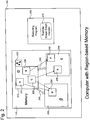
- Figure 2 illustrates a block diagram showing an exemplary computer 130 utilizing region-based memory 140.
- the memory comprises three regions 210 each containing various objects 230.
- objects contained in a region-based memory-system may contain references to other objects, as illustrated by the thin arrows connecting the objects 230.
- object C in region ⁇ in Figure 2 contains both a reference to object D in region ⁇ and a reference to object E in region ⁇ .
- object A also contains a reference to object D and object B contains a references to object F.
- these references comprise fields contained in objects A , B , and C .
- references to objects may also be maintained within local method or function variables.
- the term "field" as used herein will refer generally to any object reference, including global and local variables, not solely to fields described in object classes.
- Figure 2 also shows associations between regions 210, illustrated by the thick arrows 240.
- these associations represent the existence of references between objects contained within the regions.
- these associations are not actually maintained as separate entities within the computer 130, but rather are kept in one or more shape graphs, which are maintained along with regions to allow the computer 130 to locate objects and create region associations.
- a shape graph 250 is maintained along with region ⁇ which shows that region ⁇ has objects which are contained in the other two illustrated regions. While the illustrated example demonstrates maintaining one shape graph 250 in association with region ⁇ , in alternate implementations a plurality of shape graphs may be maintained. While in the illustrated example the region 250 is maintained along with region a, in another implementation shape graphs are maintained separately from the memory regions 210. Alternatively, a global shape graph may be kept which describes associations between all possible regions.
- the shape graph 250 contains metadata which maintains associations between regions based on object references by containing nodes representing regions and directed edges between the nodes which demonstrate associations between regions.
- the shape graph edges represent reference names.
- the shape graph 250 could contain information that any object referenced by a field called "age" in an object in region ⁇ will be contained in region ⁇ by containing ⁇ and P nodes connected by a "age" edge.
- shape graphs may associate regions by different or additional information, such as object type, level of protection of the reference, or by utilizing unique field identifiers.
- shape graphs are maintained as data structures describing nodes and edges. In alternate implementations, different data structures may be used, as long as the structures comprise metadata which maintains associations between regions.
- regions are allocated and associated with each other based on information in the shape graph 170 during the execution of the program. This is performed by using shape graphs as a templates for runtime region creation and association. In one implementation, regions are created during execution when they are first used. In another, when one region is created, if that region is described in a reachable subset of the shape graph then all other regions represented in the subset are created as well.
- Figure 2 also illustrates a runtime shape graph handler module 270, running within the executing program 260, which can analyze the shape graph 250 to determine the region associations, allocate objects properly, and provide for region allocation and de-allocation. For instance, if at a particular point in the execution of a program on computer 130 the object D was not yet created, the shape graph handler module 270 would be able to create the memory region ⁇ and allocate the object D within it at the time the object was to be created.
- the shape graph handler 270 comprises a discrete module within the executing program 260.
- a separate runtime environment does not exist, and the functions of the shape graph handler are included in the compiled program 160 at compilation.
- the shape graph handler is incorporated into the runtime environment in which the executing program runs.
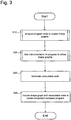
- Figure 3 illustrates, in one embodiment, a process for creating a program using region-based memory management employing shape graphs.
- the process represented in Figure 3 may be modified; blocks may be performed in a different order, may be combined, or may be broken into sub-blocks.
- the process starts at block 310, where the program code 150 is analyzed to create one or more shape graphs 170.
- the process of shape graph creation is described in more detail with respect to Figures 4 , 5 , and 6 .
- the process of Figure 3 continues to block 320 where instrumentation is added to the object-oriented program code 150 by the memory management code generator 120 to allow the computer 130 to utilize the shape graphs at runtime.
- executable code is generated from the modified object-oriented program code 150.
- the shape graph 170 created in the process of block 310 is included with the executable code 165 generated in the process of block 330 to create the completed compiled program 160.
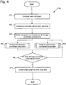
- Figure 4 illustrates one example of the process of block 310 of Figure 3 performed by the shape graph generator 110 for creating shape graphs.
- the process represented in Figure 4 may be modified; blocks may be performed in a different order, may be combined, or may be broken into sub-blocks.
- the process of Figure 4 is a modified version of the context sensitive points-to analysis for locating synchronizations by Erik Ruf in "Effective Synchronization Removal for Java," (2000) (“Ruf"), which is hereby incorporated by reference.
- Alternate implementations may employ different shape graph creation processes which are context sensitive or context-insensitive.
- the process starts at block 410, where the program is analyzed to compute a static call graph, which indicates, for every method, which methods are called by that method. Subsequent blocks are concerned with the creation and manipulation of alias sets, from which shape graph nodes and edges are created.
- An alias set as described in Ruf, is a data structure used to represent a set of object references, along with mappings from field names to other alias sets. In one implementation, the field names come from fields of the objects represented by the alias set when they are used in the program code 150.
- alias sets support unification operations, detailed by Ruf, which combine existing alias sets. Unification operations are performed according to statements contained in the program code 150.
- the process of Figure 4 will utilize alias set creation and unification to result in alias sets which together represent object references in the program.
- the process of Figure 4 will have created alias sets which together represent every object reference in the program.
- shape graphs are created. In different implementations the shape graph may be maintained in various data structures, as long as the directed graph nature of the shape graph is maintained.
- an alias set comprises only a field map and an indication of whether one of the object references the alias set refers to can be reached from a global variable.
- the alias set for a reference to an object which has fields "name” and "age” could comprise ⁇ name ⁇ 1, , age ⁇ 2 >,no >, where ⁇ 1 and ⁇ 2 are other alias sets representing the references made by the object's "name” and “age” fields, respectively, and the "no" indicates that the variable cannot be reached from a static global variable.
- the reachability information may be discarded before final creation of shape graph.
- an alias set is computed for each object reference in the object-oriented program code. Because alias sets as described by Ruf are initially created with empty field maps, the alias sets created for each field in block 420 will be created empty.
- the process continues to block 430 where the static call graph created in block 410 is divided into a set of strongly-connected components, which are to be analyzed individually. This process allows the shape graph generator module 110 to analyze the program code 150 in smaller segments and to ignore methods and fields which are not referenced within a strongly-connected component, increasing the efficiency of the analysis. In another implementation, the call graph is not divided into strongly-connected components. Additionally, at block 430 the strongly-connected components are placed in order. In the preferred implementation this is done in bottom-up topological order although in other implementations other orderings may be utilized.
- the first strongly-connected component is analyzed to create and unify alias sets based on statements in the program code 150.
- This analysis process is described in greater detail below with respect to Figures 5 and 6 .
- the process continues to decision block 460, where the shape graph generator 110 determines if there is an additional strongly-connected component. If so, the process continues to block 450, where the next strongly-connected component is analyzed and the process is repeated. If not, the process continues to block 470, where the alias sets, which have been modified and enriched by the analysis of blocks 440 and 450 are converted into shape graphs. In one implementation, information contained in the alias sets about global rechability is discarded before creation of shape graphs. The process then ends.
- Figure 5 illustrates one example of the process of blocks 440 and 450 of Figure 4 performed by the shape graph generator 110 of compiler 100 for analyzing the strongly-connected components ("SCCs") of the program code 150 to create shape graphs.
- SCCs strongly-connected components
- the process represented in Figure 5 may be modified; blocks may be performed in a different order, may be combined, or may be broken into sub-blocks.
- the process starts at block 505, where an initial method context is created for each method in the strongly-connected component being analyzed.
- a method context is a tuple of the form ⁇ f 0 ,..., f n >, r, e > where each of the f i 's, r, and e, are alias sets corresponding to the formal values received by the caller of the method, the return value, and the exception value for that method. In alternate implementations more than one exception value may be used, or none at all may be used.
- Method contexts are created in order to allow alias sets created in called methods to be systematically reflected by alias sets created for the context where the method is called, making a more complete and context-sensitive shape graph template analysis. Next, each method in the SCC is analyzed in turn.
- each parameter variable in the first analyzed method is associated with its corresponding alias set from the method context.
- the process then analyzes the first statement at block 515 to determine the process that is performed in the statement. As Ruf describes, if the statement modifies references variables, processes a value, or calls a method, alias sets may need to be unified.
- the shape graph template generator 110 determines whether the statement analyzed is a method call. If it is, the process continues to block 525, where unification of alias sets is performed according to particular method call rules. The process of unifying alias sets over method calls is described in greater detail below with respect to the process of Figure 6 .
- alias sets are unified according to alias set analysis rules.
- v 0 v 1.
- f a field name
- the rule causes the alias set associated with v 0 and the alias set mapped to by f in the alias set for v 1 to be unified.
- the practical effect of this unification is to cause references to v 0 to lead to the same alias set as references from the f field of v 1 .
- objects that are referred to by the v 0 variable and by the f field of v 1 will be allocated in the same region.
- An example list of analysis rules can be found in Ruf.
- the process then continues to decision block 540, where the shape graph generator determines whether other statements exist in the currently-analyzed method. If other statements do exist, the process continues to block 550 where the next statement in the method is analyzed. If there are no more statements in the method, the process continues to decision block 545 where the shape graph generator determines if other methods exist in the SCC. If so, the process continues to block 555 where parameter variables in the next method are associated with alias sets from that method's method context. If, however, there are no more methods in the SCC, the process of Figure 5 ends.
- Figure 6 illustrates one example of the process of block 525 of Figure 5 performed by the shape graph generator 110 of compiler 100 for performing alias set unification or instantiation due to a method call.
- method calls which undergo the process represented in Figure 6 include not only specially-defined class methods but also constructors and destructor methods.
- the process represented in Figure 6 may be modified; blocks may be performed in a different order, may be combined, or may be broken into sub-blocks.
- the process begins at block 610, where a site context is created for the method call.
- a site context takes the same ⁇ f 0 ,..., f n >, r, e> form as a method context, but instead of representing values received from a caller or returned to a caller, the f i 's represent actual values transmitted to the callee, and r and e represent values returned by the callee.
- the shape graph generator 110 determines whether the method call is recursive. If the call is not recursive, the process continues to block 630, where a new instance of the method context for the called method is created.
- the creation of a new method context creates a method context with alias sets that are isomorphic to the original ones.
- the isomorphic alias sets used in the new instance are newly-created instances of alias sets, unless the alias set being copied from is available from a global variable, in which case the original alias set is used in the new method context instance.
- the site context is unified with the new instance of the method context by unifying each alias set of the site context with its corresponding alias set in the new method context.
- the creation of a new instance of the method context allows a context-sensitive analysis. After this unification, the process then ends.
- the effects of the processes described by blocks 630 and 640 are achieved by an instantiation process using polymorphic type inference similar to the kind described in Steensgaard.
- the call site context is unified with the existing method context for the called method without creating a new method context. While in one implementation the different treatment of recursive method calls creates context insensitivity, it prevents the performance costs of having to iterate over the entire SCC until a fixed point is reached for the recursive call. After this unification, the process then ends. In an alternative implementation, the effects of the process described by block 650 are achieved by an instantiation process using polymorphic type inference similar to the kind described in Steensgaard.
- Figures 7a and 7b illustrate two examples of objects stored in regions according to a common shape graph.
- the shape graph is not shown as a separate entity, but is illustrated through the illustrated edges connecting regions.
- the shape graph from which both examples are derived is created from an analysis of the following code:
- the two examples show differences in the type and number of objects located in the regions which depend on the execution of the program.
- the two possible executions of the example code are parameterized by argument length.
- An analysis of the code creates a shape graph which comprises a template for the creation of five memory regions, as Figures 7a and 7b illustrate.
- the first memory region, region 700 will always, after execution, contain a Table object referred to by the local field "table.”
- the second, region 710 will always contain a Pair object referred to by the "One" field of the Table of region 700.
- Region 720 may contain different types of objects.
- the shape graph describes region 720 as containing a objects referred to by the "two" field of objects of region 700.
- Figure 7a, and Figure 7b illustrate, in one execution of the code a Pair object is allocated in region 720 and in another execution of the code a Triple object is located in region 720. This is done because Triple is a subclass of Pair and either the Pair of Figure 7a or the Triple of Figure 7b ends up referred to by the "two" field of the object in region 700.
- Figures 7a and 7b illustrate, a region can contain objects of different classes.
- Figures 7a and 7b also demonstrate that, in one implementation, the analysis does not incorporate differences between public and private fields into the shape graph.
- the "One" field is a public field and the "two" field is private, but because both refer to objects, both are included in the shape graph.
- the shape graph from which both Figures 7a and 7b are formed describes region 730 as containing objects referred to by the "left" field of the objects of region 720 and describes region 740 as containing objects referred to by the "right” field of objects in region 720.
- Region 740 has different contents depending on the execution of the program.
- Figure 7a which illustrates the program execution where the length of the program arguments is greater than 1
- the "two" field refers to a Pair object, which has only "left” and “right” fields.
- the "two" field refers to a Triple object, which contains not only the “left” and “right” fields of a Pair, but additionally contains a "middle” field.
- region 740 contains the two objects referred to by the "middle” and "right” fields.
- the shape graph describes the referents of both the "middle” and “right” fields as being in the same region rather than putting them in separate regions. In one implementation, this is a direct result of the use of alias sets as described by Ruf for shape graph creation.
- the reason for this in the example of Figures 7a and 7b is the existence of the "shared" reference in the main method. Under the two possible executions of the program, "shared” may be assigned to either the "right” field of a Pair object in region 720 or the "middle” field of a Triple object in region 720. As a consequence of the assignment to the "right” field, objects referenced by the "shared” and “right” fields must be in the same region.
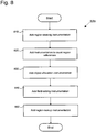
- Figure 8 describes one implementation of the process performed in block 320 by the memory management code generator 120 for adding instrumentation to utilize shape graphs.
- the process represented in Figure 3 may be modified; blocks may be performed in a different order, may be combined, or may be broken into sub-blocks.
- the instrumentation added by the processes of Figure 8 in one implementation may be added as source code, such as method calls or inlined code, prior to compilation. Alternately, the instrumentation is added to code on which compilation has begun or is completed, such as in the form of bytecode or machine code. Additionally, the inclusion of some instrumentation may involve the manipulation or transformation of existing program code rather than only the addition of new code. While one implementation consolidates region and shape graph handling routines into the shape graph handler 270 of the executing program 260, in other implementations the routines are generally incorporated into the code of the object-oriented program.
- the process beings at block 810, where region-creating instrumentation is added.
- the instrumentation accepts a global shape graph and allocates a region based on an indication of which region from the shape graph is needed.
- only the section of the shape graph necessary to describe the region is given to the region-creating instrumentation.
- different implementations may create regions at different times during execution. In one implementation, all regions corresponding to a reachable subset of a shape graph are created at the same time. In another, regions are created as-needed by the program.
- Region-creation instrumentation may also, in one implementation, include instrumentation for the simultaneous creation of sets of regions which are strongly-connected in the shape graph. This is useful because, in one implementation, reference counters are used to keep track of which regions are still being used in during the execution of the program. If separate counters were kept for each region in a strongly-connected set a condition could develop during program execution where no references exist from any regions outside the set, yet because of the strongly-connected nature of the set, references could still exist inside. Thus, the reference counter for the regions might never reach zero, even though, relative to the rest of the program, the set is "dead" and cannot be referenced again by any object outside the set. This would keep the regions artificially alive, rather than being de-allocated and having their memory returned to the system.
- the shape graph is determined to describe a set of strongly-connected regions, instrumentation is added creating all the regions at once rather than separately.
- strongly-connected region sets are not created simultaneously, although in order to avoid the problem described above different instrumentation with regard to reference counters is useful.
- strongly connected components in the points-to graph are reduced to single nodes in the shape graph, which ensures that the shape graph is a directed acyclic graph.
- the process then continues to block 820, where instrumentation is added allowing the program to count region references.
- this involves the creation of reference count variables for every region.
- the reference count variables for strongly-connected region sets are combined into a single count which counts only references from regions outside the strongly-connected set.
- the use of a single count for strongly-connected region sets prevents the problem mentioned above by ignoring references among regions inside the set.
- a single count may be kept for each subset of a strongly-connected set that is strongly-connected at each point during execution. When subsets of the larger strongly-connected set are linked by a reference during runtime, the counts can then be merged into a single count.
- the memory-management code generator 120 also adds instrumentation to increment and decrement reference counts.
- code is added before references are created to add to the reference count for the region for which the reference is created. Thus, every time a reference to an object is created, the reference count for that object's region is increased by one.
- the decrementing instrumentation a last-use analysis is performed on the code during compile-time by the memory-management code generator 120 to determine when the reference counts may be decremented.
- the instrumentation for decrementing reference counters additionally includes instrumentation to de-allocate regions and the objects contained in them. Additionally, in implementations described above, the addition of a reference to an object in a region from a strongly-connected set of regions may cause a single count for the entire set to increment, or may cause the merger of counts.
- object allocation instrumentation is added to the program.
- this instrumentation comprises an object allocation routine or method which takes an indication of a region and the type or size of an object and allocates the object within the region.
- this instrumentation comprises a routine or method which takes an indication of two existing regions and a field and populates the template provided by the shape graph by setting the edge corresponding to the field to the second region. This allows regions which are created lazily during the course of execution to be associated with already-existing regions when the program deems necessary. This can be done both for setting fields that refer to a new object and for setting fields in a new object to refer to objects in older regions.
- instrumentation is added which allows regions to be looked up. This can be done in multiple ways.
- a lookup routine or method is used which, given an indication of a region and a field used by an object in that region, finds the region containing the object referred-to by the given field.
- instrumentation is added to allow regions to be found in particular circumstances so that the field-setting routine described above with respect to block 840 may be used. In particular this is done for methods which take an input object and create a new object in a region reachable from the region containing the input object The situation exists when the region containing the new object is only indirectly reachable from the region containing the input object.
- instrumentation is added which allows the program at runtime to identify the region containing the input object from the shape graph and traverse the shape graph to find the region of the new object while creating regions and region edges as necessary to establish a path or a plurality of paths from the region containing the input object to the region containing the new object.
- This instrumentation is not limited to this particular example; other situations may arise depending on the structure of the program code which require addition of instrumentation to traverse shape graphs and resolve references to regions which are not directly available.
- instrumentation is added so that regions can be found during method execution.
- this comprises a different lookup routine which, given an object will provide the region in which that object is contained.
- This implementation would allow the program to execute with a reduced set of shape graphs available, because regions could be directly found from the objects inside them.
- objects could be passed into methods with no additional parameters.
- this implementation may provide additional overhead because of the necessity of keeping many object-region associations in runtime memory.
- another implementation uses shape graphs to find the regions containing objects when those objects are passed into methods. This is done by adding instrumentation so that when an object is passed to a method, the region for the object is found using the shape graph, and passed to the method as well, allowing the region to be maintained properly during method execution. This is similar to the techniques described by Christiansen and Velschow, where many regions where passed with each object. But because in the techniques described herein at most one region is passed per object passed, the overhead implicit in Christiansen and Velschow's techniques is sharply reduced. Additionally, the passing of only the regions that contain a method's input objects prevents out-of-context region information from being incorporated into methods, allowing a programmer studying the method to examine it without reference to the method calling it or methods that it calls.
- regions containing argument objects area always passed along with the argument objects when doing a method call.
- regions are only passed to methods that analysis of the object-oriented code identified as potentially allocating objects in the argument objects' regions or in regions reachable from the argument objects' regions.
- regions are also passed to methods that analysis identifies as potentially deallocating one or more argument regions or one or more regions reachable from the argument objects' regions.
- a globally-maintained shape graph is considered for all method calls.
- sub-graphs of the global shape graph are associated with regions, as illustrated in Figure 2 , so that only the necessary parts of the shape graph are consulted before a method call.
- the above described compiler 100 and executing computer 130 can be implemented on any of a variety of computing devices and environments, including computers of various form factors (personal, workstation, server, handheld, laptop, tablet, or other mobile), distributed computing networks, and Web services, as a few general examples.
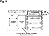
- the compiler 100 and runtime environment 260 can be implemented in hardware circuitry, as well as in compiling or runtime software executing within a computer or other computing environment, such as shown in Figure 9 .
- FIG. 9 illustrates a generalized example of a suitable computing environment 900 in which the described techniques can be implemented.
- the computing environment 900 is not intended to suggest any limitation as to scope of use or functionality of the invention, as the present invention may be implemented in diverse general-purpose or special-purpose computing environments.
- the computing environment 900 includes at least one processing unit 910 and memory 920.
- the processing unit 910 executes computer-executable instructions and may be a real or a virtual processor. In a multi-processing system, multiple processing units execute computer-executable instructions to increase processing power.
- the memory 920 may be volatile memory (e.g., registers, cache, RAM), nonvolatile memory (e.g., ROM, EEPROM, flash memory, etc.), or some combination of the two. In one implementation, the memory 920 stores software 980 implementing the compiler 100 or the runtime environment 260.
- a computing environment may have additional features.
- the computing environment 900 includes storage 940, one or more input devices 950, one or more output devices 960, and one or more communication connections 970.
- An interconnection mechanism such as a bus, controller, or network interconnects the components of the computing environment 900.
- operating system software provides an operating environment for other software executing in the computing environment 900, and coordinates activities of the components of the computing environment 900.
- the storage 940 may be removable or non-removable, and includes magnetic disks, magnetic tapes or cassettes, CD-ROMs, CD-RWs, DVDs, or any other medium which can be used to store information and which can be accessed within the computing environment 900.
- the storage 940 stores instructions for the compiling and runtime software.
- the input device(s) 950 may be a touch input device such as a keyboard, mouse, pen, or trackball, a voice input device, a scanning device, or another device that provides input to the computing environment 900.
- the input device(s) 950 may be a sound card or similar device that accepts audio input in analog or digital form, or a CD-ROM reader that provides audio samples to the computing environment.
- the output device(s) 960 may be a display, printer, speaker, CD-writer, or another device that provides output from the computing environment 900.
- the communication connection(s) 970 enable communication over a communication medium to another computing entity.
- the communication medium conveys information such as computer-executable instructions, audio/video or other media information, or other data in a modulated data signal.
- a modulated data signal is a signal that has one or more of its characteristics set or changed in such a manner as to encode information in the signal.
- communication media include wired or wireless techniques implemented with an electrical, optical, RF, infrared, acoustic, or other carrier.
- Computer-readable media are any available media that can be accessed within a computing environment.
- Computer-readable media include memory 920, storage 940, communication media, and combinations of any of the above.
- program modules include routines, programs, libraries, objects, classes, components, data structures, etc. that perform particular tasks or implement particular abstract data types.
- the functionality of the program modules may be combined or split between program modules as desired in various embodiments.
- Computer-executable instructions for program modules may be executed within a local or distributed computing environment.
Landscapes
- Engineering & Computer Science (AREA)
- Theoretical Computer Science (AREA)
- Physics & Mathematics (AREA)
- General Engineering & Computer Science (AREA)
- General Physics & Mathematics (AREA)
- Devices For Executing Special Programs (AREA)
- Memory System (AREA)
- Information Retrieval, Db Structures And Fs Structures Therefor (AREA)
- Stored Programmes (AREA)
Claims (15)
- Verfahren zum Kompilieren eines objektorientierten Programms, wobei das Programm dazu konfiguriert ist, in einem System ausgeführt zu werden, das eine bereichsbasierte Speicherverwaltung nutzt, und wobei das Verfahren umfasst:Empfangen eines Quellcodes für ein objektorientiertes Programm;Durchführen (310) einer Verweist-auf-Analyse an dem Quellcode, um mindestens eine Datenstruktur zu entwickeln, die Bereichszuordnungsmetadaten für das Programm enthält, wobei Zuordnungen zwischen Bereichen die Existenz von Verweisen zwischen Objekten repräsentieren, die in den Bereichen enthalten sind;Hinzufügen (320) von Instrumentation zu dem Programm, wobei die Instrumentation dazu konfiguriert ist:die Erzeugung von Objekten in Bereichen basierend auf Informationen in der Datenstruktur zu veranlassen; unddas Löschen aller Objekte in einem Bereich zu veranlassen, wenn die Bestimmung getroffen wird, dass keine Verweise auf Objekte in dem Bereich von Feldern außerhalb des Bereichs bestehen; undKompilieren des Programms, wobei die Datenstruktur in dem kompilierten Programm enthalten ist.
- Verfahren nach Anspruch 1, wobei die Datenstruktur, welche Bereichszuordnungsmetadaten enthält, ein Formdiagramm umfasst.
- Verfahren nach Anspruch 2, wobei:das mindestens ein Bereichsformdiagramm eine Vielzahl von Knoten umfasst, die durch Programmränder verbunden sind;jeder Knoten einen Bereich in einem Speicher repräsentiert; undjeder Rand einen oder mehrere Verweise zwischen den Objekten eines Bereichs und den Objekten eines anderen Bereichs repräsentiert.
- Verfahren nach Anspruch 2, wobei jeder Bereich ein ihm zugeordnetes Formdiagramm aufweist und jedes Formdiagramm zusammen mit den ihm zugeordneten Bereichen gespeichert wird.
- Verfahren nach Anspruch 2, wobei mindestens ein Formdiagramm weniger als die Gesamtanzahl der Bereiche repräsentiert.
- Verfahren nach Anspruch 2, wobei das Durchführen einer Verweist-auf-Analyse umfasst:Erzeugen (420) von Alias-Sätzen für Parameter, basierend auf Anweisungen, die in den Verfahren des objektorientierten Programms enthalten sind;Zusammenführen (440) der Alias-Sätze, basierend auf Anweisungen, die in den Verfahren des Programms enthalten sind;Erzeugen (470) von mindestens einem Formdiagramm mit Knoten, die von den Alias-Sätzen definiert werden, und Rändern, die durch Feldzuordnungen zwischen Alias-Sätzen definiert sind; undZuordnen der Knoten des Formdiagramms zu potentiellen Speicherbereichen.
- Verfahren nach Anspruch 2, wobei die hinzugefügte Instrumentation zumindest teilweise umfasst:einen Bereichserzeugungscode, der einen Bereich unter Vorgabe eines Formdiagramms erzeugt;einen Objektzuordnungscode, der unter Vorgabe von Bereichs- und Objektinformationen ein Objekt in einem bestimmten Bereich zuordnet; undeinen Bereichs-Lookupcode, der unter Vorgabe eines Bereichs und eines Identifikators eines Feldes den Bereich identifiziert, auf den das Feld verweist.
- Verfahren nach Anspruch 7, wobei die hinzugefügte Instrumentation des Weiteren einen Feld-Einstellungscode umfasst, der unter Vorgabe von zwei Bereichen und einem Verweis auf ein Feld von einem Objekt in einem Bereich, der auf ein Objekt in dem anderen Bereich verweist, das Formdiagramm so einstellt, dass es die Knoten entsprechend den zwei Bereichen durch einen Rand verbindet, der dem Feld entspricht.
- Verfahren nach Anspruch 7, wobei das Nutzen einer bereichsbasierten Speicherverwaltung zumindest zum Teil umfasst:Pflegen eines Zählers für jeden Bereich oder jeden Bereichssatz der Anzahl der Verweise auf die Objekte, die in diesem Bereich oder Satz enthalten sind; undbei Bestimmen, dass der Zähler für einen Bereich oder Bereich Satz null ist, Löschen des Bereichs oder Satzes; undwobei die hinzugefügte Instrumentation des Weiteren umfasst:einen Erhöhungscode, der unter Vorgabe eines Bereichs oder Bereichssatzes den Zähler erhöht, der für diesen Bereich oder Satz gepflegt wird; undeinen Verringerungscode, der unter Vorgabe eines Bereichs oder Bereichssatzes den Zähler verringert, der für diesen Bereich oder Satz gepflegt wird.
- Verfahren nach Anspruch 1, wobei das Bestimmen, dass kein Verweis auf Objekte vorhanden ist, umfasst:Pflegen eines Zählers für jeden Bereich der Anzahl der Verweise auf Objekte, die in dem Bereich enthalten sind; undbei Bestimmen, dass der Zähler für einen Bereich null ist, Bestimmen, dass keine Objekte in dem Bereich enthalten sind, auf die Verweise von anderen Feldern bestehen.
- Verfahren nach Anspruch 1, des Weiteren umfassend einen Speicherbereiniger.
- Verfahren nach Anspruch 1, wobei nicht mehr als ein Bereichsparameter an ein Verfahren für jedes Objekt weitergegeben wird, das an ein Verfahren weitergegeben wird.
- Computerlesbares Medium mit Befehlen, die bei Ausführung einen Computer dazu veranlassen, das Verfahren nach einem der Ansprüche 1 bis 12 durchzuführen.
- Compilersystem (100), das dazu eingerichtet ist, einen objektorientierten Programmcode (150) zur Kompilierung zu einem kompilierten Programm (160) zu empfangen, wobei das System umfasst:einen Formgrafikgenerator (110), der dazu eingerichtet ist, den objektorientierten Programmcode zu analysieren, um mindestens ein Formdiagramm (170) zu erstellen, das Bereichszuordnungsmetadaten für das kompilierte Programm enthält, wobei Zuordnungen zwischen Bereichen die Existenz von Verweisen zwischen Objekten repräsentieren, die in den Bereichen enthalten sind; undeinen Speicherverwaltungs-Codegenerator (120), der dazu eingerichtet ist, zusätzliche Instrumentation in ausführbaren Code (185) des kompilierten Programms einzusetzen,wobei die zusätzliche Instrumentation dazu konfiguriert ist:die Erzeugung von Objekten in Bereichen basierend auf Informationen in dem Formdiagramm zu veranlassen; unddas Löschen aller Objekte in einem Bereich zu veranlassen, wenn die Bestimmung getroffen wird, dass keine Verweise auf Objekte in dem Bereich von Feldern außerhalb des Bereichs bestehen, undwobei das Formdiagramm in dem kompilierten Programm enthalten ist.
- Compilersystem nach Anspruch 14, des Weiteren umfassend Mittel, die zum Durchführen des Verfahrens nach einem der Ansprüche 1 bis 12 eingerichtet sind.
Applications Claiming Priority (4)
| Application Number | Priority Date | Filing Date | Title |
|---|---|---|---|
| US783124 | 1991-10-28 | ||
| US50520503P | 2003-09-23 | 2003-09-23 | |
| US505205P | 2003-09-23 | ||
| US10/783,124 US7263532B2 (en) | 2003-09-23 | 2004-02-19 | Region-based memory management for object-oriented programs |
Publications (3)
| Publication Number | Publication Date |
|---|---|
| EP1519273A2 EP1519273A2 (de) | 2005-03-30 |
| EP1519273A3 EP1519273A3 (de) | 2009-01-07 |
| EP1519273B1 true EP1519273B1 (de) | 2016-12-28 |
Family
ID=34198314
Family Applications (1)
| Application Number | Title | Priority Date | Filing Date |
|---|---|---|---|
| EP04022556.7A Expired - Lifetime EP1519273B1 (de) | 2003-09-23 | 2004-09-22 | Bereichsbasierte Speicherverwaltung für objektorientierte Programme |
Country Status (5)
| Country | Link |
|---|---|
| US (2) | US7263532B2 (de) |
| EP (1) | EP1519273B1 (de) |
| JP (1) | JP4896384B2 (de) |
| KR (1) | KR20050030139A (de) |
| CN (1) | CN100474251C (de) |
Families Citing this family (32)
| Publication number | Priority date | Publication date | Assignee | Title |
|---|---|---|---|---|
| JP5689361B2 (ja) | 2011-05-20 | 2015-03-25 | インターナショナル・ビジネス・マシーンズ・コーポレーションInternational Business Machines Corporation | グラフデータの一部を準同型写像の像であるデータ構造に変換する方法、プログラム、および、システム |
| US20050283771A1 (en) * | 2004-06-22 | 2005-12-22 | Nokia Corporation | System and method for decreasing the memory footprint of applications with automatic memory management systems |
| US8204931B2 (en) | 2004-12-28 | 2012-06-19 | Sap Ag | Session management within a multi-tiered enterprise network |
| WO2006111010A1 (en) * | 2005-04-18 | 2006-10-26 | Research In Motion Limited | Centralized memory management in wireless terminal devices |
| US8589562B2 (en) | 2005-04-29 | 2013-11-19 | Sap Ag | Flexible failover configuration |
| CN100461176C (zh) * | 2006-01-26 | 2009-02-11 | 无锡永中科技有限公司 | 基于对象存储库的对象引用方法 |
| US20080163063A1 (en) * | 2006-12-29 | 2008-07-03 | Sap Ag | Graphical user interface system and method for presenting information related to session and cache objects |
| US9311082B2 (en) * | 2006-12-29 | 2016-04-12 | Sap Se | System and method for processing graph objects |
| US8640086B2 (en) * | 2006-12-29 | 2014-01-28 | Sap Ag | Graphical user interface system and method for presenting objects |
| US8332939B2 (en) * | 2007-02-21 | 2012-12-11 | International Business Machines Corporation | System and method for the automatic identification of subject-executed code and subject-granted access rights |
| US8230477B2 (en) * | 2007-02-21 | 2012-07-24 | International Business Machines Corporation | System and method for the automatic evaluation of existing security policies and automatic creation of new security policies |
| US20080307174A1 (en) * | 2007-06-08 | 2008-12-11 | Apple Inc. | Dual Use Memory Management Library |
| JP5403362B2 (ja) * | 2007-08-02 | 2014-01-29 | 日本電気株式会社 | パターン検査システム、パターン検査装置、方法およびパターン検査用プログラム |
| US8650228B2 (en) * | 2008-04-14 | 2014-02-11 | Roderick B. Wideman | Methods and systems for space management in data de-duplication |
| US8341602B2 (en) * | 2009-01-29 | 2012-12-25 | Microsoft Corporation | Automated verification of a type-safe operating system |
| US8776032B2 (en) * | 2009-01-29 | 2014-07-08 | Microsoft Corporation | Automatic region-based verification of garbage collectors |
| US8549490B2 (en) | 2009-09-29 | 2013-10-01 | International Business Machines Corporation | Static code analysis for packaged application customization |
| JP5185242B2 (ja) * | 2009-12-04 | 2013-04-17 | 株式会社東芝 | コンパイル装置 |
| US8239404B2 (en) * | 2010-06-10 | 2012-08-07 | Microsoft Corporation | Identifying entries and exits of strongly connected components |
| CN102722432B (zh) * | 2011-03-29 | 2016-02-24 | 国际商业机器公司 | 追踪内存访问的方法和装置 |
| JP5745932B2 (ja) | 2011-05-20 | 2015-07-08 | インターナショナル・ビジネス・マシーンズ・コーポレーションInternational Business Machines Corporation | グラフデータに写像の像であるオブジェクトに対する操作を反映する方法、プログラム、および、システム |
| US8966635B2 (en) * | 2012-02-24 | 2015-02-24 | Hewlett-Packard Development Company, L.P. | Software module object analysis |
| US10754766B2 (en) | 2014-03-21 | 2020-08-25 | Red Hat Israel, Ltd. | Indirect resource management |
| US9552274B2 (en) * | 2014-06-27 | 2017-01-24 | Vmware, Inc. | Enhancements to logging of a computer program |
| US9292281B2 (en) * | 2014-06-27 | 2016-03-22 | Vmware, Inc. | Identifying code that exhibits ideal logging behavior |
| US9405659B2 (en) | 2014-06-27 | 2016-08-02 | Vmware, Inc. | Measuring the logging quality of a computer program |
| CN106796513B (zh) * | 2014-07-18 | 2020-12-11 | 起元科技有限公司 | 管理沿袭信息 |
| WO2016195699A1 (en) * | 2015-06-05 | 2016-12-08 | Hexagon Technology Center Gmbh | Method and apparatus for performing a geometric transformation on objects in an object-oriented environment using a multiple-transaction technique |
| US9880743B1 (en) * | 2016-03-31 | 2018-01-30 | EMC IP Holding Company LLC | Tracking compressed fragments for efficient free space management |
| FR3070775B1 (fr) * | 2017-09-04 | 2019-08-23 | Vsora | Allocation dynamique utilisant plusieurs piles |
| CN108459552B (zh) * | 2018-01-31 | 2021-07-23 | 南京拓控信息科技股份有限公司 | 一种智能化面向对象的可编程的自动化控制方法 |
| US11416392B2 (en) * | 2019-06-20 | 2022-08-16 | Microsoft Technology Licensing, Llc | Arena-based memory management |
Family Cites Families (23)
| Publication number | Priority date | Publication date | Assignee | Title |
|---|---|---|---|---|
| US155764A (en) * | 1874-10-06 | Improvement in lifting-jacks | ||
| US126560A (en) * | 1872-05-07 | Improvement in churns | ||
| US30575A (en) * | 1860-11-06 | Improvement in apparatus for trying oils | ||
| US4989132A (en) * | 1988-10-24 | 1991-01-29 | Eastman Kodak Company | Object-oriented, logic, and database programming tool with garbage collection |
| JPH0728691A (ja) * | 1993-07-09 | 1995-01-31 | Nec Corp | ガーベージコレクション効率化方法 |
| US5687368A (en) * | 1994-07-22 | 1997-11-11 | Iowa State University Research Foundation, Inc. | CPU-controlled garbage-collecting memory module |
| US6009410A (en) * | 1997-10-16 | 1999-12-28 | At&T Corporation | Method and system for presenting customized advertising to a user on the world wide web |
| US6175957B1 (en) * | 1997-12-09 | 2001-01-16 | International Business Machines Corporation | Method of, system for, and computer program product for providing efficient utilization of memory hierarchy through code restructuring |
| JP3385957B2 (ja) | 1998-03-04 | 2003-03-10 | 日本電気株式会社 | 分散システム、メモリ管理装置及び方法、並びに記録媒体 |
| US6006197A (en) * | 1998-04-20 | 1999-12-21 | Straightup Software, Inc. | System and method for assessing effectiveness of internet marketing campaign |
| BR9908574A (pt) * | 1999-01-06 | 2000-11-21 | Koninkl Philips Electronics Nv | Sistema e processo para executar código de programa, e, suporte tangìvel portador de um programa de computador para realizar o dito processo |
| US6941321B2 (en) * | 1999-01-26 | 2005-09-06 | Xerox Corporation | System and method for identifying similarities among objects in a collection |
| US6286001B1 (en) * | 1999-02-24 | 2001-09-04 | Doodlebug Online, Inc. | System and method for authorizing access to data on content servers in a distributed network |
| US6249793B1 (en) * | 1999-06-10 | 2001-06-19 | Sun Microsystems, Inc. | Mostly concurrent compaction in a garbage collection system |
| US6434576B1 (en) * | 1999-08-19 | 2002-08-13 | Sun Microsystems, Inc. | Popular-object handling in a train-algorithm-based garbage collector |
| US6964037B1 (en) * | 1999-09-19 | 2005-11-08 | Kestrel Institute | Method and apparatus for determining colimits of hereditary diagrams |
| US6594678B1 (en) * | 2000-01-05 | 2003-07-15 | Sun Microsystems, Inc. | Methods and apparatus for improving locality of reference through memory management |
| GB0007493D0 (en) * | 2000-03-28 | 2000-05-17 | Tao Group Ltd | Garbage collection |
| US6865657B1 (en) * | 2000-06-02 | 2005-03-08 | Sun Microsystems, Inc. | Garbage collector for a virtual heap |
| JP2002278828A (ja) * | 2001-03-21 | 2002-09-27 | Sony Corp | ガーベージコレクション実行方法、コンピュータプログラム、プログラム格納媒体、および情報処理装置 |
| JP4041347B2 (ja) * | 2001-05-29 | 2008-01-30 | 松下電器産業株式会社 | ガベージコレクション装置及びガベージコレクション方法 |
| US7036120B2 (en) * | 2001-07-31 | 2006-04-25 | Sun Microsystems, Inc. | Two tier clusters for representation of objects in Java programming environments |
| US20050234985A1 (en) * | 2004-04-09 | 2005-10-20 | Nexjenn Media, Inc. | System, method and computer program product for extracting metadata faster than real-time |
-
2004
- 2004-02-19 US US10/783,124 patent/US7263532B2/en not_active Expired - Fee Related
- 2004-09-22 EP EP04022556.7A patent/EP1519273B1/de not_active Expired - Lifetime
- 2004-09-22 JP JP2004275876A patent/JP4896384B2/ja not_active Expired - Fee Related
- 2004-09-23 CN CNB2004101023346A patent/CN100474251C/zh not_active Expired - Fee Related
- 2004-09-23 KR KR1020040076272A patent/KR20050030139A/ko not_active Withdrawn
-
2007
- 2007-08-22 US US11/843,532 patent/US20080010327A1/en not_active Abandoned
Non-Patent Citations (1)
| Title |
|---|
| None * |
Also Published As
| Publication number | Publication date |
|---|---|
| US7263532B2 (en) | 2007-08-28 |
| CN100474251C (zh) | 2009-04-01 |
| JP4896384B2 (ja) | 2012-03-14 |
| EP1519273A3 (de) | 2009-01-07 |
| JP2005100402A (ja) | 2005-04-14 |
| EP1519273A2 (de) | 2005-03-30 |
| US20080010327A1 (en) | 2008-01-10 |
| US20050065973A1 (en) | 2005-03-24 |
| KR20050030139A (ko) | 2005-03-29 |
| CN1661559A (zh) | 2005-08-31 |
Similar Documents
| Publication | Publication Date | Title |
|---|---|---|
| EP1519273B1 (de) | Bereichsbasierte Speicherverwaltung für objektorientierte Programme | |
| US6898611B1 (en) | Declarative pinning | |
| Choi et al. | Escape analysis for Java | |
| US6381738B1 (en) | Method for optimizing creation and destruction of objects in computer programs | |
| Agesen et al. | Garbage collection and local variable type-precision and liveness in Java virtual machines | |
| US6505344B1 (en) | Object oriented apparatus and method for allocating objects on an invocation stack | |
| US5907707A (en) | Object model for Java | |
| JP3110040B2 (ja) | 手順間レジスタ割付けを伴うコンピュータプログラムのコンパイル方法及び装置 | |
| US20020107996A1 (en) | Method and apparatus for dispatch table construction | |
| US20070226281A1 (en) | Reference-counting subsumption analysis | |
| Gheorghioiu et al. | Interprocedural compatibility analysis for static object preallocation | |
| Hosking et al. | Towards compile-time optimisations for persistence | |
| US20070198617A1 (en) | Eager reference-counting garbage collection | |
| US20090094301A1 (en) | Applications of overlooking root information for improving nondeferred reference-counting garbage collection | |
| Jones et al. | A fast analysis for thread-local garbage collection with dynamic class loading | |
| US8103706B2 (en) | Nondeferred reference-counting garbage collection using overlooking roots | |
| US11875193B2 (en) | Tracking frame states of call stack frames including colorless roots | |
| Krall et al. | Optimizations for Object-Oriented Languages | |
| US11513954B2 (en) | Consolidated and concurrent remapping and identification for colorless roots | |
| US11789863B2 (en) | On-the-fly remembered set data structure adaptation | |
| US11573794B2 (en) | Implementing state-based frame barriers to process colorless roots during concurrent execution | |
| Brahnmath | Optimizing orthogonal persistence for Java | |
| Jones et al. | Collecting the garbage without blocking the traffic | |
| Ungureanu et al. | Concurrency analysis for Java | |
| ァゥ et al. | Escape Analysis for Java |
Legal Events
| Date | Code | Title | Description |
|---|---|---|---|
| PUAI | Public reference made under article 153(3) epc to a published international application that has entered the european phase |
Free format text: ORIGINAL CODE: 0009012 |
|
| AK | Designated contracting states |
Kind code of ref document: A2 Designated state(s): AT BE BG CH CY CZ DE DK EE ES FI FR GB GR HU IE IT LI LU MC NL PL PT RO SE SI SK TR |
|
| AX | Request for extension of the european patent |
Extension state: AL HR LT LV MK |
|
| RIN1 | Information on inventor provided before grant (corrected) |
Inventor name: SPOONHOWER, DANIEL JOHN Inventor name: STEENSGAARD, BJARNE |
|
| 17P | Request for examination filed |
Effective date: 20070924 |
|
| PUAL | Search report despatched |
Free format text: ORIGINAL CODE: 0009013 |
|
| AK | Designated contracting states |
Kind code of ref document: A3 Designated state(s): AT BE BG CH CY CZ DE DK EE ES FI FR GB GR HU IE IT LI LU MC NL PL PT RO SE SI SK TR |
|
| AX | Request for extension of the european patent |
Extension state: AL HR LT LV MK |
|
| 17Q | First examination report despatched |
Effective date: 20090624 |
|
| AKX | Designation fees paid |
Designated state(s): AT BE BG CH CY CZ DE DK EE ES FI FR GB GR HU IE IT LI LU MC NL PL PT RO SE SI SK TR |
|
| RAP1 | Party data changed (applicant data changed or rights of an application transferred) |
Owner name: MICROSOFT TECHNOLOGY LICENSING, LLC |
|
| GRAP | Despatch of communication of intention to grant a patent |
Free format text: ORIGINAL CODE: EPIDOSNIGR1 |
|
| INTG | Intention to grant announced |
Effective date: 20160718 |
|
| GRAS | Grant fee paid |
Free format text: ORIGINAL CODE: EPIDOSNIGR3 |
|
| GRAA | (expected) grant |
Free format text: ORIGINAL CODE: 0009210 |
|
| AK | Designated contracting states |
Kind code of ref document: B1 Designated state(s): AT BE BG CH CY CZ DE DK EE ES FI FR GB GR HU IE IT LI LU MC NL PL PT RO SE SI SK TR |
|
| REG | Reference to a national code |
Ref country code: GB Ref legal event code: FG4D |
|
| REG | Reference to a national code |
Ref country code: CH Ref legal event code: EP |
|
| REG | Reference to a national code |
Ref country code: AT Ref legal event code: REF Ref document number: 857853 Country of ref document: AT Kind code of ref document: T Effective date: 20170115 |
|
| REG | Reference to a national code |
Ref country code: IE Ref legal event code: FG4D |
|
| REG | Reference to a national code |
Ref country code: DE Ref legal event code: R096 Ref document number: 602004050563 Country of ref document: DE |
|
| REG | Reference to a national code |
Ref country code: NL Ref legal event code: FP |
|
| PG25 | Lapsed in a contracting state [announced via postgrant information from national office to epo] |
Ref country code: GR Free format text: LAPSE BECAUSE OF FAILURE TO SUBMIT A TRANSLATION OF THE DESCRIPTION OR TO PAY THE FEE WITHIN THE PRESCRIBED TIME-LIMIT Effective date: 20170329 Ref country code: SE Free format text: LAPSE BECAUSE OF FAILURE TO SUBMIT A TRANSLATION OF THE DESCRIPTION OR TO PAY THE FEE WITHIN THE PRESCRIBED TIME-LIMIT Effective date: 20161228 |
|
| REG | Reference to a national code |
Ref country code: AT Ref legal event code: MK05 Ref document number: 857853 Country of ref document: AT Kind code of ref document: T Effective date: 20161228 |
|
| PG25 | Lapsed in a contracting state [announced via postgrant information from national office to epo] |
Ref country code: FI Free format text: LAPSE BECAUSE OF FAILURE TO SUBMIT A TRANSLATION OF THE DESCRIPTION OR TO PAY THE FEE WITHIN THE PRESCRIBED TIME-LIMIT Effective date: 20161228 |
|
| PG25 | Lapsed in a contracting state [announced via postgrant information from national office to epo] |
Ref country code: EE Free format text: LAPSE BECAUSE OF FAILURE TO SUBMIT A TRANSLATION OF THE DESCRIPTION OR TO PAY THE FEE WITHIN THE PRESCRIBED TIME-LIMIT Effective date: 20161228 Ref country code: RO Free format text: LAPSE BECAUSE OF FAILURE TO SUBMIT A TRANSLATION OF THE DESCRIPTION OR TO PAY THE FEE WITHIN THE PRESCRIBED TIME-LIMIT Effective date: 20161228 Ref country code: SK Free format text: LAPSE BECAUSE OF FAILURE TO SUBMIT A TRANSLATION OF THE DESCRIPTION OR TO PAY THE FEE WITHIN THE PRESCRIBED TIME-LIMIT Effective date: 20161228 Ref country code: CZ Free format text: LAPSE BECAUSE OF FAILURE TO SUBMIT A TRANSLATION OF THE DESCRIPTION OR TO PAY THE FEE WITHIN THE PRESCRIBED TIME-LIMIT Effective date: 20161228 |
|
| REG | Reference to a national code |
Ref country code: FR Ref legal event code: PLFP Year of fee payment: 14 |
|
| PG25 | Lapsed in a contracting state [announced via postgrant information from national office to epo] |
Ref country code: ES Free format text: LAPSE BECAUSE OF FAILURE TO SUBMIT A TRANSLATION OF THE DESCRIPTION OR TO PAY THE FEE WITHIN THE PRESCRIBED TIME-LIMIT Effective date: 20161228 Ref country code: PT Free format text: LAPSE BECAUSE OF FAILURE TO SUBMIT A TRANSLATION OF THE DESCRIPTION OR TO PAY THE FEE WITHIN THE PRESCRIBED TIME-LIMIT Effective date: 20170428 Ref country code: PL Free format text: LAPSE BECAUSE OF FAILURE TO SUBMIT A TRANSLATION OF THE DESCRIPTION OR TO PAY THE FEE WITHIN THE PRESCRIBED TIME-LIMIT Effective date: 20161228 Ref country code: AT Free format text: LAPSE BECAUSE OF FAILURE TO SUBMIT A TRANSLATION OF THE DESCRIPTION OR TO PAY THE FEE WITHIN THE PRESCRIBED TIME-LIMIT Effective date: 20161228 Ref country code: BE Free format text: LAPSE BECAUSE OF FAILURE TO SUBMIT A TRANSLATION OF THE DESCRIPTION OR TO PAY THE FEE WITHIN THE PRESCRIBED TIME-LIMIT Effective date: 20161228 Ref country code: BG Free format text: LAPSE BECAUSE OF FAILURE TO SUBMIT A TRANSLATION OF THE DESCRIPTION OR TO PAY THE FEE WITHIN THE PRESCRIBED TIME-LIMIT Effective date: 20170328 |
|
| REG | Reference to a national code |
Ref country code: DE Ref legal event code: R097 Ref document number: 602004050563 Country of ref document: DE |
|
| PG25 | Lapsed in a contracting state [announced via postgrant information from national office to epo] |
Ref country code: IT Free format text: LAPSE BECAUSE OF FAILURE TO SUBMIT A TRANSLATION OF THE DESCRIPTION OR TO PAY THE FEE WITHIN THE PRESCRIBED TIME-LIMIT Effective date: 20161228 |
|
| PLBE | No opposition filed within time limit |
Free format text: ORIGINAL CODE: 0009261 |
|
| STAA | Information on the status of an ep patent application or granted ep patent |
Free format text: STATUS: NO OPPOSITION FILED WITHIN TIME LIMIT |
|
| PG25 | Lapsed in a contracting state [announced via postgrant information from national office to epo] |
Ref country code: DK Free format text: LAPSE BECAUSE OF FAILURE TO SUBMIT A TRANSLATION OF THE DESCRIPTION OR TO PAY THE FEE WITHIN THE PRESCRIBED TIME-LIMIT Effective date: 20161228 |
|
| 26N | No opposition filed |
Effective date: 20170929 |
|
| PG25 | Lapsed in a contracting state [announced via postgrant information from national office to epo] |
Ref country code: SI Free format text: LAPSE BECAUSE OF FAILURE TO SUBMIT A TRANSLATION OF THE DESCRIPTION OR TO PAY THE FEE WITHIN THE PRESCRIBED TIME-LIMIT Effective date: 20161228 |
|
| REG | Reference to a national code |
Ref country code: CH Ref legal event code: PL |
|
| PG25 | Lapsed in a contracting state [announced via postgrant information from national office to epo] |
Ref country code: MC Free format text: LAPSE BECAUSE OF FAILURE TO SUBMIT A TRANSLATION OF THE DESCRIPTION OR TO PAY THE FEE WITHIN THE PRESCRIBED TIME-LIMIT Effective date: 20161228 |
|
| REG | Reference to a national code |
Ref country code: IE Ref legal event code: MM4A |
|
| PG25 | Lapsed in a contracting state [announced via postgrant information from national office to epo] |
Ref country code: LU Free format text: LAPSE BECAUSE OF NON-PAYMENT OF DUE FEES Effective date: 20170922 |
|
| PG25 | Lapsed in a contracting state [announced via postgrant information from national office to epo] |
Ref country code: CH Free format text: LAPSE BECAUSE OF NON-PAYMENT OF DUE FEES Effective date: 20170930 Ref country code: IE Free format text: LAPSE BECAUSE OF NON-PAYMENT OF DUE FEES Effective date: 20170922 Ref country code: LI Free format text: LAPSE BECAUSE OF NON-PAYMENT OF DUE FEES Effective date: 20170930 |
|
| REG | Reference to a national code |
Ref country code: FR Ref legal event code: PLFP Year of fee payment: 15 |
|
| PGFP | Annual fee paid to national office [announced via postgrant information from national office to epo] |
Ref country code: DE Payment date: 20180911 Year of fee payment: 15 Ref country code: FR Payment date: 20180813 Year of fee payment: 15 |
|
| PGFP | Annual fee paid to national office [announced via postgrant information from national office to epo] |
Ref country code: NL Payment date: 20180912 Year of fee payment: 15 Ref country code: GB Payment date: 20180919 Year of fee payment: 15 |
|
| PG25 | Lapsed in a contracting state [announced via postgrant information from national office to epo] |
Ref country code: HU Free format text: LAPSE BECAUSE OF FAILURE TO SUBMIT A TRANSLATION OF THE DESCRIPTION OR TO PAY THE FEE WITHIN THE PRESCRIBED TIME-LIMIT; INVALID AB INITIO Effective date: 20040922 |
|
| PG25 | Lapsed in a contracting state [announced via postgrant information from national office to epo] |
Ref country code: CY Free format text: LAPSE BECAUSE OF NON-PAYMENT OF DUE FEES Effective date: 20161228 |
|
| PG25 | Lapsed in a contracting state [announced via postgrant information from national office to epo] |
Ref country code: TR Free format text: LAPSE BECAUSE OF FAILURE TO SUBMIT A TRANSLATION OF THE DESCRIPTION OR TO PAY THE FEE WITHIN THE PRESCRIBED TIME-LIMIT Effective date: 20161228 |
|
| REG | Reference to a national code |
Ref country code: DE Ref legal event code: R119 Ref document number: 602004050563 Country of ref document: DE |
|
| REG | Reference to a national code |
Ref country code: NL Ref legal event code: MM Effective date: 20191001 |
|
| PG25 | Lapsed in a contracting state [announced via postgrant information from national office to epo] |
Ref country code: NL Free format text: LAPSE BECAUSE OF NON-PAYMENT OF DUE FEES Effective date: 20191001 Ref country code: DE Free format text: LAPSE BECAUSE OF NON-PAYMENT OF DUE FEES Effective date: 20200401 |
|
| GBPC | Gb: european patent ceased through non-payment of renewal fee |
Effective date: 20190922 |
|
| PG25 | Lapsed in a contracting state [announced via postgrant information from national office to epo] |
Ref country code: GB Free format text: LAPSE BECAUSE OF NON-PAYMENT OF DUE FEES Effective date: 20190922 Ref country code: FR Free format text: LAPSE BECAUSE OF NON-PAYMENT OF DUE FEES Effective date: 20190930 |