EP1519179A1 - Dispositif pour la détection d'un balourd d'huile dans un rotor, rotor comportant un tel dispositif, et machine équipée d'un tel rotor - Google Patents
Dispositif pour la détection d'un balourd d'huile dans un rotor, rotor comportant un tel dispositif, et machine équipée d'un tel rotor Download PDFInfo
- Publication number
- EP1519179A1 EP1519179A1 EP04104565A EP04104565A EP1519179A1 EP 1519179 A1 EP1519179 A1 EP 1519179A1 EP 04104565 A EP04104565 A EP 04104565A EP 04104565 A EP04104565 A EP 04104565A EP 1519179 A1 EP1519179 A1 EP 1519179A1
- Authority
- EP
- European Patent Office
- Prior art keywords
- rotor
- oil
- chute
- slot
- compartments
- Prior art date
- Legal status (The legal status is an assumption and is not a legal conclusion. Google has not performed a legal analysis and makes no representation as to the accuracy of the status listed.)
- Withdrawn
Links
- 238000001514 detection method Methods 0.000 title claims description 12
- 230000000694 effects Effects 0.000 claims description 6
- 239000000314 lubricant Substances 0.000 abstract 3
- 230000000717 retained effect Effects 0.000 description 3
- 230000006378 damage Effects 0.000 description 2
- 230000001066 destructive effect Effects 0.000 description 2
- 238000009826 distribution Methods 0.000 description 2
- 238000009825 accumulation Methods 0.000 description 1
- 230000005484 gravity Effects 0.000 description 1
- 230000014759 maintenance of location Effects 0.000 description 1
- 238000004519 manufacturing process Methods 0.000 description 1
- 238000000034 method Methods 0.000 description 1
- 230000004048 modification Effects 0.000 description 1
- 238000012986 modification Methods 0.000 description 1
- 238000009828 non-uniform distribution Methods 0.000 description 1
- 238000007789 sealing Methods 0.000 description 1
- 230000001960 triggered effect Effects 0.000 description 1
- 238000011144 upstream manufacturing Methods 0.000 description 1
Images
Classifications
-
- G—PHYSICS
- G01—MEASURING; TESTING
- G01M—TESTING STATIC OR DYNAMIC BALANCE OF MACHINES OR STRUCTURES; TESTING OF STRUCTURES OR APPARATUS, NOT OTHERWISE PROVIDED FOR
- G01M1/00—Testing static or dynamic balance of machines or structures
- G01M1/14—Determining imbalance
- G01M1/16—Determining imbalance by oscillating or rotating the body to be tested
-
- F—MECHANICAL ENGINEERING; LIGHTING; HEATING; WEAPONS; BLASTING
- F01—MACHINES OR ENGINES IN GENERAL; ENGINE PLANTS IN GENERAL; STEAM ENGINES
- F01D—NON-POSITIVE DISPLACEMENT MACHINES OR ENGINES, e.g. STEAM TURBINES
- F01D5/00—Blades; Blade-carrying members; Heating, heat-insulating, cooling or antivibration means on the blades or the members
- F01D5/02—Blade-carrying members, e.g. rotors
- F01D5/027—Arrangements for balancing
-
- F—MECHANICAL ENGINEERING; LIGHTING; HEATING; WEAPONS; BLASTING
- F01—MACHINES OR ENGINES IN GENERAL; ENGINE PLANTS IN GENERAL; STEAM ENGINES
- F01D—NON-POSITIVE DISPLACEMENT MACHINES OR ENGINES, e.g. STEAM TURBINES
- F01D21/00—Shutting-down of machines or engines, e.g. in emergency; Regulating, controlling, or safety means not otherwise provided for
- F01D21/003—Arrangements for testing or measuring
-
- F—MECHANICAL ENGINEERING; LIGHTING; HEATING; WEAPONS; BLASTING
- F01—MACHINES OR ENGINES IN GENERAL; ENGINE PLANTS IN GENERAL; STEAM ENGINES
- F01D—NON-POSITIVE DISPLACEMENT MACHINES OR ENGINES, e.g. STEAM TURBINES
- F01D25/00—Component parts, details, or accessories, not provided for in, or of interest apart from, other groups
- F01D25/18—Lubricating arrangements
Definitions
- the present invention relates to the field technique of machine rotors such as, in particular, shaft lines, turbines, compressors or turbomachines. It applies in particular to rotors installed in aircraft engines.
- the invention relates to devices to compensate for an unbalance of oil at inside such rotors.
- Mechanical unbalance can be caused by a loss of dawn or by a break of rotating part.
- the mechanical unbalance rotates with the rotor at the same speed of rotation than this one.
- Detection of a mechanical unbalance is conventionally performed in using at least one accelerometer that is placed on a fixed part, for example a housing or a bearing support. This detection consists in measuring the vibration amplitudes recorded according to the frequency of the rotation speed of the rotor, that is to say its fundamental or harmonic frequency 1. If the measured vibratory amplitude is greater than one pre-determined value, an alarm is triggered for attract the attention of an operator, and in the same time the machine is automatically shut down or in slow motion to preserve its integrity while waiting the intervention of the operator on the machine.
- An unbalance of oil is caused by the presence of oil accumulated in the rotor.
- This oil comes from lubricated parts, such as shaft bearings or moving parts, when a seal sealing has been damaged or destroyed, whether accidentally or by wear.
- the oil then enters in the rotor, due to the pressurization of the speakers, and can not escape it anymore.
- a simple solution would be to use the mechanical unbalance detection devices that are usually already installed on the machine, for also detect oil imbalances. But such solution can not be implemented because the devices mechanical unbalance detection are set on the rotational speed of the rotor, while the wave of oil moves at a speed substantially equal to 0.9 times said rotational speed of the rotor, and its presence is therefore not detected by mechanical unbalance detection.
- Another solution would be to equip the machine additional accelerometers set on a speed substantially equal to 0.9 times the speed of rotation of the rotor. But this solution is complicated and expensive.
- the invention proposes to solve the problem, mentioned above, consisting in detecting the presence an unbalance of oil in a rotor of a machine, such that a shaft line, a turbine, a compressor or a turbomachine, before this unbalance of oil generates destructive vibrations of the rotor or other parts of the machine.
- the chosen solution which is an object of the The present invention consists of rotating the oil accumulated inside the rotor at the same speed as this one and then to use the unbalance detectors mechanics adjusted to the speed of rotation of the rotor.
- An important advantage of the solution of the invention lies in the fact that it allows to use unbalance detection devices mechanical, which are already in place on the machine.
- the invention relates to a device for detecting an unbalance of oil inside a rotor of a machine, which comprises means for rotating the oil present in the rotor, with a rotational speed of the oil substantially equal to the speed of rotation said rotor.
- said means for driving in rotation the oil include means to trap the oil against the rotor by centrifugal effect.
- said means for trapping the oil are open compartments on the inside of the rotor, formed by the inner surface of said rotor and by ribs substantially longitudinal disposed on the surface internal of said rotor.
- said means for trapping the oil are open compartments on the inside of the rotor, formed by cavities dug in the thickness of the rotor to from the inner surface of it.
- the compartments according to the first or second embodiment are regularly distributed on the circumference of the inner surface of the rotor.
- said means for trapping the oil include a removable sheath inserted inside of the rotor and which rotates with the rotor by effect centrifugal, said sheath having a chute substantially longitudinally arranged so as to make protruding inwardly of said sheath and means balancing said chute, and means oil inlet in said chute.
- said oil inlet means have orifices which are arranged on the same side of said chute.
- said sheath comprises a longitudinal slot arranged substantially diametrically opposed to said chute, and said means for balancing the chute include folded longitudinal edges of said slot.
- the invention relates to a rotor equipped with a device for detecting an unbalance of oil according to the first aspect of the invention.
- the invention relates to a machine equipped with a rotor according to the second aspect of the invention.
- This machine can in particular, be an aircraft engine.
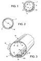
- FIG. 1 is illustrated a device for detection of an oil imbalance according to the first mode embodiment of the invention.
- the rotor 2 is provided with ribs 4 which are arranged substantially longitudinal and protrude into the interior of said rotor 2.
- the ribs 4 have a substantially quadrangular section. They comprise two lateral faces 42 which are adjacent to the inner surface 6 of the rotor, and a third face 44, intermediate between the two faces 42.
- the function of these ribs 4 is create open compartments 8.
- Each compartment 8 thus formed has as background a part of the surface internal rotor 6 between two ribs 4, and for walls the lateral faces 44 of the two ribs 4 between which he is.
- each face 42 and the intermediate face 44 of each rib 4 is produced, in the illustrated example, by a edge 46 which forms substantially a right angle. We could consider that said junction draws a edge that extends the intermediate face 44, of to increase the oil retention property compartment.
- FIG. 2 is illustrated a device for the detection of an unbalance of oil according to the second embodiment of the invention.
- the rotor 2 is provided of cavities 14 which are hollowed out in the thickness of the rotor 2 being open towards the inside of the rotor 2.
- cavities 14 have a curved section, which gives them a substantial lobe shape. They could have shapes different, chosen according to the constraints of manufacturing.
- the cavities 14 constitute open compartments 14. When a quantity of oil 100 has entered the rotor 2, it remains retained in one or more compartments 14 thus formed.
- the first and second embodiments of the device according to the invention which have just been described are both obtained by a modification of the geometry of the inner surface of the rotor 2.
- ribs 4 For the first embodiment, we realized a addition of material: ribs 4.
- cavities 14 For the second embodiment, a removal of subject matter: cavities 14.
- the geometry of the rotor 2 is modified while remaining symmetrical. The symmetry is achieved by creating an even number of compartments 8, 14 and arranging them in such a way that they are diametrically opposed two by two. Of preferably, they are arranged by being regularly distributed on the circumference of the inner surface 6 2. Their number is not critical. We could so consider a number of ribs 4 different from four, and a number of cavities 14 different from two.
- a sleeve is shown 24, intended to be removably inserted into inside a rotor, said rotor not being represent.
- the sheath 32 is dimensioned so as to fit inside the rotor and stay plated against it by centrifugal effect. So, during rotation, the rotor and the sleeve turn together.
- the sleeve 24 is provided with a chute 32 disposed in a substantially longitudinal direction said sheath 24, and projecting inwards of it.
- a chute 32 disposed in a substantially longitudinal direction said sheath 24, and projecting inwards of it.
- the chute 32 On one side of chute 32, and preferably near its base, the chute 32 has orifices 36 distributed over the length of it. The side on which the holes are 36 is chosen according to the direction of rotation of the rotor, as will be described later.
- the sleeve 32 also has a slot 26 disposed in a substantially longitudinal direction said sheath 32, being diametrically opposed to the trough 32.
- the edges 28 of the sheath 24 of part and else of the slot 26 are folded back on themselves, from to form an accumulation of matter diametrically opposed to the chute 32.
- the operation of the device according to third embodiment is as follows.
- the oil coming into the rotor is first gets stuck between the rotor and the sheath 24, and it is rotated, as shown by the arrow 52, in the opposite direction of the direction of rotation of the assembly constituted by the rotor and the sleeve 24.
- the oil hitherto stuck between the rotor and the sleeve 24 penetrates into the sleeve 24 by said slot 26.
- the orifices 36 of the chute 32 are pierced through it on its side that is upstream of the slot 26 if one moves in the direction of rotation of the assembly consisting of the rotor and the sheath 24. With this direction of rotation (arrow 50) and this position corresponding holes 36, the oil that has penetrated in the sheath 32 will lie against the side of the chute 32 on which the holes 36 are drilled. therefore, the oil passes through the wall of the sleeve 24 to through the orifices 36, as indicated by the arrows 54. She finds herself restrained between the sheath 24 and the rotor, in a compartment 34 formed between the chute 32 and the part of the rotor which is in vis-à-vis of the chute 34.
- this compartment 34 is a closed compartment. Oil is thus restrained, or trapped. She can not out of the compartment 34 through the orifices 36, since the chute 34 does not have any holes for exit on its side which is downstream of slot 26 if one circulates in the direction of rotation of the whole constituted by the rotor and the sheath 24.
- the oil inlet orifices 36 have a narrow and elongated shape, so that do not allow an accidental oil release to through them.
- edges 28 of the slot 26 are folded over themselves in such a way that their weight balances the chute weight 32 and amount of oil 100 trapped in the compartment 34, so as to form balancing means 28 of said chute 32 and trapped oil.
- the device according to the third mode of realization has the advantage of implementing a additional piece removable, the sheath, without having to modify the structure and / or the geometry of the rotor.
- Said sheath is preferably manufactured from a cylindrical sheet of circular section, which is stamped to form a chute longitudinal and that is slotted to form a slit longitudinal, the chute and the slot being diametrically opposite one another, the edges of the sheet on both sides of the slot are folded on themselves to the inside of the sheet, and holes are drilled on one side of the chute.
Landscapes
- Engineering & Computer Science (AREA)
- Physics & Mathematics (AREA)
- General Physics & Mathematics (AREA)
- Mechanical Engineering (AREA)
- General Engineering & Computer Science (AREA)
- Centrifugal Separators (AREA)
- Testing Of Balance (AREA)
- Structures Of Non-Positive Displacement Pumps (AREA)
Abstract
Description
- la figure 1 illustre, en coupe transversale, un premier mode de réalisation du dispositif selon l'invention ;
- la figure 2 illustre, en coupe transversale, un deuxième mode de réalisation du dispositif selon l'invention ;
- la figure 3 illustre, en coupe transversale et en perspective, un troisième mode de réalisation du dispositif selon l'invention.
Claims (11)
- Dispositif pour la détection d'un balourd d'huile à l'intérieur d'un rotor (2) d'une machine, caractérisé en ce qu'il comprend des moyens (4, 8, 14, 24, 34, 36) pour entraíner en rotation l'huile (100) présente dans le rotor (2), avec une vitesse de rotation de l'huile sensiblement égale à la vitesse de rotation dudit rotor.
- Dispositif selon la revendication 1, caractérisé en ce que lesdits moyens (4, 8, 14, 24, 34, 36) pour entraíner en rotation l'huile comprennent des moyens (4, 8, 14) pour piéger l'huile (100) contre le rotor (2) par effet centrifuge.
- Dispositif selon la revendication 2, caractérisé en ce que lesdits moyens (4, 8, 14, 24, 34, 36) pour piéger l'huile comprennent des compartiments (8, 14) répartis régulièrement sur la circonférence de la surface interne (6) du rotor (2).
- Dispositif selon la revendication 3, caractérisé en ce que lesdits compartiments (8) sont des compartiments ouverts sur l'intérieur du rotor (2), formés par la surface interne (6) dudit rotor (2) et par des nervures (4) sensiblement longitudinales disposées sur la surface interne (6) dudit rotor (2).
- Dispositif selon la revendication 3, caractérisé en ce que lesdits compartiments (14) sont des compartiments ouverts sur l'intérieur du rotor (2), formés par des cavités (14) creusées dans l'épaisseur du rotor (2) à partir de la surface interne (6) de celui-ci.
- Dispositif selon la revendication 2, caractérisé en ce que lesdits moyens (4, 8, 14, 24, 34, 36) pour piéger l'huile comprennent un fourreau (24) amovible inséré à l'intérieur du rotor (2) et qui tourne avec le rotor (2) par effet centrifuge, et en ce que ledit fourreau (24) comporte une goulotte (34) sensiblement longitudinale agencée de manière à faire saillie vers l'intérieur dudit fourreau (24) et des moyens d'équilibrage (28) de ladite goulotte (34), ainsi que des moyens d'entrée d'huile (36) à travers ladite goulotte (34).
- Dispositif selon la revendication 6, caractérisé en ce que lesdits moyens d'entrée d'huile (36) comportent des orifices (36) qui sont agencés sur un même côté de ladite goulotte (34).
- Dispositif selon la revendication 6 ou 7, caractérisé en ce que ledit fourreau (24) comporte une fente (26) longitudinale disposée de manière sensiblement diamétralement opposée à ladite goulotte (34), et en ce que lesdits moyens d'équilibrage (28) de la goulotte (34) comportent des bords longitudinaux (28) repliés de ladite fente (26).
- Dispositif selon la revendication 8, caractérisé en ce que le fourreau (24) est fabriqué à partir d'une tôle cylindrique de section circulaire, qui est emboutie en creux pour former une goulotte longitudinale (34) et qui est fendue pour former une fente longitudinale (26), la goulotte (34) et la fente (26) étant diamétralement opposées l'une à l'autre, les bords de la tôle de part et d'autre de la fente (26) sont repliés sur eux-mêmes vers l'intérieur de la tôle, et des orifices (36) sont percés sur un seul côté de la goulotte (34).
- Rotor (2), caractérisé en ce qu'il est équipé d'un dispositif pour la détection d'un balourd d'huile selon l'une quelconque des revendications 1 à 9.
- Machine, caractérisée en ce qu'elle est équipée d'un rotor (2) selon la revendication 10.
Applications Claiming Priority (2)
| Application Number | Priority Date | Filing Date | Title |
|---|---|---|---|
| FR0350606A FR2860276B1 (fr) | 2003-09-25 | 2003-09-25 | Dispositif pour la detection d'un balourd d'huile dans un rotor, rotor comportant un tel dispositif, et machine equipee d'un tel rotor |
| FR0350606 | 2003-09-25 |
Publications (1)
| Publication Number | Publication Date |
|---|---|
| EP1519179A1 true EP1519179A1 (fr) | 2005-03-30 |
Family
ID=34179013
Family Applications (1)
| Application Number | Title | Priority Date | Filing Date |
|---|---|---|---|
| EP04104565A Withdrawn EP1519179A1 (fr) | 2003-09-25 | 2004-09-21 | Dispositif pour la détection d'un balourd d'huile dans un rotor, rotor comportant un tel dispositif, et machine équipée d'un tel rotor |
Country Status (7)
| Country | Link |
|---|---|
| US (1) | US7036371B2 (fr) |
| EP (1) | EP1519179A1 (fr) |
| JP (1) | JP2005121011A (fr) |
| CN (1) | CN1580736A (fr) |
| CA (1) | CA2482144A1 (fr) |
| FR (1) | FR2860276B1 (fr) |
| RU (1) | RU2004128440A (fr) |
Cited By (1)
| Publication number | Priority date | Publication date | Assignee | Title |
|---|---|---|---|---|
| FR2999643A1 (fr) * | 2012-12-17 | 2014-06-20 | Snecma | Systeme de surveillance de quantite d'huile par balourd d'huile |
Families Citing this family (2)
| Publication number | Priority date | Publication date | Assignee | Title |
|---|---|---|---|---|
| FR2926602B1 (fr) * | 2008-01-23 | 2010-03-26 | Snecma | Dispositif d'amortissement des vibrations d'un rotor de turbomachine |
| CN103217255B (zh) * | 2013-03-12 | 2015-08-12 | 中国航空工业集团公司沈阳发动机设计研究所 | 一种航空类产品的本机平衡方法 |
Citations (1)
| Publication number | Priority date | Publication date | Assignee | Title |
|---|---|---|---|---|
| WO2001086130A1 (fr) * | 2000-05-09 | 2001-11-15 | Turbec Ab | Unite rotor et procede d'equilibrage correspondant |
-
2003
- 2003-09-25 FR FR0350606A patent/FR2860276B1/fr not_active Expired - Fee Related
-
2004
- 2004-09-10 US US10/937,389 patent/US7036371B2/en not_active Expired - Fee Related
- 2004-09-17 JP JP2004271135A patent/JP2005121011A/ja active Pending
- 2004-09-21 CN CNA2004100782772A patent/CN1580736A/zh active Pending
- 2004-09-21 EP EP04104565A patent/EP1519179A1/fr not_active Withdrawn
- 2004-09-22 CA CA002482144A patent/CA2482144A1/fr not_active Abandoned
- 2004-09-24 RU RU2004128440/06A patent/RU2004128440A/ru not_active Application Discontinuation
Patent Citations (1)
| Publication number | Priority date | Publication date | Assignee | Title |
|---|---|---|---|---|
| WO2001086130A1 (fr) * | 2000-05-09 | 2001-11-15 | Turbec Ab | Unite rotor et procede d'equilibrage correspondant |
Cited By (1)
| Publication number | Priority date | Publication date | Assignee | Title |
|---|---|---|---|---|
| FR2999643A1 (fr) * | 2012-12-17 | 2014-06-20 | Snecma | Systeme de surveillance de quantite d'huile par balourd d'huile |
Also Published As
| Publication number | Publication date |
|---|---|
| CA2482144A1 (fr) | 2005-03-25 |
| CN1580736A (zh) | 2005-02-16 |
| FR2860276A1 (fr) | 2005-04-01 |
| US7036371B2 (en) | 2006-05-02 |
| RU2004128440A (ru) | 2006-03-10 |
| US20050069439A1 (en) | 2005-03-31 |
| JP2005121011A (ja) | 2005-05-12 |
| FR2860276B1 (fr) | 2005-12-02 |
Similar Documents
| Publication | Publication Date | Title |
|---|---|---|
| CA2946958C (fr) | Module de turbomachine comportant un carter autour d'un equipement avec un capot de recuperation d'huile de lubrification | |
| CA2757288A1 (fr) | Aube de turbine avec un trou de depoussierage en base de pale | |
| WO2015110744A1 (fr) | Enceinte de palier d'une turbomachine | |
| WO2020249686A1 (fr) | Dispositif d'équilibrage dynamique pour rotor | |
| EP2071141A1 (fr) | Étanchéité de fixation de support de palier dans une turbomachine | |
| FR3084407A1 (fr) | Gouttiere de canalisation d'huile de lubrification d'une turbomachine d'aeronef | |
| CA2876347C (fr) | Tourillon de turbomachine comportant une couronne de recuperation d'un flux d'huile de lubrification avec une pluralite d'orifices d'evacuation d'huile de lubrification | |
| FR2859002A1 (fr) | Dispositif abradable sur carter de soufflante d'un moteur de turbine a gaz | |
| FR2964942A1 (fr) | Enceinte de protection des pignons de commande du pas d'une helice d'open-rotor | |
| FR2996875A1 (fr) | Installation de mesures pour des essais de rupture d'aube sur une turbomachine | |
| FR3027628B1 (fr) | Capot de recuperation d’huile de lubrification pour un equipement de turbomachine | |
| FR2860276A1 (fr) | Dispositif pour la detection d'un balourd d'huile dans un rotor, rotor comportant un tel dispositif, et machine equipee d'un tel rotor | |
| FR2967748A1 (fr) | Systeme d'etancheite a joint annulaire a brosse | |
| FR3016406A1 (fr) | Ensemble de turbomachine comportant deux corps et des moyens de guidage d'un fluide d'ecoulement d'un corps a l'autre | |
| FR2972492A1 (fr) | Turbomachine comportant une vanne anti-pompage | |
| FR3008448A1 (fr) | Dispositif de depose pour aubes | |
| FR3056629A1 (fr) | Element d'essai pour modeliser une aube ou une pale d'un rotor, rotor comportant ledit element d'essai | |
| EP3131656B1 (fr) | Filtrage d'un flux gaz/particules | |
| FR3135110A1 (fr) | Turbomachine aéronautique à dispositif d’équilibrage amélioré et procédé d’équilibrage de la turbomachine | |
| EP4022176A1 (fr) | Agencement de turbine intégrant une rigole circonférentielle de récupération d'huile | |
| FR3100843A1 (fr) | Support de palier de turbomachine à récupération d’huile améliorée | |
| FR3075252A1 (fr) | Ensemble d'etancheite | |
| CA2952755C (fr) | Arbre de turbomachine | |
| FR3030616A1 (fr) | Support de palier pour turbomachine, notamment turboreacteur | |
| CA2858165A1 (fr) | Bandes d'amortissement de vibrations a evacuation de fluides, pour protection acoustique de carter de soufflante de turbomachine d'aeronef |
Legal Events
| Date | Code | Title | Description |
|---|---|---|---|
| PUAI | Public reference made under article 153(3) epc to a published international application that has entered the european phase |
Free format text: ORIGINAL CODE: 0009012 |
|
| AK | Designated contracting states |
Kind code of ref document: A1 Designated state(s): AT BE BG CH CY CZ DE DK EE ES FI FR GB GR HU IE IT LI LU MC NL PL PT RO SE SI SK TR |
|
| AX | Request for extension of the european patent |
Extension state: AL HR LT LV MK |
|
| RIN1 | Information on inventor provided before grant (corrected) |
Inventor name: FRANCHET, MICHEL, FRANEOIS, RAYMOND Inventor name: FOREST, FRANCIS, ROBERT |
|
| 17P | Request for examination filed |
Effective date: 20050603 |
|
| RAP1 | Party data changed (applicant data changed or rights of an application transferred) |
Owner name: SNECMA |
|
| AKX | Designation fees paid |
Designated state(s): DE FR GB |
|
| GRAP | Despatch of communication of intention to grant a patent |
Free format text: ORIGINAL CODE: EPIDOSNIGR1 |
|
| STAA | Information on the status of an ep patent application or granted ep patent |
Free format text: STATUS: THE APPLICATION IS DEEMED TO BE WITHDRAWN |
|
| 18D | Application deemed to be withdrawn |
Effective date: 20060823 |