EP1519089A1 - Valve and method for a pressure-tight, low-friction arrangement of a spool in a housing - Google Patents
Valve and method for a pressure-tight, low-friction arrangement of a spool in a housing Download PDFInfo
- Publication number
- EP1519089A1 EP1519089A1 EP04104635A EP04104635A EP1519089A1 EP 1519089 A1 EP1519089 A1 EP 1519089A1 EP 04104635 A EP04104635 A EP 04104635A EP 04104635 A EP04104635 A EP 04104635A EP 1519089 A1 EP1519089 A1 EP 1519089A1
- Authority
- EP
- European Patent Office
- Prior art keywords
- valve
- valve housing
- spool
- housing
- adjacent
- Prior art date
- Legal status (The legal status is an assumption and is not a legal conclusion. Google has not performed a legal analysis and makes no representation as to the accuracy of the status listed.)
- Granted
Links
Images
Classifications
-
- F—MECHANICAL ENGINEERING; LIGHTING; HEATING; WEAPONS; BLASTING
- F16—ENGINEERING ELEMENTS AND UNITS; GENERAL MEASURES FOR PRODUCING AND MAINTAINING EFFECTIVE FUNCTIONING OF MACHINES OR INSTALLATIONS; THERMAL INSULATION IN GENERAL
- F16K—VALVES; TAPS; COCKS; ACTUATING-FLOATS; DEVICES FOR VENTING OR AERATING
- F16K27/00—Construction of housing; Use of materials therefor
- F16K27/04—Construction of housing; Use of materials therefor of sliding valves
- F16K27/041—Construction of housing; Use of materials therefor of sliding valves cylindrical slide valves
-
- F—MECHANICAL ENGINEERING; LIGHTING; HEATING; WEAPONS; BLASTING
- F16—ENGINEERING ELEMENTS AND UNITS; GENERAL MEASURES FOR PRODUCING AND MAINTAINING EFFECTIVE FUNCTIONING OF MACHINES OR INSTALLATIONS; THERMAL INSULATION IN GENERAL
- F16K—VALVES; TAPS; COCKS; ACTUATING-FLOATS; DEVICES FOR VENTING OR AERATING
- F16K11/00—Multiple-way valves, e.g. mixing valves; Pipe fittings incorporating such valves
- F16K11/02—Multiple-way valves, e.g. mixing valves; Pipe fittings incorporating such valves with all movable sealing faces moving as one unit
- F16K11/06—Multiple-way valves, e.g. mixing valves; Pipe fittings incorporating such valves with all movable sealing faces moving as one unit comprising only sliding valves, i.e. sliding closure elements
- F16K11/065—Multiple-way valves, e.g. mixing valves; Pipe fittings incorporating such valves with all movable sealing faces moving as one unit comprising only sliding valves, i.e. sliding closure elements with linearly sliding closure members
- F16K11/07—Multiple-way valves, e.g. mixing valves; Pipe fittings incorporating such valves with all movable sealing faces moving as one unit comprising only sliding valves, i.e. sliding closure elements with linearly sliding closure members with cylindrical slides
Landscapes
- Engineering & Computer Science (AREA)
- General Engineering & Computer Science (AREA)
- Mechanical Engineering (AREA)
- Multiple-Way Valves (AREA)
- Sliding Valves (AREA)
Abstract
Description
Die Anmeldung bezieht sich auf ein Ventil sowie ein Verfahren zu einer druckdichten, reibungsarmen Anordnung eines dazugehörigen Ventilschiebers in einem Gehäuse gemäß dem Oberbegriff des Anspruchs 1 bzw. 13. The application relates to a valve and a method for a pressure-tight, low-friction arrangement of an associated valve spool in a housing according to the preamble of claim 1 or 13th
Auf dem hier interessierenden Gebiet von Schieberventilen unterscheidet man bezüglich der Dichtung zwei Typen von Ventilen, nämlich Ventile, die über einen Dichtring verfügen (der entweder am Ventilschieber oder am Dichtgehäuse angebracht sein kann) und Ventile, bei denen kein Dichtring vorgesehen ist. Bei Ventilen des letztgenannten Typs ist es von eminenter Bedeutung, dass der Ventilschieber und der Innenraum des den Ventilschieber umgebenden Ventilgehäuses möglichst passgenau sein müssen, da die Reibung und die Druckdichtheit eines Schieberventils dann im Wesentlichen vom Spaltmaß zwischen Gehäuse und Schieber abhängig sind.In the field of slide valves of interest one distinguishes in relation to the Seal two types of valves, namely valves that have a sealing ring (the can be mounted either on the valve spool or on the sealing housing) and valves, at where no sealing ring is provided. For valves of the latter type it is from eminent importance that the valve spool and the interior of the valve spool surrounding valve housing must be as accurate as possible, since the friction and the Pressure tightness of a slide valve then essentially from the gap between housing and slides are dependent.
Die bisherigen Lösungsansätze auf diesem Gebiet waren zum Einen, dass der Schieber und das Gehäuse paarig eingeschliffen wurden, oder dass der Schieber und das Gehäuse mit einer sehr geringen Toleranz, die häufig nur zwischen 0,001 und 0,002 mm betrug, zueinander passend gefertigt wurden. Diese Lösungen sind zum einen jedoch sehr zeit- und materialintensiv, zum Anderen erfordert dies höchste Präzision, ohne dass in allen Fällen wirklich zufriedenstellende Passgenauigkeiten erreicht werden können.The previous solutions in this area were, on the one hand, that the slide and the housing were ground in pairs, or that the slider and the housing with a very low tolerance, which was often only between 0.001 and 0.002 mm, to each other were made to match. These solutions are on the one hand, however, very time and material intensive, on the other hand this requires the highest precision, without in all cases really satisfactory accuracy of fit can be achieved.
Es stellt sich daher die Aufgabe, eine Vorrichtung sowie ein Verfahren zu einer druckdichten, reibungsarmen Anordnung eines Ventilschiebers in einem Gehäuse zu schaffen, bei der eine druckdichte und reibungsarme Einpassung des Ventilschiebers in das Ventilgehäuse auf einfache Weise erreicht werden kann.It is therefore the object, a device and a method for a pressure-tight, to provide low-friction arrangement of a valve spool in a housing, in which a pressure-tight and low-friction fit of the valve spool in the valve body on easy way can be achieved.
Zur Lösung dieser Aufgabe wird ein Ventil mit den Merkmalen des Anspruchs 1 sowie ein
Verfahren zu einer druckdichten, reibungsarmen Anordnung eines Ventilschiebers in einem
Gehäuse mit den Merkmalen des Anspruchs 7 vorgeschlagen.To solve this problem, a valve with the features of claim 1 and a
Method for a pressure-tight, low-friction arrangement of a valve spool in one
Housing proposed with the features of
Gemäß Anspruch 1 umfasst ein erfindungsgemäßes Ventil einen Ventilschieber sowie ein im zusammengesetzten Zustand den Ventilschieber umgebendes Ventilgehäuse mit einer röhrenförmig verlaufenden Innenaussparung und ist dadurch gekennzeichnet, dass das Ventilschiebermaterial zumindest in den im zusammengesetzten Zustand an das Ventilgehäuse angrenzenden Bereichen ein geringeres Elastizitätsmodul und einen höheren Wärmeausdehnungskoeffizienten besitzt als das an die Innenaussparung des Ventilgehäuses angrenzende Ventilgehäusematerial.According to claim 1, a valve according to the invention comprises a valve spool and a in assembled state surrounding the valve spool valve housing with a tubular inner recess and is characterized in that the Valve slide material at least in the assembled state of the Valve housing adjacent areas a lower modulus of elasticity and a higher Thermal expansion coefficient than that on the inner recess of the valve housing adjacent valve housing material.
Das an die Innenaussparung des Ventilgehäuses angrenzende Ventilgehäusematerial besitzt vorzugsweise ein Elastizitätsmodul von ≥ 0,5 x 10⁻⁵ N/mm2 bis ≤ 10 x 10-5 N/mm2, noch bevorzugt von ≥ 0,75 x 10⁻⁵ N/mm2 bis ≤ 7,5 x 10⁻⁵ N/mm2, noch bevorzugt von ≥ 1 x 10⁻⁵ N/mm2 bis ≤ 5 x 10⁻⁵ N/mm2, noch bevorzugt von ≥ 1,25 x 10⁻⁵ N/mm2 bis ≤ 3 x 10⁻⁵ N/mm2 sowie am meisten bevorzugt von ≥ 1,5 x 10⁻⁵ N/mm2 bis ≤ 2,5 x 10⁻⁵ N/mm2.The valve housing material adjoining the inner recess of the valve housing preferably has a modulus of elasticity of ≥ 0.5 × 10 -5 N / mm 2 to ≦ 10 × 10 -5 N / mm 2 , more preferably 0.75 × 10 -5 N / mm 2 to ≤ 7.5 x 10 -5 N / mm 2 , more preferably from ≥ 1 x 10 -5 N / mm 2 to ≤ 5 x 10 -5 N / mm 2 , still preferably ≥ 1.25 x 10 -5 N / mm 2 to ≤ 3 x 10 -5 N / mm 2, and most preferably from ≥ 1.5 x 10 -5 N / mm 2 to ≤ 2.5 x 10 -5 N / mm 2 .
Das Ventilschiebermaterial besitzt zumindest in den im zusammengesetzten Zustand an das Ventilgehäuse angrenzenden Bereichen vorzugsweise ein Elastizitätsmodul von Elastizitätsmodul von ≥ 0,25 x 10⁻⁷ N/mm2 bis ≤ 10 x 10-7 N/mm2, noch bevorzugt von ≥ 0,35 x 10⁻⁷ N/mm2 bis ≤ 7,5 x 10⁻⁷ N/mm2, noch bevorzugt von ≥ 0,5 x 10⁻⁷ N/mm2 bis ≤ 5 x 10⁻⁷ N/mm2, noch bevorzugt von ≥ 0,6 x 10⁻⁷ N/mm2 bis ≤ 3 x 10⁻⁷ N/mm2 sowie am meisten bevorzugt von ≥ 0,75 x 10⁻⁷ N/mm2 bis ≤ 2,5 x 10⁻⁷ N/mm2.The valve gate material preferably has a Young's modulus of elastic modulus of ≥ 0.25 × 10 -7 N / mm 2 to ≤ 10 × 10 -7 N / mm 2 , more preferably ≥ 0, at least in the regions adjacent to the valve housing in the assembled state. 35 × 10 -7 N / mm 2 to ≦ 7.5 × 10 -7 N / mm 2 , more preferably from ≥ 0.5 × 10 -7 N / mm 2 to ≦ 5 × 10 -7 N / mm 2 , still more preferably from ≥ 0.6 x 10 -7 N / mm 2 to ≦ 3 x 10 -7 N / mm 2, and most preferably from ≥ 0.75 x 10 -7 N / mm 2 to ≦ 2.5 x 10 -7 N / mm 2 .
Das Verhältnis von Elastizitätsmodul des an die Innenaussparung des Ventilgehäuses angrenzende Ventilgehäusematerials zu Elastizitätsmodul des Ventilschiebermaterial zumindest in den im zusammengesetzten Zustand an das Ventilgehäuse angrenzenden Bereichen ist bevorzugt von ≥1:10 bis ≤ 1:1000, noch bevorzugt von ≥1:25 bis ≤ 1:750, noch bevorzugt von ≥1:50 bis ≤ 1:500, noch bevorzugt von ≥1:75 bis ≤ 1:300, sowie am meisten bevorzugt von bevorzugt von ≥1:100 bis ≤ 1:200.The ratio of modulus of elasticity of the inner recess of the valve housing adjacent valve body material to modulus of elasticity of the valve gate material at least in the assembled state of the valve housing adjacent Ranges is preferably from ≥1: 10 to ≤1: 1000, still preferably from ≥1: 25 to ≤1: 750, still preferably from ≥1: 50 to ≤1: 500, more preferably from ≥1: 75 to ≤1: 300, and most preferably from ≥1: 100 to ≤1: 200.
Das an die Innenaussparung des Ventilgehäuses angrenzende Ventilgehäusematerial besitzt vorzugsweise einen Wärmeausdehnungskoeffizienten von ≥ 1 x 10⁻⁶ 1/K bis ≤ 100 x 10-6 1/K, noch bevorzugt von ≥ 2,5 x 10⁻⁶ 1/K bis ≤ 75 x 10-6 1/K, noch bevorzugt von ≥ 5 x 10⁻⁶ N/mm2 bis ≤ 50 x 10-6 1/K, noch bevorzugt von ≥ 10 x 10-6 1/K bis ≤ 25 x 10-5 1/K sowie am meisten bevorzugt von ≥ 12 x 10-6 1/K bis ≤ 20 x 10-6 1/K.The valve housing material adjoining the inner recess of the valve housing preferably has a thermal expansion coefficient of ≥ 1 × 10 -6 1 / K to ≦ 100 × 10 -6 1 / K, more preferably 2.5 × 10 -6 1 / K to ≦ 75 x 10 -6 1 / K, more preferably from ≥ 5 x 10 -6 N / mm 2 to ≤ 50 x 10 -6 1 / K, more preferably from ≥ 10 x 10 -6 1 / K to ≤ 25 x 10 - 5 1 / K and most preferably from ≥ 12 x 10 -6 1 / K to ≤ 20 x 10 -6 1 / K.
Das Ventilschiebermaterial besitzt zumindest in den im zusammengesetzten Zustand an das Ventilgehäuse angrenzenden Bereichen vorzugsweise einen Wärmeausdehnungskoeffizienten von ≥ 1 x 10⁻⁵ 1/K bis ≤ 100 x 10-5 1/K, noch bevorzugt von ≥ 2,5 x 10⁻⁵ 1/K bis ≤ 75 x 10-5 1/K, noch bevorzugt von ≥ 5 x 10⁻⁵ N/mm2 bis ≤ 60 x 10-5 1/K, noch bevorzugt von ≥ 10 x 10-5 1/K bis ≤ 40 x 10-5 1/K sowie am meisten bevorzugt von ≥ 12 x 10-5 1/K bis ≤ 30 x 10-5 1/K.The valve slide material preferably has a coefficient of thermal expansion of at least den 1 × 10 -5 1 / K to ≦ 100 × 10 -5 1 / K, more preferably 2.5 × 10 -5 1, at least in the regions adjoining the valve housing in the assembled state / K to ≤ 75 x 10 -5 1 / K, more preferably from ≥ 5 x 10 -5 N / mm 2 to ≤ 60 x 10 -5 1 / K, more preferably from ≥ 10 x 10 -5 1 / K to ≤ 40 x 10 -5 1 / K and most preferably from ≥ 12 x 10 -5 1 / K to ≤ 30 x 10 -5 1 / K.
Das Verhältnis von Wärmeausdehnungskoeffizient des an die Innenaussparung des Ventilgehäuses angrenzende Ventilgehäusematerials zu Wärmeausdehnungskoeffizient des Ventilschiebermaterial zumindest in den im zusammengesetzten Zustand an das Ventilgehäuse angrenzenden Bereichen ist bevorzugt von >1:1 bis ≤ 1:100, noch bevorzugt von ≥1:2 bis ≤ 1:75, noch bevorzugt von ≥1:5 bis ≤ 1:50, noch bevorzugt von ≥1:7,5 bis ≤ 1:25, sowie am meisten bevorzugt von bevorzugt von ≥1:10 bis ≤ 1:15.The ratio of coefficient of thermal expansion of the internal recess of the Valve body adjacent valve housing material to the coefficient of thermal expansion of Valve slide material at least in the assembled state of the Valve housing adjacent areas is preferably from> 1: 1 to ≤ 1: 100, still preferred from ≥1: 2 to ≤1.75, more preferably from ≥1: 5 to ≤150, still more preferably from ≥1: 7.5 to ≤ 1:25, and most preferably from ≥1: 10 to ≤1.15.
In einer bevorzugten Ausführungsform besitzt der Ventilschieber im Ausgangszustand einen größeren radialen Maximaldurchmesser als der Durchmesser der Innenaussparung des Ventilgehäuses und ist durch Erwärmung über den Fließpunkt des Schiebermaterials des Bereichs des Ventilschiebers, welcher im zusammengesetzten Zustand an das Ventilgehäuse angrenzt sowie anschließender Abkühlung in die Innenaussparung einpaßbar.In a preferred embodiment, the valve slide in the initial state has a larger radial maximum diameter than the diameter of the inner recess of the Valve housing and is by heating above the pour point of the valve material of the Area of the valve spool, which in the assembled state to the valve housing adjoins and subsequent cooling in the inner recess einpaßbar.
In einer weiteren bevorzugten Ausführungsform besteht das Gehäuse aus einem metallischen Material besteht, welches vorzugsweise in einem Sinterverfahren hergestellt wird. In a further preferred embodiment, the housing consists of a metallic Material consists, which is preferably produced in a sintering process.
In einer weiteren bevorzugten Ausführungsform besteht der Ventilschieber zumindest in Teilbereichen aus einem thermoplastischen Material, welches vorzugsweise durch Spritzguss ausgeformt wird.In a further preferred embodiment, the valve slide is at least in Subregions of a thermoplastic material, which preferably by injection molding is formed.
In einer weiteren bevorzugten Ausführungsform ist der Ventilschieber nur in den im zusammengesetzten Zustand an das Ventilgehäuse angrenzenden Bereichen aus einem Material, welches ein geringeres Elastizitätsmodul und einen höheren Wärmeausdehnungskoeffizienten besitzt als das an die Innenaussparung des Ventilgehäuses angrenzende Ventilgehäusematerial, in den übrigen Bereichen aber aus einem ähnlichen oder dem gleichen Material wie das an die Innenaussparung des Ventilgehäuses angrenzende Ventilgehäusematerial. Bevorzugt werden die erstgenannten Bereiche auf den Ventilgrundkörper (d.h. die übrigen Bereiche des Ventilschiebers) aufgebracht, vorzugsweise aufgespritzt oder aufgeschnappt.In a further preferred embodiment, the valve spool is only in the in assembled state to the valve housing adjacent areas of a Material, which has a lower modulus of elasticity and a higher Thermal expansion coefficient than that on the inner recess of the valve housing adjacent valve housing material, in the remaining areas but from a similar or the same material as the adjacent to the inner recess of the valve housing Valve housing material. Preference is given to the former areas on the Valve body (i.e., the remaining portions of the valve spool) is applied, preferably splashed or snapped.
Gemäß Anspruch 7 umfasst ein Verfahren zur druckdichten, reibungsarmen Anordnung eines
Ventilschiebers in einem Ventilgehäuse eines erfindungsgemäßen Ventils die Schritte:
Gemäß einer bevorzugten Ausführungsform des Verfahrens wird dabei die in Schritt (b) zugeführte Wärmemenge und/oder die Zeitspanne des Erwärmens so bemessen, dass sich nach dem Abkühlen ein gewünschtes Spaltmaß zwischen Ventilschieber und Ventilgehäuse einstellt. According to a preferred embodiment of the method, in step (b) supplied amount of heat and / or the period of heating so measured that after cooling, a desired gap between valve spool and valve housing established.
Beim Einpressen des Ventilschiebers, dessen Material zumindest in den im zusammengesetzten Zustand an das Ventilgehäuse angrenzenden Bereichen ein geringeres Elastizitätsmodul und einen höheren Wärmeausdehnungskoeffizienten besitzt als das an die Innenaussparung des Ventilgehäuses angrenzende Ventilgehäusematerial, in das Ventilgehäuse werden diese Bereiche unter Spannung gesetzt. Zum Abbau dieser Spannung werden nun Ventilschieber und Ventilgehäuse soweit erwärmt, bis die Fließspannungen (erzeugt durch die unterschiedlichen Wärmeausdehnungskoeffizienten der beiden Materialien) erreicht wird und es zu einer plastischen Verformung in den vorgespannten Bereichen des Schiebers kommt. Jedoch bleibt eine elastische Restvorspannung auch in dem erwärmten Zustand bestehen. Da die obengenannten Bereiche des Ventilschiebers jedoch über einen höheren Wärmeausdehnungskoeffizienten verfügen als die angrenzenden Bereiche des Ventilgehäuses, werden diese beim Abkühlen auch eine stärkere Materialwärmeänderung durchlaufen, wodurch die Spannung zwischen Ventilschieber und Ventilgehäuse im Wesentlichen beseitigt werden können. Somit wird durch einfaches Erwärmen und Abkühlen eine Einpassung des Ventilschiebers in das Ventilgehäuse erreicht.When pressing the valve spool whose material at least in the compound state to the valve housing adjacent areas a lesser Elastic modulus and has a higher coefficient of thermal expansion than that of the Inner recess of the valve housing adjacent valve housing material into the Valve body these areas are put under tension. To reduce this tension now valve spool and valve housing are heated until the yield stress (generated by the different thermal expansion coefficients of the two Materials) is reached and it is a plastic deformation in the prestressed Areas of the slider comes. However, an elastic residual prestress also remains in the heated condition exist. However, since the above areas of the valve spool over have a higher thermal expansion coefficient than the adjacent areas of the Valve housing, these are on cooling also a stronger material heat change through, whereby the tension between valve spool and valve housing in Can be substantially eliminated. Thus, by simply heating and cooling achieved a fit of the valve spool in the valve housing.
Dadurch dass das entstehende Spaltmaß im Wesentlichen aus zum Einen durch das Wechselspiel zwischen den unterschiedlichen Wärmeausdehnungskoeffizienten und Elastizitätsmodule der aneinander angrenzenden Materialen sowie zum Anderen durch die zugeführte Wärmemenge und/ oder die Zeitspanne der Erwärmung resultiert, ergibt sich folgendes:
- Die Fertigungstoleranzen von Ventilgehäuse und/oder Ventilschieber können
großzügiger bemessen sein, da die Fertigungstoleranzen das entstehende Spaltmaß
nicht oder nur stark eingeschränkt beeinflussen. In der Praxis können bei gleichem
erzielbaren Spaltmaß die Fertigungstoleranzen um den
Faktor 50 größer sein. - Eine evtl. mechanisch durchgeführte Passung von Ventilgehäuse und/oder Ventilschieber aneinander durch Läppen, Polieren, Schleifen o.ä. erübrigt sich
- Das Spaltmaß kann bei bekannten Materialcharakteristika einfach durch kontrollierte Erwärmung genau eingestellt werden, so dass Ventile mit verbesserten Eigenschaften zugänglich sind.
- Als weiterer Vorteil kann der Schieber ohne spannende Nacharbeit in einem Spritzgussverfahren und das Gehäuse in einem Sinterverfahren hergestellt werden.
- The manufacturing tolerances of the valve housing and / or valve spool can be more generously dimensioned, since the manufacturing tolerances do not or only to a very limited extent influence the resulting gap. In practice, with the same achievable gap size, the manufacturing tolerances can be larger by a factor of 50.
- A possibly mechanically performed fit of valve housing and / or valve slide to each other by lapping, polishing, grinding or similar. is unnecessary
- The gap size can be accurately adjusted with known material characteristics simply by controlled heating, so that valves with improved properties are accessible.
- As a further advantage, the slider can be produced without exciting rework in an injection molding process and the housing in a sintering process.
Die vorgenannten sowie die beanspruchten und in dem Ausführungsbeispiel beschriebenen erfindungsgemäß zu verwendenden Bauteile unterliegen in ihrer Größe, Formgestaltung, Materialauswahl und technischen Konzeption keinen besonderen Ausnahmebedingungen, so dass die in diesem Anwendungsgebiet bekannten Auswahlkriterien uneingeschränkt Anwendung finden können.The aforementioned and the claimed and described in the embodiment According to the invention components to be used are subject in size, shape design, Material selection and technical conception no special exceptions, so that the selection criteria known in this field of application are unrestricted Application can be found.
Weitere Einzelheiten, Merkmale und Vorteile des Gegenstands der Erfmdung ergeben sich aus den Unteransprüchen sowie aus der nachfolgenden Beschreibung der zugehörigen Zeichnungen, in denen - beispielhaft - ein Ausführungsbeispiel des erfindungsgemäßen Ventils dargestellt ist.Further details, features and advantages of the subject matter of the invention result from the dependent claims and from the following description of the associated Drawings in which - by way of example - an embodiment of the invention Valve is shown.
In der Zeichnung zeigen:
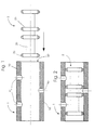
- Fig. 1
- einen schematischen Querschnitt durch einen erfindungsgemäßen Ventilschieber und ein Ventilgehäuse vor dem Einpassen des Ventilschiebers in das Ventilgehäuse; sowie
- Fig. 2
- einen schematischen Querschnitt durch einen erfindungsgemäßen Ventilschieber und ein Ventilgehäuse nach dem Einpassen des Ventilschiebers in das Ventilgehäuse.
- Fig. 1
- a schematic cross section through a valve spool according to the invention and a valve housing before fitting the valve spool in the valve housing; such as
- Fig. 2
- a schematic cross section through a valve spool according to the invention and a valve housing after fitting the valve spool in the valve housing.
Wie in Fig. 1 und 2 zu sehen, beinhaltet ein erfindungsgemäßes Ventil ein Ventilgehäuse 1
und einen Ventilschieber 2. Der Übersichtlichkeit halber wurden zusätzliche benötigte - an
sich bekannte - Komponenten des Ventils weggelassen.As can be seen in FIGS. 1 and 2, a valve according to the invention includes a valve housing 1
and a
Das Ventilgehäuse 1 besteht vorzugsweise aus einem metallischen Material 10 und weist
mehrere Steuerkanäle 40 auf, die durch den Ventilschieber 2 steuerbar sind, sowie eine
rohrförmige Innenaussparung (Innenkanal) 50 auf. Bevorzugt ist das Ventilgehäuse durch ein
Metal-Injection-Moulding (MIM)-Verfahren herstellbar. In den Figuren besteht das
Ventilgehäuse 1 aus einem einheitlichen Material 10, jedoch kann das Ventilgehäuse auch aus
zwei oder mehr Schichten oder Bereichen unterschiedlichen Materials bestehen. Bevorzugt ist
jedoch zumindest der Bereich des Ventilgehäuses, der an den Innenkanal 50 angrenzt, aus
einem einheitlichen Material 10 gefertigt.The valve housing 1 is preferably made of a
Der Ventilschieber 2 besteht aus einem Ventilgrundkörper 20, welcher eine oder mehrere (in
dieser Ausführungsform vier) Schiebersitzflächen 25 umfaßt. In dieser Ausführungsform ist
radial auswärts der Schiebersitzflächen 25 eine Schicht 30 eines zweiten Materials
aufgebracht, welches ein kleineres Elastizitätsmodul, aber eine größere Wärmedehnung
besitzt als das Ventilgehäusematerial 10. Das zweite Material ist bevorzugt ein
thermoplastisches Material. Bevorzugt wird es durch Aufspritzen oder Aufschnappen auf den
Ventilgrundkörper 20 aufgebracht.The
In der in Fig. 1 und 2 gezeigten Ausführungsform besteht der Bereich des Ventilschiebers 30,
der im zusammengebauten Zustand an das Ventilgehäuse 1 angrenzt, aus einem anderen
Material als der Ventilgrundkörper 20 und die Schiebersitzflächen 25. In einer bevorzugten
Ausführungsform der Erfindung bestehen Ventilgrundkörper 20 und Schiebersitzflächen 25
aus demselben oder einem ähnlichen Material wie das Ventilgehäuse 10. Jedoch kann auch
der gesamte Ventilschieber aus einem einheitlichen Material bestehen, oder für den
Ventilgrundkörper 20 und/oder die Schiebersitzflächen 25 können auch unterschiedliche
Materialien - auch unterschiedlich zum Ventilgehäusematerial 10 - gewählt werden.In the embodiment shown in FIGS. 1 and 2, the area of the
Weiterhin besitzt, wie in Fig. 1 angedeutet, der Ventilschieber 2 im Ausgangszustand einen
größeren maximale Außendurchmesser als der Innendurchmesser des Innenkanals 50.Furthermore, as indicated in Fig. 1, the
Die Einpassung des Ventilschiebers 2 in das Ventilgehäuse findet nun folgendermaßen statt,
dass zunächst der Ventilschieber 2, wie in Pfeilrichtung in Fig. 1 angedeutet in das
Ventilgehäuse 1 eingepresst wird. Somit steht, aufgrund der unterschiedlichen Durchmesser
von Ventilschieber 2 und Ventilgehäuse 1, das an das Ventilgehäuse angrenzende Material 30
des Ventilschiebers 2 unter Spannung, da es über ein kleineres Elastizitätsmodul verfügt als
das Gehäusematerial 10 (Presspassung).The fitting of the
Ventilgehäuse 1 und Ventilschieber 2 werden nun erwärmt, bis die Fließspannungen des
Steuerschiebermaterials 30 erreicht werden und es somit zu einer plastischen Verformung
kommt; allerdings werden nicht alle Spannungen innerhalb des Materials 30 beseitigt. Beim
Abkühlen zieht sich nun das Steuerschiebermaterial 30 stärker zurück als das Material des
Ventilgehäuses 10, da es einen größeren Wärmeausdehnungskoeffizienten besitzt. Dadurch
werden Restspannungen in dem Steuerschiebermaterial 30 beseitigt, zum Anderen entsteht -
bei kontrollierter Wärmezugabe und/oder Wärmezugabedauer - ein genau einstellbarer Spalt
zwischen dem Ventilschieber 2 und dem Ventilgehäuse 1. Auch die Abkühlung erfolgt
vorzugsweise unter Kontrolle der Abkühlrate und/oder -dauer.Valve housing 1 and
Nach dem Abkühlen ist somit der Ventilschieber druckdicht und reibungsarm in das Ventilgehäuse eingepasst, wie in Fig. 2 zu sehen.After cooling, the valve spool is pressure-tight and low-friction in the Valve housing fitted, as seen in Fig. 2.
In den Figuren wird ein 3/2 Wege-Ventil gezeigt. Selbstverständlich ist die vorliegende Erfindung jedoch nicht auf Ventile diesen Typs beschränkt, sondern kann in allen Bereichen Anwendung finden, bei denen eine schnelle und genaue Einpassung eines Schieberkolbens in ein Gehäuse benötigt wird.In the figures, a 3/2 way valve is shown. Of course, the present However, the invention is not limited to valves of this type but can be used in all areas Application find in which a quick and accurate fitting of a spool in a housing is needed.
Claims (15)
dadurch gekennzeichnet, dass für eine verbesserte druckdichte und reibungsarme Einpassung des Ventilschiebers (2) in das Ventilgehäuse (1) das Material des Ventilschiebers (2) zumindest in den oder dem im zusammengesetzten Zustand an das Ventilgehäuse angrenzenden Bereich/Bereichen (30) ein geringeres Elastizitätsmodul und einen höheren Wärmeausdehnungskoeffizienten besitzt als das an die Innenaussparung des Ventilgehäuses angrenzende Material (10) des Ventilgehäuses (1).Valve comprising a valve spool (2) and a valve housing (1) surrounding the valve spool in the assembled state, having a tubular inner recess (50),
characterized in that for an improved pressure-tight and low-friction fit of the valve spool (2) in the valve housing (1), the material of the valve spool (2) at least in or in the assembled state of the valve housing adjacent area / regions (30) has a lower modulus of elasticity and has a higher thermal expansion coefficient than the material adjacent to the inner recess of the valve housing material (10) of the valve housing (1).
dadurch gekennzeichnet, dass der Ventilschieber (2) im Ausgangszustand einen größeren radialen Maximaldurchmesser aufweist als der Durchmesser der Innenaussparung (50) des Ventilgehäuses (2) und durch Einpressen in das Ventilgehäuse, Erwärmen über den Fließpunkt des Schiebermaterials des Bereichs (30) des Ventilschiebers, welches im zusammengesetzten Zustand an das Ventilgehäuse angrenzt, sowie anschließendem Abkühlen in das Ventilgehäuse (1) einpaßbar ist. Valve according to claim 1,
characterized in that the valve spool (2) in the initial state has a larger maximum radial diameter than the diameter of the internal recess (50) of the valve housing (2) and by being pressed into the valve housing, heating above the pour point of the spool material of the area (30) of the valve spool, which adjoins the valve housing in the assembled state, and subsequent cooling in the valve housing (1) can be fitted.
dadurch gekennzeichnet, dass zumindest das an die Innenaussparung des Ventilgehäuses angrenzende Ventilgehäusematerial ein Elastizitätsmodul von ≥ 0,5 x 10⁻⁵ N/mm2 bis ≤ 10 x 10-5 N/mm2, noch bevorzugt von ≥ 0,75 x 10⁻⁵ N/mm2 bis ≤ 7,5 x 10⁻⁵ N/mm2, noch bevorzugt von ≥ 1 x 10⁻⁵ N/mm2 bis ≤ 5 x 10⁻⁵ N/mm2, noch bevorzugt von ≥ 1,25 x 10⁻⁵ N/mm2 bis ≤ 3 x 10⁻⁵ N/mm2 sowie am meisten bevorzugt von ≥ 1,5 x 10⁻⁵ N/mm2 bis ≤ 2,5 x 10⁻⁵ N/mm2 besitzt.Valve according to claim 1 or 2,
characterized in that at least the adjacent to the inner recess of the valve housing valve housing material a modulus of elasticity from ≥ 0.5 x 10 -5 N / mm 2 to ≤ 10 x 10 -5 N / mm 2, more preferably from ≥ 0.75 x 10 - 5 N / mm 2 to ≤ 7.5 x 10 -5 N / mm 2 , more preferably from ≥ 1 x 10 -5 N / mm 2 to ≤ 5 x 10 -5 N / mm 2 , still preferably from ≥ 1, 25 x 10 -5 N / mm 2 to ≤ 3 x 10 -5 N / mm 2, and most preferably from ≥ 1.5 x 10 -5 N / mm 2 to ≤ 2.5 x 10 -5 N / mm 2 has.
dadurch gekennzeichnet, dass zumindest das Ventilschiebermaterial in den im zusammengesetzten Zustand an das Ventilgehäuse angrenzenden Bereichen ein Elastizitätsmodul von Elastizitätsmodul von ≥ 0,25 x 10⁻⁷ N/mm2 bis ≤ 10 x 10-7 N/mm2, noch bevorzugt von ≥ 0,35 x 10⁻⁷ N/mm2 bis ≤ 7,5 x 10⁻⁷ N/mm2, noch bevorzugt von ≥ 0,5 x 10⁻⁷ N/mm2 bis ≤ 5 x 10⁻⁷ N/mm2, noch bevorzugt von ≥ 0,6 x 10⁻⁷ N/mm2 bis ≤ 3 x 10⁻⁷ N/mm2 sowie am meisten bevorzugt von ≥ 0,75 x 10⁻⁷ N/mm2 bis ≤ 2,5 x 10⁻⁷ N/mm2 besitzt.Valve according to one of claims 1 to 3,
characterized in that at least the valve spool material in the regions adjacent to the valve housing in the assembled state has a Young's modulus of elastic modulus of ≥ 0.25 x 10 -7 N / mm 2 to ≤ 10 x 10 -7 N / mm 2 , more preferably ≥ 0.35 x 10 -7 N / mm 2 to ≤ 7.5 x 10 -7 N / mm 2 , more preferably from ≥ 0.5 x 10 -7 N / mm 2 to ≤ 5 x 10 -7 N / mm 2 , more preferably from ≥ 0.6 x 10 -7 N / mm 2 to ≤ 3 x 10 -7 N / mm 2, and most preferably from ≥ 0.75 x 10 -7 N / mm 2 to ≤ 2.5 x 10 -7 N / mm 2 .
dadurch gekennzeichnet, dass das Verhältnis von Elastizitätsmodul zumindest des an die Innenaussparung des Ventilgehäuses angrenzende Ventilgehäusematerials zu Elastizitätsmodul des Ventilschiebermaterial zumindest in den im zusammengesetzten Zustand an das Ventilgehäuse angrenzenden Bereichen von ≥1:10 bis ≤ 1:1000, noch bevorzugt von ≥1:25 bis ≤ 1:750, noch bevorzugt von ≥1:50 bis ≤ 1:500, noch bevorzugt von ≥1:75 bis ≤ 1:300, sowie am meisten bevorzugt von bevorzugt von ≥1:100 bis ≤ 1:200 beträgt. Valve according to one of claims 1 to 4,
characterized in that the ratio of modulus of elasticity of at least the valve housing material adjacent to the inner recess of the valve housing to modulus of elasticity of the valve spool material at least in the areas adjacent the valve housing in the assembled state is ≥1: 10 to ≤1: 1000, more preferably ≥1: 25 to ≤1: 750, more preferably from ≥1: 50 to ≤1: 500, still preferably from ≥1: 75 to ≤1: 300, and most preferably from ≥1: 100 to ≤1: 200.
dadurch gekennzeichnet, dass zumindest das an die Innenaussparung des Ventilgehäuses angrenzende Ventilgehäusematerial einen Wärmeausdehnungskoeffizienten von ≥ 1 x 10⁻⁶ 1/K bis ≤ 100 x 10-6 1/K, noch bevorzugt von ≥ 2,5 x 10⁻⁶ 1/K bis ≤ 75 x 10-6 1/K, noch bevorzugt von ≥ 5 x 10⁻⁶ N/mm2 bis ≤ 50 x 10-6 1/K, noch bevorzugt von ≥ 10 x 10-6 1/K bis ≤ 25 x 10-5 1/K sowie am meisten bevorzugt von ≥ 12 x 10-6 1/K bis ≤ 20 x 10-6 1/K besitzt.Valve according to one of claims 1 to 5,
characterized in that at least the valve housing material adjoining the inner recess of the valve housing has a thermal expansion coefficient of ≥ 1 × 10 -6 1 / K to ≤ 100 × 10 -6 1 / K, more preferably ≥ 2.5 × 10 -6 1 / K to ≤ 75 x 10 -6 1 / K, more preferably from ≥ 5 x 10 -6 N / mm 2 to ≤ 50 x 10 -6 1 / K, even more preferably from ≥ 10 x 10 -6 1 / K to ≤ 25 x 10 -5 1 / K and most preferably from ≥ 12 x 10 -6 1 / K to ≤ 20 x 10 -6 1 / K.
dadurch gekennzeichnet, dass zumindest das Ventilschiebermaterial zumindest in den im zusammengesetzten Zustand an das Ventilgehäuse angrenzenden Bereichen einen Wärmeausdehnungskoeffizienten von ≥ 1 x 10⁻⁵ 1/K bis ≤ 100 x 10-5 1/K, noch bevorzugt von ≥ 2,5 x 10⁻⁵ 1/K bis ≤ 75 x 10-5 1/K, noch bevorzugt von ≥ 5 x 10⁻⁵ N/mm2 bis ≤ 60 x 10-5 1/K, noch bevorzugt von ≥ 10 x 10-5 1/K bis ≤ 40 x 10-5 1/K sowie am meisten bevorzugt von ≥ 12 x 10-5 1/K bis ≤ 30 x 10-5 1/K besitzt.Valve according to one of claims 1 to 6,
characterized in that at least the valve spool material, at least in the areas adjacent to the valve housing in the assembled state, a thermal expansion coefficient of ≥ 1 x 10 -5 1 / K to ≤ 100 x 10 -5 1 / K, more preferably ≥ 2.5 x 10 -5 1 / K to ≤ 75 x 10 -5 1 / K, more preferably from ≥ 5 x 10 -5 N / mm 2 to ≤ 60 x 10 -5 1 / K, more preferably from ≥ 10 x 10 -5 1 / K to ≤ 40 x 10 -5 1 / K, and most preferably from ≥ 12 x 10 -5 1 / K to ≤ 30 x 10 -5 1 / K.
dadurch gekennzeichnet, dass das Verhältnis von Wärmeausdehnungskoeffizient zumindest des an die Innenaussparung des Ventilgehäuses angrenzende Ventilgehäusematerials zu Wärmeausdehnungskoeffizient des Ventilschiebermaterial zumindest in den im zusammengesetzten Zustand an das Ventilgehäuse angrenzenden Bereichen von >1:1 bis ≤ 1:100, noch bevorzugt von ≥1:2 bis ≤ 1:75, noch bevorzugt von ≥1:5 bis ≤ 1:50, noch bevorzugt von ≥1:7,5 bis ≤ 1:25, sowie am meisten bevorzugt von bevorzugt von ≥1:10 bis ≤ 1:15 beträgt. Valve according to one of claims 1 to 7,
characterized in that the ratio of the coefficient of thermal expansion of at least the valve housing material adjacent the recess of the valve housing to the coefficient of thermal expansion of the valve slide material at least in the assembled state to the valve housing areas of> 1: 1 to ≤ 1: 100, more preferably ≥1: 2 to ≦ 1:75, more preferably from ≥ 1: 5 to ≦ 1:50, still more preferably from ≥ 1: 7.5 to ≦ 1:25, and most preferably from ≥ 1: 10 to ≦ 1:15 is.
dadurch gekennzeichnet, dass das Ventilgehäuse (1) aus einem metallischen Material besteht, welches vorzugsweise in einem Metal-Injection-Moulding (MIM) Verfahren hergestellt ist.Valve according to one of claims 1 to 8,
characterized in that the valve housing (1) consists of a metallic material, which is preferably produced in a metal injection molding (MIM) process.
dadurch gekennzeichnet, dass der Ventilschieber (2) zumindest in Teilbereichen (30) aus einem thermoplastischen Material besteht, welches vorzugsweise durch Spritzguss ausgeformt ist.Valve according to one of claims 1 to 9,
characterized in that the valve slide (2) at least in partial regions (30) consists of a thermoplastic material, which is preferably formed by injection molding.
dadurch gekennzeichnet, dass das Material des Ventilschiebers (2) in den im zusammengesetzten Zustand an das Ventilgehäuse angrenzenden Bereichen (30) ein geringeres Elastizitätsmodul und einen höheren Wärmeausdehnungskoeffizienten besitzt als das an die Innenaussparung (50) des Ventilgehäuses (1) angrenzende Material des Ventilgehäuses (1), in den übrigen Bereichen (20,25) aber aus einem ähnlichen, vorzugsweise dem gleichen Material wie das an die Innenaussparung (50) des Ventilgehäuses (1) angrenzende Ventilgehäusematerial (10) besteht. Valve according to one of claims 1 to 10,
characterized in that the material of the valve slide (2) in the assembled state of the valve housing adjacent areas (30) has a lower modulus and a higher coefficient of thermal expansion than the inner recess (50) of the valve housing (1) adjacent the material of the valve housing ( 1), in the other areas (20,25) but of a similar, preferably the same material as that of the inner recess (50) of the valve housing (1) adjacent the valve housing material (10).
dadurch gekennzeichnet, dass die Bereiche, welche aus einem ähnlichen, vorzugsweise aus dem gleichen Material wie das an die Innenaussparung (50) des Ventilgehäuses (1) angrenzende Ventilgehäusematerial (10) bestehen, einen Ventilgrundkörper (20, 25) bilden und die Bereiche (30), welche aus einem Material mit ein geringeres Elastizitätsmodul und einen höheren Wärmeausdehnungskoeffizienten als das an die Innenaussparung (50) des Ventilgehäuses (1) angrenzende Ventilgehäusematerial (10) bestehen, auf diesem Ventilgrundkörper (20,25) aufgebracht, bevorzugt aufgespritzt oder aufgeschnappt sind.Valve according to claim 11,
characterized in that the regions which consist of a similar, preferably of the same material as that of the inner recess (50) of the valve housing (1) adjacent valve housing material (10) form a valve body (20, 25) and the areas (30 ), which consist of a material with a lower modulus of elasticity and a higher coefficient of thermal expansion than the valve housing (10) of the valve housing (1) adjacent valve housing material (10), applied to this valve body (20,25), preferably sprayed or snapped.
dadurch gekennzeichnet, dass auf den Ventilgrundkörper (20,25), insbesondere auf den oder die Schiebersitzflächen (25), mindestens eine Schicht (30) eines Materials aufgetragen, insbesondere aufgespritzt und/oder aufgeschnappt wird, welches ein geringeres Elastizitätsmodul und einen höheren Wärmeausdehnungskoeffizienten besitzt als das an die Innenaussparung (50) des Ventilgehäuses (1) angrenzende Ventilgehäusematerial (2).Method for producing a valve slide (2) according to one of Claims 1 to 12 and / or for use in a method according to Claim 13 or 14, the valve slide consisting of a valve main body (20, 25),
characterized in that applied to the valve body (20,25), in particular on the one or more slide seat surfaces (25), at least one layer (30) of a material, in particular sprayed and / or snapped, which has a lower modulus of elasticity and a higher coefficient of thermal expansion as the valve housing material (2) adjacent to the internal recess (50) of the valve housing (1).
Applications Claiming Priority (2)
| Application Number | Priority Date | Filing Date | Title |
|---|---|---|---|
| DE2003144407 DE10344407B4 (en) | 2003-09-25 | 2003-09-25 | Valve and method for a pressure-tight, low-friction arrangement of an associated valve spool in a housing |
| DE10344407 | 2003-09-25 |
Publications (2)
| Publication Number | Publication Date |
|---|---|
| EP1519089A1 true EP1519089A1 (en) | 2005-03-30 |
| EP1519089B1 EP1519089B1 (en) | 2006-07-05 |
Family
ID=34177935
Family Applications (1)
| Application Number | Title | Priority Date | Filing Date |
|---|---|---|---|
| EP20040104635 Expired - Fee Related EP1519089B1 (en) | 2003-09-25 | 2004-09-23 | Valve and method for a pressure-tight, low-friction arrangement of a spool in a housing |
Country Status (2)
| Country | Link |
|---|---|
| EP (1) | EP1519089B1 (en) |
| DE (2) | DE10344407B4 (en) |
Cited By (1)
| Publication number | Priority date | Publication date | Assignee | Title |
|---|---|---|---|---|
| WO2006131913A1 (en) * | 2005-06-06 | 2006-12-14 | I.D.E. Technologies Ltd. | Piston for a linear spool valve |
Citations (4)
| Publication number | Priority date | Publication date | Assignee | Title |
|---|---|---|---|---|
| US3958792A (en) * | 1974-05-17 | 1976-05-25 | Barkelew Richard C | Valve with radially expansive valve plug |
| FR2587779A1 (en) * | 1985-09-20 | 1987-03-27 | Joint Francais | Sealing device for floating piston |
| DE19837558A1 (en) * | 1998-08-19 | 2000-03-09 | Bosch Gmbh Robert | Valve spool |
| JP2001137338A (en) * | 1999-11-15 | 2001-05-22 | Kooki Engineering:Kk | Sliding member of syringe piston and its preparation process |
Family Cites Families (5)
| Publication number | Priority date | Publication date | Assignee | Title |
|---|---|---|---|---|
| US5098061A (en) * | 1988-09-02 | 1992-03-24 | The B. F. Goodrich Company | Cascaded pneumatic impulse separation system and valves therefor |
| US5248126A (en) * | 1991-09-12 | 1993-09-28 | Volkswagen A.G. | Slide for a slide valve, and method for the manufacture thereof |
| DE19509578B4 (en) * | 1995-03-16 | 2005-12-22 | Robert Bosch Gmbh | Pneumatic directional valve |
| DE19802311A1 (en) * | 1998-01-22 | 1999-08-05 | Bosch Gmbh Robert | Directional control valve |
| DE19813981C2 (en) * | 1998-03-28 | 2001-12-06 | Bosch Gmbh Robert | Spool-controlled directional valve |
-
2003
- 2003-09-25 DE DE2003144407 patent/DE10344407B4/en not_active Expired - Fee Related
-
2004
- 2004-09-23 EP EP20040104635 patent/EP1519089B1/en not_active Expired - Fee Related
- 2004-09-23 DE DE200450000910 patent/DE502004000910D1/en active Active
Patent Citations (4)
| Publication number | Priority date | Publication date | Assignee | Title |
|---|---|---|---|---|
| US3958792A (en) * | 1974-05-17 | 1976-05-25 | Barkelew Richard C | Valve with radially expansive valve plug |
| FR2587779A1 (en) * | 1985-09-20 | 1987-03-27 | Joint Francais | Sealing device for floating piston |
| DE19837558A1 (en) * | 1998-08-19 | 2000-03-09 | Bosch Gmbh Robert | Valve spool |
| JP2001137338A (en) * | 1999-11-15 | 2001-05-22 | Kooki Engineering:Kk | Sliding member of syringe piston and its preparation process |
Non-Patent Citations (1)
| Title |
|---|
| PATENT ABSTRACTS OF JAPAN vol. 2000, no. 22 9 March 2001 (2001-03-09) * |
Cited By (2)
| Publication number | Priority date | Publication date | Assignee | Title |
|---|---|---|---|---|
| WO2006131913A1 (en) * | 2005-06-06 | 2006-12-14 | I.D.E. Technologies Ltd. | Piston for a linear spool valve |
| US7703475B2 (en) | 2005-06-06 | 2010-04-27 | I.D.E. Technologies Ltd. | Piston for a linear spool valve |
Also Published As
| Publication number | Publication date |
|---|---|
| DE10344407B4 (en) | 2006-06-08 |
| DE10344407A1 (en) | 2005-04-28 |
| DE502004000910D1 (en) | 2006-08-17 |
| EP1519089B1 (en) | 2006-07-05 |
Similar Documents
| Publication | Publication Date | Title |
|---|---|---|
| EP0720691B1 (en) | Valve needle for an electromagnetic valve and method of producing the same | |
| DE60218279T2 (en) | Method of calibrating the moving spring of solenoid valves | |
| DE4137994C2 (en) | Electromagnetically actuated injection valve with a nozzle holder and method for producing a nozzle holder of an injection valve | |
| DE3738877A1 (en) | ELECTROMAGNETIC FUEL INJECTION VALVE | |
| DE4415850A1 (en) | Valve needle for an electromagnetically actuated valve | |
| DE4432525A1 (en) | Method of manufacturing a magnetic circuit for a valve | |
| DE102005039554A1 (en) | Method for producing a solid housing | |
| DE2110065A1 (en) | Valve and process for its manufacture | |
| DE2460185A1 (en) | PROCESS FOR THE PRODUCTION OF SEALING ELEMENTS WITH HYDRODYNAMIC EFFECT | |
| DE102008033269A1 (en) | check valve | |
| DE10321198A1 (en) | Fuel injection valve | |
| DE102005036950A1 (en) | Multiple part metallic molding, especially valve seat component for combustion engine injection valve, is obtained by multistage metal injection molding process allowing variation of properties of the parts | |
| DE10334898B4 (en) | Retaining element for fixing at least one bearing | |
| DE102007056861A1 (en) | Planetary winding drive has spindle that extends in longitudinal direction, which is provided with screw-shaped spindle groove at its outer circumference surface, where internal gear is manufactured on nut | |
| WO2006084843A1 (en) | Method for producing an injector body and corresponding injector body | |
| EP1519089B1 (en) | Valve and method for a pressure-tight, low-friction arrangement of a spool in a housing | |
| DE10353168A1 (en) | Method and device for hydroerosive rounding of bore transitions | |
| DE3206979A1 (en) | VERBUND VALVE SEAT | |
| EP0600167A1 (en) | Piston | |
| EP0309678B1 (en) | Method for making a ball plug for a plug valve | |
| DE102018209668A1 (en) | Composite component, use and method of manufacture | |
| DE2333812C3 (en) | Thin-film magnetic head and process for its manufacture | |
| DE4235611C2 (en) | Plastic bearing housing | |
| DE102013101467A1 (en) | Spiral plate spring for clutch of motor car, has material strip whose angle of incidence, material thickness and width are defined to set coefficient of spiral plate spring main portion greater than specific value | |
| EP0757364B1 (en) | Transformer |
Legal Events
| Date | Code | Title | Description |
|---|---|---|---|
| PUAI | Public reference made under article 153(3) epc to a published international application that has entered the european phase |
Free format text: ORIGINAL CODE: 0009012 |
|
| AK | Designated contracting states |
Kind code of ref document: A1 Designated state(s): AT BE BG CH CY CZ DE DK EE ES FI FR GB GR HU IE IT LI LU MC NL PL PT RO SE SI SK TR |
|
| AX | Request for extension of the european patent |
Extension state: AL HR LT LV MK |
|
| 17P | Request for examination filed |
Effective date: 20050702 |
|
| GRAP | Despatch of communication of intention to grant a patent |
Free format text: ORIGINAL CODE: EPIDOSNIGR1 |
|
| GRAS | Grant fee paid |
Free format text: ORIGINAL CODE: EPIDOSNIGR3 |
|
| AKX | Designation fees paid |
Designated state(s): DE FR GB IT SE |
|
| GRAA | (expected) grant |
Free format text: ORIGINAL CODE: 0009210 |
|
| AK | Designated contracting states |
Kind code of ref document: B1 Designated state(s): DE FR GB IT SE |
|
| REG | Reference to a national code |
Ref country code: GB Ref legal event code: FG4D Free format text: NOT ENGLISH |
|
| REF | Corresponds to: |
Ref document number: 502004000910 Country of ref document: DE Date of ref document: 20060817 Kind code of ref document: P |
|
| REG | Reference to a national code |
Ref country code: SE Ref legal event code: TRGR |
|
| GBT | Gb: translation of ep patent filed (gb section 77(6)(a)/1977) |
Effective date: 20061004 |
|
| ET | Fr: translation filed | ||
| PLBE | No opposition filed within time limit |
Free format text: ORIGINAL CODE: 0009261 |
|
| STAA | Information on the status of an ep patent application or granted ep patent |
Free format text: STATUS: NO OPPOSITION FILED WITHIN TIME LIMIT |
|
| 26N | No opposition filed |
Effective date: 20070410 |
|
| PGFP | Annual fee paid to national office [announced via postgrant information from national office to epo] |
Ref country code: FR Payment date: 20100930 Year of fee payment: 7 Ref country code: SE Payment date: 20100921 Year of fee payment: 7 |
|
| PGFP | Annual fee paid to national office [announced via postgrant information from national office to epo] |
Ref country code: GB Payment date: 20100924 Year of fee payment: 7 |
|
| PGFP | Annual fee paid to national office [announced via postgrant information from national office to epo] |
Ref country code: IT Payment date: 20100928 Year of fee payment: 7 |
|
| GBPC | Gb: european patent ceased through non-payment of renewal fee |
Effective date: 20110923 |
|
| PG25 | Lapsed in a contracting state [announced via postgrant information from national office to epo] |
Ref country code: IT Free format text: LAPSE BECAUSE OF NON-PAYMENT OF DUE FEES Effective date: 20110923 |
|
| REG | Reference to a national code |
Ref country code: FR Ref legal event code: ST Effective date: 20120531 |
|
| REG | Reference to a national code |
Ref country code: SE Ref legal event code: EUG |
|
| PG25 | Lapsed in a contracting state [announced via postgrant information from national office to epo] |
Ref country code: FR Free format text: LAPSE BECAUSE OF NON-PAYMENT OF DUE FEES Effective date: 20110930 Ref country code: GB Free format text: LAPSE BECAUSE OF NON-PAYMENT OF DUE FEES Effective date: 20110923 |
|
| PG25 | Lapsed in a contracting state [announced via postgrant information from national office to epo] |
Ref country code: SE Free format text: LAPSE BECAUSE OF NON-PAYMENT OF DUE FEES Effective date: 20110924 |
|
| PGFP | Annual fee paid to national office [announced via postgrant information from national office to epo] |
Ref country code: DE Payment date: 20140922 Year of fee payment: 11 |
|
| REG | Reference to a national code |
Ref country code: DE Ref legal event code: R119 Ref document number: 502004000910 Country of ref document: DE |
|
| PG25 | Lapsed in a contracting state [announced via postgrant information from national office to epo] |
Ref country code: DE Free format text: LAPSE BECAUSE OF NON-PAYMENT OF DUE FEES Effective date: 20160401 |