EP1519082A1 - Control device and method for hydraulically operated clutches - Google Patents
Control device and method for hydraulically operated clutches Download PDFInfo
- Publication number
- EP1519082A1 EP1519082A1 EP03021911A EP03021911A EP1519082A1 EP 1519082 A1 EP1519082 A1 EP 1519082A1 EP 03021911 A EP03021911 A EP 03021911A EP 03021911 A EP03021911 A EP 03021911A EP 1519082 A1 EP1519082 A1 EP 1519082A1
- Authority
- EP
- European Patent Office
- Prior art keywords
- slot
- valve
- clutch
- piston
- opening
- Prior art date
- Legal status (The legal status is an assumption and is not a legal conclusion. Google has not performed a legal analysis and makes no representation as to the accuracy of the status listed.)
- Granted
Links
Images


Classifications
-
- F—MECHANICAL ENGINEERING; LIGHTING; HEATING; WEAPONS; BLASTING
- F16—ENGINEERING ELEMENTS AND UNITS; GENERAL MEASURES FOR PRODUCING AND MAINTAINING EFFECTIVE FUNCTIONING OF MACHINES OR INSTALLATIONS; THERMAL INSULATION IN GENERAL
- F16H—GEARING
- F16H61/00—Control functions within control units of change-speed- or reversing-gearings for conveying rotary motion ; Control of exclusively fluid gearing, friction gearing, gearings with endless flexible members or other particular types of gearing
- F16H61/12—Detecting malfunction or potential malfunction, e.g. fail safe ; Circumventing or fixing failures
-
- F—MECHANICAL ENGINEERING; LIGHTING; HEATING; WEAPONS; BLASTING
- F16—ENGINEERING ELEMENTS AND UNITS; GENERAL MEASURES FOR PRODUCING AND MAINTAINING EFFECTIVE FUNCTIONING OF MACHINES OR INSTALLATIONS; THERMAL INSULATION IN GENERAL
- F16H—GEARING
- F16H61/00—Control functions within control units of change-speed- or reversing-gearings for conveying rotary motion ; Control of exclusively fluid gearing, friction gearing, gearings with endless flexible members or other particular types of gearing
- F16H61/68—Control functions within control units of change-speed- or reversing-gearings for conveying rotary motion ; Control of exclusively fluid gearing, friction gearing, gearings with endless flexible members or other particular types of gearing specially adapted for stepped gearings
- F16H61/684—Control functions within control units of change-speed- or reversing-gearings for conveying rotary motion ; Control of exclusively fluid gearing, friction gearing, gearings with endless flexible members or other particular types of gearing specially adapted for stepped gearings without interruption of drive
- F16H61/688—Control functions within control units of change-speed- or reversing-gearings for conveying rotary motion ; Control of exclusively fluid gearing, friction gearing, gearings with endless flexible members or other particular types of gearing specially adapted for stepped gearings without interruption of drive with two inputs, e.g. selection of one of two torque-flow paths by clutches
-
- F—MECHANICAL ENGINEERING; LIGHTING; HEATING; WEAPONS; BLASTING
- F16—ENGINEERING ELEMENTS AND UNITS; GENERAL MEASURES FOR PRODUCING AND MAINTAINING EFFECTIVE FUNCTIONING OF MACHINES OR INSTALLATIONS; THERMAL INSULATION IN GENERAL
- F16H—GEARING
- F16H61/00—Control functions within control units of change-speed- or reversing-gearings for conveying rotary motion ; Control of exclusively fluid gearing, friction gearing, gearings with endless flexible members or other particular types of gearing
- F16H61/12—Detecting malfunction or potential malfunction, e.g. fail safe ; Circumventing or fixing failures
- F16H2061/122—Avoiding failures by using redundant parts
-
- F—MECHANICAL ENGINEERING; LIGHTING; HEATING; WEAPONS; BLASTING
- F16—ENGINEERING ELEMENTS AND UNITS; GENERAL MEASURES FOR PRODUCING AND MAINTAINING EFFECTIVE FUNCTIONING OF MACHINES OR INSTALLATIONS; THERMAL INSULATION IN GENERAL
- F16H—GEARING
- F16H61/00—Control functions within control units of change-speed- or reversing-gearings for conveying rotary motion ; Control of exclusively fluid gearing, friction gearing, gearings with endless flexible members or other particular types of gearing
- F16H61/12—Detecting malfunction or potential malfunction, e.g. fail safe ; Circumventing or fixing failures
- F16H2061/1256—Detecting malfunction or potential malfunction, e.g. fail safe ; Circumventing or fixing failures characterised by the parts or units where malfunctioning was assumed or detected
- F16H2061/126—Detecting malfunction or potential malfunction, e.g. fail safe ; Circumventing or fixing failures characterised by the parts or units where malfunctioning was assumed or detected the failing part is the controller
- F16H2061/1264—Hydraulic parts of the controller, e.g. a sticking valve or clogged channel
Definitions
- Control device for hydraulically actuated clutches and Method for controlling hydraulically actuated clutches.
- the invention relates to a drive device for a first and a second hydraulically actuable clutch of a dual clutch transmission of a motor vehicle according to the preamble of claim 1 and a method for controlling a first and a second hydraulically actuated clutch a dual-clutch transmission of a motor vehicle according to the The preamble of claim 13.
- a Drive device for a first and second hydraulically actuated Clutch of a dual-clutch transmission of a motor vehicle known. This has two coupling valves for hydraulic Actuate the two clutch and a hand slider or the like.
- the first coupling valve for hydraulically actuating the first Coupling lies in a first formed by channels Hydraulic fluid leading path to the first clutch and opens or closes this first path to the first clutch depending on the respective valve position.
- this is for hydraulic actuation the second clutch provided second clutch valve in one second leading through channels formed hydraulic fluid Path to the second clutch. Also this second clutch valve is able to take this second path to the second Clutch to open or close.
- the hand slider leaves depending on a position of a Drive range selector lever, for example Drive, Neutral, Reverse or Parking, an actuation of the respective clutch due to actuation of the associated clutch valve by bringing the hydraulic fluid channels to the couplings releases or prevents a corresponding actuation, by bringing the hydraulic fluid channels to the couplings closes.
- a Drive range selector lever for example Drive, Neutral, Reverse or Parking
- the first and / or second paths opening or closing Valve can by choosing an appropriate position the range selector lever - usually it is here by the reverse position - spent in a valve position in which the first path is opened and the second Path is closed.
- the object of the invention is now a drive device for a first and a second hydraulically actuated Clutch of a dual-clutch transmission of a motor vehicle of the generic type in such a way and further educate, that always forward and backward driving possible is, even if that is actually for a corresponding Operation planned clutch valve has failed.
- Another The object of the invention is to provide a corresponding Method for controlling a first and a second hydraulically operable clutch of a dual-clutch transmission to present a motor vehicle of the generic type, which makes it possible with the motor vehicle then also forward and be able to drive backwards, although one actually intended for a corresponding operation clutch valve has failed.
- a multiplex valve provided, which in case of failure of the first coupling valve, the channels together connects that second clutch valve in the first path lies and opens or closes this first path.
- this object is achieved in that the Channels in case of failure of the first coupling valve with each other be connected, that the second clutch valve in the first path lies and opens or closes this first path.
- the multiplex valve a self-holding device having.
- This self-holding device is provided the multiplex valve in the channels with each other connecting valve position, in which the second coupling valve lies in the first path and opens this path or shut up. So the multiplex valve only needs due to a failure of the first clutch valve reporting Signals are spent in the appropriate valve position, where it remains independent.
- the self-holding device is only effective if the pressure of the hydraulic fluid is a predefinable Threshold exceeds. This variant is ensures that an emergency operation takes place only if a sufficient hydraulic pressure, in particular the required Minimum pressure for actuating the respective couplings, is present and precluded unintended operation is.
- the multiplexing valve has one in at least 13 slots having control housing guided pistons with five opening and four closing Piston sections.
- the piston is either in one first position can be brought, in which the first opening piston section only the first slot, the second opening piston section the fourth and fifth slot, the third opening Piston section the seventh and eighth slot, the fourth opening piston section the ninth and tenth Slot and the fifth opening piston section the twelfth and thirteenth slot overlaps or into a second position, in which the first opening piston section the second and third slot, the second opening piston section the fifth and sixth slot, the third opening piston section the eighth and ninth slot, the fourth opening Piston section the tenth and eleventh slot and the fifth opening piston section overlaps the thirteenth slot.
- the second slot via a channel with the twelfth slot, the third slot over a channel with one Hydraulic fluid reservoir connected to system pressure.
- the fourth slot is still in the first drive range selector position with an open container, the fifth Slot with the input of the second clutch valve, the sixth slot with the input of the first coupling valve, the seventh slot with the output of the first coupling valve, the eighth slot with the leading to the first clutch Channel, the ninth slot with the output of the second Clutch valve, the tenth slot with the second Clutch leading channel and the eleventh and thirteenth slot each connected to the open container.
- the actuation of the multiplex valve of the above-described Embodiment preferably takes place in that the first Slot of the multiplex valve in the first drive range selector lever position with the hydraulic fluid container with System pressure is connectable, which in connected state against the force of a spring on a first end face of the Piston acts and this spends it in the second position.
- a solenoid valve preferably an electrically actuated 3/2-way on / off valve, to connect the first Slot of the multiplex valve with the hydraulic fluid reservoir provided with system pressure.
- the self-holding device of the type described above is preferred in this last-described multiplex valve realized in that the first closing piston section has a second end face.
- the over the third Slot injectable system pressure is capable of the piston against the force of the spring described above in the to hold the second position described above.
- the drive device can be a safety valve to drain the couplings be provided.
- This safety valve makes it possible to spend the clutches in a defined state, independently of whether the appropriate clutch valves are working properly work or not.
- the safety valve is preferably designed as follows: It has an in-slots control housing guided piston with two opening and three closing piston sections on.
- the piston is optionally in a first position can be brought, in which the first opening piston section the second and third slots and the second opening slot Piston section overlaps the sixth slot or - to Depressurising the clutches - to a second position, in which the first opening piston section the third and fourth slot and the second opening piston section the seventh and eighth slot overlaps.
- this safety valve is as follows with the Multiplex valve and the corresponding couplings interconnected:
- the second slot is over a channel with the eighth slot of the multiplex valve
- the third slot is over a channel with the first clutch
- the fourth slot is over a channel with the open container
- the fifth slot is over one Channel with the tenth slot of the multiplex valve
- the sixth slot is over a channel with the open tank connected.
- the first slot of the safety valve with the hydraulic fluid tank or system pressure can be connected. This system pressure counteracts in the connected state the force of a spring on an end face of the piston and thus spends it in the second position.
- the Connecting the first slot of the safety valve with system pressure a solenoid valve may be provided.
- the solenoid valve used to control the multiplex valve serves.
- Figures 1 to 6 show in the form of schematic diagrams An embodiment of the drive device according to the invention for a first and a second hydraulically actuated Clutch 10, 11 of a dual-clutch transmission of a motor vehicle in different operating states.
- Figures 1 to 4 show the control device in normal operation.
- FIGS. 5 and 6 show the drive device in FIG Error case when a for actuating the first clutch 10th provided first coupling valve 8 is noticed.
- the drawing figures show as essential components of the drive device according to the invention a fed by a hydraulic fluid reservoir 6 via a hydraulic pump 4 Hydraulikillonkeitskanalsystems whose individual channels are designated by the reference numerals 15 to 29, an electromagnetically actuated main pressure control valve 7 for regulating the system pressure p sys provided by the hydraulic pump 4 and hydraulic fluid filtered by a filter 5, a manual valve 1 for releasing or interrupting hydraulic fluid flow to the two clutches 10, 11 depending on the selected position of a drive range selector lever for the automatic transmission of the motor vehicle, two electromagnetically operable 3/2-way control valves 8, 9 (hereinafter referred to as first and second coupling valve) for driving the two clutches 10 and 11 and a multiplex valve 2, a safety valve 3 and an electrically operated 3/2-way On / off valve 12, whose structure and function are described in detail below.
- first and second coupling valve for driving the two clutches 10 and 11 and a multiplex valve 2
- safety valve 3 an electrically operated 3/2-way
- the hand slider 1 is formed in a conventional manner. It comprises a substantially cylindrical control housing 1.0, which over its axial extent 13 slots 1.1, 1.2, 1.3, 1.4, 1.5, 1.6., 1.7, 1.8, 1.9, 1.10, 1.11, 1.12 and 1.13.
- control housing 1.0 is a piston in the axial direction 1.15 limited slidably guided.
- the first face 1.16 of the piston 1.15 forms a single end stop on one Inside of the control housing 1.0.
- the other end is one Operating rod 1.14 provided with which the piston 1.15 in the cylindrical control housing 1.0 in axial Move direction.
- the piston 1.15 has long since its axial extent different Diameter up.
- There are four piston sections 1.17, 1.18, 1.19, 1.20, which are substantially positive are guided in the inner wall of the control housing 1.0. henceforth
- a piston section 1.21, 1.22, 1.23 of the latter type is in each case in the axial direction adjacent between two piston sections 1.17, 1.18., 1.19, 1.20 of the former type arranged.
- Piston sections 1.21, 1.22, 1.23 of the latter Type are therefore hereinafter referred to as opening piston sections 1.21, 1.22, 1.23, the other form fit on the inner wall of the control housing 1.0 guided piston sections 1.17, 1.18, 1.19, 1.20 are hereafter referred to as closing piston sections 1.17, 1.18, 1.19, 1.20, there is no flow of hydraulic fluid between adjacent slots 1.1, 1.2, 1.3, 1.4, 1.5, 1.6, 1.7, 1.8, 1.9, 1.10, 1.11, 1.12, 1.13 is possible.
- the piston 1.15 of the manual slide 1 is in the embodiment can be moved to four different positions.
- “Drive” is the end face 1.16 in the present embodiment at the end of the Control housing 1.0 (position determining is the piston rod position due to the selector lever position).
- position determining is the piston rod position due to the selector lever position.
- the second opening Piston section 1.22 overlaps the fourth, fifth and sixth slot.
- the third opening piston section 1.23 overlaps the ninth and tenth slot.
- the selector lever position "Neutral” contains the piston 1.15 in a position in which the first opening piston section 1.21 the second and third slot 1.2, 1.3 of second opening piston section 1.22 the fifth, sixth and partly the seventh slot 1.5, 1.6, 1.7 the third Piston section 1.23 partly the tenth and the eleventh Slot 1.10, 1.11 completely overlaps.
- the multiplex valve 2 is formed as follows:
- It comprises a substantially cylindrical control housing 2.0, which over its axial extent 13 slots, 2.1, 2.2, 2.3, 2.4, 2.5, 2.6, 2.7, 2.8, 2.9, 2.10, 2.11, 2.12, 2.13 having.
- control housing 2.0 is a piston in the axial direction 2.15 guided limited displacement.
- the first front page 2.16a of the piston 2.15 forms a single end stop one end side of the control housing 2.0.
- the front side arranged a piston actuating spring 2.14, which at lack of other force on the piston 2.15 the first end face 2.16a of the piston 2.15 against the one end side the control housing 1.0 holds pressed.
- the piston 2.15 has according to the above definition five opening and four closing piston sections 2.17, 2.18, 2.19, 2.20, 2.21, 2.22, 2.23, 2.24, 2.25.
- the first closing piston section 2.17 forms on the first End face 2.16a facing a the opening piston portion 2.21 annularly enclosing second end face 2.16b, the task of which is described below.
- the piston 2.15 of the multiplex valve 2 is optionally in a first position can be brought, in which the first opening piston section 2.21 only the first slot 2.1, the second opening Piston section 2.22 the fourth and fifth slot 2.4, 2.5, the third opening piston section 2.23 the seventh and pay attention to slot 2.7, 2.8, the fourth opening piston section 2.24 the ninth and tenth slot 2.9, 2.10 and the fifth opening piston section 2.25 the twelfth and thirteenth Slot 2.12, 2.13 overlaps or in a second position, in which the first opening piston section 2.21 the second and third slot 2.2, 2.3, the second opening piston section 2.22 the fifth and sixth slots 2.5, 2.6, the third opening piston section 2.23 the eighth and ninth Slot 2.8, 2.9, the fourth opening piston section 2.24 the tenth and eleventh slot 2.10, 1.11 and the fifth opening Piston section 2.25 the thirteenth slot 2.13 overlaps.
- the safety valve 3 is formed in a conventional manner. It also comprises a substantially cylindrical Control housing 3.0, which over the axial Extension nine slots 3.1, 3.2, 3.3, 3.4, 3.5, 3.6, 3.7, 3.8, 3.9.
- control housing 3.0 is a piston in the axial direction 2.19 limited slidably guided.
- the first face 3.11 of the piston 3.19 forms a single end stop on one End of the control housing 3.0.
- a piston actuating spring 3.10 arranged, which in the absence of others Force on the piston 3.19 the first face 3.11 of the piston 3.19 against the one end side of the control housing 3.0 holds.
- the piston 3.19 has along its axial extent different diameters.
- the piston 3.19 can optionally be brought into a first position, in which the first opening piston section 3.15 the second and third slots 3.2, 3.3 and the second opening Piston section 3.16 the fifth and sixth slot 3.5 and 3.6 overlaps or in a second position in which the first opening piston section 3.15 the third and fourth Slot 3.3, 3.4 and the second opening piston section 3.16 the sixth and seventh slot 3.6 and 3.7 overlaps.
- hydraulic fluid reservoir 6 In the hydraulic fluid reservoir 6 is hydraulic fluid provided. From this hydraulic fluid reservoir 6 a channel 15 leads to a filter 5. From there leads a channel 16 to the hydraulic pump 4, which is a hydraulic pressure in the pipe system generated.
- the output of the hydraulic pump 4 opens into the channel 17.
- the above-mentioned electrically operated main pressure control valve 7 is connected, which regulates the pressure of the hydraulic fluid in the channel 17 by discharging excess hydraulic fluid into an open container 7.1 to the system pressure p sys .
- the hydraulic fluid-carrying channel 17 is on the fourth Slot 1.4 of the hand slider 1, the third slot 2.3 of the Multiplex valve 2 and the input of electrically operated 3/2-way on / off valve 12 out.
- a channel 27 connects the slots 1.3 and 1.5 of the manual valve 1 with the input of the first coupling valve 8 and the sixth slot 2.6 of the multiplex valve 2.
- a channel 28 connects the slots 1.6 and 1.8 of the manual slide 1 with the fourth slot 2.4 of the multiplex valve 2.
- a channel 29 connects the ninth slot 1.9, the eleventh slot 1.11 and the thirteenth slot 1.13 of the manual slide 1 with the first Slot 2.1 of the multiplex valve 2.
- a channel 26 connects the output of the first coupling valve 8 with the seventh slot 2.7 of the multiplex valve. 2
- a channel 25 connects the inlet of the second coupling valve 9 with the fifth slot 2: 5 of the multiplex valve 2.
- a channel 24 connects the output of the second clutch valve 9 with the ninth slot 2.9 of the multiplex valve. 2
- a channel 21 connects the slots 2.8 of the multiplex valve. 2 and 3.2 of the safety valve 3.
- a channel 22 connects the Slot 2.10 of the multiplex valve 2 with the slot 3.6 of Safety valve 3.
- the remaining slots 1.1, 1.2, 1.7, 1.10 of the manual slide 1, 2.11 and 2.13 of the multiplex valve 2 and 3.4, 3.8 and 3.19 of Safety valve 3 and the other inputs of the coupling valves 8 and 9 and the on / off valve 12 are connected to a open hydraulic fluid reservoirs 1.24, 1.25, 1.26, 1.27, 2.25, 2.26, 3.18, 8.1, 9.1, 12.1.
- an engine eg an internal combustion engine or an electric motor
- drives the hydraulic pump 4 so that at its pump outlet and thus in the passage 17 a substantially constant hydraulic fluid system pressure p sys controlled by the main pressure control valve 7 is present ,
- the pistons of the individual valves 1, 8, 9, 2, 3, 12 should initially be in the positions shown in FIG.
- the piston 1.15 of the manual valve 1 is in the "Drive” position
- the piston 2.15 of the multiplex valve 2 is in the first position
- the piston 3.19 of the safety valve 3 is in the first position.
- the on / off valve 12 is closed.
- the hydraulic fluid system pressure p sys of the channel 17 is discharged via the fourth slot 1.4 of the manual valve 1 and the channel 27 to the input of the first coupling valve.
- the hydraulic fluid system pressure p sys of the channel 17 via the fifth and sixth slot 1.5, 1.6 of the manual valve 1, the channel 28, the fourth and fifth slot 2.4, 2.5 of the multiplex valve out to the input of the second coupling valve 9.
- the output of the first coupling valve 8 is via channel 26, the slots 2.7 and 2.8 of the multiplex valve 2, the channel 21, the slots 3.2 and 3.3 of the safety valve 3 and the channel 19 connected to the first clutch 10.
- In appropriate Way is the output of the coupling valve 9 via the channel 24, the slots 2.9 and 2.10 of the multiplex valve 2, the channel 22, the slits 3.5 and 3.6 of the safety valve 3 and the channel 20 connected to the second clutch 11.
- the pistons of the individual valves 8, 9, 12, 1, 2, 3 should now be in the position shown in FIG. In particular, the piston is 1.15 of the manual slide 1 in the "neutral" position.
- the multiplex valve 2 and the safety valve 3 are each in the position 1.
- the on / off valve 12 is closed.
- the hydraulic fluid system pressure p sys of the channel 17 is applied to the slots 1.4 of the manual valve 1 and 2.3 of the multiplex valve 2 and at the input of the on / off valve 12.
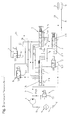
- a third step the pistons of the individual valves 8, 9, 12, 1, 2, 3 should continue to be in the position shown in FIG.
- the on / off valve 12 is closed.
- the piston 2.15 of the multiplex valve 2 is in the first position, as is the piston 3.19 of the safety valve 3 in the first position.
- the drive range selector lever position "Reverse" is selected.
- the piston 1.15 of the manual slide 1 is in the appropriate position.
- the hydraulic fluid system pressure p sys of the channel 17 is guided via the slots 1.4 and 1.3 to the channel 27 and thus to the input of the first coupling valve 8.
- the input of the second coupling valve 9 is guided via the channel 25, the fifth slot 2.5, the fourth slot 2.4 of the multiplex valve 2 on the channel 28 and from there via the slots 1.6 and 1.8 on the slot 1.7 of the manual slide 1, which with the open Container 1.26 is connected.
- At the entrance of the second clutch valve 9 is thus no system pressure p sys . Since the two clutches 10 and 11 are connected in the manner described above with the corresponding coupling valves 8 and 9, only one actuation of the first clutch 10 is possible in this valve position shown in Figure 3 by means of the first clutch valve 8.
- a fourth step the individual valves 8, 9, 12, 1, 2 and 3 are in the position shown in FIG. In particular, in turn, the on / off valve 12 is closed.
- the pistons 2.15 and 3.19 of the multiplex valve 2 and the safety valve 3 are again in position 1.
- the piston 1.15 of the manual valve 1 is now in the "parking" position.
- the hydraulic fluid system pressure p sys of the channel 17 is similar to the "neutral" position at the slots 1.4 and 2.3 of the manual valve 1 and the multiplex valve 2 and at the input of the on / off valve 12 at.
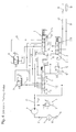
- pistons of the individual valves 8, 9, 12, 1, 2, 3 are in the positions shown in Figure 5.
- actuating piston be 1.15 of the manual valve 1 in the "reverse" position.
- the hydraulic fluid system pressure p sys the channel 17 is in accordance with the above description of Figure 3 at the entrance of the first clutch valve 8 at.
- valves 2, 3 and 12 in the illustrated in Figure 3 Position would be an operation of the first Coupling 10 not possible. An engagement of the reverse gear and thus a reversing of the motor vehicle would be locked out.
- This hydraulic fluid system pressure p sys now acts on the two end faces 2.16a and 3.11 of the respective pistons 2.15 and 3.19 of the multiplex valve 2 and the safety valve 3 and displaces these pistons 2.15 and 3.19 against the pressure of the respective actuation springs 2.14 and 3.10 into the respective details defined above second position.
- the output of the coupling valve 9 is now over the channel 24 and the slots 2.9 and 2.8 of the multiplex valve 2 with connected to the channel 21, which in turn to the second Slit 3.2 of the safety valve 3 is guided.
- a connection to one of the two clutches 10 or 11 does not exist, because the safety valve 3 now in the second position located.
- An actuation of the second coupling valve 9 So would not operate one of the two clutches 10, 11th trigger.
- the described position of the piston 3.19 of the safety valve 3 provides a connection between the first clutch 10 and the open container 3.18 via the channel 19 and the slots 3.3 and 3.4 and between the second clutch 11 and the open container 3.18 via the channel 20 and the Slots 3.6 and 3.7 ago.
- this position of the piston 3.19 the safety valve 3 so there is a complete emptying the clutches 10 and 11, without any actuation the couplings 10, 11 through one of the two coupling valves eighth and 9 would be possible.
- the hydraulic fluid system main pressure p sys of the channel 17 is at the third slot 2.3 of the multiplex valve 3, where he presses on the second face of the piston 2.15 2.16b and holds this against the force of the actuating spring in the second position 2.14.
- the output of the second clutch valve 9 is still over the channel 24 and the slots 2.9 and 2.8 with the channel 21st connected.
- the piston position of the safety valve 3 provides continue a connection of the channel 21 via the slots 3.2 and 3.3 to the channel 19 and thus to the first clutch 10 ago.
- By actuation of the second coupling valve 9 can be the first coupling 10 via channel 24, slot 2.9, slot 2.8, channel 21, slot 3.2, slot 3.3, channel 19 the second clutch 10 hydraulic actuate.
- the motor vehicle can thus also drive backwards.
Landscapes
- Engineering & Computer Science (AREA)
- General Engineering & Computer Science (AREA)
- Mechanical Engineering (AREA)
- Hydraulic Clutches, Magnetic Clutches, Fluid Clutches, And Fluid Joints (AREA)
Abstract
Description
Ansteuereinrichtung für hydraulisch betätigbare Kupplungen sowie Verfahren zur Ansteuerung hydraulisch betätigbarer Kupplungen.Control device for hydraulically actuated clutches and Method for controlling hydraulically actuated clutches.
Die Erfindung betrifft eine Ansteuereinrichtung für eine erste
und eine zweite hydraulisch betätigbare Kupplung eines Doppelkupplungsgetriebes
eines Kraftfahrzeugs gemäß dem Oberbegriff
des Patentanspruchs 1 sowie ein Verfahren zur Ansteuerung einer
ersten und einer zweiten hydraulisch betätigbaren Kupplung
eines Doppelkupplungsgetriebes eines Kraftfahrzeugs gemäß dem
Oberbegriff des Anspruchs 13.The invention relates to a drive device for a first
and a second hydraulically actuable clutch of a dual clutch transmission
of a motor vehicle according to the preamble
of
Aus dem betriebsintern bekannten Stand der Technik ist eine Ansteuereinrichtung für eine erste und zweite hydraulisch betätigbare Kupplung eines Doppelkupplungsgetriebes eines Kraftfahrzeugs bekannt. Diese weist zwei Kupplungsventile zum hydraulischen Betätigen der beiden Kupplung sowie einen Handschieber oder dergleichen auf.From the internally known state of the art is a Drive device for a first and second hydraulically actuated Clutch of a dual-clutch transmission of a motor vehicle known. This has two coupling valves for hydraulic Actuate the two clutch and a hand slider or the like.
Das erste Kupplungsventil zum hydraulischen Betätigen der ersten Kupplung liegt in einem ersten durch Kanäle gebildeten Hydraulikflüssigkeit führenden Pfad zu der ersten Kupplung und öffnet bzw. schließt diesen ersten Pfad zu der ersten Kupplung in Abhängigkeit von der jeweiligen Ventilstellung.The first coupling valve for hydraulically actuating the first Coupling lies in a first formed by channels Hydraulic fluid leading path to the first clutch and opens or closes this first path to the first clutch depending on the respective valve position.
In entsprechender Weise liegt das zum hydraulischen Betätigen der zweiten Kupplung vorgesehene zweite Kupplungsventil in einem zweiten durch Kanäle gebildeten Hydraulikflüssigkeit führenden Pfad zu der zweiten Kupplung. Auch dieses zweite Kupplungsventil ist in der Lage, diesen zweiten Pfad zu der zweiten Kupplung zu öffnen oder zu schließen. Correspondingly, this is for hydraulic actuation the second clutch provided second clutch valve in one second leading through channels formed hydraulic fluid Path to the second clutch. Also this second clutch valve is able to take this second path to the second Clutch to open or close.
Der Handschieber lässt in Abhängigkeit von einer Position eines Fahrbereichswählhebels, zum Beispiel Drive, Neutral, Reverse oder Parking, eine Betätigung der jeweiligen Kupplung aufgrund einer Betätigung des zugeordneten Kupplungsventils zu indem er die Hydraulikflüssigkeitskanäle zu den Kupplungen freigibt oder er unterbindet eine entsprechende Betätigung, indem er die Hydraulikflüssigkeitskanäle zu den Kupplungen schließt.The hand slider leaves depending on a position of a Drive range selector lever, for example Drive, Neutral, Reverse or Parking, an actuation of the respective clutch due to actuation of the associated clutch valve by bringing the hydraulic fluid channels to the couplings releases or prevents a corresponding actuation, by bringing the hydraulic fluid channels to the couplings closes.
Das in Abhängigkeit von einer Position des Fahrbereichswählhebels den ersten und/oder zweiten Pfade öffnende oder schließende Ventil kann durch die Wahl einer entsprechenden Position des Fahrbereichswählhebels - üblicherweise handelt es sich hierbei um die Reverse-Position - in eine Ventilstellung verbracht werden, in der der erste Pfad geöffnet und der zweite Pfad geschlossen ist.That depends on a position of the drive range selector lever the first and / or second paths opening or closing Valve can by choosing an appropriate position the range selector lever - usually it is here by the reverse position - spent in a valve position in which the first path is opened and the second Path is closed.
Fällt bei diesem Doppelkupplungsgetriebe ein Kupplungsventil aus, so kann im gewählten Beispiel das Kraftfahrzeug immer noch mit der verbleibenden Kupplung und einer eingeschränkten Anzahl Gänge gefahren werden. Dies gilt jedoch nicht für den Rückwärtsgang, den es nur einmal gibt.Falls in this dual-clutch transmission a clutch valve out, so in the example chosen, the motor vehicle always still with the remaining clutch and a limited one Number of courses to be driven. This does not apply to the Reverse, which exists only once.
Die Aufgabe der Erfindung liegt nunmehr darin, eine Ansteuereinrichtung für eine erste und eine zweite hydraulisch betätigbare Kupplung eines Doppelkupplungsgetriebes eine Kraftfahrzeugs der gattungsgemäßen Art derart auszubilden und weiterzubilden, dass stets ein Vorwärts- und Rückwärtsfahren möglich ist, auch wenn das eigentlich für einen entsprechenden Betrieb vorgesehene Kupplungsventil ausgefallen ist. Eine weitere Aufgabe der Erfindung liegt darin, ein entsprechendes Verfahren zur Ansteuerung einer ersten und einer zweiten hydraulisch betätigbaren Kupplung eines Doppelkupplungsgetriebes eines Kraftfahrzeugs der gattungsgemäßen Art vorzustellen, welches es ermöglicht, mit dem Kraftfahrzeug auch dann vorwärts und rückwärts fahren zu können, obwohl ein eigentlich für einen entsprechenden Betrieb vorgesehenes Kupplungsventil ausgefallen ist.The object of the invention is now a drive device for a first and a second hydraulically actuated Clutch of a dual-clutch transmission of a motor vehicle of the generic type in such a way and further educate, that always forward and backward driving possible is, even if that is actually for a corresponding Operation planned clutch valve has failed. Another The object of the invention is to provide a corresponding Method for controlling a first and a second hydraulically operable clutch of a dual-clutch transmission to present a motor vehicle of the generic type, which makes it possible with the motor vehicle then also forward and be able to drive backwards, although one actually intended for a corresponding operation clutch valve has failed.
Diese Aufgabe wird durch eine Ansteuereinrichtung mit den
Merkmalen des Patentanspruchs 1 sowie durch ein Verfahren mit
den Merkmalen des Patentanspruchs 13 erfindungsgemäß gelöst.This object is achieved by a drive with the
Features of
Vorteilhafte Ausführungen und Weiterbildungen der Erfindung sind in den Unteransprüchen angegeben.Advantageous embodiments and developments of the invention are given in the subclaims.
Bei einer Ansteuereinrichtung der gattungsgemäßen Art ist erfindungsgemäß ein Multiplexventil vorgesehen, welches bei Ausfall des ersten Kupplungsventils die Kanäle derart miteinander verbindet, dass das zweite Kupplungsventil in dem ersten Pfad liegt und diesen ersten Pfad öffnet oder schließt.In a control device of the generic type is according to the invention a multiplex valve provided, which in case of failure of the first coupling valve, the channels together connects that second clutch valve in the first path lies and opens or closes this first path.
Verfahrensmäßig wird diese Aufgabe dadurch gelöst, dass die Kanäle bei Ausfall des ersten Kupplungsventil derart miteinander verbunden werden, dass das zweite Kupplungsventil in dem ersten Pfad liegt und diesen ersten Pfad öffnet oder schließt.Procedurally, this object is achieved in that the Channels in case of failure of the first coupling valve with each other be connected, that the second clutch valve in the first path lies and opens or closes this first path.
In einer bevorzugten Ausführungsvariante ist weiter erfindungsgemäß vorgesehen, dass das Multiplexventil eine Selbsthalteeinrichtung aufweist. Diese Selbsthalteeinrichtung ist dazu vorgesehen, das Multiplexventil in der die Kanäle miteinander verbindenden Ventilstellung, in der das zweite Kupplungsventil in dem ersten Pfad liegt und diesen Pfad öffnet oder schließt zu halten. Das Multiplexventil braucht also nur aufgrund eines den Ausfall des ersten Kupplungsventils meldenden Signals in die entsprechende Ventilstellung verbracht werden, wo es selbstständig verbleibt.In a preferred embodiment variant is further according to the invention provided that the multiplex valve, a self-holding device having. This self-holding device is provided the multiplex valve in the channels with each other connecting valve position, in which the second coupling valve lies in the first path and opens this path or shut up. So the multiplex valve only needs due to a failure of the first clutch valve reporting Signals are spent in the appropriate valve position, where it remains independent.
In einer besonderen Ausgestaltung dieser Variante ist vorgesehen, dass die Selbsthalteeinrichtung nur dann wirksam ist, wenn der Druck der Hydraulikflüssigkeit einen vorgebbaren Schwellwert überschreitet. Durch diese Ausführungsvariante ist sichergestellt, dass ein Notbetrieb nur dann stattfindet, wenn ein ausreichender hydraulischer Druck, insbesondere der erforderliche Mindestdruck zum Betätigen der jeweiligen Kupplungen, vorhanden ist und eine unbeabsichtigte Betätigung ausgeschlossen ist.In a particular embodiment of this variant is provided that the self-holding device is only effective if the pressure of the hydraulic fluid is a predefinable Threshold exceeds. This variant is ensures that an emergency operation takes place only if a sufficient hydraulic pressure, in particular the required Minimum pressure for actuating the respective couplings, is present and precluded unintended operation is.
Vorzugsweise ist das Multiplexventil in der nachfolgend beschriebenen Art und Weise aufgebaut: Das Multiplexventil hat einen in einem wenigstens 13 Schlitze aufweisenden Steuergehäuse geführten Kolben mit fünf öffnenden und vier schließenden Kolbenabschnitten. Der Kolben ist dabei wahlweise in eine erste Position verbringbar, in welcher der erste öffnende Kolbenabschnitt nur den ersten Schlitz, der zweite öffnende Kolbenabschnitt den vierten und fünften Schlitz, der dritte öffnende Kolbenabschnitt den siebenten und achten Schlitz, der vierte öffnende Kolbenabschnitt den neunten und zehnten Schlitz und der fünfte öffnende Kolbenabschnitt den zwölften und dreizehnten Schlitz übergreift oder in eine zweite Position, in welcher der erste öffnende Kolbenabschnitt den zweiten und dritten Schlitz, der zweite öffnende Kolbenabschnitt den fünften und sechsten Schlitz, der dritte öffnende Kolbenabschnitt den achten und neunten Schlitz, der vierte öffnende Kolbenabschnitt den zehnten und elften Schlitz und der fünfte öffnende Kolbenabschnitt den dreizehnten Schlitz übergreift. Weiterhin ist der zweite Schlitz über einen Kanal mit dem zwölften Schlitz, der dritte Schlitz über einen Kanal mit einem Hydraulikflüssigkeitsbehälter mit Systemdruck verbunden. Der vierte Schlitz ist weiterhin in der ersten Fahrbereichswählhebelposition mit einem offenen Behälter, der fünfte Schlitz mit dem Eingang des zweiten Kupplungsventils, der sechste Schlitz mit dem Eingang des ersten Kupplungsventils, der siebente Schlitz mit dem Ausgang des ersten Kupplungsventils, der achte Schlitz mit dem zu der ersten Kupplung führenden Kanal, der neunte Schlitz mit dem Ausgang des zweiten Kupplungsventils, der zehnte Schlitz mit dem zu der zweiten Kupplung führenden Kanal und der elfte und dreizehnte Schlitz jeweils mit dem offenen Behälter verbunden.Preferably, the multiplexing valve is described below Fashion constructed: The multiplex valve has one in at least 13 slots having control housing guided pistons with five opening and four closing Piston sections. The piston is either in one first position can be brought, in which the first opening piston section only the first slot, the second opening piston section the fourth and fifth slot, the third opening Piston section the seventh and eighth slot, the fourth opening piston section the ninth and tenth Slot and the fifth opening piston section the twelfth and thirteenth slot overlaps or into a second position, in which the first opening piston section the second and third slot, the second opening piston section the fifth and sixth slot, the third opening piston section the eighth and ninth slot, the fourth opening Piston section the tenth and eleventh slot and the fifth opening piston section overlaps the thirteenth slot. Furthermore, the second slot via a channel with the twelfth slot, the third slot over a channel with one Hydraulic fluid reservoir connected to system pressure. The fourth slot is still in the first drive range selector position with an open container, the fifth Slot with the input of the second clutch valve, the sixth slot with the input of the first coupling valve, the seventh slot with the output of the first coupling valve, the eighth slot with the leading to the first clutch Channel, the ninth slot with the output of the second Clutch valve, the tenth slot with the second Clutch leading channel and the eleventh and thirteenth slot each connected to the open container.
Die Betätigung des Multiplexventils der vorstehend beschriebenen Ausführungsart erfolgt vorzugsweise dadurch, dass der erste Schlitz des Multiplexventils in der ersten Fahrbereichswählhebelposition mit dem Hydraulikflüssigkeitsbehälter mit Systemdruck verbindbar ist, welcher in verbundenem Zustand entgegen der Kraft einer Feder auf eine erste Stirnfläche des Kolbens wirkt und diesen dadurch in die zweite Position verbringt.The actuation of the multiplex valve of the above-described Embodiment preferably takes place in that the first Slot of the multiplex valve in the first drive range selector lever position with the hydraulic fluid container with System pressure is connectable, which in connected state against the force of a spring on a first end face of the Piston acts and this spends it in the second position.
In besonderer Ausgestaltung dieser Variante ist erfindungsgemäß ein Elektromagnetventil, vorzugsweise ein elektrisch betätigbares 3/2-Wege Ein-/Aus-Ventil, zum Verbinden des ersten Schlitzes des Multiplexventiles mit dem Hydraulikflüssigkeitsbehälter mit Systemdruck vorgesehen.In a special embodiment of this variant is according to the invention a solenoid valve, preferably an electrically actuated 3/2-way on / off valve, to connect the first Slot of the multiplex valve with the hydraulic fluid reservoir provided with system pressure.
Die Selbsthalteeinrichtung der vorstehend beschriebenen Art wird bei diesem zuletzt beschriebenen Multiplexventil vorzugsweise dadurch realisiert, dass der erste schließende Kolbenabschnitt eine zweite Stirnfläche aufweist. Der über den dritten Schlitz einspeisbare Systemdruck ist in der Lage, den Kolben entgegen der Kraft der vorstehend beschriebenen Feder in der zweiten vorstehend beschriebenen Position zu halten.The self-holding device of the type described above is preferred in this last-described multiplex valve realized in that the first closing piston section has a second end face. The over the third Slot injectable system pressure is capable of the piston against the force of the spring described above in the to hold the second position described above.
In besonderer Ausgestaltung der erfindungsgemäßen Ansteuereinrichtung kann ein Sicherheitsventil zum Entleeren der Kupplungen vorgesehen sein. Dieses Sicherheitsventil ermöglicht es, die Kupplungen in einen definierten Zustand zu verbringen, unabhängig davon, ob die entsprechenden Kupplungsventile ordnungsgemäß arbeiten oder nicht.In a particular embodiment of the drive device according to the invention can be a safety valve to drain the couplings be provided. This safety valve makes it possible to spend the clutches in a defined state, independently of whether the appropriate clutch valves are working properly work or not.
Das Sicherheitsventil ist vorzugsweise wie folgt ausgebildet: Es weist einen in einem Schlitze aufweisenden Steuergehäuse geführten Kolben mit zwei öffnenden und drei schließenden Kolbenabschnitten auf. Der Kolben ist wahlweise in eine erste Position verbringbar, in welcher der erste öffnende Kolbenabschnitt den zweiten und dritten Schlitz und der zweite öffnende Kolbenabschnitt den sechsten Schlitz übergreift oder - zum Drucklosschalten der Kupplungen - in eine zweite Position, in welcher der erste öffnende Kolbenabschnitt den dritten und vierten Schlitz und der zweite öffnende Kolbenabschnitt den siebenten und achten Schlitz übergreift.The safety valve is preferably designed as follows: It has an in-slots control housing guided piston with two opening and three closing piston sections on. The piston is optionally in a first position can be brought, in which the first opening piston section the second and third slots and the second opening slot Piston section overlaps the sixth slot or - to Depressurising the clutches - to a second position, in which the first opening piston section the third and fourth slot and the second opening piston section the seventh and eighth slot overlaps.
Hydraulisch ist dieses Sicherheitsventil wie folgt mit dem Multiplexventil und den entsprechenden Kupplungen verschaltet:Hydraulically, this safety valve is as follows with the Multiplex valve and the corresponding couplings interconnected:
Der zweite Schlitz ist über einen Kanal mit dem achten Schlitz des Multiplexventils, der dritte Schlitz ist über einen Kanal mit der ersten Kupplung, der vierte Schlitz ist über einen Kanal mit dem offenen Behälter, der fünfte Schlitz ist über einen Kanal mit dem zehnten Schlitz des Multiplexventils und der sechste Schlitz ist über einen Kanal mit dem offenen Behälter verbunden. Vorzugsweise ist wie beim vorstehend im Detail beschriebenen Multiplexventil der erste Schlitz des Sicherheitsventils mit dem Hydraulikflüssigkeitsbehälter oder mit Systemdruck verbindbar. Dieser Systemdruck wirkt im verbundenen Zustand entgegen der Kraft einer Feder auf eine Stirnfläche des Kolbens und verbringt diesen dadurch in die zweite Position.The second slot is over a channel with the eighth slot of the multiplex valve, the third slot is over a channel with the first clutch, the fourth slot is over a channel with the open container, the fifth slot is over one Channel with the tenth slot of the multiplex valve and the sixth slot is over a channel with the open tank connected. Preferably, as described in detail above Multiplex valve the first slot of the safety valve with the hydraulic fluid tank or system pressure can be connected. This system pressure counteracts in the connected state the force of a spring on an end face of the piston and thus spends it in the second position.
In einer besonders vorteilhaften Ausführungsvariante kann zum Verbinden des ersten Schlitzes des Sicherheitsventils mit Systemdruck ein Elektromagnetventil vorgesehen sein.In a particularly advantageous embodiment, the Connecting the first slot of the safety valve with system pressure a solenoid valve may be provided.
Zur Ansteuerung des Sicherheitsventils kann das Elektromagnetventil verwendet werden, das zur Ansteuerung des Multiplexventils dient.To control the safety valve, the solenoid valve used to control the multiplex valve serves.
Die Erfindung wird nunmehr mit Hilfe der Zeichnungen näher beschrieben. Es zeigen:
- Figur 1 :
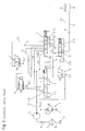
- Ein Ausführungsbeispiel einer Ansteuereinrichtung für eine erste und eine zweite hydraulisch betätigbare Kupplung eines Doppelkupplungsgetriebes eines Kraftfahrzeugs. Die Ansteuereinrichtung befindet sich im Normalbetriebszustand. Der Fahrbereichswählhebel befindet sich in der Position "Drive".
- Figur 2 :
- Die Ansteuereinrichtung gemäß der
Figur 1. Die Ansteuereinrichtung befindet sich im Normalbetriebszustand. Der Fahrbereichswählhebel befindet sich in der Position "Neutral". - Figur 3 :
- Die Ansteuereinrichtung gemäß den
Figuren 1 und 2. Die Ansteuereinrichtung befindet sich im Normalbetriebszustand. Der Fahrbereichswählhebel befindet sich in der Position "Reverse". - Figur 4 :
- Die Ansteuereinrichtung gemäß den
Figuren 1 bis 3. Die Ansteuereinrichtung befindet sich im Normalbetriebszustand. Der Fahrbereichswählhebel befindet sich in der Position "Parking". - Figur 5 :
- Die Ansteuereinrichtung gemäß den
Figuren 1 bis 4. Die Ansteuereinrichtung befindet sich im Fehlerbetriebszustand: Das erste Kupplungsventil ist ausgefallen. Der Fahrbereichswählhebel befindet sich in der Position "Reverse". Es folgt eine Umschaltung zum ersten Kupplungsventil auf das zweite Kupplungsventil. - Figur 6 :
- Die Ansteuereinrichtung gemäß den
Figuren 1 bis 5. Die Ansteuereinrichtung befindet sich im Fehlerbetriebszustand: Das erste Kupplungsventil ist ausgefallen. Der Fahrbereichswählhebel befindet sich in der Position "Reverse". Die in der Figur 5 beschriebene Umschaltung vom ersten Kupplungsventil auf das zweite Kupplungsventil 'ist abgeschlossen.
- FIG. 1:
- An embodiment of a drive device for a first and a second hydraulically actuated clutch of a dual-clutch transmission of a motor vehicle. The control device is in the normal operating state. The drive range selector lever is in the "Drive" position.
- FIG. 2:
- The drive device according to FIG. 1. The drive device is in the normal operating state. The drive range selector lever is in the "Neutral" position.
- FIG. 3:
- The drive device according to FIGS. 1 and 2. The drive device is in the normal operating state. The drive range selector lever is in the "Reverse" position.
- FIG. 4:
- The drive device according to FIGS. 1 to 3. The drive device is in the normal operating state. The drive range selector lever is in the "Parking" position.
- FIG. 5:
- The control device according to FIGS. 1 to 4. The control device is in the error operating state: the first clutch valve has failed. The drive range selector lever is in the "Reverse" position. This is followed by a switchover to the first coupling valve on the second coupling valve.
- FIG. 6:
- The control device according to FIGS. 1 to 5. The control device is in the error operating state: The first clutch valve has failed. The drive range selector lever is in the "Reverse" position. The switching from the first coupling valve to the second coupling valve 'described in FIG. 5 is completed.
Die Figuren 1 bis 6 zeigen in Form von Prinzipschaltbildern
ein Ausführungsbeispiel der erfindungsgemäßen Ansteuereinrichtung
für eine erste und eine zweite hydraulisch betätigbare
Kupplung 10, 11 eines Doppelkupplungsgetriebes eines Kraftfahrzeugs
in unterschiedlichen Betriebszuständen. Insbesondere
zeigen die Figuren 1 bis 4 die Ansteuereinrichtung bei Normalbetrieb.
Die Figuren 5 und 6 zeigen die Ansteuereinrichtung im
Fehlerfall, wenn ein zur Betätigung der ersten Kupplung 10
vorgesehenes erstes Kupplungsventil 8 aufgefallen ist.Figures 1 to 6 show in the form of schematic diagrams
An embodiment of the drive device according to the invention
for a first and a second hydraulically actuated
Um in der nachfolgenden Beschreibung eine einheitliche und einfache Bezugnahme zu gewährleisten, sind die in allen Figuren 1 bis 6 identisch vorliegenden Komponenten der beispielhaft skizzierten Ansteuereinrichtung mit einheitlichen Bezugszeichen versehen.In the following description a uniform and To ensure easy reference are the in all figures 1 to 6 identically present components of the example sketched drive with uniform reference numerals Provided.
Die Zeichnungsfiguren zeigen als wesentliche Komponenten der
erfindungsgemäßen Ansteuereinrichtung ein von einem Hydraulikflüssigkeitsbehälter
6 über eine Hydropumpe 4 gespeistes Hydraulikflüssigkeitskanalsystems,
deren einzelne Kanäle mit den
Bezugszeichen 15 bis 29 gekennzeichnet sind, ein elektromagnetisch
betätigbares Hauptdruckregelventil 7 zum Regeln des Systemdrucks
psys der von der Hydropumpe 4 bereitgestellten und
von einem Filter 5 gefilterten Hydraulikflüssigkeit, einen
Handschieber 1 zum Freigeben oder Unterbrechen des Hydraulikflüssigkeitsflusses
zu den beiden Kupplungen 10, 11 in Abhängigkeit
von der gewählten Position eines Fahrbereichswählhebels
für das Automatikgetriebe des Kraftfahrzeugs, zwei elektromagnetisch
betätigbare 3/2-Wege-Steuerventile 8, 9 (nachfolgend
als erstes und zweites Kupplungsventil bezeichnet) zum
Ansteuern der beiden Kupplungen 10 und 11 sowie ein Multiplexventil
2, ein Sicherheitsventil 3 und ein elektrisch betätigbares
3/2-Wege Ein-/Aus-Ventil 12, deren Aufbau und Funktion
nachfolgend im Detail beschrieben werden.The drawing figures show as essential components of the drive device according to the invention a fed by a hydraulic fluid reservoir 6 via a hydraulic pump 4 Hydraulikflüssigkeitskanalsystems whose individual channels are designated by the
Der Handschieber 1 ist in an sich bekannter Art ausgebildet.
Er umfasst ein im Wesentlichen zylinderförmiges Steuergehäuse
1.0, welches über dessen axialer Erstreckung 13 Schlitze 1.1,
1.2, 1.3, 1.4, 1.5, 1.6., 1.7, 1.8, 1.9, 1.10, 1.11, 1.12 und
1.13 aufweist. The
In diesem Steuergehäuse 1.0 ist in axialer Richtung ein Kolben 1.15 begrenzt verschieblich geführt. Die erste Stirnseite 1.16 des Kolbens 1.15 bildet einen einendseitigen Anschlag an einer Innenseite des Steuergehäuses 1.0. Anderenendseitig ist eine Betätigungsstange 1.14 vorgesehen, mit welcher sich der Kolben 1.15 in dem zylinderförmigen Steuergehäuse 1.0 in axialer Richtung verschieben lässt.In this control housing 1.0 is a piston in the axial direction 1.15 limited slidably guided. The first face 1.16 of the piston 1.15 forms a single end stop on one Inside of the control housing 1.0. The other end is one Operating rod 1.14 provided with which the piston 1.15 in the cylindrical control housing 1.0 in axial Move direction.
Der Kolben 1.15 weist längst seiner axialen Erstreckung unterschiedliche Durchmesser auf. Es gibt vier Kolbenabschnitte 1.17, 1.18, 1.19, 1.20, welche im Wesentlichen formschlüssig in der Innenwandung des Steuergehäuses 1.0 geführt sind. Fernerhin existieren drei Kolbenabschnitte 1.21, 1.22, 1.23, welche einen kleineren Aussendruchmesser aufweisen. Ein Kolbenabschnitt 1.21, 1.22, 1.23 der letztgenannten Art ist dabei jeweils in axialer Richtung benachbart zwischen zwei Kolbenabschnitten 1.17, 1.18., 1.19, 1.20 der erstgenannten Art angeordnet.The piston 1.15 has long since its axial extent different Diameter up. There are four piston sections 1.17, 1.18, 1.19, 1.20, which are substantially positive are guided in the inner wall of the control housing 1.0. henceforth There are three piston sections 1.21, 1.22, 1.23, which have a smaller outer diameter. A piston section 1.21, 1.22, 1.23 of the latter type is in each case in the axial direction adjacent between two piston sections 1.17, 1.18., 1.19, 1.20 of the former type arranged.
Erstreckt sich ein Kolbenabschnitt 1.21, 1.22, 1.23 der letztgenannten Art in einer bestimmten Stellung des Kolbens 1.15 in dem Steuergehäuse 1.0 von einem Schlitz 1.1, 1.2, 1.3, 1.4, 1.5, 1.6, 1.7, 1.8, 1.9, 1.10, 1.11, 1.12, 1.13 zu einem benachbarten Schlitz 1.1, 1.2, 1.3, 1.4, 1.5, 1.6, 1.7, 1.8. 1.9, 1.10, 1.11, 1.12, 1.13 so ist ein Durchfluss von Hydraulikflüssigkeit zwischen diesen beiden benachbarten Schlitzen 1.1, 1.2, 1.3, 1.4, 1.5, 1.6, 1.7, 1.8, 1.9, 1.10, 1.11, 1.12, 1.13 möglich. Kolbenabschnitte 1.21, 1.22, 1.23 der letztgenannten Art werden daher im folgenden als öffnende Kolbenabschnitte 1.21, 1.22, 1.23 bezeichnet, die anderen formschlüssig an der Innenwandung des Steuergehäuses 1.0 geführten Kolbenabschnitte 1.17, 1.18, 1.19, 1.20 werden nachfolgend als schließende Kolbenabschnitte 1.17, 1.18, 1.19, 1.20 bezeichnet, da hier kein Durchfluss von Hydraulikflüssigkeit zwischen benachbarten Schlitzen 1.1, 1.2, 1.3, 1.4, 1.5, 1.6, 1.7, 1.8, 1.9, 1.10, 1.11, 1.12, 1.13 möglich ist.Extends a piston portion 1.21, 1.22, 1.23 of the latter Type in a certain position of the piston 1.15 in the control housing 1.0 of a slot 1.1, 1.2, 1.3, 1.4, 1.5, 1.6, 1.7, 1.8, 1.9, 1.10, 1.11, 1.12, 1.13 to a neighboring one Slot 1.1, 1.2, 1.3, 1.4, 1.5, 1.6, 1.7, 1.8. 1.9, 1.10, 1.11, 1.12, 1.13 this is a flow of hydraulic fluid between these two adjacent slots 1.1, 1.2, 1.3, 1.4, 1.5, 1.6, 1.7, 1.8, 1.9, 1.10, 1.11, 1.12, 1.13 possible. Piston sections 1.21, 1.22, 1.23 of the latter Type are therefore hereinafter referred to as opening piston sections 1.21, 1.22, 1.23, the other form fit on the inner wall of the control housing 1.0 guided piston sections 1.17, 1.18, 1.19, 1.20 are hereafter referred to as closing piston sections 1.17, 1.18, 1.19, 1.20, there is no flow of hydraulic fluid between adjacent slots 1.1, 1.2, 1.3, 1.4, 1.5, 1.6, 1.7, 1.8, 1.9, 1.10, 1.11, 1.12, 1.13 is possible.
Der Kolben 1.15 des Handschiebers 1 ist im Ausführungsbeispiel
in vier unterschiedliche Stellungen verbringbar. In einer
Fahrbereichswählhebelposition "Drive" liegt die Stirnfläche
1.16 im vorliegenden Ausführungsbeispiel an der Endseite des
Steuergehäuses 1.0 an (positionsbestimmend ist dabei die Kolbenstangenposition
auf Grund der Wählhebelstellung). In dieser
"Drive"-Position übergreift der erste öffnende Kolbenabschnitt
1.21 den zweiten Schlitz 1.2 partiell. Der zweite öffnende
Kolbenabschnitt 1.22 übergreift den vierten, fünften und
sechsten Schlitz. Der dritte öffnende Kolbenabschnitt 1.23 übergreift
den neunten und zehnten Schlitz.The piston 1.15 of the
In der Wählhebelposition "Neutral" befindet sich der Kolben 1.15 in einer Stellung, in der der erste öffnende Kolbenabschnitt 1.21 den zweiten und dritten Schlitz 1.2, 1.3 der zweite öffnenden Kolbenabschnitt 1.22 den fünften, sechsten und teilweise den siebenten Schlitz 1.5, 1.6, 1.7 der dritte Kolbenabschnitt 1.23 teilweise den zehnten und den elften Schlitz 1.10, 1.11 vollständig übergreift.The selector lever position "Neutral" contains the piston 1.15 in a position in which the first opening piston section 1.21 the second and third slot 1.2, 1.3 of second opening piston section 1.22 the fifth, sixth and partly the seventh slot 1.5, 1.6, 1.7 the third Piston section 1.23 partly the tenth and the eleventh Slot 1.10, 1.11 completely overlaps.
Befindet sich der Fahrbereichswählhebel in der Position "Reverse" so übergreift der erste öffnende Kolbenabschnitt 1.21 die Schlitze 1.3 und 1.4 teilweise, der zweite öffnende Kolbenabschnitt 1.22 übergreift die Schlitze 1.6, 1.7 sowie teilweise den Kolbenabschnitt 1.8. Der dritte öffnende Kolbenabschnitt 1.23 übergreift den elften und zwölften Schlitz 1.11, 1.12. Ist die Fahrbereichswählhebelposition "Parking" angewählt, so befindet sich der Kolben 1.15 in einer Position, in der der erste öffnende Kolbenabschnitt 1.21 lediglich den fünften Schlitz 1.5, der zweite öffnende Kolbenabschnitt 1.22 die Kolbenabschnitte 1.7, 1.8 und 1.9 sowie der dritte öffnende Kolbenabschnitt 1.23 lediglich den dreizehnten Schlitz 1.13 übergreift.Is the drive range selector lever in the "Reverse" position so overlaps the first opening piston section 1.21 Slots 1.3 and 1.4 partially, the second opening piston section 1.22 overlaps the slots 1.6, 1.7 and partially the piston section 1.8. The third opening piston section 1.23 overlaps the eleventh and twelfth slots 1.11, 1.12. If the driving range selector lever position "Parking" is selected, then is the piston 1.15 in a position in which the first opening piston section 1.21 only the fifth Slot 1.5, the second opening piston section 1.22 the piston sections 1.7, 1.8 and 1.9 as well as the third opening piston section 1.23 only the thirteenth slot 1.13 overlaps.
Das Multiplexventil 2 ist wie folgt ausgebildet:The
Es umfasst ein im Wesentlichen zylinderförmiges Steuergehäuse 2.0, welches über dessen axialer Erstreckung 13 Schlitze, 2.1, 2.2, 2.3, 2.4, 2.5, 2.6, 2.7, 2.8, 2.9, 2.10, 2.11, 2.12, 2.13 aufweist.It comprises a substantially cylindrical control housing 2.0, which over its axial extent 13 slots, 2.1, 2.2, 2.3, 2.4, 2.5, 2.6, 2.7, 2.8, 2.9, 2.10, 2.11, 2.12, 2.13 having.
In diesem Steuergehäuse 2.0 ist in axialer Richtung ein Kolben 2.15 begrenzt verschieblich geführt. Die erste Stirnseite 2.16a des Kolbens 2.15 bildet einen einendseitigen Anschlag an einer Endseite des Steuergehäuses 2.0. An dem dieser Stirnseite 2.16a gegenüberliegenden Ende des Kolbens 2.15 ist stirnseitig eine Kolbenbetätigungsfeder 2.14 angeordnet, welche bei fehlender sonstiger Krafteinwirkung auf den Kolben 2.15 die erste Stirnseite 2.16a des Kolbens 2.15 gegen die eine Endseite des Steuergehäuses 1.0 gedrückt hält.In this control housing 2.0 is a piston in the axial direction 2.15 guided limited displacement. The first front page 2.16a of the piston 2.15 forms a single end stop one end side of the control housing 2.0. At this front 2.16a opposite end of the piston 2.15 is the front side arranged a piston actuating spring 2.14, which at lack of other force on the piston 2.15 the first end face 2.16a of the piston 2.15 against the one end side the control housing 1.0 holds pressed.
Der Kolben 2.15 weist entsprechend der vorstehenden Definition fünf öffnende und vier schließende Kolbenabschnitte 2.17, 2.18, 2.19, 2.20, 2.21, 2.22, 2.23, 2.24, 2.25 auf. Der erste schließende Kolbenabschnitt 2.17 bildet auf der der ersten Stirnseite 2.16a zugewandten Seite eine den öffnenden Kolbenabschnitt 2.21 ringförmig umschließende zweite Stirnfläche 2.16b, deren Aufgabe im nachfolgenden beschrieben wird. The piston 2.15 has according to the above definition five opening and four closing piston sections 2.17, 2.18, 2.19, 2.20, 2.21, 2.22, 2.23, 2.24, 2.25. The first closing piston section 2.17 forms on the first End face 2.16a facing a the opening piston portion 2.21 annularly enclosing second end face 2.16b, the task of which is described below.
Der Kolben 2.15 des Multiplexventils 2 ist wahlweise in eine
erste Position verbringbar, in welcher der erste öffnende Kolbenabschnitt
2.21 nur den ersten Schlitz 2.1, der zweite öffnende
Kolbenabschnitt 2.22 den vierten und fünften Schlitz
2.4, 2.5, der dritte öffnende Kolbenabschnitt 2.23 den siebenten
und achten Schlitz 2.7, 2.8, der vierte öffnende Kolbenabschnitt
2.24 den neunten und zehnten Schlitz 2.9, 2.10 und der
fünfte öffnende Kolbenabschnitt 2.25 den zwölften und dreizehnten
Schlitz 2.12, 2.13 übergreift oder in eine zweite Position,
in welcher der erste öffnende Kolbenabschnitt 2.21 den
zweiten und dritten Schlitz 2.2, 2.3, der zweite öffnende Kolbenabschnitt
2.22 den fünften und sechsten Schlitz 2.5, 2.6,
der dritte öffnende Kolbenabschnitt 2.23 den achten und neunten
Schlitz 2.8, 2.9, der vierte öffnende Kolbenabschnitt 2.24
den zehnten und elften Schlitz 2.10, 1.11 und der fünfte öffnende
Kolbenabschnitt 2.25 den dreizehnten Schlitz 2.13 übergreift.The piston 2.15 of the
Auch das Sicherheitsventil 3 ist in an sich bekannter Art ausgebildet.
Es umfasst ebenfalls ein im Wesentlichen zylinderförmiges
Steuergehäuse 3.0, welches über dessen axialer
Erstreckung neun Schlitze 3.1, 3.2, 3.3, 3.4, 3.5, 3.6, 3.7,
3.8, 3.9 aufweist.Also, the
In diesem Steuergehäuse 3.0 ist in axialer Richtung ein Kolben 2.19 begrenzt verschieblich geführt. Die erste Stirnseite 3.11 des Kolbens 3.19 bildet einen einendseitigen Anschlag an einer Endseite des Steuergehäuses 3.0. Zwischen der am gegenüberliegenden Ende des Kolbens 3.19 angeordneten Stirnseite und der anderen Endseite des Steuergehäuses 3.0 ist eine Kolbenbetätigungsfeder 3.10 angeordnet, welche bei fehlender sonstiger Krafteinwirkung auf den Kolben 3.19 die erste Stirnseite 3.11 des Kolbens 3.19 gegen die eine Endseite des Steuergehäuses 3.0 gedrückt hält.In this control housing 3.0 is a piston in the axial direction 2.19 limited slidably guided. The first face 3.11 of the piston 3.19 forms a single end stop on one End of the control housing 3.0. Between the one at the opposite End of the piston 3.19 arranged end face and the other end side of the control housing 3.0 is a piston actuating spring 3.10 arranged, which in the absence of others Force on the piston 3.19 the first face 3.11 of the piston 3.19 against the one end side of the control housing 3.0 holds.
Auch der Kolben 3.19 weist längs seiner axialen Erstreckung unterschiedliche Durchmesser auf. Es gibt drei schließende Kolbenabschnitte 3.12, 3.13, 3.14, welche im Wesentlichen formschlüssig in der Innenwandung des Steuergehäuses 3.0 geführt sind. Fernerhin gibt es benachbart zu diesen und zwischen diesen angeordnet zwei Kolbenabschnitte 3.15, 3.16, welche einen kleineren Außendurchmesser aufweisen, die öffnenden Kolbenabschnitte 3.15, 3.16.Also, the piston 3.19 has along its axial extent different diameters. There are three closing ones Piston sections 3.12, 3.13, 3.14, which substantially positively guided in the inner wall of the control housing 3.0 are. Furthermore, there are adjacent to these and between these arranged two piston sections 3.15, 3.16, which have a smaller outer diameter, the opening Piston sections 3.15, 3.16.
Der Kolben 3.19 ist wahlweise in eine erste Position verbringbar, in welcher der erste öffnende Kolbenabschnitt 3.15 den zweiten und dritten Schlitz 3.2, 3.3 und der zweite öffnende Kolbenabschnitt 3.16 den fünften und sechsten Schlitz 3.5 und 3.6 übergreift oder in eine zweite Position, in welcher der erste öffnende Kolbenabschnitt 3.15 den dritten und vierten Schlitz 3.3, 3.4 und der zweite öffnende Kolbenabschnitt 3.16 den sechsten und siebenten Schlitz 3.6 und 3.7 übergreift.The piston 3.19 can optionally be brought into a first position, in which the first opening piston section 3.15 the second and third slots 3.2, 3.3 and the second opening Piston section 3.16 the fifth and sixth slot 3.5 and 3.6 overlaps or in a second position in which the first opening piston section 3.15 the third and fourth Slot 3.3, 3.4 and the second opening piston section 3.16 the sixth and seventh slot 3.6 and 3.7 overlaps.
Die einzelnen vorstehend genannten bzw. beschriebenen Einzelbauteile der Ansteuereinrichtung sind über das vorstehend ebenfalls erwähnte Hydraulikflüssigkeitskanalsystem in nachfolgend beschriebener Weise miteinander verbunden:The individual above-mentioned or described individual components the driving device are above the above also mentioned hydraulic fluid channel system in the following as described:
Im Hydraulikflüssigkeitsbehälter 6 wird Hydraulikflüssigkeit
bereitgestellt. Von diesem Hydraulikflüssigkeitsbehälter 6
führt ein Kanal 15 zu einem Filter 5. Von dort führt ein Kanal
16 zur Hydropumpe 4, welche einen hydraulischen Druck im Leitungssystem
erzeugt. In the hydraulic fluid reservoir 6 is hydraulic fluid
provided. From this hydraulic fluid reservoir 6
a
Der Ausgang der Hydropumpe 4 mündet in den Kanal 17. An diesen
Kanal 17 ist das vorstehend genannte elektrisch betätigbare
Hauptdruckregelventil 7 angeschlossen, welches den Druck der
Hydraulikflüssigkeit im Kanal 17 durch Abgabe überschüssiger
Hydraulikflüssigkeit in einen offenen Behälter 7.1 auf den
Systemdruck psys regelt.The output of the hydraulic pump 4 opens into the
Der hydraulikflüssigkeitsführende Kanal 17 ist auf den vierten
Schlitz 1.4 des Handschiebers 1, den dritten Schlitz 2.3 des
Multiplexventils 2 sowie den Eingang des elektrisch betätigbaren
3/2-Wege Ein-/Aus-Ventils 12 geführt.The hydraulic fluid-carrying
Ein Kanal 27 verbindet die Schlitze 1.3 und 1.5 des Handschiebers
1 mit dem Eingang des ersten Kupplungsventils 8 und dem
sechsten Schlitz 2.6 des Multiplexventils 2. Ein Kanal 28 verbindet
die Schlitze 1.6 und 1.8 des Handschiebers 1 mit dem
vierten Schlitz 2.4 des Multiplexventils 2. Ein Kanal 29 verbindet
den neunten Schlitz 1.9, den elften Schlitz 1.11 und
den dreizehnten Schlitz 1.13 des Handschiebers 1 mit dem ersten
Schlitz 2.1 des Multiplexventils 2.A
Ein Kanal 26 verbindet den Ausgang des ersten Kupplungsventils
8 mit dem siebenten Schlitz 2.7 des Multiplexventils 2.A
Ein Kanal 25 verbindet den Eingang des zweiten Kupplungsventils
9 mit dem fünften Schlitz 2:5 des Multiplexventils 2.A
Ein Kanal 24 verbindet den Ausgang des zweiten Kupplungsventils
9 mit dem neunten Schlitz 2.9 des Multiplexventils 2.A
Weiterhin besteht über einen Kanal 18 eine Verbindung zwischen
dem Ausgang des Ein-/Aus-Ventils 12, dem Schlitz 1.12 des
Handschiebers 1 sowie dem ersten Schlitz 3.1 des Sicherheitsventils
3.Furthermore, there is a connection between a
Ein Kanal 21 verbindet die Schlitze 2.8 des Multiplexventils 2
und 3.2 des Sicherheitsventils 3. Ein Kanal 22 verbindet den
Schlitz 2.10 des Multiplexventils 2 mit dem Schlitz 3.6 des
Sicherheitsventils 3.A
Schließlich besteht eine Verbindung zwischen dem Schlitz 3.7
und der zweiten Kupplung 11 über den Kanal 20 sowie in entsprechender
Weise eine Verbindung zwischen dem Schlitz 3.3 und
der ersten Kupplung 10 über den Kanal 19.Finally, there is a connection between the slot 3.7
and the second clutch 11 via the
Die übrigen Schlitze 1.1, 1.2, 1.7, 1.10 des Handschiebers 1,
2.11 und 2.13 des Multiplexventils 2 und 3.4, 3.8 und 3.19 des
Sicherheitsventils 3 sowie die übrigen Eingänge der Kupplungsventile
8 und 9 sowie des Ein-/Aus-Ventils 12 sind mit einem
offenen Hydraulikflüssigkeitsbehälter 1.24, 1.25, 1.26 , 1.27,
2.25, 2.26, 3.18, 8.1, 9.1, 12.1 verbunden.The remaining slots 1.1, 1.2, 1.7, 1.10 of the
Weiterhin besteht eine Verbindung über den Kanal 23 zwischen
den Schlitzen 2.2 und 2.12 des Multiplexventils.Furthermore, there is a connection via the
Für die folgende Betrachtung wird nunmehr angenommen, dass ein Motor (z. B. ein Verbrennungsmotor oder ein Elektromotor) die Hydropumpe 4 antreibt, so dass an deren Pumpenaustritt und damit im Kanal 17 ein von dem Hauptdruckregelventil 7 geregelter im Wesentlichen konstanter Hydraulikflüssigkeitssystemdruck psys anliegt.For the following consideration, it is now assumed that an engine (eg an internal combustion engine or an electric motor) drives the hydraulic pump 4, so that at its pump outlet and thus in the passage 17 a substantially constant hydraulic fluid system pressure p sys controlled by the main pressure control valve 7 is present ,
Die Kolben der einzelnen Ventile 1, 8, 9, 2, 3, 12 sollen sich
zunächst in den in Figur 1 dargestellten Stellungen befinden.
Insbesondere befindet sich der Kolben 1.15 des Handschiebers 1
in der Position "Drive", der Kolben 2.15 des Multiplexventils
2 befindet sich in der ersten Position ebenso befindet sich
der Kolben 3.19 des Sicherheitsventils 3 in der ersten Position.
Das Ein-/Aus-Ventil 12 ist geschlossen. Der Hydraulikflüssigkeitssystemdruck
psys des Kanals 17 wird über den vierten
Schlitz 1.4 des Handschiebers 1 und den Kanal 27 auf den Eingang
des ersten Kupplungsventils abgeführt. Weiterhin wird der
Hydraulikflüssigkeitssystemdruck psys des Kanals 17 über den
fünften und sechsten Schlitz 1.5, 1.6 des Handschiebers 1, den
Kanal 28, den vierten und fünften Schlitz 2.4, 2.5 des Multiplexventils
auf den Eingang des zweiten Kupplungsventils 9 geführt.The pistons of the
Der Ausgang des ersten Kupplungsventils 8 ist über Kanal 26,
die Schlitze 2.7 und 2.8 des Multiplexventils 2, den Kanal 21,
die Schlitze 3.2 und 3.3 des Sicherheitsventils 3 und den Kanal
19 mit der ersten Kupplung 10 verbunden. In entsprechender
Weise ist der Ausgang des Kupplungsventils 9 über den Kanal
24, die Schlitze 2.9 und 2.10 des Multiplexventils 2, den Kanal
22, die Schlitze 3.5 und 3.6 des Sicherheitsventils 3 und
den Kanal 20 mit der zweiten Kupplung 11 verbunden.The output of the
Durch Betätigung der jeweiligen Kupplungsventile 8 und 9 können
in dem in Figur 1 dargestellten Zustand die Kupplungen 10
und 11 hydraulisch betätigt werden.By pressing the respective
Die Kolben der einzelnen Ventile 8, 9, 12, 1, 2, 3 sollen sich
nunmehr in der in der Figur 2 dargestellten Stellung befinden.
Insbesondere befindet sich der Kolben 1.15 des Handschiebers 1
in der Stellung "Neutral". Das Multiplexventil 2 und das Sicherheitsventil
3 befinden sich jeweils in der Position 1. Das
Ein-/Aus-Ventil 12 ist geschlossen. Der Hydraulikflüssigkeitssystemdruck
psys des Kanals 17 liegt an den Schlitzen 1.4 des
Handschiebers 1 und 2.3 des Multiplexventils 2 sowie am Eingang
des Ein-/Aus-Ventils 12 an.The pistons of the
Es besteht keine durchgehende Verbindung zu den Kupplungsventilen
8 und 9. Eine Betätigung der Kupplung über diese Kupplungsventile
8 und 9 ist also nicht möglich. In der in der Figur
2 dargestellten Ventilstellung der Kupplungsventile 8 und
9 werden die Kupplungen 10 und 11 über Kanal 19, Schlitz 3.3,
Schlitz 3.2, Kanal 21, Schlitz 2.8, Schlitz 2.7, Kanal 26 über
den offenen Behälter 8.1 sowie Kanal 20, Schlitz 3.6, Schlitz
3.5, Kanal 22, Schlitz 2.10, Schlitz 2.9, Kanal 24 und den offenen
Behälter 9.1 entleert.There is no continuous connection to the
In einem dritten Schritt sollen sich weiterhin die Kolben der
einzelnen Ventile 8, 9, 12, 1, 2, 3 in der in der Figur 3 dargestellten
Stellung befinden. Das Ein-/Aus-Ventil 12 ist geschlossen.
Der Kolben 2.15 des Multiplexventils 2 befindet
sich in der ersten Position, ebenso befindet sich der Kolben
3.19 des Sicherheitsventils 3 in der ersten Position. Es ist
die Fahrbereichswählhebelposition "Reverse" gewählt. Der Kolben
1.15 des Handschiebers 1 befindet sich in der entsprechenden
Stellung. Der Hydraulikflüssigkeitssystemdruck psys des Kanals
17 wird über die Schlitze 1.4 und 1.3 auf den Kanal 27
und damit auf den Eingang des ersten Kupplungsventils 8 geführt.
Der Eingang des zweiten Kupplungsventils 9 ist über den
Kanal 25, den fünften Schlitz 2.5, den vierten Schlitz 2.4 des
Multiplexventils 2 auf den Kanal 28 und von dort über die
Schlitze 1.6 und 1.8 auf den Schlitz 1.7 des Handschiebers 1
geführt, welcher mit dem offenen Behälter 1.26 verbunden ist.
Am Eingang des zweiten Kupplungsventils 9 liegt somit kein
Systemdruck psys an. Da die beiden Kupplungen 10 und 11 in der
vorstehend beschriebenen Weise mit den entsprechenden Kupplungsventilen
8 und 9 verbunden sind, ist in dieser in Figur 3
dargestellten Ventilstellung mittels des ersten Kupplungsventils
8 lediglich eine Betätigung der ersten Kupplung 10 möglich.In a third step, the pistons of the
In einem vierten Schritt seien die einzelnen Ventile 8, 9, 12,
1, 2 und 3 in der in Figur 4 dargestellten Stellung. Insbesondere
sei wiederum das Ein-/Aus-Ventil 12 geschlossen. Die Kolben
2.15 und 3.19 des Multiplexventils 2 und des Sicherheitsventils
3 seien wiederum in der Position 1. Der Kolben 1.15
des Handschiebers 1 befindet sich nunmehr in der "Parking"-Position.
Der Hydraulikflüssigkeitssystemdruck psys des Kanals
17 liegt ähnlich der "Neutral"-Stellung an den Schlitzen 1.4
bzw. 2.3 des Handschiebers 1 sowie des Multiplexventils 2 und
am Eingang des Ein-/Aus-Ventils 12 an.In a fourth step, the
Eine Betätigung der Kupplungen 10 und 11 mittels der Kupplungsventile
8 und 9 ist demzufolge wiederum nicht möglich.An actuation of the
Im Weiteren sollen sich die Kolben der einzelnen Ventile 8, 9,
12, 1, 2, 3 in den in Figur 5 dargestellten Stellungen befinden.
Insbesondere sei der Betätigungskolben 1.15 des Handschiebers
1 in der "Reverse"-Stellung.Furthermore, the pistons of the
Der Hydraulikflüssigkeitssystemdruck psys des Kanals 17 liegt
entsprechend der vorstehenden Beschreibung zur Figur 3 am Eingang
des ersten Kupplungsventils 8 an.The hydraulic fluid system pressure p sys the
Entgegen der vorstehenden Annahme sei nunmehr angenommen, dass
ein Fehlerfall vorliege und dass sich das erste Kupplungsventil
8 nicht mehr aus der in der Figur 5 dargestellten Stellung
nicht mehr verbringen lasse. Contrary to the above assumption, it is now assumed that
there is a fault and that the first
Würden sich die Ventile 2, 3 und 12 in der in der Figur 3 dargestellten
Stellung befinden, so wäre eine Betätigung der ersten
Kupplung 10 nicht möglich. Ein Einlegen des Rückwärtsganges
und damit ein Rückwärtsfahren des Kraftfahrzeugs wäre
ausgeschlossen.Would the
Es sei nunmehr angenommen, dass eine elektronische Steuereinrichtung
oder dergleichen diesen Fehlerzustand des ersten
Kupplungsventils 8 erkannt hat. Diese Steuereinrichtung sorgt
nunmehr dafür, dass sich das Ein-/Aus-Ventil 12 öffnet. In
dieser Folge wird der Hydraulikflüssigkeitssystemdruck psys des
Kanals 17 auf den Kanal 18 und damit einerseits über die
Schlitze 1.12 und 1.11 des Handschiebers 1 auf den Kanal 29
und damit auf den Schlitz 2.1 des Multiplexventils 2 und andererseits
auf den Schlitz 3.1 des Sicherheitsventils 3 geführt.It is now assumed that an electronic control device or the like has recognized this fault condition of the first
Dieser Hydraulikflüssigkeitssystemdruck psys wirkt nunmehr auf
die beiden Stirnflächen 2.16a und 3.11 der jeweiligen Kolben
2.15 und 3.19 des Multiplexventils 2 und des Sicherheitsventils
3 und verschiebt diese Kolben 2.15 und 3.19 entgegen dem
Druck der jeweiligen Betätigungsfedern 2.14 und 3.10 in die
jeweilige vorstehend im Detail definierte zweite Position.This hydraulic fluid system pressure p sys now acts on the two end faces 2.16a and 3.11 of the respective pistons 2.15 and 3.19 of the
Da sich nunmehr der Kolben 2.15 des Multiplexventils 2 in der
zweiten Position befindet, wird der Hydraulikflüssigkeitssystemdruck
psys des Kanals 17 über den vierten und dritten
Schlitz 1.4, 1.3 des Handschiebers 1 auf den Kanal 27 und von
dort weiter auf den sechsten und fünften Schlitz 2.6, 2.5 des
Multiplexventils 2 zum Kanal 25, welcher auf den Eingang des
zweiten Kupplungsventils 9 geführt ist. Demzufolge liegt nunmehr
der Hydraulikflüssigkeitssystemdruck psys am Eingang des
zweiten Kupplungsventils 9 an. Since now the piston 2.15 of the
Der Ausgang des Kupplungsventils 9 ist nunmehr über den Kanal
24 sowie die Schlitze 2.9 und 2.8 des Multiplexventils 2 mit
dem Kanal 21 verbunden, welcher wiederum auf den zweiten
Schlitz 3.2 des Sicherheitsventils 3 geführt ist. Eine Verbindung
zu einer der beiden Kupplungen 10 oder 11 besteht nicht,
da sich das Sicherheitsventil 3 nunmehr in der zweiten Position
befindet. Eine Betätigung des zweiten Kupplungsventils 9
würde also keine Betätigung einer der beiden Kupplungen 10, 11
auslösen.The output of the
Die beschriebene Stellung des Kolbens 3.19 des Sicherheitsventils
3 stellt jedoch eine Verbindung zwischen der ersten Kupplung
10 und dem offenen Behälter 3.18 über den Kanal 19 und
die Schlitze 3.3 und 3.4 sowie zwischen der zweiten Kupplung
11 und dem offenen Behälter 3.18 über den Kanal 20 und die
Schlitze 3.6 und 3.7 her. In dieser Stellung des Kolbens 3.19
des Sicherheitsventils 3 erfolgt also eine vollständige Entleerung
der Kupplungen 10 und 11, ohne dass eine Betätigung
der Kupplungen 10, 11 durch eine der beiden Kupplungsventile 8
und 9 möglich wäre.The described position of the piston 3.19 of the
Erfindungsgemäß ist daher vorgesehen, das Ein-/Aus-Ventil 12
nach erfolgter Entleerung der beiden Kupplungen 10 und 11 wieder
zu schließen, was der Figur 6 zu entnehmen ist. Dies hat
zur Folge, dass die zunächst entsprechend der Figur 5 unter
Hydraulikflüssigkeitssystemdruck psys stehende Hydraulikflüssigkeit,
welche die beiden Kolben 2.15, 3.19 der Ventile 2 und
3 in die zweite Position verbracht hat, über die jeweiligen
ersten Schlitze 2.1, 3.1 und die zugehörigen Kanäle 18 und 29
in den offenen Behälter 12.1 abfließen kann. Dadurch wird der
Kolben 3.19 des Sicherheitsventils 3 durch die Federkraft der
Kolbenbetätigungsfeder 3.10 in die Position 1 verbracht. Demgegenüber
steht der Hydraulikflüssigkeitssystemhauptdruck psys
des Kanals 17 am dritten Schlitz 2.3 des Multiplexventils 3
an, wo er auf die zweite Stirnfläche 2.16b des Kolbens 2.15
drückt und diesen entgegen der Kraft der Betätigungsfeder 2.14
in der zweiten Position hält.According to the invention, it is therefore provided to close the on / off
Der Ausgang des zweiten Kupplungsventils 9 ist weiterhin über
den Kanal 24 und die Schlitze 2.9 und 2.8 mit dem Kanal 21
verbunden. Die Kolbenstellung des Sicherheitsventils 3 stellt
weiterhin eine Verbindung des Kanals 21 über die Schlitze 3.2
und 3.3 zum Kanal 19 und damit zur ersten Kupplung 10 her.
Durch Betätigung des zweiten Kupplungsventils 9 läßt sich die
erste Kupplung 10 über Kanal 24, Schlitz 2.9, Schlitz 2.8, Kanal
21, Schlitz 3.2, Schlitz 3.3, Kanal 19 die zweite Kupplung
10 hydraulisch betätigen. Das Kraftfahrzeug kann somit auch
rückwärts fahren. The output of the second
- 11
- Handschiebermanual slide
- 1.01.0
- Steuergehäusecontrol housing
- 1.11.1
- Schlitzslot
- 1.21.2
- Schlitzslot
- 1.21.2
- Schlitzslot
- 1.41.4
- Schlitzslot
- 1.51.5
- Schlitzslot
- 1.61.6
- Schlitzslot
- 1.71.7
- Schlitzslot
- 1.81.8
- Schlitzslot
- 1.91.9
- Schlitzslot
- 1.101.10
- Schlitzslot
- 1.111.11
- Schlitzslot
- 1.121.12
- Schlitzslot
- 1.131.13
- Schlitzslot
- 1.141.14
- Betätigungsstangeactuating rod
- 1.151.15
- Kolbenpiston
- 1.161.16
- Stirnseite des KolbensFront side of the piston
- 1.171.17
- schließender Kolbenabschnittclosing piston section
- 1.181.18
- schließender Kolbenabschnittclosing piston section
- 1.191.19
- schließender Kolbenabschnittclosing piston section
- 1.201.20
- schließender Kolbenabschnittclosing piston section
- 1.211.21
- öffnender Kolbenabschnittopening piston section
- 1.221.22
- öffnender Kolbenabschnittopening piston section
- 1.231.23
- öffnender Kolbenabschnittopening piston section
- 1.241.24
- Offener BehälterOpen container
- 1.251.25
- offener Behälteropen container
- 1.261.26
- offener Behälteropen container
- 1.271.27
- offener Behälteropen container
- 22
- Multiplexventilmultiplex valve
- 2.02.0
- Steuergehäusecontrol housing
- 2.12.1
- Schlitzslot
- 2.22.2
- Schlitzslot
- 2.32.3
- Schlitzslot
- 2.42.4
- Schlitzslot
- 2.52.5
- Schlitzslot
- 2.62.6
- Schlitzslot
- 2.72.7
- Schlitzslot
- 2.82.8
- Schlitzslot
- 2.92.9
- Schlitzslot
- 2.102.10
- Schlitzslot
- 2.112.11
- Schlitzslot
- 2.122.12
- Schlitzslot
- 2.132.13
- Schlitzslot
- 2.142.14
- Betätigungsfederactuating spring
- 2.152.15
- Kolbenpiston
- 2.16a2.16a
- erste Stirnfläche des Kolbens 2.15first end face of the piston 2.15
- 2.16b2.16b
- zweite Stirnfläche des Kolbens 2.15second end face of the piston 2.15
- 2.162.16
- schließender Kolbenabschnittclosing piston section
- 2.172.17
- schließender Kolbenabschnittclosing piston section
- 2.182.18
- schließender Kolbenabschnittclosing piston section
- 2.192.19
- schließender Kolbenabschnittclosing piston section
- 2.202.20
- schließender Kolbenabschnittclosing piston section
- 2.212.21
- schließender Kolbenabschnittclosing piston section
- 2.222.22
- öffnender Kolbenabschnittopening piston section
- 2.232.23
- öffnender Kolbenabschnittopening piston section
- 2.242.24
- öffnender Kolbenabschnittopening piston section
- 2.252.25
- öffnender Kolbenabschnittopening piston section
- 2.262.26
- offener Behälteropen container
- 2.272.27
- offener Behälteropen container
- 33
- Sicherheitsventilsafety valve
- 3.03.0
- Steuergehäusecontrol housing
- 3.13.1
- Schlitzslot
- 3.23.2
- Schlitzslot
- 3.33.3
- Schlitzslot
- 3.43.4
- Schlitzslot
- 3.53.5
- Schlitzslot
- 3.63.6
- Schlitzslot
- 3.73.7
- Schlitzslot
- 3.83.8
- Schlitzslot
- 3.93.9
- Schlitzslot
- 3.103.10
- Betätigungsfederactuating spring
- 3.113.11
- Stirnseite des KolbensFront side of the piston
- 3.123.12
- schließender Kolbenabschnittclosing piston section
- 3.133.13
- schließender Kolbenabschnittclosing piston section
- 3.143.14
- schließender Kolbenabschnittclosing piston section
- 3.153.15
- öffnender Kolbenabschnittopening piston section
- 3.163.16
- öffnender Kolbenabschnittopening piston section
- 3.173.17
- offener Behälteropen container
- 3.183.18
- offener Behälteropen container
- 3.193.19
- Kolbenpiston
- 44
- Hydropumpehydraulic pump
- 55
- Filterfilter
- 66
- HydraulikflüssigkeitsbehälterHydraulic fluid reservoir
- 77
- HauptdruckregelventilMain pressure control valve
- 88th
- erstes Kupplungsventil (elektrisch betätigbares 3/2-WegeVentil)first coupling valve (electrically operated 3/2-way valve)
- 99
- zweites Kupplungsventil (elektrisch betätigbares 3/2-WegeVentil)second coupling valve (electrically operated 3/2-way valve)
- 1010
- erste Kupplungfirst clutch
- 1111
- zweite Kupplungsecond clutch
- 1212
- elektrisch betätigbares 3/2-Wege Ein-/Aus-Ventilelectrically operated 3/2-way on / off valve
Claims (14)
dadurch gekennzeichnet, dass das Multiplexventil (2) eine Selbsthalteeinrichtung (2,16a, 2.16b) aufweist, welche das Multiplexventil (2) in der die Kanäle (15, 16, 17, 27, 25, 24, 21, 19) miteinander verbindenden Ventilstellung hält, in der das zweite Kupplungsventil (9) in dem ersten Pfad liegt und diesen Pfad öffnet oder schließt.Drive device according to claim 1,
characterized in that the multiplex valve (2) comprises a self-retaining device (2, 16a, 2.16b) which interconnects the multiplex valve (2) in which the channels (15, 16, 17, 27, 25, 24, 21, 19) Valve position holds in which the second clutch valve (9) lies in the first path and opens or closes this path.
dadurch gekennzeichnet, dass die Selbsthalteeinrichtung (2.16a, 2.16b) nur dann wirksam ist, wenn der Druck der Hydraulikflüssigkeit einen vorgebbaren Schwellwert überschreitet.Drive device according to claim 2,
characterized in that the self-holding device (2.16a, 2.16b) is only effective when the pressure of the hydraulic fluid exceeds a predetermined threshold.
dadurch gekennzeichnet, dass das Multiplexventil (2) einen in einem wenigstens 13 Schlitze (2.1, 2.2, 2.3, 2.4, 2.5, 2.6, 2.7, 2.8, 2.9, 2.10, 2.11, 2.12, 2.13) aufweisenden Steuergehäuse (2.0) geführten Kolben (2.15) mit fünf öffnenden und vier schließenden Kolbenabschnitten (2.17, 2.18, 2.19, 2.20, 2.21, 2.22, 2.23, 2.24, 2.25) aufweist, wobei der Kolben (2.15) wahlweise in eine erste Position verbringbar ist, in welcher der erste öffnende Kolbenabschnitt (2.21) nur den ersten Schlitz (2.1), der zweite öffnende Kolbenabschnitt (2.22) den vierten und fünften Schlitz (2.4, 2.5), der dritte öffnende Kolbenabschnitt (2.23) den siebenten und achten Schlitz (2.7, 2.8), der vierte öffnende Kolbenabschnitt (2.24) den neunten und zehnten Schlitz (2.9, 2.10) und der fünfte öffnende Kolbenabschnitt (2.25) den zwölften und dreizehnten Schlitz (2.12, 2.13) übergreift oder in eine zweite Position, in welcher der erste öffnende Kolbenabschnitt (2.21) den zweiten und dritten Schlitz (2.2, 2.3), der zweite öffnende Kolbenabschnitt (2.22) den fünften und sechsten Schlitz (2.5, 2.6) der dritte öffnende Kolbenabschnitt (2.23) den achten und neunten Schlitz (2.8, 2.9), der vierte öffnende Kolbenabschnitt (2.24) den zehnten und elften Schlitz (2.10, 2.11) und der fünfte öffnende Kolbenabschnitt (2.25) den dreizehnten Schlitz (2.13) übergreift und wobei der zweite Schlitz (2.2) über einen Kanal (23) mit dem zwölften Schlitz (2.12), der dritte Schlitz (2.3) über einen Kanal (17) mit einem Hydraulikflüssigkeitsbehälter (6) mit Systemdruck (psys), der vierte Schlitz (2.4) in der ersten Fahrbereichswählhebelposition (Reverse) mit einem offenen Behälter (1.26) der fünfte Schlitz (2.5) mit dem Eingang des zweiten Kupplungsventils (9) der sechste Schlitz (2.6) mit dem Eingang des ersten Kupplungsventils (8), der siebente Schlitz (7) mit dem Ausgang des ersten Kupplungsventil (8) der achte Schlitz (2.8) mit dem zu der ersten Kupplung (10) führenden Kanal (21,19) der neunte Schlitz (2.9) mit dem Ausgang des zweiten Kupplungsventils (9) der zehnte Schlitz (2.10) mit dem zu der zweiten Kupplung (11) führenden Kanal (22, 20), der elfte Schlitz (2.11) mit dem offenen Behälter (2.25) und der dreizehnte Schlitz (2.13) mit dem offenen Behälter (2.26) verbunden ist.Drive device according to one of claims 1 to 3,
characterized in that the multiplex valve (2) has a piston guided in an at least 13 slots (2.1, 2.2, 2.3, 2.4, 2.5, 2.6, 2.7, 2.8, 2.9, 2.10, 2.11, 2.12, 2.13) ( 2.15) having five opening and four closing piston sections (2.17, 2.18, 2.19, 2.20, 2.21, 2.22, 2.23, 2.24, 2.25), wherein the piston (2.15) is selectively engageable in a first position in which the first opening piston section (2.21) only the first slot (2.1), the second opening piston section (2.22) the fourth and fifth slots (2.4, 2.5), the third opening piston section (2.23) the seventh and eighth slots (2.7, 2.8), the fourth opening Piston portion (2.24) the ninth and tenth slot (2.9, 2.10) and the fifth opening piston portion (2.25) the twelfth and thirteenth slot (2.12, 2.13) overlaps or in a second position, in which the first opening piston portion (2.21) the second and third slot ( 2.2, 2.3), the second opening piston section (2.22) the fifth and sixth slot (2.5, 2.6) the third opening piston section (2.23) the eighth and ninth slot (2.8, 2.9), the fourth opening piston section (2.24) the tenth and eleventh slot (2.10, 2.11) and the fifth opening piston section (2.25) overlaps the thirteenth slot (2.13) and wherein the second slot (2.2) via a channel (23) with the twelfth slot (2.12), the third slot (2.3) via a channel (17) with a hydraulic fluid reservoir (6) with system pressure (p sys ), the fourth slot (2.4) in the first driving range selector lever position (reverse) with an open container (1.26) the fifth slot (2.5) with the input of the second Clutch valve (9) the sixth slot (2.6) with the input of the first clutch valve (8), the seventh slot (7) with the output of the first clutch valve (8) the eighth slot (2.8) with the first clutch (10) leading channel (21,19) the ninth slot (2.9) with the outlet of the second coupling valve (9) the tenth slot (2.10) with the channel (22, 20) leading to the second coupling (11), the eleventh slot (2.11) with the open container (2.25 ) and the thirteenth slot (2.13) is connected to the open container (2.26).
dadurch gekennzeichnet, dass der erste Schlitz (2.1) des Multiplexventils (2) in der ersten Fahrbereichswählhebelposition (Reverse) mit dem Hydraulikflüssigkeitsbehälter (6) mit Systemdruck (psys) verbindbar ist, welcher im verbunden Zustand entgegen der Kraft einer Feder (2.14) auf eine erste Stirnfläche (2.16a) des Kolbens (2.15), diesen in die zweite Position verbringend wirkt.Drive device according to one of claims 2 to 4,
characterized in that the first slot (2.1) of the multiplex valve (2) in the first Fahrbereichswählhebelposition (reverse) with the hydraulic fluid reservoir (6) with system pressure (p sys ) is connected, which in the connected state against the force of a spring (2.14) on a first end face (2.16a) of the piston (2.15), this acts in the second position.
dadurch gekennzeichnet, dass ein Elektromagnetventil (12) zum Verbinden des ersten Schlitzes (2.1) des Multiplexventils (2) mit dem Hydraulikflüssigkeitsbehälter (6) mit Systemdruck (psys) vorgesehen ist.Drive device according to claim 5,
characterized in that a solenoid valve (12) for connecting the first slot (2.1) of the multiplex valve (2) with the hydraulic fluid reservoir (6) with system pressure (p sys ) is provided.
dadurch gekennzeichnet, dass das Sicherheitsventil (3) einen in einem acht Schlitze (3.1, 3.2, 3.3, 3.4, 3.5, 3.6, 3.7, 3.8) aufweisenden Steuergehäuse (3.0) geführten Kolben (3.19) mit zwei öffnenden und drei schließenden Kolbenabschnitten (3.12, 3.13, 3.14, 3.15, 3.16) aufweist, wobei der Kolben (3.19) wahlweise in eine erste Position verbringbar ist, in welcher der erste öffnende Kolbenabschnitt (3.15) den zweiten und dritten Schlitz (3.2, 3.3) und der zweite öffnende Kolbenabschnitt (3.16) den sechsten Schlitz (3.6) übergreift oder in eine zweite Position zum Drucklosschalten der Kupplung, in welcher der erste öffnende Kolbenabschnitt (3.15) den dritten und vierten Schlitz (3.3, 3.4) und der zweite öffnende Kolbenabschnitt (3.16) den siebenten und achten Schlitz (3.7, 3.8) übergreift, wobei der zweite Schlitz (3.2) über einen Kanal (21) mit dem achten Schlitz (2.8) des Multiplexventils (2), der dritte Schlitz (3.2) über einen Kanal (19) mit der ersten Kupplung (10), der vierte Schlitz (3.4) über einen Kanal mit dem offenen Behälter (3.18), der fünfte Schlitz (3.5) über ein Kanal (22) mit dem zehnten Schlitz (2.10) des Multiplexventils (2) und der sechste Schlitz (3.6) über einen Kanal mit dem offenen Behälter (3.18) verbunden ist.Drive device according to claim 8,
characterized in that the safety valve (3) in one eight slots (3.1, 3.2, 3.3, 3.4, 3.5, 3.6, 3.7, 3.8) having control housing (3.0) guided piston (3.19) with two opening and three closing piston sections (3.12 , 3.13, 3.14, 3.15, 3.16), wherein the piston (3.19) is selectively movable into a first position, in which the first opening piston portion (3.15) the second and third slot (3.2, 3.3) and the second opening piston portion ( 3.16) overlaps the sixth slot (3.6) or into a second position for depressurizing the clutch, in which the first opening piston portion (3.15) the third and fourth slot (3.3, 3.4) and the second opening piston portion (3.16) the seventh and eighth Slit (3.7, 3.8) overlaps, wherein the second slot (3.2) via a channel (21) with the eighth slot (2.8) of the multiplex valve (2), the third slot (3.2) via a channel (19) with the first coupling (10), the fourth slot (3.4) via a channel with the open container (3.18), the fifth slot (3.5) via a channel (22) with the tenth slot (2.10) of the multiplex valve (2) and the sixth slot (3.6) via a channel connected to the open container (3.18).
dadurch gekennzeichnet, dass der erste Schlitz (3.1) des Sicherheitsventils (3) mit dem Hyd-raulikflüssigkeitsbehälter (2.1) oder mit Systemdruck (psys) verbindbar ist, welcher im verbundenen Zustand entgegen der Kraft einer Feder (3.9) auf eine Stirnfläche (3.11) des Kolbens (3.19), diesen in die zweite Position verbringend, wirkt.Drive device according to claim 9,
characterized in that the first slot (3.1) of the safety valve (3) can be connected to the hydraulic fluid reservoir (2.1) or to system pressure (p sys ) which, in the connected state, counteracts the force of a spring (3.9) on an end face (3.11 ) of the piston (3.19), putting it in the second position.
dadurch gekennzeichnet, dass ein Elektromagnetventil (12) zum Verbinden des ersten Schlitzes (3.1) des Sicherheitsventils (3) mit Systemdruck (psys) oder einem anderen vorgebbaren von Null verschiedenen Druck vorgesehen ist.Drive device according to claim 10,
characterized in that a solenoid valve (12) for connecting the first slot (3.1) of the safety valve (3) with system pressure (p sys ) or another predetermined non-zero pressure is provided.
dadurch gekennzeichnet,dass das Elektromagnetventil (12) sowohl zum Verbinden des ersten Schlitzes (3.1) des Sicherheitsventils (3) als auch zum Verbinden des ersten Schlitzes (2.1) des Multiplexventils (2) mit dem Hydraulikflüssigkeitsbehälter (6) mit Systemdruck (psys) vorgesehen ist.Drive device according to claim 11,
characterized in that the solenoid valve (12) both for connecting the first slot (3.1) of the safety valve (3) and for connecting the first slot (2.1) of the multiplex valve (2) with the hydraulic fluid reservoir (6) with system pressure (p sys ) is provided.
dadurch gekennzeichnet,dass die Kupplungen (10,11) vor dem Verbinden vollständig entleert werden.Method according to claim 13,
characterized in that the couplings (10,11) are completely emptied before connecting.
Priority Applications (2)
| Application Number | Priority Date | Filing Date | Title |
|---|---|---|---|
| DE50308178T DE50308178D1 (en) | 2003-09-29 | 2003-09-29 | Control device for hydraulically actuated clutches and method for controlling hydraulically actuated clutches |
| EP20030021911 EP1519082B1 (en) | 2003-09-29 | 2003-09-29 | Control device and method for hydraulically operated clutches |
Applications Claiming Priority (1)
| Application Number | Priority Date | Filing Date | Title |
|---|---|---|---|
| EP20030021911 EP1519082B1 (en) | 2003-09-29 | 2003-09-29 | Control device and method for hydraulically operated clutches |
Publications (2)
| Publication Number | Publication Date |
|---|---|
| EP1519082A1 true EP1519082A1 (en) | 2005-03-30 |
| EP1519082B1 EP1519082B1 (en) | 2007-09-12 |
Family
ID=34178519
Family Applications (1)
| Application Number | Title | Priority Date | Filing Date |
|---|---|---|---|
| EP20030021911 Expired - Lifetime EP1519082B1 (en) | 2003-09-29 | 2003-09-29 | Control device and method for hydraulically operated clutches |
Country Status (2)
| Country | Link |
|---|---|
| EP (1) | EP1519082B1 (en) |
| DE (1) | DE50308178D1 (en) |
Cited By (27)
| Publication number | Priority date | Publication date | Assignee | Title |
|---|---|---|---|---|
| DE102006054253A1 (en) * | 2006-11-17 | 2008-05-21 | Zf Friedrichshafen Ag | Method for emergency operation of an automated vehicle dual-clutch transmission |
| EP1950463A1 (en) * | 2007-01-23 | 2008-07-30 | Getrag Ford Transmissions GmbH | Hydraulic control device for automated double clutch transmission |
| US8192176B2 (en) | 2009-12-10 | 2012-06-05 | GM Global Technology Operations LLC | Hydraulic fluid supply system having active regulator |
| US8225687B2 (en) | 2009-09-09 | 2012-07-24 | GM Global Technology Operations LLC | Hydraulic control systems for dual clutch transmissions |
| US8403792B2 (en) | 2009-10-21 | 2013-03-26 | GM Global Technology Operations LLC | Hydraulic control systems for dual clutch transmissions |
| US8402855B2 (en) | 2010-01-11 | 2013-03-26 | GM Global Technology Operations LLC | Hydraulic control systems for dual clutch transmissions |
| US8403793B2 (en) | 2010-02-17 | 2013-03-26 | GM Global Technology Operations LLC | Hydraulic control system for an automatic transmission having a lubrication regulation valve |
| US8413777B2 (en) | 2010-02-17 | 2013-04-09 | GM Global Technology Operations LLC | High efficiency hydraulic transmission control system |
| US8413437B2 (en) | 2009-12-08 | 2013-04-09 | GM Global Technology Operations LLC | Transmission hydraulic control system having independently controlled stator cooling flow |
| US8429994B2 (en) | 2009-09-09 | 2013-04-30 | GM Global Technology Operations LLC | Hydraulic control systems for dual clutch transmissions |
| US8434381B2 (en) | 2009-08-28 | 2013-05-07 | GM Global Technology Operations LLC | Transmission for a motor vehicle |
| US8435148B2 (en) | 2010-01-11 | 2013-05-07 | GM Global Technology Operations LLC | Hydraulic control system for an automatic transmission having electronic transmission range selection with failure mode control |
| US8443687B2 (en) | 2009-12-14 | 2013-05-21 | GM Global Technology Operations LLC | Electro-hydraulic control system for a dual clutch transmission |
| US8475336B2 (en) | 2009-07-30 | 2013-07-02 | GM Global Technology Operations LLC | Hydraulic control system for a dual clutch transmission |
| US8500600B2 (en) | 2011-01-10 | 2013-08-06 | GM Global Technology Operations LLC | Hydraulic control system for an automatic transmission having a manual valve with a two gear default strategy |
| US8567580B2 (en) | 2010-01-22 | 2013-10-29 | GM Global Technology Operations LLC | Electro-hydraulic control system for a dual clutch transmission |
| US8579094B2 (en) | 2010-01-11 | 2013-11-12 | GM Global Technology Operations LLC | Hydraulic control system for an automatic transmission having a three path torque converter control subsystem |
| US8702548B2 (en) | 2011-11-03 | 2014-04-22 | Gm Global Technology Operations | Hydraulic control system for an automatic transmission |
| US8733521B2 (en) | 2010-12-06 | 2014-05-27 | Gm Global Technology Operations | Apparatus for and method of controlling a dual clutch transmission |
| US8738257B2 (en) | 2010-12-08 | 2014-05-27 | Gm Global Technology Operations, Llc | Electro-hydraulic control system and method for a dual clutch transmission |
| US8740748B2 (en) | 2010-12-08 | 2014-06-03 | Gm Global Technology Operations, Llc | Control system and method for a dual clutch transmission |
| US8839928B2 (en) | 2010-12-02 | 2014-09-23 | Gm Global Technology Operations, Llc | Electro-hydraulic control system for a dual clutch transmission |
| US8904893B2 (en) | 2010-12-06 | 2014-12-09 | Gm Global Technology Operations, Llc | Method of controlling a dual clutch transmission |
| US8915076B2 (en) | 2011-01-12 | 2014-12-23 | Gm Global Technology Operations, Llc | Transmission hydraulic control system having flow augmentation |
| US8942901B2 (en) | 2010-12-09 | 2015-01-27 | Gm Global Technology Operations, Llc | Method of controlling a hydraulic control system for a dual clutch transmission |
| US9080666B2 (en) | 2012-05-29 | 2015-07-14 | Gm Global Technology Operations, Inc. | Discrete mechanism for electronic transmission range selection |
| US10167948B2 (en) | 2016-03-17 | 2019-01-01 | GM Global Technology Operations LLC | Hydraulic control system for an automatic transmission |
Citations (7)
| Publication number | Priority date | Publication date | Assignee | Title |
|---|---|---|---|---|
| US5383379A (en) * | 1991-06-07 | 1995-01-24 | Honda Giken Kogyo Kabushiki Kaisha | Hydraulic pressure control for automatic transmission |
| EP0803663A1 (en) * | 1996-04-16 | 1997-10-29 | Toyota Jidosha Kabushiki Kaisha | Hydraulic control system for automatic transmission of multiple clutch type |
| US5816977A (en) * | 1996-05-27 | 1998-10-06 | Toyota Jidosha Kabushiki Kaisha | Oil pressure control system having an ON/OFF solenoid and a lowered electrical resistance pwm solenoid for controlling a pressure regulator |
| US5919108A (en) * | 1996-10-23 | 1999-07-06 | Aisin Seiki Kabushiki Kaisha | Hydraulic control apparatus for automatic transmission |
| EP0947742A2 (en) * | 1998-03-30 | 1999-10-06 | Mazda Motor Corporation | Apparatus for controlling automatic transmission |
| US6527670B1 (en) * | 1998-12-18 | 2003-03-04 | Zf Friedrichshafen Ag | Control device for an automatic automobile transmission |
| US20030083169A1 (en) * | 2001-10-11 | 2003-05-01 | Akihito Iwata | Hydraulic pressure controller for automatic transmission |
-
2003
- 2003-09-29 DE DE50308178T patent/DE50308178D1/en not_active Expired - Lifetime
- 2003-09-29 EP EP20030021911 patent/EP1519082B1/en not_active Expired - Lifetime
Patent Citations (7)
| Publication number | Priority date | Publication date | Assignee | Title |
|---|---|---|---|---|
| US5383379A (en) * | 1991-06-07 | 1995-01-24 | Honda Giken Kogyo Kabushiki Kaisha | Hydraulic pressure control for automatic transmission |
| EP0803663A1 (en) * | 1996-04-16 | 1997-10-29 | Toyota Jidosha Kabushiki Kaisha | Hydraulic control system for automatic transmission of multiple clutch type |
| US5816977A (en) * | 1996-05-27 | 1998-10-06 | Toyota Jidosha Kabushiki Kaisha | Oil pressure control system having an ON/OFF solenoid and a lowered electrical resistance pwm solenoid for controlling a pressure regulator |
| US5919108A (en) * | 1996-10-23 | 1999-07-06 | Aisin Seiki Kabushiki Kaisha | Hydraulic control apparatus for automatic transmission |
| EP0947742A2 (en) * | 1998-03-30 | 1999-10-06 | Mazda Motor Corporation | Apparatus for controlling automatic transmission |
| US6527670B1 (en) * | 1998-12-18 | 2003-03-04 | Zf Friedrichshafen Ag | Control device for an automatic automobile transmission |
| US20030083169A1 (en) * | 2001-10-11 | 2003-05-01 | Akihito Iwata | Hydraulic pressure controller for automatic transmission |
Cited By (31)
| Publication number | Priority date | Publication date | Assignee | Title |
|---|---|---|---|---|
| US8086381B2 (en) | 2006-11-17 | 2011-12-27 | Zf Friedrichshafen Ag | Method for the emergency actuation of an automated double clutch transmission of a motor vehicle |
| WO2008058857A1 (en) * | 2006-11-17 | 2008-05-22 | Zf Friedrichshafen Ag | Method for the emergency actuation of an automated double clutch transmission of a motor vehicle |
| DE102006054253A1 (en) * | 2006-11-17 | 2008-05-21 | Zf Friedrichshafen Ag | Method for emergency operation of an automated vehicle dual-clutch transmission |
| CN101255921B (en) * | 2007-01-23 | 2013-02-13 | 各特拉格·福特传动系统公司 | Hydraulic control device for automated double clutch transmission |
| EP1950463A1 (en) * | 2007-01-23 | 2008-07-30 | Getrag Ford Transmissions GmbH | Hydraulic control device for automated double clutch transmission |
| US8475336B2 (en) | 2009-07-30 | 2013-07-02 | GM Global Technology Operations LLC | Hydraulic control system for a dual clutch transmission |
| US8434381B2 (en) | 2009-08-28 | 2013-05-07 | GM Global Technology Operations LLC | Transmission for a motor vehicle |
| US8225687B2 (en) | 2009-09-09 | 2012-07-24 | GM Global Technology Operations LLC | Hydraulic control systems for dual clutch transmissions |
| US8429994B2 (en) | 2009-09-09 | 2013-04-30 | GM Global Technology Operations LLC | Hydraulic control systems for dual clutch transmissions |
| US8403792B2 (en) | 2009-10-21 | 2013-03-26 | GM Global Technology Operations LLC | Hydraulic control systems for dual clutch transmissions |
| US8413437B2 (en) | 2009-12-08 | 2013-04-09 | GM Global Technology Operations LLC | Transmission hydraulic control system having independently controlled stator cooling flow |
| US8192176B2 (en) | 2009-12-10 | 2012-06-05 | GM Global Technology Operations LLC | Hydraulic fluid supply system having active regulator |
| US8443687B2 (en) | 2009-12-14 | 2013-05-21 | GM Global Technology Operations LLC | Electro-hydraulic control system for a dual clutch transmission |
| US8435148B2 (en) | 2010-01-11 | 2013-05-07 | GM Global Technology Operations LLC | Hydraulic control system for an automatic transmission having electronic transmission range selection with failure mode control |
| US8402855B2 (en) | 2010-01-11 | 2013-03-26 | GM Global Technology Operations LLC | Hydraulic control systems for dual clutch transmissions |
| US8579094B2 (en) | 2010-01-11 | 2013-11-12 | GM Global Technology Operations LLC | Hydraulic control system for an automatic transmission having a three path torque converter control subsystem |
| US8567580B2 (en) | 2010-01-22 | 2013-10-29 | GM Global Technology Operations LLC | Electro-hydraulic control system for a dual clutch transmission |
| US8413777B2 (en) | 2010-02-17 | 2013-04-09 | GM Global Technology Operations LLC | High efficiency hydraulic transmission control system |
| US8403793B2 (en) | 2010-02-17 | 2013-03-26 | GM Global Technology Operations LLC | Hydraulic control system for an automatic transmission having a lubrication regulation valve |
| US8839928B2 (en) | 2010-12-02 | 2014-09-23 | Gm Global Technology Operations, Llc | Electro-hydraulic control system for a dual clutch transmission |
| US8904893B2 (en) | 2010-12-06 | 2014-12-09 | Gm Global Technology Operations, Llc | Method of controlling a dual clutch transmission |
| US8733521B2 (en) | 2010-12-06 | 2014-05-27 | Gm Global Technology Operations | Apparatus for and method of controlling a dual clutch transmission |
| US8738257B2 (en) | 2010-12-08 | 2014-05-27 | Gm Global Technology Operations, Llc | Electro-hydraulic control system and method for a dual clutch transmission |
| US8740748B2 (en) | 2010-12-08 | 2014-06-03 | Gm Global Technology Operations, Llc | Control system and method for a dual clutch transmission |
| US8942901B2 (en) | 2010-12-09 | 2015-01-27 | Gm Global Technology Operations, Llc | Method of controlling a hydraulic control system for a dual clutch transmission |
| US9765885B2 (en) | 2010-12-09 | 2017-09-19 | GM Global Technology Operations LLC | Method of controlling a hydraulic control system for a dual clutch transmission |
| US8500600B2 (en) | 2011-01-10 | 2013-08-06 | GM Global Technology Operations LLC | Hydraulic control system for an automatic transmission having a manual valve with a two gear default strategy |
| US8915076B2 (en) | 2011-01-12 | 2014-12-23 | Gm Global Technology Operations, Llc | Transmission hydraulic control system having flow augmentation |
| US8702548B2 (en) | 2011-11-03 | 2014-04-22 | Gm Global Technology Operations | Hydraulic control system for an automatic transmission |
| US9080666B2 (en) | 2012-05-29 | 2015-07-14 | Gm Global Technology Operations, Inc. | Discrete mechanism for electronic transmission range selection |
| US10167948B2 (en) | 2016-03-17 | 2019-01-01 | GM Global Technology Operations LLC | Hydraulic control system for an automatic transmission |
Also Published As
| Publication number | Publication date |
|---|---|
| EP1519082B1 (en) | 2007-09-12 |
| DE50308178D1 (en) | 2007-10-25 |
Similar Documents
| Publication | Publication Date | Title |
|---|---|---|
| EP1519082B1 (en) | Control device and method for hydraulically operated clutches | |
| EP1950463B1 (en) | Hydraulic control device for automated double clutch transmission | |
| DE602004009688T2 (en) | VALVE DRIVE MECHANISM | |
| EP2754911B1 (en) | Hydraulic actuation device for actuating at least a friction clutch and at least one gear actuator in a motor vehicle | |
| DE102012200202A1 (en) | Hydraulic shift device for an automatic transmission | |
| DE2228531C2 (en) | Hydrostatic power steering device | |
| DE10338355A1 (en) | Dual clutch transmission with state holding function | |
| EP3047183B1 (en) | Control device for selectively fluidically connecting and disconnecting fluid connection points | |
| DE102016210874B4 (en) | Device for actuating a parking brake of an automatic transmission, and parking lock device for such an automatic transmission | |
| EP1767825B1 (en) | Hydraulic controller for an automated double clutch gearbox | |
| DE102016011148A1 (en) | Powertrain, especially for a motor vehicle, with a parking brake | |
| DE4123036C2 (en) | Slide valve | |
| DE2856150A1 (en) | CONTROL DEVICE FOR OPERATING A VEHICLE FRICTION CLUTCH | |
| DE102005050493A1 (en) | Control valve arrangement for controlling a starting clutch of an automatic transmission | |
| EP2647883B1 (en) | Hydraulic control device | |
| EP0090945A2 (en) | Clutch control arrangement of a free running device for motor vehicles | |
| DE102015212101A1 (en) | Hydraulic control for an actuator in a vehicle transmission | |
| EP1004786B1 (en) | Start-up control for controlling an hydraulic piston-cylinder unit | |
| DE3420060A1 (en) | FLUID OPERATED TRANSMISSION CONTROL | |
| DE2212679B2 (en) | Hydraulic switching device for powershift transmissions with protection against incorrect shifting | |
| DE2161234A1 (en) | Control device | |
| DE3024291A1 (en) | CONTROL DEVICE FOR THE STEERING COUPLINGS AND STEERING BRAKES OF A DOUBLE-SIDED DRIVED TRACKED VEHICLE | |
| EP0764247A1 (en) | Shift valve | |
| EP1519081B1 (en) | Control device for clutches and/or gear actuators of an automatic gearbox or an automatic transmission | |
| EP1519080A1 (en) | Control device for a hydraulically actuated clutch in an automatic transmission |
Legal Events
| Date | Code | Title | Description |
|---|---|---|---|
| PUAI | Public reference made under article 153(3) epc to a published international application that has entered the european phase |
Free format text: ORIGINAL CODE: 0009012 |
|
| 17P | Request for examination filed |
Effective date: 20040804 |
|
| AK | Designated contracting states |
Kind code of ref document: A1 Designated state(s): AT BE BG CH CY CZ DE DK EE ES FI FR GB GR HU IE IT LI LU MC NL PT RO SE SI SK TR |
|
| AX | Request for extension of the european patent |
Extension state: AL LT LV MK |
|
| RAP1 | Party data changed (applicant data changed or rights of an application transferred) |
Owner name: BORGWARNER INC. |
|
| AKX | Designation fees paid |
Designated state(s): DE FR IT |
|
| GRAP | Despatch of communication of intention to grant a patent |
Free format text: ORIGINAL CODE: EPIDOSNIGR1 |
|
| GRAS | Grant fee paid |
Free format text: ORIGINAL CODE: EPIDOSNIGR3 |
|
| GRAA | (expected) grant |
Free format text: ORIGINAL CODE: 0009210 |
|
| AK | Designated contracting states |
Kind code of ref document: B1 Designated state(s): DE FR IT |
|
| REF | Corresponds to: |
Ref document number: 50308178 Country of ref document: DE Date of ref document: 20071025 Kind code of ref document: P |
|
| ET | Fr: translation filed | ||
| PLBE | No opposition filed within time limit |
Free format text: ORIGINAL CODE: 0009261 |
|
| STAA | Information on the status of an ep patent application or granted ep patent |
Free format text: STATUS: NO OPPOSITION FILED WITHIN TIME LIMIT |
|
| 26N | No opposition filed |
Effective date: 20080613 |
|
| PG25 | Lapsed in a contracting state [announced via postgrant information from national office to epo] |
Ref country code: IT Free format text: LAPSE BECAUSE OF NON-PAYMENT OF DUE FEES Effective date: 20070930 |
|
| REG | Reference to a national code |
Ref country code: FR Ref legal event code: PLFP Year of fee payment: 13 |
|
| REG | Reference to a national code |
Ref country code: FR Ref legal event code: PLFP Year of fee payment: 14 |
|
| REG | Reference to a national code |
Ref country code: FR Ref legal event code: PLFP Year of fee payment: 15 |
|
| REG | Reference to a national code |
Ref country code: FR Ref legal event code: PLFP Year of fee payment: 16 |
|
| PGFP | Annual fee paid to national office [announced via postgrant information from national office to epo] |
Ref country code: GB Payment date: 20180621 Year of fee payment: 16 |
|
| PGFP | Annual fee paid to national office [announced via postgrant information from national office to epo] |
Ref country code: DE Payment date: 20190813 Year of fee payment: 17 |
|
| PG25 | Lapsed in a contracting state [announced via postgrant information from national office to epo] |
Ref country code: FR Free format text: LAPSE BECAUSE OF NON-PAYMENT OF DUE FEES Effective date: 20190930 |
|
| REG | Reference to a national code |
Ref country code: DE Ref legal event code: R119 Ref document number: 50308178 Country of ref document: DE |
|
| PG25 | Lapsed in a contracting state [announced via postgrant information from national office to epo] |
Ref country code: DE Free format text: LAPSE BECAUSE OF NON-PAYMENT OF DUE FEES Effective date: 20210401 |