EP1518775A1 - Shock absorbing steering column device for vehicle - Google Patents
Shock absorbing steering column device for vehicle Download PDFInfo
- Publication number
- EP1518775A1 EP1518775A1 EP03738575A EP03738575A EP1518775A1 EP 1518775 A1 EP1518775 A1 EP 1518775A1 EP 03738575 A EP03738575 A EP 03738575A EP 03738575 A EP03738575 A EP 03738575A EP 1518775 A1 EP1518775 A1 EP 1518775A1
- Authority
- EP
- European Patent Office
- Prior art keywords
- car body
- bracket
- steering column
- column
- sided
- Prior art date
- Legal status (The legal status is an assumption and is not a legal conclusion. Google has not performed a legal analysis and makes no representation as to the accuracy of the status listed.)
- Granted
Links
Images


Classifications
-
- B—PERFORMING OPERATIONS; TRANSPORTING
- B62—LAND VEHICLES FOR TRAVELLING OTHERWISE THAN ON RAILS
- B62D—MOTOR VEHICLES; TRAILERS
- B62D1/00—Steering controls, i.e. means for initiating a change of direction of the vehicle
- B62D1/02—Steering controls, i.e. means for initiating a change of direction of the vehicle vehicle-mounted
- B62D1/16—Steering columns
- B62D1/18—Steering columns yieldable or adjustable, e.g. tiltable
- B62D1/19—Steering columns yieldable or adjustable, e.g. tiltable incorporating energy-absorbing arrangements, e.g. by being yieldable or collapsible
- B62D1/195—Yieldable supports for the steering column
Definitions
- the present invention relates to an impact absorption type steering column apparatus for an automotive vehicle.
- a steering column just when the driver secondarily collides with the steering wheel, separates together with a steering shaft from a car body, and an energy absorption member gets collapsed, thereby absorbing an impact energy thereof while moving forwards of the automotive vehicle.
- An apparatus will be exemplified by way of one example of the impact absorption type steering column apparatus, wherein, as Japanese Patent No.2978788 and Japanese Patent Application Laid-Open Publication No.2000-229577, disclose impact energy absorption systems, upon the secondary collision, its impact energy is absorbed by causing a flexural deformation of a car body sided bracket (a tilt bracket and a lower bracket) through which the steering column is secured to a car body.
- the quantity of the collapse stroke of the steering column is generally specified to a predetermined quantity corresponding to a configuration of the bracket, dimensions of the tilt adjustment groove, and so forth.
- an impact absorption type steering column apparatus for an automotive vehicle in which a column sided bracket provided separately from or integrally with a steering column is press-fitted to a car body sided bracket secured to a car body, the steering column is supported by inserting a bolt through through-holes formed in the two brackets, and, when a secondary collision happens, an impact energy thereof is absorbed in a way that causes a flexural deformation of the car body sided bracket while moving the steering column towards the front of the automotive vehicle, wherein the through-holes of the column sided bracket are formed as elongate holes extending to the rear side of the automotive vehicle from a position of the bolt.
- the column sided bracket moves, with respect to the bolt of the car body sided bracket, together with the steering column along this elongate hole towards the front of the automotive vehicle while engaging therewith within a range of the front side end through the rear side end, and thus make the collapse stroke.
- the collapse stroke quantity in the steering column can be further augmented.
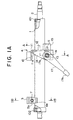
- FIG. 1A is a side view of the impact absorption type steering column apparatus for the automotive vehicle in a first embodiment of the present invention.
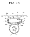
- FIG. 1B is an enlarged sectional view taken along the line 1B-1B in FIG. 1A.
- FIG. 2 is a plan view of the impact absorption type steering column apparatus for the automotive vehicle shown in FIG. 1A.
- FIG. 3 is a sectional view taken along the line A-A in FIG. 1A.
- FIG. 4 is a side view showing a state where the impact absorption type steering column apparatus for the automotive vehicle is installed in an actual car.
- FIG. 5 is a side view showing an operation following a secondary collision in the state where the impact absorption type steering column apparatus for the automotive vehicle is installed in the actual car.
- a steering shaft 2 is rotatably supported at both ends thereof through bearings 101, 102 within the steering column 1.
- This steering column 1 is secured to a car body at its lower end portion through a car body sided lower bracket 3 and at its intermediate portion through a car body sided upper bracket 4 (a bracket for a tilt adjustment) taking substantially an L-shape as viewed from a side.
- the car body sided lower bracket 3 and the car body sided upper bracket 4 are fixed to structural members (unillustrated) of the car body with bolts, etc..
- the car body sided lower bracket 3 is provided with a pair of car body securing portions 3a, 3b, and further with a pair of opposed right and left flat plate portions 3c, 3d extending substantially vertically from the pair of car body securing portions 3a, 3b.
- a column sided lower bracket 6 of the steering column 1 is fixed by welding to a cylindrical outer peripheral surface of the steering column 1.
- the column sided lower bracket 6 has opposed flat plate portions 6a, 6b facing the respective opposed flat plate portions 3c, 3d of the car body sided lower bracket 3. These opposed flat plate portions 6a, 6b are formed with round holes 6c, 6d.
- the opposed flat plate portions 6a, 6b of the column sided lower bracket 6 are slidably pinched in between the opposed flat plate portions 3c and 3d of the car body sided lower bracket 3.
- the opposed flat plate portions 3c, 3d of the car body sided lower bracket 3 are formed with cut-away portions 5a, 5b opened forwards of the automotive vehicle.
- car body sided lower bracket may be formed with the round holes, while the column sided lower bracket may be formed with the cut-aways opened in the opposite direction as a substitutive example for the illustrated example given above, thereby configuring the separation structure against the secondary collision.
- the car body sided upper bracket 4 taking substantially the L-shape is constructed integrally of a car body securing portion 10 secured to the car body with bolts, etc., vertical wall portions 12 bent substantially in an L-shape along bending portions 11 and extending downwards from a rear end of this car body securing portion 10, and column fastening fixing portions 14 erecting from the vertical wall portions 12 and extending sideways of the column 1 towards the front, the portions 14 having elongate holes 13 for a tilt adjustment.
- a column sided upper bracket 15 (a distance bracket) fixed by welding, etc. to both sides of a lower portion of the steering column 1, is provided in a press-fittable manner, and a tilt position fastening bolt 16 is inserted through the tilt adjustment elongate holes 13 of the column fastening fixing portions 14 and through-holes E of the column sided upper bracket 15.
- the through-hole E is an elongate hole extending backwards substantially in parallel with an axis of the column.
- the through-hole E may be given a proper change in its width from midways in the lengthwise direction, whereby a collapse characteristic can be given a variation.
- a contrivance is that with a swing of a fastening lever 17 attached to a proximal end portion of the tilt position fastening bolt 16, the car body sided upper bracket 4 presses and fixes the column sided upper bracket 15 so that the column apparatus can be fastened in a tilt position, or with a release of this pressing, the column apparatus can be released from the tilt position.
- the column apparatus when released from the tilt position, rotates about the bolt 7 and thus becomes adjustable of the tilt position.
- a handle member 17b of the fastening lever 17 is disposed more front side of the automotive vehicle than the proximal end portion 17a when in the tilt fastening operation.
- a proximal end portion of the tilt position fastening bolt 16 is provided with a cam lock mechanism.
- This cam lock mechanism is provided with a first cam 18 rotating together with the fastening lever 17, and an non-rotatable second cam 19 engaging with the first cam 18 and thus locking.
- a protrusion of the second cam 19 engages with the elongate hole 13 of the column fastening fixing portion 14, thus becoming non-rotatable.
- a sliding bearing 20 is interposed between the fastening lever 17 and the bolt head 16a.
- the fastening to the tilt position may be attained by a screw-based mechanism as a substitute for the cam lock mechanism.
- reinforcing beads 11a are formed in the bent portions 11 of the car body sided upper bracket 4.
- a bending load caused upon the secondary collision, i.e., an energy absorption characteristic can be adjusted by changing a size and a shape of the reinforcing bead 11a.
- the bent portion 11 and the vertical wall portion 12 are disposed, on the rear side of the automotive vehicle, at the car body securing portion 10 of the car body sided upper bracket 4, and the column fastening fixing portion 14 is disposed, on the front side of the automotive vehicle, at the vertical wall portion 12.
- the tilt position fastening bolt 16 comes to be positioned downwards substantially in the vertical direction of the bent portion 11.
- the column sided upper bracket 15 extends comparatively long towards the rear side of the automotive vehicle, and further the through-hole of the column sided upper bracket 15 is formed in an extra stroke area E as an elongate hole extending on the rear side of the automotive vehicle from the position of the tilt position fastening bolt 16.
- the column sided upper bracket 15 moves, with respect to the tilt position fastening bolt 16 of the car body sided upper bracket 4, together with the steering column 1 along the extra stroke area E as the elongate hole from a front side end down to a rear side end of this area E while engaging therewith towards the front of the automotive vehicle, and thus can make the collapse stroke.
- the elongate hole E for the extra stroke is not limited to being parallel with the steering shaft, and a collapse trajectory can be properly set by making the elongate hole E slant to the steering shaft, and so on.
- tilt position fastening bolt 16 moves down to the lowermost position of the tilt adjustment groove 13.
- the tilt position fastening bolt 16 which is disposed downwards substantially in the vertical direction, starts moving substantially in the horizontal direction by making the bent portion 11a to be a fulcrum and subsequently rotates about the bent portion 11 (fulcrum), however, the column sided lower bracket 6 separates from the car body sided lower bracket 3 downwardly of the steering column 2.
- the vertical wall portion 12 and the column fastening and fixing portion 14 of the car body sided upper bracket 4 becomes collapsed while making their flexural deformations so as to rotate about the bent portion 11 (the fulcrum), thereby absorbing an secondary impact energy.
- the bent portion 11 and the vertical wall portion 12 are disposed, on the rear side of the automotive vehicle, at the car body securing portion 10, and the column fastening and fixing portion 14 is disposed, on the front side of the automotive vehicle, at the vertical wall portion 12.
- the vertical wall portion 12 and the column fastening fixing portion 14 of the car body sided upper bracket 4 start moving in a direction of rotating about the bent portion 11 as the fulcrum, however, this direction is substantially the horizontal direction and is substantially coincident with an input (substantially horizontal) direction of the impact load exerted from the driver. Accordingly, the start of the movement of the car body sided upper bracket 4 can be stabilized when the secondary collision happens.
- the handle member 17b of the fastening lever 17 is disposed more front side of the automotive vehicle than the proximal end portion 17a thereof, and besides, as shown in FIG. 5, the fastening lever 17, following up the collapse of the car body sided upper bracket 4, moves towards the front of the automotive vehicle while rotating, and hence a safety of the car driver from a knee-hit against the fastening lever 17, can be further enhanced.
- the car body sided upper bracket 4 has the tilt adjustment elongate hole 13, and therefore, after the car body sided upper bracket 4 has been bent, the tilt adjustment elongate hole 13 becomes substantially parallel with a collapsing direction and the tilt adjustment elongate hole 13 also can be used for a part of the collapse stroke, whereby the collapse stroke can be further increased.
- the collapse stroke quantity in the steering column 1 can be further augmented.
- FIG. 6 shows a modified example of the first embodiment discussed above.
- a car body sided upper bracket (a tilt bracket) 4' shown in FIG. 6 a bent portion 11' and a vertical wall portion 12' are integrally formed at a front side end of a car body securing member 10', and a column fastening fixing portion 14' is disposed, on the rear side of the automotive vehicle, at the vertical wall portion 12'.
- the vertical wall portion 12' of the car body sided upper bracket exists more front side of the automotive vehicle than the vertical wall portion 12 in the above described first embodiment.
- the through-hole, for the fastening bolt 16, of the column sided upper bracket 15 extends towards the rear of the automotive vehicle.
- Other members have the same constructions as those in the first embodiment illustrated in FIG. 1A, and therefore the same members are shown by marking them with the like symbols, of which the explanations are omitted.
- the vertical wall portion 12' is provided more front side of the automotive vehicle than the vertical wall portion 12 in the first embodiment, and hence it is feasible to take a larger range of the swing of the steering column in the event of the secondary collision and therefore to take a larger collapse stroke.
- FIG. 7 is a side view of the impact absorption type steering column apparatus in a second embodiment of the present invention.
- FIG. 8 is a side view showing an operation following the secondary collision in the state where the impact absorption type steering column apparatus for the automotive vehicle is installed in the actual car.
- a flange of the car body securing portion 10 of the car body sided upper bracket 4 (the tilt adjustment bracket) is provided with a separation capsule 21, composed of a resin, for separating the car body sided upper bracket 4 from the car body upon the secondary collision. Owing to this capsule 21, upon the secondary collision, the car body sided upper bracket 4 separates from the car body and moves forwards without making the flexural deformation as in the first embodiment discussed above.
- the car body sided upper bracket 4 taking substantially the L-shape is constructed integrally of a car body securing portion 10 extending almost horizontally and secured to the car body with a bolt, etc., vertical wall portions 12 bent substantially in the L-shape along bent portions 11 and extending downwards from a front side end of this car body securing portion 10, and column fastening fixing portions 14 extending sideways of the column 1 substantially at a right-angled to the car body securing portion 10 and to the vertical wall portion 12 and extending sideways of the column 1, the portions 14 having the elongate holes 13 for the tilt adjustment.
- the vertical wall portions may not be provided.
- the column sided upper bracket 15 (the distance bracket) fixed by welding, etc. to both sides of the lower portion of the steering column 1, is press-fitted, and the tilt position fastening bolt 16 is inserted through the tilt adjustment elongate holes 13 of the column fastening fixing portions 14 and round through-holes of the column sided upper bracket 15.
- a contrivance is that with the swing of the fastening lever 17 attached to the proximal end portion of the tilt position fastening bolt 16, the car body sided upper bracket 4 presses and fixes the column sided upper bracket 15, so that the column apparatus can be fastened in a tilt adjusted position or with a release of this pressing, the column apparatus can be released from the tilt adjusted position.
- the column apparatus when released from the tilt adjusted position, can rotate about the bolt 7 and thus becomes adjustable of the tilt adjusting position.
- the handle portion 17b of the fastening lever 17 is disposed more front side of the automotive vehicle than the proximal end portion 17a thereof when in the tilt fastening operation.
- the proximal end portion of the tilt position fastening bolt 16 is provided with a cam lock mechanism.
- This cam lock mechanism is the same as in FIG. 3, and hence its explanation is omitted.
- a car body sided lower bracket 30 is of such a type as to absorb the impact energy by making the flexural deformation upon the secondary collision.
- the car body sided lower bracket 30 is integrally constructed of a car body securing portion 31 secured to the car body with a bolt, etc., a vertical wall portions 33 bent substantially in the L-shape along a bent portion 32 from a rear side end of the car body securing portion 31, and side plate portions 33a bent forwards at a right-angled from the vertical wall portions 33 and extending on both sides of the column.
- the energy absorption may be adjusted by providing ribs properly between the car body securing portion 31 and the vertical wall portion 33.
- the car body sided lower bracket 30 is formed with support holes 34.
- a lower bracket 36 is provided at a lower end of the steering column 1 integrally with or separately from the column 1.
- the lower bracket 36 integrally has side plates 36a internally abutting on the side plate portions 33a of the car body sided lower bracket 30 on both sides of the column.
- Each of these side plates 36a is formed with a through-hole corresponding to the support hole 34 of the car body sided lower bracket 30.
- a hinge pin 35 that defines a center of a tilt motion is inserted through between the support hole 34 and the through-hole of the column sided lower bracket 36 of the steering column 1.
- the through-holes formed in the side plates 36a of the column sided lower bracket 36 are configured in the extra stroke area E as elongate holes extending on the rear side of the automotive vehicle from a position of the tilt adjusting hinge pin 35.
- the extra stroke area E may be set parallel with or slant to the steering shaft.
- the energy may also be absorbed in the extra stroke area E, and the extra stroke area E may be given a proper change in its width from midways in the lengthwise direction, whereby a collapse characteristic can be given a variation.
- the tilt hinge pin 35 is disposed downwards substantially in the vertical direction of the bent portion 32.
- the tilt hinge pin 35 starts moving substantially in the horizontal direction with the bent portion 32 serving as a fulcrum and subsequently rotates about the bent portion 32 (the fulcrum).
- the vertical wall portions 33 becomes collapsed while making its flexural deformation so as to rotate about the bent portion 32 (the fulcrum), thereby absorbing the energy of the secondary collision.
- the collapse stroke quantity of the steering column throughout the extra stroke area E as the elongate hole of the column sided lower bracket 36, in addition to the collapse stroke quantity of the steering column due to the flexural deformation of the car body sided lower bracket 30. Accordingly, as required depending on the type of the automotive vehicle, its delivery destination and so forth, the collapse stroke quantity in the steering column 1 can be further augmented.
- the impact energy can be absorbed also by a friction caused by a caulking force of the tilt hinge pin 35.
- the car body sided upper bracket 4 may be set unseparable from the car body 10, and instead the distance bracket may be set separable when the secondary collision occurs.
- the column sided upper bracket 15 (the distance bracket) is provided separately from the steering column 1 in the embodiment discussed above and may also be formed integrally with the steering column 1 by hydrostatic bulge working, etc..
- the column sided bracket moves, with respect to the bolt of the car body sided bracket, together with the steering column along this elongate hole towards the front of the automotive vehicle while engaging therewith from the front side end to the rear side end, and thus make the collapse stroke.
- the collapse stroke quantity in the steering column can be further augmented.
Landscapes
- Engineering & Computer Science (AREA)
- Chemical & Material Sciences (AREA)
- Combustion & Propulsion (AREA)
- Transportation (AREA)
- Mechanical Engineering (AREA)
- Steering Controls (AREA)
Abstract
Description
Thus, according to the present invention, when the secondary collision happens, its impact energy is absorbed in a way that causes the flexural deformation of the car body sided bracket while moving the steering column towards the front of the automotive vehicle, and, on this occasion, the through-hole of the column sided bracket being formed as the elongate hole extending towards the rear side of the automotive vehicle from a bolt position, even after an end of the collapse stroke of the steering column due to the flexural deformation of the body sided bracket, the column sided bracket moves, with respect to the bolt of the car body sided bracket, together with the steering column along this elongate hole towards the front of the automotive vehicle while engaging therewith within a range of the front side end through the rear side end, and thus make the collapse stroke.
Claims (5)
- An impact absorption type steering column apparatus for an automotive vehicle in which a column sided bracket provided separately from or integrally with a steering column is press-fitted to a car body sided bracket secured to a car body, said steering column is supported by inserting a bolt through through-holes formed in said two brackets, and, when a secondary collision happens, an impact energy thereof is absorbed in a way that causes a flexural deformation of said car body sided bracket while moving said steering column towards the front of the automotive vehicle,
wherein in that said through-hole of said column sided bracket is formed as an elongate hole extending to the rear side of the automotive vehicle from a position of said bolt. - An impact absorption type steering column apparatus for an automotive vehicle according to claim 1, wherein said car body sided bracket is a car body sided upper,bracket, and
said column sided bracket is a column sided upper bracket. - An impact absorption type steering column apparatus for an automotive vehicle according to claim 2, wherein the through-hole of said car body sided upper bracket is an elongate hole for a tilt adjustment, and
said bolt is a tilt position fastening bolt. - An impact absorption type steering column apparatus for an automotive vehicle according to claim 1, wherein said car body sided bracket is a car body sided lower bracket, and
said column sided bracket is a column sided lower bracket. - An impact absorption type steering column apparatus for an automotive vehicle according to claim 4, wherein the hole of said car body sided lower bracket is a support hole for an adjustment of a tilt position, and
said bolt is a hinge pin for an adjustment of a tilt position that defines a tilt center.
Applications Claiming Priority (3)
| Application Number | Priority Date | Filing Date | Title |
|---|---|---|---|
| JP2002193628 | 2002-07-02 | ||
| JP2002193628 | 2002-07-02 | ||
| PCT/JP2003/008268 WO2004005109A1 (en) | 2002-07-02 | 2003-06-30 | Shock absorbing steering column device for vehicle |
Publications (3)
| Publication Number | Publication Date |
|---|---|
| EP1518775A1 true EP1518775A1 (en) | 2005-03-30 |
| EP1518775A4 EP1518775A4 (en) | 2006-06-07 |
| EP1518775B1 EP1518775B1 (en) | 2008-12-31 |
Family
ID=30112285
Family Applications (1)
| Application Number | Title | Priority Date | Filing Date |
|---|---|---|---|
| EP03738575A Expired - Lifetime EP1518775B1 (en) | 2002-07-02 | 2003-06-30 | Shock absorbing steering column device for vehicle |
Country Status (7)
| Country | Link |
|---|---|
| US (1) | US7384070B2 (en) |
| EP (1) | EP1518775B1 (en) |
| JP (1) | JPWO2004005109A1 (en) |
| CN (1) | CN100369780C (en) |
| AU (1) | AU2003246136A1 (en) |
| DE (1) | DE60325594D1 (en) |
| WO (1) | WO2004005109A1 (en) |
Cited By (1)
| Publication number | Priority date | Publication date | Assignee | Title |
|---|---|---|---|---|
| EP2671774A4 (en) * | 2011-02-02 | 2016-03-30 | Nsk Ltd | COLUMN UNIT FOR DIRECTION DEVICE WITH ELECTRICAL ASSISTANCE |
Families Citing this family (18)
| Publication number | Priority date | Publication date | Assignee | Title |
|---|---|---|---|---|
| WO2004005109A1 (en) * | 2002-07-02 | 2004-01-15 | Nsk Ltd. | Shock absorbing steering column device for vehicle |
| JP2004203164A (en) * | 2002-12-25 | 2004-07-22 | Fuji Kiko Co Ltd | Impact absorbing structure of vehicle steering system |
| GB0525850D0 (en) * | 2005-09-01 | 2006-02-01 | Trw Lucasvarity Electric Steer | A Steering Column Assembly |
| US7703804B2 (en) * | 2007-12-27 | 2010-04-27 | Gm Global Technology Operations, Inc. | Telescopically adjustable steering column assembly including an adjustment stop having minimal effect on impact loads |
| JP2010006323A (en) * | 2008-06-30 | 2010-01-14 | Jtekt Corp | Impact absorbing type steering device |
| US8555745B2 (en) * | 2009-04-20 | 2013-10-15 | Nsk Ltd. | Position adjustment device for steering wheel |
| DE102009021579A1 (en) * | 2009-05-15 | 2010-11-18 | Thyssenkrupp Presta Ag | Steering column for a motor vehicle |
| WO2011048883A1 (en) * | 2009-10-23 | 2011-04-28 | 日本精工株式会社 | Steering device |
| US8087490B2 (en) * | 2009-12-29 | 2012-01-03 | Kawasaki Jukogyo Kabushiki Kaisha | All terrain vehicle |
| KR20120006163A (en) * | 2010-07-12 | 2012-01-18 | 주식회사 만도 | Tilt hinge bracket of steering wheel of automobile and steering column of automobile having same |
| JP5499995B2 (en) * | 2010-08-26 | 2014-05-21 | 日本精工株式会社 | Shock absorbing steering device with electric power steering device |
| US9610971B2 (en) | 2011-02-02 | 2017-04-04 | Nsk Ltd. | Column unit for an electric power steering apparatus |
| EP2692610B1 (en) * | 2011-03-31 | 2016-08-24 | NSK Ltd. | Steering column device |
| JP5874361B2 (en) * | 2011-12-05 | 2016-03-02 | 日本精工株式会社 | Manufacturing method of steering device |
| PL3052370T3 (en) * | 2013-10-04 | 2017-12-29 | Nsk Americas, Inc. | Collapsible steering column assembly |
| JP6065992B2 (en) * | 2016-01-20 | 2017-01-25 | 日本精工株式会社 | Steering device |
| JP6119890B2 (en) * | 2016-02-18 | 2017-04-26 | 日本精工株式会社 | Steering device |
| CN109780513A (en) * | 2019-03-27 | 2019-05-21 | 杭叉集团股份有限公司 | A vehicle and a turn signal switch with a light-emitting element in its handle |
Family Cites Families (48)
| Publication number | Priority date | Publication date | Assignee | Title |
|---|---|---|---|---|
| IT1077203B (en) * | 1977-06-02 | 1985-05-04 | Alfa Romeo Spa | COLLAPSIBLE STEERING FOR A VEHICLE |
| WO1986001477A1 (en) * | 1984-08-27 | 1986-03-13 | Toyota Jidosha Kabushiki Kaisha | Structure for supporting a steering column tube |
| US4627306A (en) * | 1985-01-07 | 1986-12-09 | Ford Motor Company | Energy absorbing steering column for motor vehicles |
| JPS6223771A (en) | 1985-07-24 | 1987-01-31 | Nec Corp | Ribbon mask sheet having inclined blade |
| JPS6223771U (en) * | 1985-07-30 | 1987-02-13 | ||
| FR2588047B1 (en) * | 1985-09-30 | 1988-01-08 | Peugeot Cycles | FIXING DEVICE FOR A TUBULAR PART IN PARTICULAR FOR A VEHICLE STEERING COLUMN |
| JPH0517342Y2 (en) * | 1986-04-17 | 1993-05-10 | ||
| JPH0712215Y2 (en) * | 1988-06-17 | 1995-03-22 | 日本精工株式会社 | Shock absorption steering device |
| JPH08216Y2 (en) * | 1988-07-25 | 1996-01-10 | 日産自動車株式会社 | Energy absorption type steering column |
| JP2513633Y2 (en) * | 1990-11-02 | 1996-10-09 | 日本精工株式会社 | Shock absorption type steering column device |
| FR2672863B1 (en) * | 1991-02-15 | 1993-06-18 | Nacam | STEERING COLUMN DEVICE FOR MOTOR VEHICLE. |
| FR2714651B1 (en) * | 1994-01-06 | 1996-03-15 | Nacam | Energy absorption device for a motor vehicle steering column. |
| US5555772A (en) * | 1994-10-31 | 1996-09-17 | General Motors Corporation | Position control apparatus for steering column |
| JP3415953B2 (en) * | 1995-02-03 | 2003-06-09 | 日本精工株式会社 | Steering column support device |
| JPH08225079A (en) * | 1995-02-20 | 1996-09-03 | Nippon Seiko Kk | Shock absorption type steering column |
| EP0769445B1 (en) * | 1995-10-17 | 1999-01-20 | General Motors Corporation | Energy absorbing steering column for motor vehicle |
| DE69600661T2 (en) | 1995-10-20 | 1999-02-04 | Fuji Kiko Co. Ltd., Tokio/Tokyo | Steering column for a motor vehicle |
| JP2978788B2 (en) * | 1995-10-20 | 1999-11-15 | 富士機工株式会社 | Automotive steering column |
| US5605352A (en) * | 1995-12-08 | 1997-02-25 | General Motors Corporation | Energy absorbing steering column |
| US5645299A (en) * | 1996-05-31 | 1997-07-08 | Trw Inc. | Steering column support |
| JP3064912B2 (en) * | 1996-07-02 | 2000-07-12 | 富士機工株式会社 | Vehicle steering column |
| US5944348A (en) * | 1997-03-11 | 1999-08-31 | Daimlerchrysler Corporation | Collapsible steering column support structure |
| JP3396158B2 (en) * | 1997-12-26 | 2003-04-14 | 富士機工株式会社 | Energy absorption structure of steering column |
| JP3591284B2 (en) * | 1998-03-20 | 2004-11-17 | 日本精工株式会社 | Swing support device for steering column for tilt type steering device |
| CN1107608C (en) * | 1998-05-22 | 2003-05-07 | 克鲁普·普里斯塔公司 | Steering column crash system |
| US6147687A (en) * | 1998-10-02 | 2000-11-14 | International Business Machines Corporation | Dynamic and selective buffering tree view refresh with viewable pending notification |
| JP2000118415A (en) * | 1998-10-09 | 2000-04-25 | Fuji Kiko Co Ltd | Steering column |
| JP2000127991A (en) * | 1998-10-30 | 2000-05-09 | Nsk Ltd | Shock absorbing steering device and automobile |
| FR2788029B1 (en) * | 1999-01-06 | 2001-02-23 | Lemforder Nacam Sa | MODULAR ENERGY ABSORPTION DEVICE FROM A AUTOMOTIVE VEHICLE STEERING COLUMN |
| JP3560490B2 (en) * | 1999-02-10 | 2004-09-02 | 富士機工株式会社 | Energy absorption structure of steering column |
| JP3468711B2 (en) * | 1999-02-18 | 2003-11-17 | 株式会社山田製作所 | Steering column shock absorber |
| ES2157762B1 (en) * | 1999-02-26 | 2002-02-16 | Castellon Melchor Daumal | LONGITUDINAL GUIDANCE CONTROL SYSTEM FOR TELESCOPIC TREES AND / OR ASSEMBLIES WITH COLLAPSE MECHANISMS IN STEERING COLUMNS FOR AUTOMOBILE VEHICLES. |
| DE19933676C2 (en) * | 1999-07-17 | 2001-08-02 | Daimler Chrysler Ag | Steering arrangement for a motor vehicle |
| JP3727004B2 (en) * | 1999-09-10 | 2005-12-14 | 光洋精工株式会社 | Shock absorbing steering device and mounting member used therefor |
| JP2001106092A (en) * | 1999-10-07 | 2001-04-17 | Nsk Ltd | Tilt and telescopic steering system |
| FR2801269B1 (en) * | 1999-11-19 | 2002-02-08 | Nacam | MODULAR POWER ABSORBING DEVICE WITH PYROTECHNIC LOADS FROM A STEERING COLUMN OF A MOTOR VEHICLE |
| US6324935B1 (en) * | 1999-11-22 | 2001-12-04 | Daimlerchrysler Corporation | Collapsible steering assembly |
| JP3468742B2 (en) * | 2000-08-18 | 2003-11-17 | 株式会社山田製作所 | Rotation support structure of tilt steering |
| JP2003160051A (en) * | 2001-09-14 | 2003-06-03 | Nsk Ltd | Shock absorbing steering column device for vehicles |
| JP2003127874A (en) * | 2001-10-23 | 2003-05-08 | Fuji Kiko Co Ltd | Shock absorbing tilt steering column |
| EP1506903A4 (en) * | 2002-05-14 | 2006-06-28 | Nsk Ltd | Steering column device for vehicle and method of manufacturing the device |
| WO2004005109A1 (en) * | 2002-07-02 | 2004-01-15 | Nsk Ltd. | Shock absorbing steering column device for vehicle |
| EP1520768B1 (en) * | 2002-07-10 | 2010-04-14 | Nsk Ltd., | Vehicle shock absorption type steering column device |
| JP4239973B2 (en) * | 2002-07-17 | 2009-03-18 | 日本精工株式会社 | Steering column device |
| JP4124021B2 (en) * | 2002-10-07 | 2008-07-23 | トヨタ自動車株式会社 | Shock absorbing steering column device |
| JP2004203164A (en) * | 2002-12-25 | 2004-07-22 | Fuji Kiko Co Ltd | Impact absorbing structure of vehicle steering system |
| KR100510416B1 (en) * | 2003-09-06 | 2005-08-26 | 현대모비스 주식회사 | Energy absorbing tilting steering column for a vehicle |
| US7178833B2 (en) * | 2004-03-15 | 2007-02-20 | Delphi Technologies, Inc. | Steering column assembly with vertical capsules |
-
2003
- 2003-06-30 WO PCT/JP2003/008268 patent/WO2004005109A1/en not_active Ceased
- 2003-06-30 JP JP2004519216A patent/JPWO2004005109A1/en active Pending
- 2003-06-30 US US10/501,715 patent/US7384070B2/en not_active Expired - Lifetime
- 2003-06-30 EP EP03738575A patent/EP1518775B1/en not_active Expired - Lifetime
- 2003-06-30 CN CNB038045176A patent/CN100369780C/en not_active Expired - Fee Related
- 2003-06-30 DE DE60325594T patent/DE60325594D1/en not_active Expired - Lifetime
- 2003-06-30 AU AU2003246136A patent/AU2003246136A1/en not_active Abandoned
Cited By (2)
| Publication number | Priority date | Publication date | Assignee | Title |
|---|---|---|---|---|
| EP2671774A4 (en) * | 2011-02-02 | 2016-03-30 | Nsk Ltd | COLUMN UNIT FOR DIRECTION DEVICE WITH ELECTRICAL ASSISTANCE |
| EP3178722A1 (en) * | 2011-02-02 | 2017-06-14 | NSK Ltd. | Column unit for an electric power steering apparatus |
Also Published As
| Publication number | Publication date |
|---|---|
| WO2004005109A1 (en) | 2004-01-15 |
| US7384070B2 (en) | 2008-06-10 |
| EP1518775A4 (en) | 2006-06-07 |
| US20050093284A1 (en) | 2005-05-05 |
| CN1638995A (en) | 2005-07-13 |
| DE60325594D1 (en) | 2009-02-12 |
| EP1518775B1 (en) | 2008-12-31 |
| JPWO2004005109A1 (en) | 2005-11-04 |
| CN100369780C (en) | 2008-02-20 |
| AU2003246136A1 (en) | 2004-01-23 |
Similar Documents
| Publication | Publication Date | Title |
|---|---|---|
| US7384070B2 (en) | Shock absorbing steering column device for vehicle | |
| EP1762462B1 (en) | Steering apparatus | |
| US7311333B2 (en) | Vehicle shock absorption type steering column device | |
| JP6142969B2 (en) | Steering device | |
| CN108357560B (en) | Steering column | |
| US6345842B1 (en) | Shock absorbing type steering apparatus and a structure for mounting to an automobile body the steering apparatus | |
| JP4354742B2 (en) | Vehicle steering column device | |
| JPWO2016186149A1 (en) | Steering device | |
| JP2010089612A (en) | Shock absorbing type steering column device | |
| KR20200070086A (en) | Steering Column for Vehicle | |
| CN115465352A (en) | Steering device | |
| US7134692B2 (en) | Impact absorbing structure for vehicle steering systems | |
| US7125046B2 (en) | Shock absorbing steering column device for vehicle | |
| JP2978788B2 (en) | Automotive steering column | |
| JPH08295251A (en) | Shock absorption type steering column device | |
| JP5553005B2 (en) | Steering column support device | |
| JPH09193812A (en) | Shock absorption type steering column device | |
| KR101190734B1 (en) | Steering column with tilt and telescopic apparatus mixed for vehicle | |
| CN115465353A (en) | Steering device | |
| US20050066760A1 (en) | Column shifter with impact absorbing structure | |
| JP5327189B2 (en) | Steering column support device and assembly method thereof | |
| JP2002308117A (en) | Shock absorbing type steering device | |
| JP3914772B2 (en) | Shock absorbing steering device | |
| JP4696517B2 (en) | Telescopic structure and vehicle steering column device | |
| JP2008018820A (en) | Shock absorbing steering column device |
Legal Events
| Date | Code | Title | Description |
|---|---|---|---|
| PUAI | Public reference made under article 153(3) epc to a published international application that has entered the european phase |
Free format text: ORIGINAL CODE: 0009012 |
|
| 17P | Request for examination filed |
Effective date: 20040805 |
|
| AK | Designated contracting states |
Kind code of ref document: A1 Designated state(s): AT BE BG CH CY CZ DE DK EE ES FI FR GB GR HU IE IT LI LU MC NL PT RO SE SI SK TR |
|
| AX | Request for extension of the european patent |
Extension state: AL LT LV MK |
|
| DAX | Request for extension of the european patent (deleted) | ||
| RBV | Designated contracting states (corrected) |
Designated state(s): DE GB |
|
| A4 | Supplementary search report drawn up and despatched |
Effective date: 20060504 |
|
| 17Q | First examination report despatched |
Effective date: 20070322 |
|
| GRAP | Despatch of communication of intention to grant a patent |
Free format text: ORIGINAL CODE: EPIDOSNIGR1 |
|
| GRAS | Grant fee paid |
Free format text: ORIGINAL CODE: EPIDOSNIGR3 |
|
| GRAS | Grant fee paid |
Free format text: ORIGINAL CODE: EPIDOSNIGR3 |
|
| GRAA | (expected) grant |
Free format text: ORIGINAL CODE: 0009210 |
|
| AK | Designated contracting states |
Kind code of ref document: B1 Designated state(s): DE GB |
|
| REG | Reference to a national code |
Ref country code: GB Ref legal event code: FG4D |
|
| REF | Corresponds to: |
Ref document number: 60325594 Country of ref document: DE Date of ref document: 20090212 Kind code of ref document: P |
|
| PLBE | No opposition filed within time limit |
Free format text: ORIGINAL CODE: 0009261 |
|
| STAA | Information on the status of an ep patent application or granted ep patent |
Free format text: STATUS: NO OPPOSITION FILED WITHIN TIME LIMIT |
|
| PGFP | Annual fee paid to national office [announced via postgrant information from national office to epo] |
Ref country code: GB Payment date: 20090624 Year of fee payment: 7 |
|
| 26N | No opposition filed |
Effective date: 20091001 |
|
| GBPC | Gb: european patent ceased through non-payment of renewal fee |
Effective date: 20100630 |
|
| PG25 | Lapsed in a contracting state [announced via postgrant information from national office to epo] |
Ref country code: GB Free format text: LAPSE BECAUSE OF NON-PAYMENT OF DUE FEES Effective date: 20100630 |
|
| PGFP | Annual fee paid to national office [announced via postgrant information from national office to epo] |
Ref country code: DE Payment date: 20180619 Year of fee payment: 16 |
|
| REG | Reference to a national code |
Ref country code: DE Ref legal event code: R119 Ref document number: 60325594 Country of ref document: DE |
|
| PG25 | Lapsed in a contracting state [announced via postgrant information from national office to epo] |
Ref country code: DE Free format text: LAPSE BECAUSE OF NON-PAYMENT OF DUE FEES Effective date: 20200101 |