EP1518655A1 - Apparatus for and process of gas-assisted injection molding of plastics material - Google Patents
Apparatus for and process of gas-assisted injection molding of plastics material Download PDFInfo
- Publication number
- EP1518655A1 EP1518655A1 EP03016876A EP03016876A EP1518655A1 EP 1518655 A1 EP1518655 A1 EP 1518655A1 EP 03016876 A EP03016876 A EP 03016876A EP 03016876 A EP03016876 A EP 03016876A EP 1518655 A1 EP1518655 A1 EP 1518655A1
- Authority
- EP
- European Patent Office
- Prior art keywords
- molding
- plastics material
- pressurized fluid
- injection
- assembly
- Prior art date
- Legal status (The legal status is an assumption and is not a legal conclusion. Google has not performed a legal analysis and makes no representation as to the accuracy of the status listed.)
- Pending
Links
- 239000000463 material Substances 0.000 title claims abstract description 66
- 239000004033 plastic Substances 0.000 title claims abstract description 65
- 229920003023 plastic Polymers 0.000 title claims abstract description 65
- 238000001746 injection moulding Methods 0.000 title claims abstract description 8
- 238000000034 method Methods 0.000 title claims description 12
- 238000000465 moulding Methods 0.000 claims abstract description 83
- 239000012530 fluid Substances 0.000 claims abstract description 34
- 238000002347 injection Methods 0.000 claims abstract description 28
- 239000007924 injection Substances 0.000 claims abstract description 28
- 238000001816 cooling Methods 0.000 claims description 16
- 238000007599 discharging Methods 0.000 claims description 5
- 230000000063 preceeding effect Effects 0.000 claims 1
- 230000008878 coupling Effects 0.000 description 9
- 238000010168 coupling process Methods 0.000 description 9
- 238000005859 coupling reaction Methods 0.000 description 9
- 238000004519 manufacturing process Methods 0.000 description 9
- 239000007789 gas Substances 0.000 description 6
- IJGRMHOSHXDMSA-UHFFFAOYSA-N Atomic nitrogen Chemical compound N#N IJGRMHOSHXDMSA-UHFFFAOYSA-N 0.000 description 4
- 239000000945 filler Substances 0.000 description 2
- 229910052757 nitrogen Inorganic materials 0.000 description 2
- 230000000712 assembly Effects 0.000 description 1
- 238000000429 assembly Methods 0.000 description 1
- 230000015572 biosynthetic process Effects 0.000 description 1
- 230000001419 dependent effect Effects 0.000 description 1
- 230000002452 interceptive effect Effects 0.000 description 1
- 239000007788 liquid Substances 0.000 description 1
- 230000014759 maintenance of location Effects 0.000 description 1
- 230000000704 physical effect Effects 0.000 description 1
- 238000010583 slow cooling Methods 0.000 description 1
- XLYOFNOQVPJJNP-UHFFFAOYSA-N water Substances O XLYOFNOQVPJJNP-UHFFFAOYSA-N 0.000 description 1
Images

Classifications
-
- B—PERFORMING OPERATIONS; TRANSPORTING
- B29—WORKING OF PLASTICS; WORKING OF SUBSTANCES IN A PLASTIC STATE IN GENERAL
- B29C—SHAPING OR JOINING OF PLASTICS; SHAPING OF MATERIAL IN A PLASTIC STATE, NOT OTHERWISE PROVIDED FOR; AFTER-TREATMENT OF THE SHAPED PRODUCTS, e.g. REPAIRING
- B29C45/00—Injection moulding, i.e. forcing the required volume of moulding material through a nozzle into a closed mould; Apparatus therefor
- B29C45/17—Component parts, details or accessories; Auxiliary operations
- B29C45/1703—Introducing an auxiliary fluid into the mould
- B29C45/1704—Introducing an auxiliary fluid into the mould the fluid being introduced into the interior of the injected material which is still in a molten state, e.g. for producing hollow articles
-
- B—PERFORMING OPERATIONS; TRANSPORTING
- B29—WORKING OF PLASTICS; WORKING OF SUBSTANCES IN A PLASTIC STATE IN GENERAL
- B29C—SHAPING OR JOINING OF PLASTICS; SHAPING OF MATERIAL IN A PLASTIC STATE, NOT OTHERWISE PROVIDED FOR; AFTER-TREATMENT OF THE SHAPED PRODUCTS, e.g. REPAIRING
- B29C45/00—Injection moulding, i.e. forcing the required volume of moulding material through a nozzle into a closed mould; Apparatus therefor
- B29C45/03—Injection moulding apparatus
- B29C45/04—Injection moulding apparatus using movable moulds or mould halves
- B29C45/0408—Injection moulding apparatus using movable moulds or mould halves involving at least a linear movement
-
- B—PERFORMING OPERATIONS; TRANSPORTING
- B29—WORKING OF PLASTICS; WORKING OF SUBSTANCES IN A PLASTIC STATE IN GENERAL
- B29C—SHAPING OR JOINING OF PLASTICS; SHAPING OF MATERIAL IN A PLASTIC STATE, NOT OTHERWISE PROVIDED FOR; AFTER-TREATMENT OF THE SHAPED PRODUCTS, e.g. REPAIRING
- B29C45/00—Injection moulding, i.e. forcing the required volume of moulding material through a nozzle into a closed mould; Apparatus therefor
- B29C45/17—Component parts, details or accessories; Auxiliary operations
- B29C45/1703—Introducing an auxiliary fluid into the mould
- B29C45/1704—Introducing an auxiliary fluid into the mould the fluid being introduced into the interior of the injected material which is still in a molten state, e.g. for producing hollow articles
- B29C45/1706—Introducing an auxiliary fluid into the mould the fluid being introduced into the interior of the injected material which is still in a molten state, e.g. for producing hollow articles using particular fluids or fluid generating substances
- B29C2045/1707—Introducing an auxiliary fluid into the mould the fluid being introduced into the interior of the injected material which is still in a molten state, e.g. for producing hollow articles using particular fluids or fluid generating substances using a liquid, e.g. water
-
- B—PERFORMING OPERATIONS; TRANSPORTING
- B29—WORKING OF PLASTICS; WORKING OF SUBSTANCES IN A PLASTIC STATE IN GENERAL
- B29C—SHAPING OR JOINING OF PLASTICS; SHAPING OF MATERIAL IN A PLASTIC STATE, NOT OTHERWISE PROVIDED FOR; AFTER-TREATMENT OF THE SHAPED PRODUCTS, e.g. REPAIRING
- B29C45/00—Injection moulding, i.e. forcing the required volume of moulding material through a nozzle into a closed mould; Apparatus therefor
- B29C45/17—Component parts, details or accessories; Auxiliary operations
- B29C45/1703—Introducing an auxiliary fluid into the mould
- B29C45/1732—Control circuits therefor
Definitions
- the invention refers to an apparatus and process for injection molding articles of plastics material, according to the preamble of Claim 1, particularly an apparatus and process for manufacturing articles of plastics materials having an outer layer structurally different from the inner part.
- the surface finish of the articles manufactured accordingly is basically inferior because the plastics material used as filler does not have a pressure as high as the pressure of the fluid used to form hollow articles. Therefore, there is still the technical problem of performing quickly at low cost molding processes capable of obtaining the same quality level of the hollow articles.
- each pair of mold 2a and countermold 2b defines at least one molding cavity 7 having the shape of the article to be molded in plastics material.
- Molding units 3 are relatively movable with respect to injection assembly 8 and auxiliary assembly 9 and removable connecting devices are provided. Indeed, referring to auxiliary assembly 9, feeding ducts 10 defined between each molding cavity 7 and auxiliary assembly 9, comprise initial segments 11a engaged with the auxiliary assembly 9 and final segments 11b engaged with molding unit 3, which segments 11 a and 11b are removably engaged to each other by means of removable connecting devices embodied by a quick-connection device 12 .
- This quick-connection device 12 can have different structures and an exemplary embodiment is shown in Fig. 2.
- Quick-connection devices are known.
- one of these devices can be an "automatic coupler" manufactured by Enerpac Automatic Systems (Milwaukee, WI, U.S.A.) or a quick-connection coupling manufactured by Stäubli Italia S.p.A., Divisione Raccordi (Carate Brianza, Milano, Italia).
- Injection assembly 8 can be made in order to be capable to deliver only one or more plastics materials adapted to form two layers one inside the other. When only one plastics material is delivered, as shown ( Figure 1), supplying channels 18 are provided between each molding cavity 7 and injection assembly 8.
- Removable connecting devices between injection assembly 8 and molding units 3 are formed by a movable injector 8a forming the end portion of injection assembly 8.
- Shut-off devices 20a comprise, as shown in Fig. 1, at least on stop valve. 21 adapted to avoid a counter flow of pressurized fluid exiting from molding cavity 7 - and allow a flow in the opposite direction - and at least one manually operated valve 22 for discharging the pressurized fluid.
- a guard 23a located at the end of discharge portion 23 avoids damages from discharging pressurized gas.
- One-way elements 20b keeping plastics material in molding cavity 7 are inserted in each supplying channels 18, and for example are formed by at least one conical inlet or channel 24 narrowing towards movable injector 8a made in the sleeve.
- Plastics material contained in channel 24 quickly cools down and takes the shape of conical plug preventing the still melted pressurized plastics material from escaping from molding cavity 7.
- One-way elements 20b can be at least one stop valve of the kind shown by reference 21 and located adjacent sleeve 19.
- the length of path 25 or the time for travelling it are proportional to the cooling time.
- the first and last stations 26, 30 are provided near injection assembly 8 and auxiliary assembly 9, where is located the personnel, and a substantial part of the path is for cooling the plastics material in molding units in the presence of the pressurized fluid.
- the presence of the inner cavity can draw the plastics material which almost collapses when the articles are removed before the plastics material has completely cooled and hardened.
- molding units 3 do not stay stationary waiting their proper cooling, but they are moved to cooling stations thanks to the quick-connection device 12 and movable injector 8a which can interrupt the supply from feeding ducts 10 and supplying channels 18.
- the invention also teaches a new process for injection molding article of plastics material.
- the new process comprises at least one initial step for injecting melted plastics material and at least one initial step for introducing a pressurized fluid in the molding cavities defined in molding units.
- a step for discharging the pressurized fluid is carried out before opening the molding units.
- the products manufactured are both lightweight and inexpensive thanks to the inner cavity, moreover the outer layer or crust shows a very detailed appearance, for example smooth and soft, and the inner layer or core located between the crust and cavity shows the greatest strength.
Landscapes
- Engineering & Computer Science (AREA)
- Manufacturing & Machinery (AREA)
- Mechanical Engineering (AREA)
- Moulds For Moulding Plastics Or The Like (AREA)
- Injection Moulding Of Plastics Or The Like (AREA)
Abstract
Description
- The invention refers to an apparatus and process for injection molding articles of plastics material, according to the preamble of
Claim 1, particularly an apparatus and process for manufacturing articles of plastics materials having an outer layer structurally different from the inner part. - As it is known, it is widely used a particular kind of injection molding for manufacturing different articles and objects provided with an outer layer made of a proper plastics material and an inner hollow core.
- This molding comprises a number of steps of: supplying a selected quantity of a melted plastics material, immediately after supplying a high pressure fluid so that said fluid drives and compels the plastics material against the mold surfaces, keeping this state for a time sufficient to set the plastics material. Finally, the pressurized fluid is discharged. Discharge is performed before opening the mold for demolding a molded article.
- Pressurized fluid for forming hollow articles can be a gas, such as air or nitrogen, or a liquid, such as water.
- Referring particularly to substantially hollow articles, said molding offers two advantages: it is possible to manufacture structures which are both lightweight and inexpensive, despite the use of a valuable plastics material.
- Indeed, it is sufficient a relatively small quantity of this plastics material because it is distributed only as an outer layer of the molded articles.
- This kind of molding shows other advantages.
- It allows to optimally distribute the plastics material in the molding cavity, even though it is injected from only one location.
- It is also possible to manufacture the thinner portions of the molded articles, indeed the plastics material is compelled to perfectly enter every recess of the mold.
- Every part on the surface of these articles shows the same excellent surface finish, moreover every part of the molding cavity of the molds is subjected to uniform pressures.
- The procedure and equipment used for molding said articles show, despite these advantages, the severe disadvantage of a low production rate.
- Indeed, while the first two steps are carried out one after the other in a short period of time, the third step of setting the plastics material compelled along the periphery of molding cavity by the pressurized fluid takes a lot of time because of a slow cooling and due to the fact the cooling time cannot be shortened.
- Indeed, the longer step for cooling and setting the plastics material contained in the mold is, the fewer local shrinkages of the plastics material will appear when it is demolded. Moreover, the longer this step lasts, the smoother plastics surfaces will be because they will take the finish surface of the molding cavity.
- Briefly, the retention time of the plastics material inside the pressurized mold determines the quality level and finish of the products.
- The extended residence time of the plastics material in the molds determines also high cost of the molding plants when it is necessary to increase the production levels.
- The cost depends on the fact that must be provided many molding stations simultaneously operating, alternatively large apparatus must be provided capable of operating at the same time a number of molds.
- In other words, the prior art in order to obtain high production levels and/or suitable plant cost, must minimize the cooling time of the plastics material in the molds and/or the number of operating molding apparatus in view of the minimum required quality level of the molded articles determined from time to time by the specific articles to be obtained.
- In this field, it is still widely used another kind of molding for obtaining an outer layer structurally different from the inner part.
- This kind of molding is called bicomponent molding, which forms an outer layer made of valuable material and an inner core made of inexpensive plastics material. Therefore the articles do not have hollow parts, however the cost of the plastics material is kept low even though the outer appearance shows a high level quality.
- This molding comprises the steps of supplying a predetermined quantity of melted plastics material adapted to form the outer layer, then supplying a second melted plastics material in order to drive and compel the former against the mold surfaces.
- This kind of molding does not require long cooling and setting times with the molds in a closed condition. Another advantage of this molding consists of using a plastics material inside the articles that acts not just as a simple filler but also confers maximum solidity to the articles.
- Unfortunately the bicomponent molding is not capable of manufacturing articles as light as the hollow articles.
- Moreover, the surface finish of the articles manufactured accordingly is basically inferior because the plastics material used as filler does not have a pressure as high as the pressure of the fluid used to form hollow articles. Therefore, there is still the technical problem of performing quickly at low cost molding processes capable of obtaining the same quality level of the hollow articles.
- Under these circumstances, the object of the present invention is to remedy the disadvantages of the prior art and to solve said technical problem.
- Said object is achieved by an apparatus for injection molding articles of plastics material as claimed in the annexed main Claims.
- Preferred embodiments of the invention are specified in the dependent Claims.
- Other features and advantages will be better understood from the following detailed description of a molding apparatus and process according to the invention shown in the attached drawings, wherein:
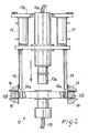
- Figure 1 is a simplified partial cross-section front view of a portion of the apparatus;
- Figure 2 is a detail of figure 1; and
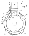
- Figure 3 is a simplified plan view of whole apparatus.
- In said Figures, the apparatus according to the invention has been generally shown by the
reference number 1, referring to an embodiment of the same for forming hollow articles provided with only one outer layer. -
Apparatus 1 substantially comprises a plurality ofmolds 2a and countermolds 2b reciprocally movable from an open to a closed condition and forming together a plurality ofmolding units 3. - As schematically shown in figure 1, the
mold 2a and countermold 2b of eachmolding unit 3 are associated toplates 4 respectively which in turn are slidably connected to each other by studs 5. The opening and closing operations are performed by pistons 6. - In the closed position, each pair of
mold 2a and countermold 2b defines at least onemolding cavity 7 having the shape of the article to be molded in plastics material. - The plastics material is supplied in melted state by an
injection assembly 8 which is known per se (Fig. 3). - The molding is of the kind known as "gas assisted" molding, in other words, after the plastics material injection, a pressurized fluid is injected, such as gas comprising air, nitrogen, etc. This gas is supplied at a very high pressure inside the melted plastics material so that the latter is compressed against the periphery of the
molding cavity 7. - To this end it is provided an
auxiliary assembly 9 delivering pressurized fluid. Thisauxiliary assembly 9 is known per se known and it is schematically shown in Figure 3. -
Molding units 3 are relatively movable with respect toinjection assembly 8 andauxiliary assembly 9 and removable connecting devices are provided. Indeed, referring toauxiliary assembly 9,feeding ducts 10 defined between eachmolding cavity 7 andauxiliary assembly 9, compriseinitial segments 11a engaged with theauxiliary assembly 9 andfinal segments 11b engaged withmolding unit 3, whichsegments connection device 12. - This quick-
connection device 12 can have different structures and an exemplary embodiment is shown in Fig. 2. - Figure 2 shows that a
male coupling 13a, connected toinitial segments 11a, can be sealingly inserted into a female coupling 13b connected tofinal segments 11 b. - Both
couplings 13a, 13b are guided by centeringstuds 14 integral withmale coupling 13a and connected to it by a first plate 15a. - Female coupling 13b is in turn integral with a
second plate 15b which is provided with centeringholes 14a receiving centeringstuds 14.Second plate 15b is removably received betweenstationary stops 16 and first plate 15a is controlled to movemale coupling 13a until it sealingly engages female coupling 13b. - The movement is resulted by two
small pistons 17 supported by astationary support element 17a and both acting on first plate 15a. - Both couplings are also respectively disengaged by
pistons 17. - Other quick-connection devices are known. For example one of these devices can be an "automatic coupler" manufactured by Enerpac Automatic Systems (Milwaukee, WI, U.S.A.) or a quick-connection coupling manufactured by Stäubli Italia S.p.A., Divisione Raccordi (Carate Brianza, Milano, Italia).
Injection assembly 8 can be made in order to be capable to deliver only one or more plastics materials adapted to form two layers one inside the other. When only one plastics material is delivered, as shown (Figure 1), supplyingchannels 18 are provided between eachmolding cavity 7 andinjection assembly 8. - Removable connecting devices between
injection assembly 8 andmolding units 3 are formed by amovable injector 8a forming the end portion ofinjection assembly 8. - Indeed, at each injection,
movable injector 8a can be located on an opening made in asleeve 19 surrounding the inlet of eachsupplying channels 18 of eachmolding unit 3. - In Fig. 1, a single basal injection is defined by
sleeve 19, that is a single injection point for introducing plastics material perpendicularly to one of the major surfaces ofmolding cavity 7. - Then
molding units 3 are associated to check means 20 avoiding counter flows from moldingcavities 7. - Check means 20 comprises shut-off
devices 20a adapted to keep the pressurized fluid insidemolding cavity 7 or one-way elements 20b for keeping plastics material insidemolding cavity 7. - Shut-off
devices 20a are located infinal segments 11b offeeding ducts 10 and are movable withfinal segments 11 b andmolding units 3 engaged withfinal segments 11 b. - Shut-
off devices 20a comprise, as shown in Fig. 1, at least on stop valve. 21 adapted to avoid a counter flow of pressurized fluid exiting from molding cavity 7 - and allow a flow in the opposite direction - and at least one manually operatedvalve 22 for discharging the pressurized fluid. - Advantageously,
discharge valve 22 is an electrical valve and it is located in its own duct made in adischarge portion 23 branching fromfinal segments 11 b. - A
guard 23a located at the end ofdischarge portion 23 avoids damages from discharging pressurized gas. - One-way elements 20b keeping plastics material in
molding cavity 7 are inserted in each supplyingchannels 18, and for example are formed by at least one conical inlet orchannel 24 narrowing towardsmovable injector 8a made in the sleeve. - Plastics material contained in
channel 24 quickly cools down and takes the shape of conical plug preventing the still melted pressurized plastics material from escaping frommolding cavity 7. - One-way elements 20b can be at least one stop valve of the kind shown by
reference 21 and locatedadjacent sleeve 19. - Preferably, as shown in Fig. 3,
injection assembly 8 supplying melted plastics material, andauxiliary assembly 9 supplying pressurized fluid are substantially stationary, whilemolding units 3 are movable along a substantially closed-loop path 25, for example a circular path.Path 25 is defined by tracks along whichmolding assemblies 3 are moved. - Working stations comprising plastics material injection and pressurized
fluid supplying stations 26,cooling stations materials demolding stations 30, for example, are located alongpath 25. - The length of
path 25 or the time for travelling it are proportional to the cooling time. The first andlast stations injection assembly 8 andauxiliary assembly 9, where is located the personnel, and a substantial part of the path is for cooling the plastics material in molding units in the presence of the pressurized fluid. - Other arrangements are possible. For example molding units can be substantially reciprocally aligned and stationary, while
injection assembly 8 andauxiliary assembly 9 adjacent to stations are movable. - Operation of the apparatus described above mainly as regards structure is as follows.
- The
injection assembly 8 and theauxiliary assembly 9 operate in a manner per se known: plastics material and fluid, particularly a gas, are injected inmolding units 3, the plastics material is compelled by pressure of the fluid in order to precisely adhere to inner surfaces ofmolding cavity 7. - Injected plastics material can define only one outer layer, or two or more reciprocally overlapped layers, as it is done with the bicomponent molding. Pressurized fluid introduced inside the plastics material forms articles and artifacts provided with an inner cavity.
- The presence of the inner cavity can draw the plastics material which almost collapses when the articles are removed before the plastics material has completely cooled and hardened.
- Thus, a period of time must elapse between the plastics material injection and the
injection units 3 opening, after having discharged the pressurized fluid. However,molding units 3 do not stay stationary waiting their proper cooling, but they are moved to cooling stations thanks to the quick-connection device 12 andmovable injector 8a which can interrupt the supply from feedingducts 10 and supplyingchannels 18. - Additionally, the fluid loss from the
molding cavity 3 is prevented by check means 20, that is to say shut-offdevices 20a located in the feedingducts 10 and the one-way elements 24 in the supplying channels18. - The cooling can therefore last a lot of time without interfering with the operation of
injection assembly 8 andauxiliary assembly 9 ofother molding units 3. - The invention also teaches a new process for injection molding article of plastics material.
- The new process comprises at least one initial step for injecting melted plastics material and at least one initial step for introducing a pressurized fluid in the molding cavities defined in molding units.
- Afterwards, there are the intermediate steps for cooling and hardening the plastics material contained in the molding cavities with the pressurized fluid, and final steps comprising the articles demolding.
- Plastics material and pressurized fluid are kept in the molding units which are then moved in order to carry out some of the said steps, particularly the cooling steps, in a location remote from that of the other steps.
- In this way some of the different steps can be carried out substantially at the same time by different molding units.
- After the cooling step, a step for discharging the pressurized fluid is carried out before opening the molding units.
- It is to be noted that the initial steps of injecting melted plastics material can comprise the formation of more than one substantially concentric layers having different structures: for example a relatively thin outer layer made of a very valuable material and selected according to its appearance and pleasantness to the touch, and an inexpensive inner layer selected according to its physical properties, for example because it is strong to mechanical loads.
- The plastics material products manufactured by the present process combine the best features of the hollow articles with the best features of the bicomponent-type articles.
- Stated differently, the products manufactured are both lightweight and inexpensive thanks to the inner cavity, moreover the outer layer or crust shows a very detailed appearance, for example smooth and soft, and the inner layer or core located between the crust and cavity shows the greatest strength.
- The invention achieves important advantages.
- Indeed, a molding apparatus and process have been envisaged which allow to keep for a long period injected plastics material inside the molds with the pressurized fluid, without reducing the productivity and requiring very expensive plants.
- Moreover, the cooling step of these molding units can lasts much longer than the standard one for manufacturing articles, in order to obtain a surface finish that is fully satisfactory.
Claims (12)
- Apparatus for injection molding articles of plastics material, comprising: molds (2a) and countermolds (2b) forming a plurality of molding units (3), molding cavities (7) being defined inside said molds and countermolds; at least one injection assembly (8) and at least one auxiliary assembly (9) adapted to respectively supply melted plastics material and pressurized fluid into said molding cavities (7);characterized in that said molding units (3) are movable with respect to said injection assembly (8) and auxiliary assembly (9); and in that removable connecting devices (12, 8a), and check means (20) adapted to avoid counter flows from said molding cavities (7), are provided between said molding units (3) and said injection assembly (8) and said auxiliary assembly (9).
- Apparatus according to Claim 1, wherein feeding ducts (10) extend between said auxiliary assembly (9) and said molding cavity (7), said feeding ducts (10) comprising initial segments (11a) engaged with said auxiliary assembly (9) and final segments (11b) engaged with said molding units (3) and removably connected to said initial segments (11a), and wherein said check means (20) comprises shut-off devices (20a) connected to said final segments (11b) and adapted to prevent said pressurized fluid from flowing back to said molding cavities (7).
- Apparatus according to Claim 2, wherein said shut-off devices (20a) comprise at least one stop valve (21) adapted to prevent the pressurized fluid from flowing back from said molding cavity (7), and at least one manually operated discharge valve (22) for said fluid.
- Apparatus according to Claim 3, wherein said final segments (11b) comprise a discharge portion (23) connected to said discharge valve (22), and wherein said discharge valve (22) is an electric valve.
- Apparatus according to Claim 2, wherein said removable connecting devices comprise a quick-connection device (12) inserted between said initial segments (11a) and said final segments (11b).
- Apparatus according to one or more of the preceeding Claims, in particular Claim 1, wherein supplying channels (18) extends between said injection assembly (8) and molding cavity (7), and wherein said removable connecting devices comprise, in said supplying channels (18), at least one movable injector (8a) located between said injection assembly (8) and said molding units (3).
- Apparatus according to Claim 6, wherein said check means (20) in said supplying channels (18) comprises one-way elements (20b) for the plastics materials.
- Apparatus according to Claim 7, wherein said one-way elements (20b) are formed by at least one conical channel (24) made in said molding units (3).
- Apparatus according to Claim 7, wherein said one-way elements (20b) are formed by at least one stop valve.
- Apparatus according to Claim 1, wherein said injection assembly (8) and said auxiliary assembly (9) are substantially stationary, and wherein said molding units (3) are movable along a substantially closed-loop path (25).
- Apparatus according to Claim 10, wherein working stations are provided along said path (25), said working stations comprising plastics material injection and pressurized fluid supplying (26), cooling (27, 28, 29), pressurized fluid discharging and demolding (30) stations.
- Process for injection molding articles of plastics materials, comprising: at least one step for injecting melted plastics material in molding cavities made in molding units, at least one step for introducing a pressurized fluid inside said plastics material, steps for cooling and hardening said plastics materials inside said cavities, with said pressurized fluid, and final steps comprising the demolding of the molded articles,the process being characterized in that is comprises momentarily keeping said plastics material and said pressurized fluid inside said molding units, moving said molding units, and carrying out some of said steps in reciprocally distinct positions in order to contemporaneously carry out some of them.
Priority Applications (1)
| Application Number | Priority Date | Filing Date | Title |
|---|---|---|---|
| EP03016876A EP1518655A1 (en) | 2003-07-24 | 2003-07-24 | Apparatus for and process of gas-assisted injection molding of plastics material |
Applications Claiming Priority (1)
| Application Number | Priority Date | Filing Date | Title |
|---|---|---|---|
| EP03016876A EP1518655A1 (en) | 2003-07-24 | 2003-07-24 | Apparatus for and process of gas-assisted injection molding of plastics material |
Publications (1)
| Publication Number | Publication Date |
|---|---|
| EP1518655A1 true EP1518655A1 (en) | 2005-03-30 |
Family
ID=34178380
Family Applications (1)
| Application Number | Title | Priority Date | Filing Date |
|---|---|---|---|
| EP03016876A Pending EP1518655A1 (en) | 2003-07-24 | 2003-07-24 | Apparatus for and process of gas-assisted injection molding of plastics material |
Country Status (1)
| Country | Link |
|---|---|
| EP (1) | EP1518655A1 (en) |
Cited By (2)
| Publication number | Priority date | Publication date | Assignee | Title |
|---|---|---|---|---|
| RU2697712C2 (en) * | 2011-04-22 | 2019-08-19 | СИГНАЛ ФАРМАСЬЮТИКАЛЗ, ЭлЭлСи | Substituted diaminocarboxamide and diaminocarbonitrile derivatives of pyrimidines, compositions thereof and methods of treating use thereof |
| CN116175867A (en) * | 2023-04-25 | 2023-05-30 | 汕头市华美塑料模具实业有限公司 | Constant-pressure water-assisted reverse extrusion injection molding device and method for degradable plastic daily necessities |
Citations (4)
| Publication number | Priority date | Publication date | Assignee | Title |
|---|---|---|---|---|
| US3973891A (en) * | 1973-12-05 | 1976-08-10 | Hitachi, Ltd. | Injection molding apparatus having permanent mold conveying path |
| US5204050A (en) * | 1991-10-09 | 1993-04-20 | Loren Norman S | Gas assisted injection molding |
| US5286186A (en) * | 1990-11-30 | 1994-02-15 | Gencorp Inc. | Apparatus for injection into a self-clamping mold |
| EP0876891A1 (en) * | 1997-05-07 | 1998-11-11 | Idemitsu Petrochemical Co., Ltd. | Method of obtaining a gas-introduced fiber-reinforced resin injection molding and molding obtained by the same |
-
2003
- 2003-07-24 EP EP03016876A patent/EP1518655A1/en active Pending
Patent Citations (4)
| Publication number | Priority date | Publication date | Assignee | Title |
|---|---|---|---|---|
| US3973891A (en) * | 1973-12-05 | 1976-08-10 | Hitachi, Ltd. | Injection molding apparatus having permanent mold conveying path |
| US5286186A (en) * | 1990-11-30 | 1994-02-15 | Gencorp Inc. | Apparatus for injection into a self-clamping mold |
| US5204050A (en) * | 1991-10-09 | 1993-04-20 | Loren Norman S | Gas assisted injection molding |
| EP0876891A1 (en) * | 1997-05-07 | 1998-11-11 | Idemitsu Petrochemical Co., Ltd. | Method of obtaining a gas-introduced fiber-reinforced resin injection molding and molding obtained by the same |
Non-Patent Citations (1)
| Title |
|---|
| PATENT ABSTRACTS OF JAPAN vol. 1997, no. 07 31 July 1997 (1997-07-31) * |
Cited By (2)
| Publication number | Priority date | Publication date | Assignee | Title |
|---|---|---|---|---|
| RU2697712C2 (en) * | 2011-04-22 | 2019-08-19 | СИГНАЛ ФАРМАСЬЮТИКАЛЗ, ЭлЭлСи | Substituted diaminocarboxamide and diaminocarbonitrile derivatives of pyrimidines, compositions thereof and methods of treating use thereof |
| CN116175867A (en) * | 2023-04-25 | 2023-05-30 | 汕头市华美塑料模具实业有限公司 | Constant-pressure water-assisted reverse extrusion injection molding device and method for degradable plastic daily necessities |
Similar Documents
| Publication | Publication Date | Title |
|---|---|---|
| CN101417486B (en) | High speed manufacture of injection-moulded part | |
| US9457503B2 (en) | Apparatus for producing molded article of fiber-reinforced plastic | |
| JPH11207786A (en) | Stack mold and sprue bar assembly | |
| US4150074A (en) | Method of effecting multi-station in-place reaction injection molding all formable reactive polymeric resin composition | |
| US7140858B2 (en) | Apparatus and process for injection molding articles of plastics material | |
| CN101274479A (en) | Injection mold nozzle structure | |
| US20030085483A1 (en) | Apparatus and method for making molded foam articles | |
| EP1518655A1 (en) | Apparatus for and process of gas-assisted injection molding of plastics material | |
| US6716387B2 (en) | Process for pressure assisted molding of hollow articles | |
| KR20100008869A (en) | Hot runner system and injection molding method using the same | |
| HK1072744A (en) | Apparatus for and process of gas-assisted injection molding of plastics material | |
| US7771189B2 (en) | Injection molding apparatus with replaceable gate insert | |
| WO2022092618A1 (en) | Apparatus for injecting cast polyurethane | |
| KR101734474B1 (en) | Hot press forming apparatus and method thereof | |
| US4218203A (en) | Multi-station reaction injection molding apparatus | |
| JP2008515681A (en) | Multi-stage stack molding equipment | |
| US8202466B2 (en) | Making process of an integrally plastic outlet pipe | |
| CN106166820A (en) | Regenerated polystyrene pipe and production technology thereof and application | |
| CN211993949U (en) | Passenger car window sealing plate material part injection mold | |
| CN210477573U (en) | Foaming processing system of elastic polymer using supercritical fluid as foaming agent | |
| KR20180034995A (en) | Foam molding apparatus and method for an injection molding | |
| KR20100133794A (en) | Injection Molding Equipment | |
| KR20100041087A (en) | Apparatus for forming eba product and method for thereof | |
| CN206124096U (en) | Quick shaping basin of multistation frame injection molding machine | |
| CN213860460U (en) | Injection mold for refrigerator air duct joint |
Legal Events
| Date | Code | Title | Description |
|---|---|---|---|
| PUAI | Public reference made under article 153(3) epc to a published international application that has entered the european phase |
Free format text: ORIGINAL CODE: 0009012 |
|
| STAA | Information on the status of an ep patent application or granted ep patent |
Free format text: STATUS: REQUEST FOR EXAMINATION WAS MADE |
|
| 17P | Request for examination filed |
Effective date: 20040809 |
|
| AK | Designated contracting states |
Kind code of ref document: A1 Designated state(s): AT BE BG CH CY CZ DE DK EE ES FI FR GB GR HU IE IT LI LU MC NL PT RO SE SI SK TR |
|
| AX | Request for extension of the european patent |
Extension state: AL LT LV MK |
|
| REG | Reference to a national code |
Ref country code: HK Ref legal event code: DE Ref document number: 1072744 Country of ref document: HK |
|
| APAF | Appeal reference modified |
Free format text: ORIGINAL CODE: EPIDOSCREFNE |
|
| AKX | Designation fees paid |
Designated state(s): AT BE BG CH CY CZ DE DK EE ES FI FR GB GR HU IE IT LI LU MC NL PT RO SE SI SK TR |
|
| REG | Reference to a national code |
Ref country code: HK Ref legal event code: WD Ref document number: 1072744 Country of ref document: HK |