EP1518650A1 - Moving mechanism for motor-driven staplers - Google Patents
Moving mechanism for motor-driven staplers Download PDFInfo
- Publication number
- EP1518650A1 EP1518650A1 EP03761790A EP03761790A EP1518650A1 EP 1518650 A1 EP1518650 A1 EP 1518650A1 EP 03761790 A EP03761790 A EP 03761790A EP 03761790 A EP03761790 A EP 03761790A EP 1518650 A1 EP1518650 A1 EP 1518650A1
- Authority
- EP
- European Patent Office
- Prior art keywords
- unit
- clincher
- driver unit
- driver
- pin
- Prior art date
- Legal status (The legal status is an assumption and is not a legal conclusion. Google has not performed a legal analysis and makes no representation as to the accuracy of the status listed.)
- Granted
Links
Images


Classifications
-
- B—PERFORMING OPERATIONS; TRANSPORTING
- B27—WORKING OR PRESERVING WOOD OR SIMILAR MATERIAL; NAILING OR STAPLING MACHINES IN GENERAL
- B27F—DOVETAILED WORK; TENONS; SLOTTING MACHINES FOR WOOD OR SIMILAR MATERIAL; NAILING OR STAPLING MACHINES
- B27F7/00—Nailing or stapling; Nailed or stapled work
- B27F7/17—Stapling machines
- B27F7/19—Stapling machines with provision for bending the ends of the staples on to the work
-
- B—PERFORMING OPERATIONS; TRANSPORTING
- B27—WORKING OR PRESERVING WOOD OR SIMILAR MATERIAL; NAILING OR STAPLING MACHINES IN GENERAL
- B27F—DOVETAILED WORK; TENONS; SLOTTING MACHINES FOR WOOD OR SIMILAR MATERIAL; NAILING OR STAPLING MACHINES
- B27F7/00—Nailing or stapling; Nailed or stapled work
- B27F7/006—Nailing or stapling machines provided with means for operating on discrete points
Definitions
- the present invention relates to a moving mechanism of an electric stapler, particularly relates to a moving mechanism of an electric stapler promoting positioning accuracy.
- an electric stapler device in which a plurality of electric staplers are mounted to a guide shaft or a guide rail, and the electric staplers are moved in conformity with a size of a sheet of paper to thereby change a pitch of striking staples.
- a driver unit and a clincher unit are separated, the driver unit is mounted to one of two guide shafts or guide rails arranged in parallel with each other, the clincher unit is mounted to other thereof to make the driver unit and the clincher unit opposed to each other by interposing a sheet table, and the driver unit and the clincher unit are moved on the guides in synchronism with each other by a moving mechanism.
- the moving mechanism is a publicly-known synchronizing mechanism in which wires or timing belts are hung around pulleys arranged at respectively both ends of the guides arranged in parallel with each other, the pulleys on a side of the driver unit and the pulley on a side of the clincher unit are connected by a single pulley shaft, and the driver unit and the clincher unit are respectively coupled to a single point of the timing belts or wires, and by driving to rotate the pulley shaft, a pair of the electric staplers symmetrically come closer to each other or remote from each other to thereby change an interval therebetween.
- the moving mechanism of the electric stapler of the background art is constituted such that the two electric staplers symmetrically come closer to each other or remote from each other by the synchronizing mechanism using the wires or the timing belts, it takes a lot of man-hours for positioning the driver unit and the clincher unit when they are assembled, moreover in some cases, a binding failure may occur by a positional shift between the driver unit and the clincher unit caused by an ageing change.
- a moving mechanism of an electric stapler characterized in a moving mechanism of an electric stapler for traveling a driver unit and a clincher unit which are separated from each other respectively along slide guide members, constituted such that the two slide guide members are respectively formed with positioning holes or positioning grooves, the driver unit and the clincher unit are provided with locking means of slide pins or levers engaged with the positioning holes or the positioning grooves, the clincher unit and the driver unit are provided with connecting means comprising slide pins and pin holes, the driver unit and the clincher unit are formed to be able to switch to two states of connecting the driver unit and the clincher unit and releasing the driver unit and the clincher unit from being connected by moving the slide pins, switching means for driving the locking means and the slide pins are provided, by connecting the clincher unit and the driver unit and releasing the locking means from being engaged, the clincher unit and the driver unit can integrally be moved.
- the moving mechanism of an electric stapler constituted such that a motor-driven cam is provided to the clincher or the driver unit including the locking means and the slide pin of the connecting means, and the connecting means and the locking means are integrally driven by the motor-driven cam.
- the moving mechanism of an electric stapler constituted such that the slide pin of the connecting means provided at the clincher unit or the driver unit presses the slide pin or the lever of the locking means of an opposed side in connecting the clincher unit and the driver unit to release the clincher unit and the driver unit from being engaged.
- numeral 1 designates a driver unit
- numeral 2 designates a clincher unit
- numeral 3 designates a slide guide table
- numeral 4 designates a slide guide shaft
- numeral 7 designates a pin hole
- numeral 8 designates a pin hole
- numeral 9 designates a connecting pin
- numeral 10 designates a positioning pin
- numeral 11 designates a cam pin
- numeral 12 designates a cam plate
- numeral 13 designates a pin hole
- numeral 15 designates a lever
- numeral 16 designates a positioning groove
- numeral 17 designates a grooved roller
- numeral 18 designates a grooved roller
- numeral 19 designates a timing belt
- numeral 20 designates a motor
- numeral 21 designates an arm portion.
- Fig.1(a) and Fig.1(b) show the driver unit 1 and the clincher unit of the electric stapler, and a sheet of paper on a sheet table (not illustrated) arranged between the driver unit 1 and the clincher unit 2 is pinched to bind by the driver unit 1 and the clincher unit 2.
- the clincher unit 2 disposed below the driver unit 1 is mounted on the slide guide table 3 at inside of a stapler frame (not illustrated), and the driver unit 1 thereabove is mounted to the slide guide shaft 4 provided in parallel with the slide guide table 3.
- a driver is included at a front portion of the driver unit 1
- a clincher opposed to the driver is included at a front portion of the clincher unit 2, although illustration thereof is omitted
- the clincher is moved up to press the sheet to a lower face of the driver unit 1
- a magazine (not illustrated) at inside of the driver unit 1 is moved up
- the driver is relatively moved down to inject a staple, and a leg portion of the staple penetrated through the sheet impinges on the clincher to be folded to bend to bind the sheet.
- a ceiling plate 5 and a bottom plate 6 of the clincher unit 2 are formed with the pin holes 7, 8, the connecting pin 9 for connecting with the driver unit 1 is inserted into the pin hole 7 on an upper side, and the positioning pin 10 for fixing a position of the clincher unit 2 is inserted into the pin hole 8 on a lower side.
- End portions of the connecting pin 9 and the positioning pin 10 are respectively provided with horizontal head plates 9a, 10a, and the head plates 9a, 10a are brought into contact with two upper and lower faces of the cam pin 11.
- the cam pin 11 is provided at a side face of the cam plate 12 arranged at sides of the connecting pin 9 and the positioning pin 10, and when the cam plate 12 is rotated by a motor (not illustrated), the cam pin 11 is circularly moved on a vertical plane.
- the positioning pin 10 is fitted to the pin hole 13 of the slide guide table 3 through the pin hole 8 of the bottom plate 6 to fix the clincher unit 2 at a predetermined position, and when the cam pin 11 is moved up by rotating the cam plate 12 as shown by Fig.1(b) , the positioning pin 10 is moved up by being pulled by a tension spring 14, and drawn out from the pin hole 13 of the guide table 3 to bring the clincher unit 2 into a movable state. Further, the connecting pin 9 is projected upward from the pin hole 7 of the ceiling plate 5 to move into the driver unit 1 through a pin hole (not illustrated) formed at a bottom plate of the driver unit 1.
- a front end portion of the lever 15 is opposed to the connecting pin 9, and when the connecting pin 9 is moved up, the lever 15 is upwardly pushed up by the connecting pin 9.
- a notched portion in a shape of a circular arc is provided on the middle portion of the lever 15, and the slide guide shaft 4 is positioned at inside of the notched portion.
- the slide guide shaft 4 is formed with the positioning groove 16 in a peripheral direction for fixing the driver unit 1 at the predetermined position, and in an initial state shown in Fig. 1(a), the lever 15 is engaged with the positioning groove 16 to fix the driver unit 1 at the predetermined position.
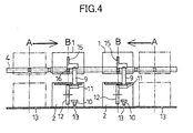
- the positioning groove 16 of the slide guide shaft 4 and the pin hole 13 of the slide guide table 3 are made to correspond to, for example, a binding position A of a sheet of A3 size and a binding position B of a sheet of A4 size, and at respective fixed positions, positions of the driver of the driver unit 1 and the clincher of the clincher unit 2 accurately coincide with each other.
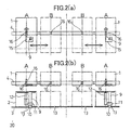
- Fig.3 (a) and Fig.3(b) show a constitution of a stapler traveling mechanism
- the grooved rollers 17, 18 are arranged on a lower side of the slide guide table 3 and on outer sides of both ends of a range of traveling the electric stapler
- the timing belt 19 is hung around the two grooved rollers
- the grooved roller 17 on one side is driven by the motor 20.
- the two clincher units 2 are provided with the arm portions 21 at respective lower faces thereof, in Fig. 3 (a) and Fig. 3 (b) , the arm portion 21 of the left clincher unit 2 is coupled with a depth side of a loop of the timing belt 19 and the arm portion 21 of the right clincher unit 2 is coupled with this side of the loop of the timing belt 19.
- the connecting pin 9 is engaged with a pin hole (not illustrated) of the bottom plate of the driver unit 1 to connect the clincher unit 2 and the driver unit 1, the lever 15 at inside of the driver unit is moved up to release the lever 15 and the slide guide shaft 4 from being engaged, and also the driver unit 1 is brought into a movable state.
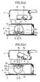
- the connecting pin 9 and the positioning pin 10 are separated from each other, as shown by Fig. 5 (a) and Fig. 5 (b) , the connecting pin 9 and the positioning pin 10 may be integrated by forming a cam follower in a shape of a box by connecting the respective head plates 9a, 10a of the connecting pin 9 and the positioning pin 10.
- the invention is not limited to the above-described embodiments but can variously be modified within the technical range of the invention and the invention naturally includes the modifications.
- the moving mechanism of the electric stapler of the invention is provided with the mechanism of connecting/releasing the clincher unit and the driver unit and therefore, the clincher unit and the driver unit can integrally be moved by the moving mechanism of a wire, a belt or the like arranged only on one side of the clincher unit and the driver unit, and a constitution thereof is more simplified and assembling thereof is more facilitated than those of the moving mechanism of the background art in which wires or belts are arranged on both sides of the clincher unit side and the driver unit side.
- positioning means are provided to both of the clincher unit and the driver unit and therefore, positioning in assemble operation is simple, operability is promoted, a positioning shift is not brought about after assembling, and stability and reliability are also promoted.
Landscapes
- Engineering & Computer Science (AREA)
- Mechanical Engineering (AREA)
- Life Sciences & Earth Sciences (AREA)
- Forests & Forestry (AREA)
- Dovetailed Work, And Nailing Machines And Stapling Machines For Wood (AREA)
- Portable Nailing Machines And Staplers (AREA)
Abstract
Description
Claims (2)
- A moving mechanism of an electric stapler, wherein a driver unit and a clincher unit separately formed from each other are traveled along slide guide members provided in correspondence with the respective units, comprising:wherein the positioning means and the locking means are released from being engaged with each other by connecting the clincher unit and the driver unit by the connecting means, and the positioning means and the locking means are engaged with each other by releasing the clincher unit and the driver unit from being connected with each other by the connecting means.positioning means formed at respectives of the two slide guide members;locking means, provided at respectives of the driver unit and the clincher unit, for engaging with the positioning means; andconnecting means for switching the driver unit and the clincher unit to two states of connecting the driver unit and the clincher unit and releasing the driver unit and the clincher unit from being connected with each other,
- The moving mechanism of an electric stapler according to Claim 1, wherein a motor-driver cam is provided to the clincher unit or the driver unit, and the connecting means and the locking means are integrally driven by the motor-driven cam.
Applications Claiming Priority (3)
| Application Number | Priority Date | Filing Date | Title |
|---|---|---|---|
| JP2002188886A JP4110855B2 (en) | 2002-06-28 | 2002-06-28 | Electric stapler moving mechanism |
| JP2002188886 | 2002-06-28 | ||
| PCT/JP2003/008001 WO2004002696A1 (en) | 2002-06-28 | 2003-06-24 | Moving mechanism for motor-driven staplers |
Publications (3)
| Publication Number | Publication Date |
|---|---|
| EP1518650A1 true EP1518650A1 (en) | 2005-03-30 |
| EP1518650A4 EP1518650A4 (en) | 2005-09-28 |
| EP1518650B1 EP1518650B1 (en) | 2007-03-21 |
Family
ID=29996832
Family Applications (1)
| Application Number | Title | Priority Date | Filing Date |
|---|---|---|---|
| EP03761790A Expired - Lifetime EP1518650B1 (en) | 2002-06-28 | 2003-06-24 | Moving mechanism for motor-driven staplers |
Country Status (6)
| Country | Link |
|---|---|
| US (1) | US7080767B2 (en) |
| EP (1) | EP1518650B1 (en) |
| JP (1) | JP4110855B2 (en) |
| AU (1) | AU2003244183A1 (en) |
| DE (1) | DE60312686T2 (en) |
| WO (1) | WO2004002696A1 (en) |
Cited By (2)
| Publication number | Priority date | Publication date | Assignee | Title |
|---|---|---|---|---|
| EP2127834A1 (en) * | 2008-05-28 | 2009-12-02 | Max Co., Ltd. | Clinch positioning mechansim of stapler |
| EP2338654A3 (en) * | 2009-12-23 | 2013-05-22 | Max Co., Ltd. | Stapler |
Families Citing this family (3)
| Publication number | Priority date | Publication date | Assignee | Title |
|---|---|---|---|---|
| JP4774793B2 (en) * | 2005-04-07 | 2011-09-14 | マックス株式会社 | Electric stapler safety device |
| CN109982810B (en) | 2016-09-23 | 2022-08-30 | 弹性钢接头公司 | Applicator for conveyor belt fasteners |
| US11473649B2 (en) | 2016-09-23 | 2022-10-18 | Flexible Steel Lacing Company | Conveyor belt fastener applicators and fastener beds |
Family Cites Families (14)
| Publication number | Priority date | Publication date | Assignee | Title |
|---|---|---|---|---|
| US4516714A (en) * | 1983-12-21 | 1985-05-14 | Xerox Corporation | High speed duplicator with sorter/stapling apparatus and stapler positioning control |
| US5018656A (en) * | 1987-07-20 | 1991-05-28 | Xerox Corporation | Stapling apparatus |
| DE3839306A1 (en) * | 1988-11-21 | 1990-05-23 | Kodak Ag | DEVICE FOR STACKING AND STAPLING SHEETS |
| JP2703315B2 (en) * | 1989-02-21 | 1998-01-26 | 株式会社リコー | Paper binding device |
| DE4101391C2 (en) | 1991-01-18 | 1995-08-10 | Kodak Ag | Stapling device for sheets |
| DE69313999T2 (en) * | 1992-12-29 | 1998-01-29 | Max Co Ltd | Precision stapler |
| JPH08108377A (en) * | 1994-08-08 | 1996-04-30 | Nisca Corp | Stapler and bookbinding apparatus using the same |
| JP3473233B2 (en) * | 1995-11-16 | 2003-12-02 | ニスカ株式会社 | Stapler |
| JP3473234B2 (en) * | 1995-11-16 | 2003-12-02 | ニスカ株式会社 | Stapler |
| DE19722298A1 (en) * | 1997-05-28 | 1998-12-03 | Eastman Kodak Co | Stacked superimposed sheets binder with enclosed housing |
| JP2000084903A (en) * | 1998-09-11 | 2000-03-28 | Minolta Co Ltd | Staple device |
| US6641024B2 (en) | 2000-02-08 | 2003-11-04 | Nisca Corporation | Stapling device |
| JP4349738B2 (en) * | 2000-10-31 | 2009-10-21 | キヤノンファインテック株式会社 | Sheet processing apparatus and image forming apparatus having the same |
| JP4748293B2 (en) * | 2001-09-11 | 2011-08-17 | マックス株式会社 | Built-in stapler |
-
2002
- 2002-06-28 JP JP2002188886A patent/JP4110855B2/en not_active Expired - Lifetime
-
2003
- 2003-06-24 WO PCT/JP2003/008001 patent/WO2004002696A1/en not_active Ceased
- 2003-06-24 EP EP03761790A patent/EP1518650B1/en not_active Expired - Lifetime
- 2003-06-24 AU AU2003244183A patent/AU2003244183A1/en not_active Abandoned
- 2003-06-24 DE DE60312686T patent/DE60312686T2/en not_active Expired - Lifetime
- 2003-06-24 US US10/519,192 patent/US7080767B2/en not_active Expired - Fee Related
Cited By (5)
| Publication number | Priority date | Publication date | Assignee | Title |
|---|---|---|---|---|
| EP2127834A1 (en) * | 2008-05-28 | 2009-12-02 | Max Co., Ltd. | Clinch positioning mechansim of stapler |
| US7980442B2 (en) | 2008-05-28 | 2011-07-19 | Max Co., Ltd. | Clinch positioning mechanism of stapler |
| CN101590754B (en) * | 2008-05-28 | 2013-07-17 | 美克司株式会社 | Clinch positioning mechanism of stapler |
| EP2338654A3 (en) * | 2009-12-23 | 2013-05-22 | Max Co., Ltd. | Stapler |
| US8523039B2 (en) | 2009-12-23 | 2013-09-03 | Max Co., Ltd. | Stapler |
Also Published As
| Publication number | Publication date |
|---|---|
| DE60312686T2 (en) | 2007-06-28 |
| DE60312686D1 (en) | 2007-05-03 |
| EP1518650B1 (en) | 2007-03-21 |
| EP1518650A4 (en) | 2005-09-28 |
| JP4110855B2 (en) | 2008-07-02 |
| JP2004025765A (en) | 2004-01-29 |
| WO2004002696A1 (en) | 2004-01-08 |
| US20050230452A1 (en) | 2005-10-20 |
| AU2003244183A1 (en) | 2004-01-19 |
| US7080767B2 (en) | 2006-07-25 |
Similar Documents
| Publication | Publication Date | Title |
|---|---|---|
| US7210608B2 (en) | Electric stapler | |
| WO1994000277A1 (en) | Stapler having a clinching mechanism | |
| US20140042203A1 (en) | Fastening device | |
| EP1711314B1 (en) | Stapler | |
| EP0099249B1 (en) | Active clinchers and wire stitchers incorporating same | |
| US8251272B2 (en) | Stapler | |
| EP1518650B1 (en) | Moving mechanism for motor-driven staplers | |
| US7124925B2 (en) | Stapler | |
| EP2127834B1 (en) | Clinch positioning mechansim of stapler | |
| JP2001239470A (en) | Vertical separation type staple sheet post-processing device | |
| US8261957B2 (en) | Locking mechanism for stapler paper presser table | |
| US12138765B2 (en) | Staple removal device | |
| JP2011131444A (en) | Stapler for saddle stitching | |
| JP4852956B2 (en) | Electric stapler | |
| JP2022164105A (en) | stapler | |
| US7621434B2 (en) | Clincher device of stapler | |
| JP4304971B2 (en) | Paper thickness adjustment mechanism in an electric stapler | |
| JPH04129680A (en) | Magazine fixing type motor-driven stapler | |
| JP2003211408A (en) | Electric stapler | |
| CN119217324A (en) | stapler | |
| JPH0663345U (en) | Positioning mechanism for the separate stapler | |
| JP2011183760A (en) | Alignment jig of stapler |
Legal Events
| Date | Code | Title | Description |
|---|---|---|---|
| PUAI | Public reference made under article 153(3) epc to a published international application that has entered the european phase |
Free format text: ORIGINAL CODE: 0009012 |
|
| 17P | Request for examination filed |
Effective date: 20041215 |
|
| AK | Designated contracting states |
Kind code of ref document: A1 Designated state(s): AT BE BG CH CY CZ DE DK EE ES FI FR GB GR HU IE IT LI LU MC NL PT RO SE SI SK TR |
|
| AX | Request for extension of the european patent |
Extension state: AL LT LV MK |
|
| A4 | Supplementary search report drawn up and despatched |
Effective date: 20050818 |
|
| RIC1 | Information provided on ipc code assigned before grant |
Ipc: 7B 27F 7/19 A Ipc: 7B 27F 7/00 B |
|
| DAX | Request for extension of the european patent (deleted) | ||
| RBV | Designated contracting states (corrected) |
Designated state(s): CY DE FR GB NL |
|
| GRAP | Despatch of communication of intention to grant a patent |
Free format text: ORIGINAL CODE: EPIDOSNIGR1 |
|
| RBV | Designated contracting states (corrected) |
Designated state(s): DE FR GB NL SE |
|
| GRAS | Grant fee paid |
Free format text: ORIGINAL CODE: EPIDOSNIGR3 |
|
| GRAA | (expected) grant |
Free format text: ORIGINAL CODE: 0009210 |
|
| AK | Designated contracting states |
Kind code of ref document: B1 Designated state(s): DE FR GB NL SE |
|
| REG | Reference to a national code |
Ref country code: GB Ref legal event code: FG4D |
|
| REF | Corresponds to: |
Ref document number: 60312686 Country of ref document: DE Date of ref document: 20070503 Kind code of ref document: P |
|
| REG | Reference to a national code |
Ref country code: SE Ref legal event code: TRGR |
|
| ET | Fr: translation filed | ||
| PLBE | No opposition filed within time limit |
Free format text: ORIGINAL CODE: 0009261 |
|
| STAA | Information on the status of an ep patent application or granted ep patent |
Free format text: STATUS: NO OPPOSITION FILED WITHIN TIME LIMIT |
|
| 26N | No opposition filed |
Effective date: 20071227 |
|
| REG | Reference to a national code |
Ref country code: FR Ref legal event code: PLFP Year of fee payment: 13 |
|
| PGFP | Annual fee paid to national office [announced via postgrant information from national office to epo] |
Ref country code: SE Payment date: 20150611 Year of fee payment: 13 Ref country code: GB Payment date: 20150624 Year of fee payment: 13 |
|
| PGFP | Annual fee paid to national office [announced via postgrant information from national office to epo] |
Ref country code: FR Payment date: 20150608 Year of fee payment: 13 Ref country code: NL Payment date: 20150510 Year of fee payment: 13 |
|
| REG | Reference to a national code |
Ref country code: SE Ref legal event code: EUG |
|
| REG | Reference to a national code |
Ref country code: NL Ref legal event code: MM Effective date: 20160701 |
|
| PG25 | Lapsed in a contracting state [announced via postgrant information from national office to epo] |
Ref country code: SE Free format text: LAPSE BECAUSE OF NON-PAYMENT OF DUE FEES Effective date: 20160625 |
|
| GBPC | Gb: european patent ceased through non-payment of renewal fee |
Effective date: 20160624 |
|
| REG | Reference to a national code |
Ref country code: FR Ref legal event code: ST Effective date: 20170228 |
|
| PG25 | Lapsed in a contracting state [announced via postgrant information from national office to epo] |
Ref country code: FR Free format text: LAPSE BECAUSE OF NON-PAYMENT OF DUE FEES Effective date: 20160630 |
|
| PG25 | Lapsed in a contracting state [announced via postgrant information from national office to epo] |
Ref country code: NL Free format text: LAPSE BECAUSE OF NON-PAYMENT OF DUE FEES Effective date: 20160701 Ref country code: GB Free format text: LAPSE BECAUSE OF NON-PAYMENT OF DUE FEES Effective date: 20160624 |
|
| PGFP | Annual fee paid to national office [announced via postgrant information from national office to epo] |
Ref country code: DE Payment date: 20170621 Year of fee payment: 15 |
|
| REG | Reference to a national code |
Ref country code: DE Ref legal event code: R119 Ref document number: 60312686 Country of ref document: DE |
|
| PG25 | Lapsed in a contracting state [announced via postgrant information from national office to epo] |
Ref country code: DE Free format text: LAPSE BECAUSE OF NON-PAYMENT OF DUE FEES Effective date: 20190101 |