EP1518529A1 - Transfer device - Google Patents
Transfer device Download PDFInfo
- Publication number
- EP1518529A1 EP1518529A1 EP04255967A EP04255967A EP1518529A1 EP 1518529 A1 EP1518529 A1 EP 1518529A1 EP 04255967 A EP04255967 A EP 04255967A EP 04255967 A EP04255967 A EP 04255967A EP 1518529 A1 EP1518529 A1 EP 1518529A1
- Authority
- EP
- European Patent Office
- Prior art keywords
- endless belt
- transfer device
- belt
- roller
- driving unit
- Prior art date
- Legal status (The legal status is an assumption and is not a legal conclusion. Google has not performed a legal analysis and makes no representation as to the accuracy of the status listed.)
- Granted
Links
- 230000007246 mechanism Effects 0.000 claims abstract description 182
- 230000002093 peripheral effect Effects 0.000 description 12
- 238000001514 detection method Methods 0.000 description 8
- 239000003638 chemical reducing agent Substances 0.000 description 6
- 230000000474 nursing effect Effects 0.000 description 3
- NPNPZTNLOVBDOC-UHFFFAOYSA-N 1,1-difluoroethane Chemical compound CC(F)F NPNPZTNLOVBDOC-UHFFFAOYSA-N 0.000 description 2
- 230000008859 change Effects 0.000 description 2
- 230000001788 irregular Effects 0.000 description 2
- 239000011347 resin Substances 0.000 description 2
- 229920005989 resin Polymers 0.000 description 2
- 206010017577 Gait disturbance Diseases 0.000 description 1
- 238000009499 grossing Methods 0.000 description 1
- 238000001990 intravenous administration Methods 0.000 description 1
- 238000012423 maintenance Methods 0.000 description 1
- 238000004519 manufacturing process Methods 0.000 description 1
- 238000000034 method Methods 0.000 description 1
- 230000002265 prevention Effects 0.000 description 1
- 230000009467 reduction Effects 0.000 description 1
Images


Classifications
-
- A—HUMAN NECESSITIES
- A61—MEDICAL OR VETERINARY SCIENCE; HYGIENE
- A61G—TRANSPORT, PERSONAL CONVEYANCES, OR ACCOMMODATION SPECIALLY ADAPTED FOR PATIENTS OR DISABLED PERSONS; OPERATING TABLES OR CHAIRS; CHAIRS FOR DENTISTRY; FUNERAL DEVICES
- A61G7/00—Beds specially adapted for nursing; Devices for lifting patients or disabled persons
- A61G7/10—Devices for lifting patients or disabled persons, e.g. special adaptations of hoists thereto
- A61G7/1025—Lateral movement of patients, e.g. horizontal transfer
- A61G7/1032—Endless belts
-
- A—HUMAN NECESSITIES
- A61—MEDICAL OR VETERINARY SCIENCE; HYGIENE
- A61G—TRANSPORT, PERSONAL CONVEYANCES, OR ACCOMMODATION SPECIALLY ADAPTED FOR PATIENTS OR DISABLED PERSONS; OPERATING TABLES OR CHAIRS; CHAIRS FOR DENTISTRY; FUNERAL DEVICES
- A61G7/00—Beds specially adapted for nursing; Devices for lifting patients or disabled persons
- A61G7/10—Devices for lifting patients or disabled persons, e.g. special adaptations of hoists thereto
- A61G7/1025—Lateral movement of patients, e.g. horizontal transfer
- A61G7/1036—Lateral movement of patients, e.g. horizontal transfer facilitating loading and unloading of the patient, e.g. using flaps or additional tilting
-
- A—HUMAN NECESSITIES
- A61—MEDICAL OR VETERINARY SCIENCE; HYGIENE
- A61G—TRANSPORT, PERSONAL CONVEYANCES, OR ACCOMMODATION SPECIALLY ADAPTED FOR PATIENTS OR DISABLED PERSONS; OPERATING TABLES OR CHAIRS; CHAIRS FOR DENTISTRY; FUNERAL DEVICES
- A61G7/00—Beds specially adapted for nursing; Devices for lifting patients or disabled persons
- A61G7/10—Devices for lifting patients or disabled persons, e.g. special adaptations of hoists thereto
- A61G7/1063—Safety means
- A61G7/1065—Safety means with electronic monitoring
-
- A—HUMAN NECESSITIES
- A61—MEDICAL OR VETERINARY SCIENCE; HYGIENE
- A61G—TRANSPORT, PERSONAL CONVEYANCES, OR ACCOMMODATION SPECIALLY ADAPTED FOR PATIENTS OR DISABLED PERSONS; OPERATING TABLES OR CHAIRS; CHAIRS FOR DENTISTRY; FUNERAL DEVICES
- A61G2200/00—Information related to the kind of patient or his position
- A61G2200/30—Specific positions of the patient
- A61G2200/32—Specific positions of the patient lying
-
- A—HUMAN NECESSITIES
- A61—MEDICAL OR VETERINARY SCIENCE; HYGIENE
- A61G—TRANSPORT, PERSONAL CONVEYANCES, OR ACCOMMODATION SPECIALLY ADAPTED FOR PATIENTS OR DISABLED PERSONS; OPERATING TABLES OR CHAIRS; CHAIRS FOR DENTISTRY; FUNERAL DEVICES
- A61G7/00—Beds specially adapted for nursing; Devices for lifting patients or disabled persons
- A61G7/10—Devices for lifting patients or disabled persons, e.g. special adaptations of hoists thereto
- A61G7/1001—Devices for lifting patients or disabled persons, e.g. special adaptations of hoists thereto specially adapted for specific applications
- A61G7/1011—Picking up from the floor
Definitions
- the front end of the arm may be provided with a plurality of bracket pieces and a rod supported by the bracket pieces.
- the bracket pieces may be horizontally spaced from each other, and the rod may rotatably support a plurality of belt-reversing rollers for reversing the traveling direction of the second endless belt.
- At least one of the transfer devices may be provided with a sensor for detecting an obj ect below the sensor.
- the output signal from the sensor may be used as a control input signal for the central computer.
- the drive housing 100b of the frame 100A is provided with four idle rollers which include a fourth, a fifth, a sixth and a seventh idle rollers 106, 107, 108, 109 each of which is freely rotatable about an axis extending widthwise between the side frame components 101.
- the fourth idle roller 106 is arranged at a lower portion on the rear side of the drive housing 100b to be generally equal in height to the first, the second and the third idle rollers 103-105, with the peripheral bottom thereof slightly projecting downward from the lower edge of each side frame component 101.
- each of the first, the second and the third rollers 203-205 is located above and spaced from the belt 120 traveling over the first, the second and the third idle rollers 103-105 of the lower mechanism 100.
- each of the rollers 206-209 is freely rotatable about an axis extending widthwise between the side frame components 201.
- the fifth idle roller 207 is vertically movable by a predetermined distance.
- the idle roller 207 is supported by a horizontal shaft. This shaft has two ends (opposite to each other) each of which is received in a vertically elongated hole 210 formed in the side frame component 201. At the respective ends, the support shaft is constantly biased upward by springs 211, so that the idle roller 207 functions as a tension roller.
- the drive housings 100b, 200b of the lower mechanism 100 and the upper mechanism 200 are arranged adjacent to each other in the back and forth direction, and the drive housings 100b, 200b are located at a portion offset toward one end of the assembly in the belt travel direction. Therefore, the drive housings 100b, 200b function as the support of the patient placed on the support 200a of the upper mechanism 100, whereby the patient can be stably held.
Landscapes
- Health & Medical Sciences (AREA)
- Nursing (AREA)
- Life Sciences & Earth Sciences (AREA)
- Animal Behavior & Ethology (AREA)
- General Health & Medical Sciences (AREA)
- Public Health (AREA)
- Veterinary Medicine (AREA)
- Structure Of Belt Conveyors (AREA)
- Invalid Beds And Related Equipment (AREA)
Abstract
Description
- The present invention relates to a transfer device which is suitable for use in transferring a patient between a bed and a stretcher with wheels (gurney) , for example. The transfer device according to the present invention is also suitable for changing the location of e. g. a piece of wooden furniture without damaging it.
- In a hospital, nursing facility or the like, a stretcher is used for transporting a patient who cannot walk or has difficulty in walking from a hospital room to an examination room, a treatment room or a bath, for example. Such a stretcher comprises a rest base having a width and a length sufficient for carrying a patient and supported by legs with wheels at a height generally equal to a bed surface. To transfer the patient between the bed and the stretcher, the stretcher is set alongside the bed.
- The transfer of the patient is generally performed by lifting the sheets on which the patient lies by a plurality of nurses or care workers. Such work is hard, requiring many hands. Moreover, in transferring a patient with a medical instrument such as an intravenous drip device attached to the patient, the transfer work need be performed very carefully. Further, the work for transferring the patient while keeping the posture of the patient so as not to damage the affected part is very difficult and need be performed carefully.
- Conventionally, to facilitate transfer of a patient, various transfer devices have been proposed which utilize motive power to transfer the patient.
- For example, in Japanese patent document JP-B-47-34477, a transfer device is proposed in which a transfer mechanism comprising a lower endless conveyor belt and an upper endless conveyor belt is incorporated in a stretcher for advancement onto a bed and retreat onto the stretcher. In transferring a patient from the bed onto the stretcher, with the stretcher set alongside the bed, the lower endless conveyor belt is driven for travel in one direction, and the transfer mechanism is advanced onto the bed in synchronization with the belt travel speed of the lower endless conveyor belt. At this time, the upper endless conveyor belt is caused to travel in the direction opposite from the lower endless conveyor belt. As a result, the transfer mechanism can slip between the bed surface and the patient for placing the patient on the transfer mechanism (upper endless conveyor belt) without causing relative movement between the lower endless conveyor belt and bed surface and between the upper endless conveyor belt and the patient. Thereafter, with the upper endless conveyor belt stopped, the transfer mechanism is retreated onto the stretcher while the lower endless conveyor belt is caused to travel in the direction opposite from the above, whereby the patient can be transferred onto the stretcher.
- For the conventional transfer device, however, the transfer mechanism is incorporated in the stretcher. Therefore, when the transfer mechanism retreats, the front edge constantly becomes parallel with the stretcher, and there is a limitation on the advance distance of the transfer mechanism, which gives rise to the following problems.
- Firstly, a patient lying as inclined relative to an edge of the bed cannot be properly placed on the transfer mechanism. Specifically, a patient on a bed rarely lies in parallel with an edge of the bed and mostly lies as inclined. Further, depending on the medical condition, the posture of the patient may not be changed easily. In such a case, the transfer device disclosed in the above Patent Document lifts andplace the patient obliquely, so that the posture of the patient on the transfer mechanism becomes unstable. Moreover, even on the stretcher, manual work for putting the patient within the width of the stretcher need be performed. As noted above, depending on the medical condition, such easy posture change of the patient may worsen the condition of the patient.
- Secondly, a patient lying far from the edge of the bed by a distance larger than the width of the stretcher cannot be dealt with. This is because the transfer mechanism advancing from the stretcher set alongside the bed cannot reach the patient. Although a patient whose condition is not severe may be moved manually on the bed, the transfer device cannot deal with a patient who is in critical condition and whose posture cannot be changed easily.
- Moreover, in the transfer device disclosed in the above Patent Document, the transfer mechanism comprising a lower endless conveyor belt and an upper endless conveyor belt vertically combined together is incorporated in the stretcher for advancing and retreating movements. Therefore, the entire apparatus is complicated, and the manufacturing cost is extremely high.
- It is, therefore, an object of the present invention to provide a transfer device which is capable of solving the above problems of the prior art structure, with a simple structure which contributes to cost reduction. The transfer device of the present invention is capable of transferring e.g. a patient to a stretcher regardless of the position and posture of the patient on the bed.
- According to a first aspect of the present invention, there is provided a transfer device comprising: a lower mechanism including a first endless belt and a first driving unit for operating the first endless belt; and an upper mechanism including a second endless belt and a second driving unit for operating the second endless belt. The upper mechanism is stacked on the lower mechanism. The first endless belt and the second endless belt are operable independently of each other for forward and backward circulation. The first driving unit is disposed at one end of the lower mechanism as viewed in a traveling direction of the first endless belt, while the second driving unit is disposed at one end of the upper mechanism as viewed in a traveling direction of the second endless belt. The first and the second driving units may be disposed adjacent to each other.
- With such an arrangement, in each of the lower and the upper mechanisms, the remaining portion (patient-supporting portion) except for the driving unit can be small in height, which ensures easy and comfortable transfer of a patient from a stretcher to a bed, or a bed to a stretcher, for example.
- Preferably, the lower mechanism may include a first rectangular frame and a plurality of first rollers rotatably supported by the first frame, the first endless belt being guided in circulation by these first rollers. Likewise, the upper mechanism may include a second rectangular frame and a plurality of second rollers rotatably supported by the second frame, the second endless belt being guided in circulation by these second rollers.
- Preferably, the lower mechanism may include a first supporting section extending horizontally from the first driving unit and having a smaller height than the first driving unit, the first driving unit including a first driving roller held in contact with the first endless belt. Likewise, the upper mechanism may include a second supporting section extending horizontally from the second driving unit and having a smaller height than the second driving unit, the second driving unit including a second driving roller held in contact with the second endless belt.
- Preferably, each of the first endless belt and the second endless belt may include a smooth inner surface and an outer surface which is less smooth than the inner surface. In this case, the first driving roller is held in contact with the outer surface of the first endless belt, and the second driving roller is held in contact with the outer surface of the second endless belt. In this manner, the driving force is efficiently transmitted to the endless belt from the driving roller.
- Preferably, the first driving unit may be provided with a first tension roller held in contact with the first endless belt, while the second driving unit may be provided with a second tension roller held in contact with the second endless belt. With such an arrangement, the driving force from e.g., a motor can be more efficiently transmitted to the endless belt.
- Preferably, each of the first endless belt and the second endless belt may be a timing belt. In this case, the tension rollers may not be necessary.
- Preferably, the upper mechanism may include an arm extending beyond the lower mechanism. The arm may have a front end provided with at least one belt-reversing roller for reversing a traveling direction of the second endless belt.
- Preferably, the belt-reversing roller may be disposed at a lower position than the first rollers.
- Preferably, the arm may be pivotable about a horizontal axis and constantly urged downward.
- Preferably, the arm may be provided with a sled covering a lower portion of the belt-reversing roller. With such an arrangement, it is possible to prevent the running endless belt of the upper mechanism from coming into contact with e.g. the sheet on the bed.
- Preferably, the front end of the arm may be provided with a plurality of bracket pieces and a rod supported by the bracket pieces. The bracket pieces may be horizontally spaced from each other, and the rod may rotatably support a plurality of belt-reversing rollers for reversing the traveling direction of the second endless belt.
- Preferably, the upper mechanism may be detachably attached to the lower mechanism for enabling easier maintenance of the two mechanisms.
- According to a second aspect of the present invention, there is provided a transfer device assembly comprising a plurality of transfer devices according to the first aspect of the present invention. In the assembly, the plurality of transfer devices are connected to each other in a widthwise direction, and the first endless belts of the respective transfer devices are operable independently of each other for forward and backward circulation.
- Preferably, the lower mechanisms of the respective transfer devices may be connected to each other for providing a lower mechanism assembly to which each of the upper mechanisms is detachably attached.
- Preferably, each of the first driving units and the second driving units of the respective transfer devices may be provided with a driving roller held in contact with the endless belt, a motor for rotating the driving roller, a motor driver for operating the motor, and an individual computer for controlling the motor driver. The individual computer may be controlled by a central computer.
- Preferably, each of the transfer devices may be provided with a power supply battery.
- In the transfer device assembly of the second aspect, each transfer device has its width adjusted in a manner such that the total width of the combined transfer devices (i.e., the transfer device assembly) corresponds to the height of a patient or to the length of the bed.
- Preferably, at least one of the transfer devices may be provided with a sensor for detecting an obj ect below the sensor. The output signal from the sensor may be used as a control input signal for the central computer. With such an arrangement, it is possible to automatically stop the traveling assembly when there is no supporting surface ahead of the assembly. Thus, the assembly is prevented from falling off the bed or the stretcher by accident.
- Preferably, at least one of the transfer devices may be provided with a speaker controlled by the central computer. Through the speaker, the human operator can be provided with audio information about the operating conditions of the assembly and operational instructions helpful for the operator to properly operate the transfer device assembly.
- Other features and advantages of the present invention will become clearer from the detailed description given below with reference to the accompanying drawings.
- Preferred embodiments of the present invention will now be described by way of example only with reference to the accompanying drawings, in which:
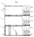
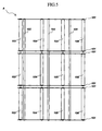
- Fig. 1 is a plan view which is partially cut away, showing a transfer device assembly according to a first embodiment of the present invention;
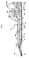
- Fig. 2 is a sectional view taken along lines II-II in Fig. 1;
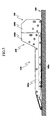
- Fig. 3 is a side view of the transfer device assembly shown in Fig. 1;
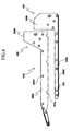
- Fig. 4 is a side view showing an assembling manner of the transfer device assembly shown in Fig. 1;
- Fig. 5 is a bottom view showing the frame of a lower mechanism of the transfer device shown in Fig. 1, with the back-up plates omitted;
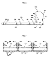
- Fig. 6 is a side view of the lower mechanism of the transfer device assembly shown in Fig. 1;
- Fig. 7 schematically illustrates the rear surface of the lower mechanisms of the transfer device assembly shown in Fig. 1, with components such as the endless belts omitted;
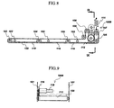
- Fig. 8 is a sectional view taken along lines VIII-VIII in Fig. 7;
- Fig. 9 is a view taken along lines IX-IX in Fig. 8;
- Fig. 10 is a side view of the upper mechanism of the transfer device assembly shown in Fig. 1;
- Fig. 11 schematically illustrates the rear surface of the upper mechanism of the transfer device assembly shown in Fig. 1, with components such as the endless belts omitted;
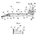
- Fig. 12 is a sectional view taken along lines XII-XII in Fig. 11;
- Fig. 13 is a sectional view taken along lines XIII-XIII in Fig. 12;
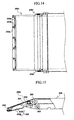
- Fig. 14 is an enlarged plan view showing a pivot arm of the upper mechanism.
- Fig. 15 is a sectional side view, partially in section, showing the pivot arm of the upper mechanism;
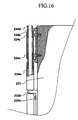
- Fig. 16 is an enlarged plan view, partially in section, showing details of the support structure of a belt reversing roller in the pivot arm of the upper mechanism;
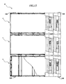
- Fig. 17 is a plan view, partially in section, showing respective driving portions of the upper mechanisms and the lower mechanisms;
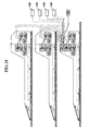
- Fig. 18 schematically illustrates the electrical system of the transfer device assembly shown in Fig. 1;
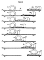
- Fig. 19 shows an example of transferring manner using the transfer device assembly shown in Fig. 1;
- Fig. 20 shows an example of transferring manner using the transfer device assembly shown in Fig. 1;
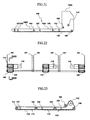
- Fig. 21 is a side view showing another embodiment of the present invention;
- Fig. 22 schematically illustrates the rear surface of the lower mechanisms shown in Fig. 21; and
- Fig. 23 is a sectional view taken along lines XXIII-XXIII in Fig. 22.
-
- Reference is now made to the accompanying drawings for describing the preferred embodiments of the present invention.
- Figs. 1-18 show a first embodiment of transfer device assembly according to the present invention.
- As shown in Fig. 1, the transfer device assembly A comprises a plurality of
transfer devices 1 connected together in the widthwise direction. In the illustrated embodiment, three transfer devices are connected together. The width of the transfer device assembly A is so selected as to be sufficient for carrying a patient on a bed, and hence the width of eachtransfer device 1 is determined depending on the selected width of the assembly. As shown in Figs. 2-4, eachtransfer device 1 includes alower mechanism 100 and anupper mechanism 200 stacked together in the vertical direction. - The
upper mechanism 100 and thelower mechanism 200 of each transfer device includeendless belts portions endless belts lower mechanism 100 and theupper mechanism 200 at one end in the belt travel direction. This point will be described in detail below. - As shown in Figs. 5-8, the
lower mechanism 100 includes aframe 100A comprising a pair ofside frame components 101 and a plurality ofcross frame components 102 bridging the pairedside frame components 101. Theframe 100A includes ahorizontal support 100a having a uniform height and a predetermined horizontal length, and adrive housing 100b which is provided at an end of thesupport 100a and is larger in height than thesupport 100a. Hereinafter, thesupport 100a side of theframe 100A is defined as the front side, whereas thedrive housing 100b side of theframe 100A is defined as the rear side. The height of thesupport 100a and the height of thedrive housing 100b are defined by the vertical dimension of theside frame components 101. - The
support 100a of theframe 100A is provided with three idle rollers which include a first, a second and a thirdidle rollers side frame components 101. Preferably, each of the idle rollers 103-105 has a minimum diameter which allows the rotation of the roller without difficulty, and the opposite ends of the idle rollers are supported by theside frame components 101. Each of the idle rollers 103-15 is so supported that the peripheral bottom thereof slightly projects downward from the lower edge of eachside frame component 101. - The
drive housing 100b of theframe 100A is provided with four idle rollers which include a fourth, a fifth, a sixth and a seventhidle rollers side frame components 101. Among these rollers, the fourthidle roller 106 is arranged at a lower portion on the rear side of thedrive housing 100b to be generally equal in height to the first, the second and the third idle rollers 103-105, with the peripheral bottom thereof slightly projecting downward from the lower edge of eachside frame component 101. The fifthidle roller 107, which is arranged above the fourthidle roller 106, is movable vertically within a predetermined distance, with the opposite ends of its support shaft received in vertically elongated support holes 110 formed in theside frame components 101, and constantly biased upward bysprings 111. As will be described later, the fifthidle roller 107 functions as a tension roller. The sixthidle roller 108 is located ahead of the fifthidle roller 107 while being spaced therefrom by a predetermined distance. The seventhidle roller 109 is located ahead of the sixthidle roller 106. The peripheral bottom of theseventh roller 109 is generally flush with the peripheral top of each of the first, the second and the third idle rollers 103-105. - The
drive housing 100b of theframe 100A is further provided with adrive roller 112 which is arranged below and between the fifth and the sixthidle rollers side frame components 101. As shown in Fig. 9, amotor 118 with a speed reducer (not shown) is provided in thedrive housing 100b of theframe 100A via abracket 116. By transmitting the rotation of themotor 118 to thedrive roller 112 via a plurality of gears (not shown) , thedrive roller 112 is driven for rotation selectively in opposite directions. - The
endless belt 120, which has a width corresponding to the spacing between theside frame components 101, is wound around the idle rollers 103-109 and thedrive roller 112. In thesupport 100a of theframe 100A, thebelt 120 is supported by the peripheral top of each of the first, the second, the third idle rollers 103-105 and turns around the firstidle roller 103 to change the extending direction. Then, the belt extends under the first, the second, the third idle rollers 103-105. In thedrive housing 100b of theframe 100A, thebelt 120 turns around the fourthidle roller 106 to extend upward, turns around the fifth idle roller (tension roller) 107 to extend downward, and then turns around thedrive roller 112 with the outer surface of the belt held in contact with the drive roller. After passing around thedrive roller 112, the belt turns around the sixthidle roller 108 and the seventhidle roller 109 and then extends into thesupport 100a of theframe 100. In this way, by rotating thedrive roller 112 selectively in opposite directions, theendless belt 120 circulates along the above-described travel path selectively in either one of the two opposite directions. In traveling under the first, the second, the third, the fourth idle rollers 103-106, the inner surface of thebelt 120 is slidably supported by back-up plates 119 (Fig. 8) provided to bridge between theside frame components 101. - Preferably, the inner surface of the
endless belt 120 is treated with e.g. ethylene fluoride resin for enabling smooth sliding movement, whereas the outer surface of the endless belt is treated to become irregular to provide slip resistance. In thesupport 100a of theframe 100A, thebelt 120 contacts both of the peripheral top and peripheral bottom of each of the first, the second and the third idle rollers 103-105. The above-described treatment of the inner surface of thebelt 120 prevents the traveling of the belt from being hindered due to the resistance by contact with the idle rollers 103-105. On the other hand, since the outer surface of thebelt 120 is made slip-resistant with respect to thedrive roller 112 , the rotation force of theroller 112 is efficiently transmitted to thebelt 120, whereby thebelt 120 is driven without slipping. As described later, the slip-resistant outer surface of thebelt 120 comes into contact with abed surface 300, for example, the traveling force of thelower mechanism 100 by the rotation of thebelt 120 is efficiently transmitted to thebed surface 300. - As shown in Fig. 5, each
cross frame component 102 extends through theside frame components 101 of the respectivelower mechanisms 100. Thus, the threelower mechanisms 100 are connected widthwise to each other as one integral assembly. - The
upper mechanism 200 has a structure which is similar to the above-described structure of thelower mechanism 100. Specifically, as shown in Figs. 10-13, theupper mechanism 200 includes aframe 200A comprising a pair ofside frame components 201 and a plurality of non-illustrated cross frame components bridging the pairedside frame components 201. Theframe 200A includes asupport 200a having a uniform height and a predetermined horizontal length, and adrive housing 200b which is provided at an end of thesupport 200a and is larger in height than thesupport 200a. The distance between theside frame components 201 of theupper mechanism 200 corresponds to the distance between the outer surfaces of theside frame components 101 of thelower mechanism 100. Eachside frame component 201 of theupper mechanism 200 has a lower edge formed with recesses orcutouts 201a. Therecesses 201a correspond in position to thecross frame components 102 of thelower frame 100A so that eachrecess 201a can come into engagement with the corresponding one of thecross frame components 102 from above. As shown in Figs. 2-4, theupper mechanism 200 is stacked on and combined with thelower mechanism 100 with therecesses 201a held in engagement with thecross frame components 102. As shown in Figs. 2 and 3, when theupper mechanism 200 is combined with thelower mechanism 100, thedrive housing 200b of theframe 200A of theupper mechanism 200 is located in front of thedrive housing 100b of theframe 100A of thelower mechanism 100. Thesupport 200a of theframe 200A of theupper mechanism 200 proj ects forward beyond the front end of thesupport 100a of theframe 100A of thelower mechanism 100. - The
support 200a of theframe 200A of theupper mechanism 200 is provided with three idle rollers which are a first, a second and a thirdidle rollers side frame components 201. Each of the idle rollers 203-205 has a diameter which is as small as possible and generally equal to those of the first, the second, the third idle rollers 103-105 of thelower mechanism 100. The height of each of the first, the second and the third idle rollers 203-205 is so set that the peripheral top of the roller becomes flush with the upper edge of thesupport 200a of theside frame components 201. The lower edge of each of the first, the second and the third rollers 203-205 is located above and spaced from thebelt 120 traveling over the first, the second and the third idle rollers 103-105 of thelower mechanism 100. With such an arrangement, as described later, anendless belt 220 traveling around the rollers in theupper mechanism 200 is prevented from coming into contact with theendless belt 120 of thelower mechanism 100. - In the
drive housing 200b of theframe 200A, four idle rollers, i.e. a fourth, a fifth, a sixth and a seventh idle rollers 206-209 are provided in a manner similar to that of the four idle rollers 106-109 of thelower mechanism 100. For instance, each of the rollers 206-209 is freely rotatable about an axis extending widthwise between theside frame components 201. The fifthidle roller 207 is vertically movable by a predetermined distance. Specifically, theidle roller 207 is supported by a horizontal shaft. This shaft has two ends (opposite to each other) each of which is received in a verticallyelongated hole 210 formed in theside frame component 201. At the respective ends, the support shaft is constantly biased upward bysprings 211, so that theidle roller 207 functions as a tension roller. - In the
upper mechanism 200 again, thedrive housing 200b of theframe 200A is provided with adrive roller 212 arranged between and below the fifth and the sixth idle rollers 207-208 to be rotatable about an axis extending widthwise between theside frame components 201. Similarly to thelower mechanism 100, amotor 218 with a speed reducer is provided in thedrive housing 200b of theframe 200A via a bracket 216 (Fig. 13). By transmitting the rotation of themotor 218 to thedrive roller 212 via a plurality of gears, thedrive roller 212 is driven for rotation in any one of the two opposite directions. - As shown in Figs. 12, 14-15, the
support 200a of theframe 200A of theupper mechanism 200 has a front end provided with apivot arm 200c which is vertically pivotable about a widthwise-extendingshaft 230. Thepivot arm 200c is constantly biased downward bytorsion springs 230c. The pivot arm200c has a front end provided with a rotatable, belt-reversingroller 234 having a relatively small diameter. - As shown in Figs. 14 and 15, the
pivot arm 200c includes a plate-like arm member 231 pivotable about theshaft 230. Thearm member 231 has a front surface to which a plurality of rod-supportingprojections ("bracketpieces") 233bareattached. Eachprojection 233b extends forward from the front surface of thearm member 231. In the illustrated example, use is made of sixprojections 233b divided into three identical units (each including twoprojections 233b). In each unit, the twoprojections 233b are connected to each other by abase plate 233a extending between them (the pairedprojections 233b and thebase plate 233a constitutes one bracket). Thebase plate 233a is fixed to the front surface of thearm member 231 by bolts, for example. - As shown in Fig. 16, the
bracket pieces 233b support arod 234b extending widthwise of theframe 200A. Therod 234b is provided with a plurality of small-diameter rollers 234a each located between adjacent ones of thebracket pieces 233b and rotatably fitted around the rod. In this manner, therollers 234a spaced widthwise of theframe 200A constitute a belt reversingroller assembly 234. With such an arrangement, eachroller 234a has a relatively small length. Thus, even when therod 234b has a relatively small diameter (and accordingly eachroller 234a has a small outer diameter, say, 5mm), theroller 234a can properly rotate on therod 234b without sticking to the rod or causing stick-slip movement, for example. Preferably, theroller 234a may comprise a cylindrical member andoilless bushes 234c fitted at the two ends of the cylindrical member for reducing friction. - The
support 200a of theframe 200A of theupper mechanism 200 is provided with a plurality of back-upplates 219 for slidably supporting the inner surface of theendless belt 220. The back-upplates 219 are disposed between the firstidle roller 203 and the secondidle roller 204, and between the secondidle roller 204 and the thirdidle roller 205. Thesupport 200a is also provided with aguide roller 202 located below the firstidle roller 203 for supporting theendless belt 220 from below. Further, thepivot arm 200c is provided with asled 232 covering the lower side of theroller assembly 234. Thesled 232 comprises twobrackets 232a and asled plate 232b. Thebrackets 232a are connected to the right and left sides of thearm member 231, while thesled plate 232b bridges between thebrackets 232a and are connected to them. Thesled plate 232b, extending forward under thearm member 231, has a front end which is located under theroller assembly 234 and spaced therefrom by a predetermined distance. This front end is curved upward (downwardly convex) to follow the contour of theroller assembly 234. - The
endless belt 220 has a width corresponding to the dimension between theside frame components 201. As shown in Figs. 1, 2 and 12, theendless belt 220 is wound around the idle rollers 203-209, thedrive roller 212, theroller assembly 234 and theguide roller 202. In thesupport 200a of theframe 200A and thepivot arm 200c, thebelt 220 is supported by the peripheral top of the idle rollers 203-205 and caused to turn around by theroller assembly 234, so that the travel direction of thebelt 220 is reversed. Then, thebelt 220 is supported by theguide roller 202 from below and extends under the peripheral bottom of the idle rollers 203-205. In thedrive housing 200b of theframe 200A, thebelt 220 turns around the fourthidle roller 206 to extends upward, turns around the fifth idle roller (tension roller) 207 to travel downward. Then, thebelt 220 turns around thedrive roller 212 with the outer surface of the belt held in contact with the drive roller. After separating from thedrive roller 212, thebelt 220 turns around the sixth and seventhidle rollers support 200a of theframe 200. With such an arrangement, upon rotation of thedrive roller 212 in a selected one of the forward and backward directions, theendless belt 220 is caused to travel along the above-described travel path in the desired direction. In traveling along the upper surface of thepivot arm 200c, thebelt 220 is slidably supported by thearm member 231. Further, in travelling along the upper surface of thesupport 200a of theframe 200A, thebelt 220 is slidably supported by the back-upplates 219. Under the rollerassembly234, theendless belt 220 is protectively covered by thesled 232. - Preferably, the
endless belt 220 of theupper mechanism 200 alsohas its inner surface treatedwithe.g. ethylene fluoride resin for enabling smooth sliding movement and has its outer surface treated to become irregular to prevent slipping. In thesupport 200a of theframe 200A, thebelt 220 contacts both of the peripheral tops and peripheral bottoms of the first, the second and the third idle rollers 203-205. The above smoothing treatment of the inner surface of thebelt 220 prevents improper traveling of the belt. On the other hand, since the anti-slipping outer surface of thebelt 220 coming into contact with thedrive roller 212 ensures that the rotational force of theroller 212 is efficiently transmitted to thebelt 220, whereby thebelt 220 can travel without slipping. Accordingly, as described in detail below, a patient can be moved onto thesupport 200a of theframe 200A of theupper mechanism 200 without causing the slipping of thebelt 220. - According to the present invention, as noted above, the tree
lower mechanism 100 combined bycross frame components 102 constitute a lower mechanism assembly, upon which the above-describedupper mechanisms 200 are stacked, oneupper mechanism 200 for onelower mechanism 100. This provides a transfer device assembly A comprising threetransfer devices 1 connected to each other in their widthwise direction. - As noted above, the
lower mechanism 100 and theupper mechanism 200 of eachtransfer device 1 are provided withindividual driving portions motors motors upper mechanism 200 of eachtransfer device 1 has a battery Ba which supplies electric power to thelower mechanism 100 and theupper mechanism 200 of thetransfer device 1. A central computer CC is mounted in a selected one of the threetransfer devices 1. The micro computers MC mounted in thelower mechanism 100 and theupper mechanism 200 of eachtransfer device 1 are controlled by the central computer CC. The central computer CC receives instructions of a human operator through a control box CB arranged at an appropriate portion of the transfer device assembly A. Preferably, each of the central computer CC and micro computers MC comprises a one-chip computer. - Asnotedabove, the transfer device assemblyAis so designed as to reduce the travel resistance of the
endless belts transfer device 1 and also to efficiently transmit the driving force to thebelts motors portions lower mechanism 100 and theupper mechanism 200 in eachtransfer device 1. - As shown in Fig. 17, a plurality of obj
ect detection sensors 130 for optically detecting the presence (and absence) of an object below (the floor or any other supporting surface, for example) may be provided at the four corners of the transfer device assembly A. Theobject detection sensor 130 outputs an ON signal when an object exists within a predetermined vertical range under the sensor, while it outputs an OFF signal when there is no such object. The output signals from theobject detection sensor 130 are utilized as part of input signals for the control by the central computer CC. With such an arrangement, the transfer device assembly A can be designed to automatically stop in the traveling when there is an OFF signal output, which means that no surface for supporting the assembly A is present ahead. In other words, thedetection sensors 130 and the related system serve as fall prevention means for the assembly A. - Further, as shown in Fig. 18, the transfer device assembly A may be provided with a speaker SP controlled by the central computer CC. With such an arrangement, the human operator can hear , for example, the explanation about the current operation of the apparatus or instructions the operator needs to follow. For example, by notifying operational instructions by voice, a nurse or a care worker in operating the transfer device assembly can notice that some erroneous operation is being performed. This enables him or her to swiftly take care of the trouble (stop the operation, for example), and therefore the safety can be enhanced. As another example, when the object detection sensor detects the absence of an object below (the supporting surface) and the apparatus is automatically stopped, the reason for the halt can be notified through the speaker SP.
- In the transfer device assembly A, the entire apparatus can be advanced or retreated by driving the
endless belt 120 of eachlower mechanism 100. Further, since thelower mechanism 100 and theupper mechanism 200 of eachtransfer device 1 haveindependent driving portions - Specifically, for the "straight traveling" mode, all of the
endless belts 120 of thelower mechanisms 100 of the threetransfer devices 1 are operated in the same direction at the same speed. In this "straight travelling", selection can be made between a first mode in which theendless belts 220 of theupper mechanisms 200 rotate in the opposite direction from theendless belts 120 of thelower mechanisms 100 and a second mode in which theendless belts 220 of theupper mechanisms 200 are kept stationary. - For the "circular traveling", the
endless belt 120 of the left-sidelower mechanism 100 and theendless belt 120 of the right-sidelower mechanism 100 are operated at different speeds. Theendless belt 120 of thelower mechanism 100 in the middle is operated at the average speed of the rotation speeds of theendless belts 120 of the left and the rightlower mechanisms 100. In this case, theendless belt 220 of eachupper mechanism 200 may be kept stationary. - In the "turning at a fixed position", the
endless belt 120 of the left-sidelower mechanism 100 and theendless belt 120 of the right-sidelower mechanism 100 are operated in the opposite directions, whereas theendless belt 120 of the centerlower mechanism 100 is kept stationary. In this case, theendless belt 220 of eachupper mechanism 200 may be kept stationary. - In the "patient-carried turning", the
endless belt 120 of the left-sideupper mechanism 200 and theendless belt 220 of the right-sideupper mechanism 200 are operated in the opposite directions, whereas the endless belt of theupper mechanism 200 in the middle is kept stationary. In this case, theendless belt 120 of eachlower mechanism 100 may be kept stationary. - The control box CB may be provided with an ON/OFF switch as well as switches for selecting the above-described mode such as "straight traveling" "circular traveling" "turning at a fixed position" or "patient-carried turning" and for selecting the direction and the speed in each mode. In accordance with such an operation input, the central computer CC transmits instructions to each micro computer MC, whereby each
motor object detection sensors 130 are also sent to the central computer CC so that the driving of theendless belts 120 of all thelower mechanisms 100 is stopped when any one of theobject detection sensors 130 detects the absence of an object below and outputs an OFF signal. - Next, the basic operation of the transfer device assembly A will be described below with reference to Fig 2, for example. The transfer device assembly A is placed on a stretcher or on a bed. Therefore, the lower traveling portion of the
endless belt 120 of thelower mechanism 100 comes into contact with thebed surface 300, for example. Since thesupport 200a of theupper mechanism 200 projects forward of thesupport 100a of thelower mechanism 100 and thepivot arm 200c is resiliently biased downward, thesled 232 at the front end of thepivot arm 200c also resiliently contacts thebed surface 300. When theendless belt 120 of thelower mechanism 100 is rotated selectively in opposite directions, theendless belt 120 moves like a caterpillar, whereby the transfer device assembly A as a whole advances or retreats. At this time, thepivot arm 200c slides over thebed surface 300 via thesled 232 so that theendless belt 220 turning around theroller assembly 234 does not come into direct contact with thebed surface 300. Therefore, the movement of theendless belt 220 of theupper mechanism 200 does not hinder the advance or retreat of the transfer device assembly A nor roll up the sheets or clothes of the patient. - In the case where the
endless belt 120 of thelower mechanism 100 is driven for rotation (in the direction of the arrow p in Fig. 2) for advancing the apparatus, when theendless belt 220 of theupper mechanism 200 is rotated at the same speed but in the opposite direction from theendless belt 120 of thelower mechanism 100, the movement of theendless belt 220 traveling along the upper surface of thesupport 200a of theupper mechanism 200 relative to thebed surface 300 does not occur. Therefore, thesupport 200a of theupper mechanism 200 of the transfer device assembly A can slip between thebed surface 300 and the patient lying on the bed without putting stress on the patient. This means that the patient on the bed can be smoothly transferred onto thesupport 200a of theupper mechanism 200 of the transfer device assembly A. The load of the patient moving from theroller assembly 234 along thepivot arm 200c while being carried by thebelt 220 is substantially supported by the plate-like arm member 231. The load of the patient carried by the belt in thesupport 200a of theupper mechanism 200 is substantially supported by the back-upplates 219. In thetransfer device 1, the height of thesupports lower mechanism 100 and theupper mechanism 200 is reduced, and the diameter of theroller assembly 234 is made relatively small. Therefore, the discomfort or fear the patient feels when he or she is transferred from the bed onto thetransfer device 1 can be reduced. Further, as noted above, thebelts portions drive motors bed surface 300 without slipping, and the patient can be placed on thesupport 200a without slipping. The above-described is the operation for placing the patient onto thesupport 200a of theupper mechanism 200 by slipping thetransfer device 1 between thebed surface 300 and the patient. To transfer the patient from thesupport 200a of theupper mechanism 200 to thebed surface 300, the assembly is operated in the opposite manner. Specifically, in the state in which the patient is placed on thesupport 200a, theendless belts lower mechanism 100 and theupper mechanism 200 are operated in the direction of the arrow q. By this, the transfer device assembly A can move sideways from between the patient and thebed surface 300 without causing relative movement between the patient and thebed surface 300. - Further, by rotating the
endless belt 120 of thelower mechanism 100 respectively in the opposite directions with theendless belt 220 of theupper mechanism 200 kept stationary, the transfer device assembly A can advance or retreat while carrying the patient. - In the transfer device assemblyA, the
drive housings lower mechanism 100 and theupper mechanism 200 are arranged adjacent to each other in the back and forth direction, and thedrive housings drive housings support 200a of theupper mechanism 100, whereby the patient can be stably held. - Next, with reference to Figs. 19 and 20, an example of manner for transferring e.g. a patient by the transfer device assembly A will be described in detail. Fig. 19 shows an example of transferring a patient 20 from a
bed 30 in e.g. a hospital room as the pre-transfer position onto astretcher 40, whereas Fig. 20 shows an example of transferring a patient 20 from thestretcher 40 onto abed 30 in a treatment room such as an operation room as the transfer destination. - As shown in Fig. 19(a), the transfer device assembly A is placed on the
stretcher 40. The transfer device assembly A is held on thestretcher 40 with thesupport 200a oriented toward thebed 30 as the pre-transfer position and fixed, in this state, to a side of thebed 30 by a non-illustrated engagement unit (Fig. 19(b)). Thepatient 20 is lying on thebed 30. - The transfer device assembly A is caused to perform "straight traveling". As a result, the transfer device assembly A travels from the
stretcher 40 onto the bed 30 (Fig. 19(c)) to come close to thepatient 20. When the patient 20 lies as inclined, the assembly performs "circular traveling" in either direction so that the front edge of the transfer device assembly A becomes substantially parallel to the patient. - Subsequently, the transfer device assembly A is caused to perform "straight traveling" by a predetermined distance while the
endless belts 220 of theupper mechanisms 200 are rotated at the same speed but in the opposite direction from theendless belts 120 of thelower mechanisms 100. As a result, the patient 20 can be placed on thesupport 200a of the transfer device assembly A without causing relative movement between the patient 20 and the bed surface 300 (Fig. 19(d)(e)). - Subsequently, with the
endless belts 220 of theupper mechanisms 200 kept stationary, theendless belts 120 of thelower mechanisms 100 are rotated in the opposite direction from the above, whereby the transfer device assembly A is caused to perform "straight traveling" in the retreating direction (Fig. 19(f)). When thepatient 200 who has lay as inclined is placed, "circular traveling" is performed so that the transfer device assembly A becomes parallel with the length of thebed 30. As a result, with the patient 20 placed on thesupport 200a, the transfer device assembly A moves onto the stretcher 40 (Fig. 19(g)). When the transfer device assembly A is completely moved onto thestretcher 40, the engagement between thestretcher 40 and thebed 30 is released so that thestretcher 40 is moved to a predetermined place such as an operating room in a hospital or nursing facility (Fig. 19(h)). - When the patient has moved and inclined after the placement onto the
support 200a, thebelts 220 of theupper mechanisms 200 of thetransfer devices 1 are operated individually to perform the above-described"patient-carried turning",whereby the posture of the patient is adjusted to become parallel with the edge of the transfer device assembly A. - As shown in Fig. 20 (a) (b), the
stretcher 40 on which the transfer device assembly A carrying the patient 20 on thesupport 200a is placed is set alongside and fixed to thebed 30 such as a bed in an operating room as the transfer destination. In this case again, the transfer device assembly A is so set that thesupport 200a is oriented toward thebed 30 as the transfer destination. - With the
endless belts 220 of theupper mechanisms 200 kept stationary, the transfer device assembly A is caused to perform "straight traveling" in the advancing direction and moves onto thebed 30 as the transfer destination (Fig. 20 (c) (d) ) . - Subsequently, the transfer device assembly A is caused to perform "straight traveling" in the retreating direction. At this time, the
endless belts 220 of theupper mechanisms 200 are rotated at the same speed but in the opposite direction from theendless belts 120 of thelower mechanisms 100. As a result, the transfer device assembly A moves sideways to get out from between the patient 20 and the bed surface 300 (Fig. 20(e)(f)). At this time, as noted above, relative movement does not occur between theendless belts 220 of theupper mechanisms 200 and thebed surface 300, so that the patient 20 can be transferred from thesupport 200a onto thebed 30 as the transfer destination without feeling much discomfort. - The transfer device assembly A continues the "straight traveling" in the retreating direction and returned onto the stretcher 40 (Fig. 20 (g) ) . After the transfer device assembly A is completely moved onto the
stretcher 40, the engagement between thestretcher 40 and thebed 30 of the transfer destination is released, whereby thestretcher 40 and the transfer device assembly A placed thereon is removed from thebed 30 of the transfer destination (Fig. 20(h)). - When the
bed 30 of the pre-transfer position or the transfer destination has a width corresponding to the length of the transfer device assembly A, the transfer device assembly may be turned around by performing the above-described "turning at a fixed position". - As noted above, the above operation of the transfer device assembly A is performed by the operation of the switches of the control box CB by a nurse or a care worker. As noted above, when part of the transfer device assembly A protrudes from the
bed 30 or thestretcher 40, any one of theobject detection sensors 130 outputs an OFF signal. In accordance with the signal, the central computer CC stops the operation of thelower mechanisms 100, whereby the transfer device assembly A is prevented from falling from thebed 30 or thestretcher 40. - Each of the
transfer devices 1 of the transfer device assembly A incorporates the battery Ba. Therefore, when the patient transferred from thebed 30 of the pre-transfer position onto thestretcher 40 in a hospital room is moved to a treatment room such as an operating room and transferred onto thebed 30 as the transfer destination, an AC power source is not necessary. Therefore, the transferring operation can be performed quickly, and the transfer area can be greatly increased. - Figs. 21-23 show a second embodiment of
lower mechanism 100 of the transfer device assembly A according to the present invention. - The
lower mechanism 100 of this embodiment differs from that of the first embodiment in the structure of theendless belt 120 and the drivingportion 100B for rotating the belt. Specifically, in this embodiment, a timing belt (toothed belt) having a width which is smaller than that of theframe 100A is used as theendless belt 120 of thelower mechanism 100. The toothed surface (inner surface) of thetiming belt 120 turns around thedrive roller 112 in the drivingportion 100B provided in thedrive housing 100b of theframe 100A. In this case, slipping between thedrive roller 112 and thetiming belt 120 does not occur. Therefore, the fifth idle roller (tension roller) 107 and the sixthidle roller 108, which are provided in the first embodiment, can be eliminated. As shown in Fig. 22, among the threelower mechanisms 100, theendless belt 120, i.e. the timing belt in each of the left and the rightlower mechanisms 100 is arranged at a portion which is offset widthwise toward an outer edge of the mechanism, whereas the endless belt in the centerlower mechanism 100 is arranged at the widthwise center. Such arrangement makes it possible to perform the "circular traveling" and the "turning at a fixed position" properly. In this way, since theendless belt 120 is smaller in width than theframe 100A of eachlower mechanism 100, thedrive roller 112 can be directly driven by themotor 118 with a speed reducer. The other structures are similar to those of the first embodiment. Therefore, the elements or members which are similar to those of the first embodiment and designated by the same reference signs as those used for the first embodiment, and the description thereof is omitted. As theupper mechanism 200 to be combined with the lower mechanism, an upper mechanism which is similar to that of the first embodiment can be used. - As will be easily understood, in the second embodiment again, the same advantages as those described above as to the first embodiment can be obtained, and the transferring operation of the patient can be performed in a similar manner.
- Of course, the scope of the present invention is not limited to the foregoing embodiments, and all the variations within the scope of each claim are included in the scope of the present invention.
- The method of transferring a patient or the like is not limited to that described above with reference to Figs. 19 and 20. Moreover, the transfer device or the transfer device assembly of the present invention can be used not only for the transfer of a patient in a hospital or a nursing facility but also for various purposes such as the transfer of an article such as wooden furniture which is likely to be damaged and needs to be transferred carefully.
Claims (18)
- A transfer device (1) comprising:wherein the first endless belt and the second endless belt are operable independently of each other for forward and backward circulation, anda lower mechanism (100) including a first endless belt (120) and a first driving unit (100B) for operating the first endless belt; andan upper mechanism (200) including a second endless belt (220) and a second driving unit (200B) for operating the second endless belt, the upper mechanism being stacked on the lower mechanism;
wherein the first driving unit is disposed at one end of the lower mechanism as viewed in a traveling direction of the first endless belt, the second driving unit being disposed at one end of the upper mechanism as viewed in a traveling direction of the second endless belt. - The transfer device according to claim 1, wherein the lower mechanism includes a first rectangular frame (100A) and a plurality of first rollers (103-105) rotatably supported by the first frame, the first endless belt being guided in circulation by these first rollers, and wherein the upper mechanism includes a second rectangular frame (200A) and a plurality of second rollers (203-205) rotatably supported by the second frame, the second endless belt being guided in circulation by these second rollers.
- The transfer device according to claim 1 or 2, wherein the lower mechanism includes a first supporting section (100a) extending horizontally from the first driving unit and having a smaller height than the first driving unit, the first driving unit including a first driving roller (112) held in contact with the first endless belt, and wherein the upper mechanism includes a second supporting section (200a) extending horizontally from the second driving unit and having a smaller height than the second driving unit, the second driving unit including a second driving roller (212) held in contact with the second endless belt.
- The transfer device according to claim 3, wherein each of the first endless belt and the second endless belt includes a smooth inner surface and an outer surface which is less smooth than the inner surface, the first driving roller being held in contact with the outer surface of the first endless belt, the second driving roller being held in contact with the outer surface of the second endless belt.
- The transfer device according to any one of claims 1-4 , wherein the first driving unit is provided with a first tension roller (107) held in contact with the first endless belt, the second driving unit being provided with a second tension roller (207) held in contact with the second endless belt.
- The transfer device according to any one of claims 1-5, wherein each of the first endless belt and the second endless belt comprises a timing belt.
- The transfer device according to any one of claims 2-6, wherein the upper mechanism includes an arm (231) extending beyond the lower mechanism, the arm having a front end provided with at least one belt-reversing roller (234) for reversing a traveling direction of the second endless belt.
- The transfer device according to claim 7, wherein the belt-reversing roller is disposed at a lower position than the first rollers.
- The transfer device according to claim 7 or 8, wherein the arm is pivotable about a horizontal axis and constantly urged downward.
- The transfer device according to any one of claims 7-9, wherein the arm is provided with a sled (232) covering a lower portion of the belt-reversing roller.
- The transfer device according to claim 7, the front end of the arm is provided with a plurality of bracket pieces (233b) and a rod supported by the bracket pieces, the bracket pieces being horizontally spaced from each other, the rod rotatably supporting a plurality of belt-reversing rollers (234a) for reversing a traveling direction of the second endless belt.
- The transfer device according to any one of claims 1-11, wherein the upper mechanism is detachably attached to the lower mechanism.
- A transfer device assembly (A) comprising a plurality of transfer devices according to claim 1, wherein the plurality of transfer devices are connected to each other in a widthwise direction, the first endless belts of the respective transfer devices being operable independently of each other for forward and backward circulation.
- The assembly according to claim 13, wherein the lower mechanisms of the respective transfer devices are connected to each other for providing a lower mechanism assembly to which each of the upper mechanisms is detachably attached.
- The assembly according to claim 13 or 14, wherein each of the first driving units and the second driving units of the respective transfer devices is provided with a driving roller (112; 212) held in contact with the endless belt, a motor (118; 218) forrotatingthedrivingroller, amotordriverforoperating the motor, and an individual computer (MC) for controlling the motor driver, the individual computer being controlled by a central computer (CC).
- The assembly according to any one of claims 13-15, wherein each of the transfer devices is provided with a power supply battery (Ba).
- The assembly according to claim 15 or 16, wherein at least one of the transfer devices is provided with a sensor (130) for detecting an obj ect below the sensor, the sensor outputting a signal used as a control input signal by the central computer.
- The assembly according to any one of claims 15-17, wherein at least one of the transfer devices is provided with a speaker (SP) controlled by the central computer, the speaker providing audio information about operating conditions of the assembly or instructions for a human operator.
Applications Claiming Priority (2)
| Application Number | Priority Date | Filing Date | Title |
|---|---|---|---|
| JP2003337038A JP4402930B2 (en) | 2003-09-29 | 2003-09-29 | Transfer device and transfer device assembly |
| JP2003337038 | 2003-09-29 |
Publications (2)
| Publication Number | Publication Date |
|---|---|
| EP1518529A1 true EP1518529A1 (en) | 2005-03-30 |
| EP1518529B1 EP1518529B1 (en) | 2008-08-13 |
Family
ID=34191553
Family Applications (1)
| Application Number | Title | Priority Date | Filing Date |
|---|---|---|---|
| EP04255967A Expired - Lifetime EP1518529B1 (en) | 2003-09-29 | 2004-09-29 | Transfer device |
Country Status (4)
| Country | Link |
|---|---|
| US (1) | US7200881B2 (en) |
| EP (1) | EP1518529B1 (en) |
| JP (1) | JP4402930B2 (en) |
| DE (1) | DE602004015691D1 (en) |
Cited By (1)
| Publication number | Priority date | Publication date | Assignee | Title |
|---|---|---|---|---|
| CN106625707A (en) * | 2016-12-26 | 2017-05-10 | 燕山大学 | Modular symmetric transferring and nursing robot |
Families Citing this family (38)
| Publication number | Priority date | Publication date | Assignee | Title |
|---|---|---|---|---|
| JP4509777B2 (en) * | 2002-06-10 | 2010-07-21 | アスター・テクノロジーズ・エルエルシー | Body movement system |
| US7540043B2 (en) * | 2004-12-03 | 2009-06-02 | Regents Of The University Of Minnesota | Portable patient conveyor and methods related thereto |
| DE102005031663A1 (en) * | 2005-07-05 | 2007-01-11 | Losch Airport Service Equipment Gmbh | Device for moving frail or disabled people comprises a frame with a seat part which faces the user and moves back and forth in relation to the ground and a transport part which moves back and forth and is supported on the ground |
| US8214943B2 (en) | 2005-10-07 | 2012-07-10 | Conmedisys, Inc. | Steering system for patient transfer device |
| US9107788B2 (en) | 2005-10-07 | 2015-08-18 | MediGlider Corp. | Cam mechanism to raise steering wheel of patient transfer device |
| WO2007044231A2 (en) * | 2005-10-07 | 2007-04-19 | Conmedisys, Inc. | Patient lift and transfer device |
| US7603729B2 (en) | 2005-10-07 | 2009-10-20 | Conmedisys, Inc. | Patient lift and transfer device |
| US20080066228A1 (en) * | 2006-09-20 | 2008-03-20 | Yohei Kume | Supporting apparatus and nursing robot system |
| JP5009215B2 (en) * | 2008-04-04 | 2012-08-22 | 株式会社Ihi | Carrying device |
| US8156582B2 (en) | 2008-04-08 | 2012-04-17 | Stryker Corporation | Patient repositioning system |
| DE102008035330A1 (en) * | 2008-07-29 | 2010-02-04 | Krones Ag | Device for picking and / or relocating several palletized containers |
| JP2010189180A (en) * | 2009-02-20 | 2010-09-02 | Saxa Inc | Article scooping device |
| JP5495719B2 (en) * | 2009-11-05 | 2014-05-21 | 株式会社菊池製作所 | Rescue robot |
| US8468623B2 (en) * | 2010-06-10 | 2013-06-25 | Richard A. Patterson | Lift chair |
| US9668929B2 (en) | 2010-10-08 | 2017-06-06 | Conmedisys, Inc. | Patient transfer device with differential belt-table speed control |
| TW201215917A (en) * | 2010-10-08 | 2012-04-16 | J Touch Corp | Switching module of 3D/2D display device |
| US8713730B2 (en) * | 2011-05-31 | 2014-05-06 | Lawrence R. Koh and Nina Merrell-Koh | Medical transport device |
| US8782826B2 (en) * | 2012-04-16 | 2014-07-22 | Cega Innovations, Llc | System and method for transferring patients |
| US9101521B2 (en) | 2012-04-16 | 2015-08-11 | Cega Innovations, Llc | Systems, methods and transfer sheets for transferring patients |
| US9114050B2 (en) | 2012-04-16 | 2015-08-25 | Cega Innovations, Llc | Systems and methods for transferring patients |
| KR101445456B1 (en) * | 2012-12-11 | 2014-09-26 | 가톨릭대학교 산학협력단 | Apparatus transfer of patient |
| CN104840319B (en) * | 2015-05-18 | 2017-05-17 | 宁波市智能制造产业研究院 | Bed-laying translational transfer machine |
| CN104997606B (en) * | 2015-05-18 | 2017-05-17 | 宁波市智能制造产业研究院 | Bedridden translation and transportation machine with integrated upper portion |
| CN104800020B (en) * | 2015-05-18 | 2017-03-22 | 宁波市智能制造产业研究院 | Modularized bed-ridden patient translation transfer machine |
| US20170027795A1 (en) * | 2015-07-24 | 2017-02-02 | Farshid Asil | System and methods for safe lifting of patients from hospital beds |
| CN105083906B (en) * | 2015-08-24 | 2018-07-24 | 佛山市瑞普华机械设备有限公司 | Self-adaptive belt adjusting device |
| CN105232271A (en) * | 2015-09-19 | 2016-01-13 | 梁博 | Novel medical transfer vehicle |
| LT3351230T (en) * | 2016-07-07 | 2020-04-10 | Manuel Jacinto BORGES BELZA | Stretcher for persons with reduced mobility |
| US9655800B1 (en) * | 2016-09-16 | 2017-05-23 | Salvus Transportare, LLC | Support apparatus with double roller assembly |
| CN108324468A (en) * | 2018-03-16 | 2018-07-27 | 杨显斌 | Human body original position appearance submarine switching vehicle |
| WO2020118124A1 (en) * | 2018-12-06 | 2020-06-11 | John Michael Spanton | Transport apparatus for a person and method |
| US11000436B2 (en) * | 2019-01-17 | 2021-05-11 | Richard Yochum | Patient transferring bed assembly |
| WO2021072547A1 (en) | 2019-10-18 | 2021-04-22 | Able Innovations Inc. | Devices and methods for transferring an object |
| KR20230131882A (en) * | 2021-01-12 | 2023-09-14 | 에이블 이노베이션즈 인크. | Device and method for transporting objects |
| CN113413272B (en) * | 2021-06-18 | 2024-11-29 | 佳泰康医疗设备(广州)有限公司 | Medical transfer bed |
| US11628111B1 (en) | 2022-03-30 | 2023-04-18 | Able Innovations Inc. | Transfer device with platform plate having two-sided functionality |
| US12440411B2 (en) | 2022-03-30 | 2025-10-14 | Able Innovations Inc. | Transfer device with platform plate having two-sided functionality and treatment system |
| US12440396B2 (en) | 2022-03-30 | 2025-10-14 | Able Innovations Inc. | Transfer device with platform plate having two-sided functionality and treatment system |
Citations (4)
| Publication number | Priority date | Publication date | Assignee | Title |
|---|---|---|---|---|
| US4680818A (en) * | 1986-03-28 | 1987-07-21 | Agency Of Industrial Science And Technology | Transfer device for moving recumbent person |
| US5185894A (en) * | 1990-11-22 | 1993-02-16 | Stierlen-Maquet Ag | Apparatus for shifting patients to and from a bed |
| US20010047543A1 (en) * | 2000-03-31 | 2001-12-06 | Vansteenburg Kip P. | Patient transfer apparatus |
| EP1348415A2 (en) * | 2002-03-29 | 2003-10-01 | Daihen Corporation | Transfer device, transfer device assembly, and accommodating device thereof |
Family Cites Families (7)
| Publication number | Priority date | Publication date | Assignee | Title |
|---|---|---|---|---|
| US3493979A (en) * | 1968-02-14 | 1970-02-10 | Advance Products Corp Of Ameri | Method and apparatus for moving objects |
| JPS5316704Y2 (en) | 1971-05-12 | 1978-05-02 | ||
| US3947902A (en) * | 1975-03-17 | 1976-04-06 | Mobilizer Medical Products, Inc. | Apron and drive mechanism for object transferring apparatus |
| US4073016A (en) * | 1976-06-17 | 1978-02-14 | Mobilizer Medical Products, Inc. | Transfer mechanism |
| DE3446017A1 (en) * | 1984-12-17 | 1986-06-19 | Stierlen-Maquet Ag, 7550 Rastatt | DEVICE FOR TRANSFERRING ITEMS OR PERSONS |
| US5540321A (en) * | 1994-08-19 | 1996-07-30 | Foster; Wilbur | Apparatus and method for moving objects |
| JP4509777B2 (en) * | 2002-06-10 | 2010-07-21 | アスター・テクノロジーズ・エルエルシー | Body movement system |
-
2003
- 2003-09-29 JP JP2003337038A patent/JP4402930B2/en not_active Expired - Fee Related
-
2004
- 2004-09-29 EP EP04255967A patent/EP1518529B1/en not_active Expired - Lifetime
- 2004-09-29 DE DE602004015691T patent/DE602004015691D1/en not_active Expired - Lifetime
- 2004-09-29 US US10/966,170 patent/US7200881B2/en not_active Expired - Lifetime
Patent Citations (4)
| Publication number | Priority date | Publication date | Assignee | Title |
|---|---|---|---|---|
| US4680818A (en) * | 1986-03-28 | 1987-07-21 | Agency Of Industrial Science And Technology | Transfer device for moving recumbent person |
| US5185894A (en) * | 1990-11-22 | 1993-02-16 | Stierlen-Maquet Ag | Apparatus for shifting patients to and from a bed |
| US20010047543A1 (en) * | 2000-03-31 | 2001-12-06 | Vansteenburg Kip P. | Patient transfer apparatus |
| EP1348415A2 (en) * | 2002-03-29 | 2003-10-01 | Daihen Corporation | Transfer device, transfer device assembly, and accommodating device thereof |
Cited By (2)
| Publication number | Priority date | Publication date | Assignee | Title |
|---|---|---|---|---|
| CN106625707A (en) * | 2016-12-26 | 2017-05-10 | 燕山大学 | Modular symmetric transferring and nursing robot |
| CN106625707B (en) * | 2016-12-26 | 2019-02-22 | 燕山大学 | Modular Symmetrical Transfer Nursing Robot |
Also Published As
| Publication number | Publication date |
|---|---|
| JP2005102789A (en) | 2005-04-21 |
| EP1518529B1 (en) | 2008-08-13 |
| US7200881B2 (en) | 2007-04-10 |
| JP4402930B2 (en) | 2010-01-20 |
| DE602004015691D1 (en) | 2008-09-25 |
| US20050066442A1 (en) | 2005-03-31 |
Similar Documents
| Publication | Publication Date | Title |
|---|---|---|
| EP1518529B1 (en) | Transfer device | |
| US5937959A (en) | Conveyance apparatus | |
| KR101355245B1 (en) | Patient lift and transfer device | |
| EP1931296B1 (en) | Patient lift and transfer device | |
| CN101474118B (en) | Medical robot | |
| US12350205B2 (en) | Patient containment systems for use with patient transport apparatuses | |
| NL2017890B1 (en) | Medical transport device, auxiliary drive, and method for transporting such a transport device | |
| WO2022150915A1 (en) | Devices and methods for transferring an object | |
| US6971126B1 (en) | Transfer system for an invalid patient | |
| JP2025110028A (en) | Transfer assistance mechanism and wheelchair equipped with same | |
| JP3317892B2 (en) | Object transfer device | |
| JP2001037815A (en) | Transfer assisting device | |
| JPH06327722A (en) | Bed device |
Legal Events
| Date | Code | Title | Description |
|---|---|---|---|
| PUAI | Public reference made under article 153(3) epc to a published international application that has entered the european phase |
Free format text: ORIGINAL CODE: 0009012 |
|
| AK | Designated contracting states |
Kind code of ref document: A1 Designated state(s): AT BE BG CH CY CZ DE DK EE ES FI FR GB GR HU IE IT LI LU MC NL PL PT RO SE SI SK TR |
|
| AX | Request for extension of the european patent |
Extension state: AL HR LT LV MK |
|
| 17P | Request for examination filed |
Effective date: 20050304 |
|
| AKX | Designation fees paid |
Designated state(s): DE FR GB |
|
| GRAP | Despatch of communication of intention to grant a patent |
Free format text: ORIGINAL CODE: EPIDOSNIGR1 |
|
| GRAS | Grant fee paid |
Free format text: ORIGINAL CODE: EPIDOSNIGR3 |
|
| GRAA | (expected) grant |
Free format text: ORIGINAL CODE: 0009210 |
|
| AK | Designated contracting states |
Kind code of ref document: B1 Designated state(s): DE FR GB |
|
| REG | Reference to a national code |
Ref country code: GB Ref legal event code: FG4D |
|
| REF | Corresponds to: |
Ref document number: 602004015691 Country of ref document: DE Date of ref document: 20080925 Kind code of ref document: P |
|
| PLBE | No opposition filed within time limit |
Free format text: ORIGINAL CODE: 0009261 |
|
| STAA | Information on the status of an ep patent application or granted ep patent |
Free format text: STATUS: NO OPPOSITION FILED WITHIN TIME LIMIT |
|
| 26N | No opposition filed |
Effective date: 20090514 |
|
| REG | Reference to a national code |
Ref country code: FR Ref legal event code: PLFP Year of fee payment: 13 |
|
| REG | Reference to a national code |
Ref country code: FR Ref legal event code: PLFP Year of fee payment: 14 |
|
| REG | Reference to a national code |
Ref country code: FR Ref legal event code: PLFP Year of fee payment: 15 |
|
| PGFP | Annual fee paid to national office [announced via postgrant information from national office to epo] |
Ref country code: DE Payment date: 20200916 Year of fee payment: 17 Ref country code: GB Payment date: 20200916 Year of fee payment: 17 Ref country code: FR Payment date: 20200812 Year of fee payment: 17 |
|
| REG | Reference to a national code |
Ref country code: DE Ref legal event code: R119 Ref document number: 602004015691 Country of ref document: DE |
|
| GBPC | Gb: european patent ceased through non-payment of renewal fee |
Effective date: 20210929 |
|
| PG25 | Lapsed in a contracting state [announced via postgrant information from national office to epo] |
Ref country code: GB Free format text: LAPSE BECAUSE OF NON-PAYMENT OF DUE FEES Effective date: 20210929 Ref country code: FR Free format text: LAPSE BECAUSE OF NON-PAYMENT OF DUE FEES Effective date: 20210930 Ref country code: DE Free format text: LAPSE BECAUSE OF NON-PAYMENT OF DUE FEES Effective date: 20220401 |