EP1518106B1 - Grinding and sample presentation for analysis - Google Patents
Grinding and sample presentation for analysis Download PDFInfo
- Publication number
- EP1518106B1 EP1518106B1 EP03733810A EP03733810A EP1518106B1 EP 1518106 B1 EP1518106 B1 EP 1518106B1 EP 03733810 A EP03733810 A EP 03733810A EP 03733810 A EP03733810 A EP 03733810A EP 1518106 B1 EP1518106 B1 EP 1518106B1
- Authority
- EP
- European Patent Office
- Prior art keywords
- sample
- grinding
- chamber
- chamber opening
- compression
- Prior art date
- Legal status (The legal status is an assumption and is not a legal conclusion. Google has not performed a legal analysis and makes no representation as to the accuracy of the status listed.)
- Expired - Lifetime
Links
Images




Classifications
-
- G—PHYSICS
- G01—MEASURING; TESTING
- G01N—INVESTIGATING OR ANALYSING MATERIALS BY DETERMINING THEIR CHEMICAL OR PHYSICAL PROPERTIES
- G01N21/00—Investigating or analysing materials by the use of optical means, i.e. using sub-millimetre waves, infrared, visible or ultraviolet light
- G01N21/17—Systems in which incident light is modified in accordance with the properties of the material investigated
- G01N21/25—Colour; Spectral properties, i.e. comparison of effect of material on the light at two or more different wavelengths or wavelength bands
- G01N21/31—Investigating relative effect of material at wavelengths characteristic of specific elements or molecules, e.g. atomic absorption spectrometry
- G01N21/35—Investigating relative effect of material at wavelengths characteristic of specific elements or molecules, e.g. atomic absorption spectrometry using infrared light
- G01N21/359—Investigating relative effect of material at wavelengths characteristic of specific elements or molecules, e.g. atomic absorption spectrometry using infrared light using near infrared light
-
- G—PHYSICS
- G01—MEASURING; TESTING
- G01N—INVESTIGATING OR ANALYSING MATERIALS BY DETERMINING THEIR CHEMICAL OR PHYSICAL PROPERTIES
- G01N1/00—Sampling; Preparing specimens for investigation
- G01N1/28—Preparing specimens for investigation including physical details of (bio-)chemical methods covered elsewhere, e.g. G01N33/50, C12Q
- G01N1/286—Preparing specimens for investigation including physical details of (bio-)chemical methods covered elsewhere, e.g. G01N33/50, C12Q involving mechanical work, e.g. chopping, disintegrating, compacting, homogenising
-
- G—PHYSICS
- G01—MEASURING; TESTING
- G01N—INVESTIGATING OR ANALYSING MATERIALS BY DETERMINING THEIR CHEMICAL OR PHYSICAL PROPERTIES
- G01N21/00—Investigating or analysing materials by the use of optical means, i.e. using sub-millimetre waves, infrared, visible or ultraviolet light
- G01N21/17—Systems in which incident light is modified in accordance with the properties of the material investigated
- G01N21/25—Colour; Spectral properties, i.e. comparison of effect of material on the light at two or more different wavelengths or wavelength bands
- G01N21/31—Investigating relative effect of material at wavelengths characteristic of specific elements or molecules, e.g. atomic absorption spectrometry
- G01N21/35—Investigating relative effect of material at wavelengths characteristic of specific elements or molecules, e.g. atomic absorption spectrometry using infrared light
- G01N21/3563—Investigating relative effect of material at wavelengths characteristic of specific elements or molecules, e.g. atomic absorption spectrometry using infrared light for analysing solids; Preparation of samples therefor
-
- G—PHYSICS
- G01—MEASURING; TESTING
- G01N—INVESTIGATING OR ANALYSING MATERIALS BY DETERMINING THEIR CHEMICAL OR PHYSICAL PROPERTIES
- G01N33/00—Investigating or analysing materials by specific methods not covered by groups G01N1/00 - G01N31/00
- G01N33/02—Food
- G01N33/10—Starch-containing substances, e.g. dough
- G01N33/105—Pasta
-
- G—PHYSICS
- G01—MEASURING; TESTING
- G01N—INVESTIGATING OR ANALYSING MATERIALS BY DETERMINING THEIR CHEMICAL OR PHYSICAL PROPERTIES
- G01N1/00—Sampling; Preparing specimens for investigation
- G01N1/28—Preparing specimens for investigation including physical details of (bio-)chemical methods covered elsewhere, e.g. G01N33/50, C12Q
- G01N1/286—Preparing specimens for investigation including physical details of (bio-)chemical methods covered elsewhere, e.g. G01N33/50, C12Q involving mechanical work, e.g. chopping, disintegrating, compacting, homogenising
- G01N2001/2866—Grinding or homogeneising
-
- G—PHYSICS
- G01—MEASURING; TESTING
- G01N—INVESTIGATING OR ANALYSING MATERIALS BY DETERMINING THEIR CHEMICAL OR PHYSICAL PROPERTIES
- G01N21/00—Investigating or analysing materials by the use of optical means, i.e. using sub-millimetre waves, infrared, visible or ultraviolet light
- G01N21/01—Arrangements or apparatus for facilitating the optical investigation
- G01N21/15—Preventing contamination of the components of the optical system or obstruction of the light path
- G01N2021/152—Scraping; Brushing; Moving band
-
- G—PHYSICS
- G01—MEASURING; TESTING
- G01N—INVESTIGATING OR ANALYSING MATERIALS BY DETERMINING THEIR CHEMICAL OR PHYSICAL PROPERTIES
- G01N21/00—Investigating or analysing materials by the use of optical means, i.e. using sub-millimetre waves, infrared, visible or ultraviolet light
- G01N21/84—Systems specially adapted for particular applications
- G01N21/85—Investigating moving fluids or granular solids
- G01N2021/8592—Grain or other flowing solid samples
Definitions
- the present invention relates to a device and a method for grinding a sample and presenting the sample for an analysis system.
- a device may be used to facilitate spectrometric analysis of a product sample, consisting of e.g. pasta, grain, other feedstuff, or industrial material components, which should be grinded before the analysis. Selection of the sample may be made directly from a process line (On-Line analysis sampling). Common types of spectrometric analyses which may be used are Near Infrared Reflection (NIR) and Near Infrared Transmission (NIT) analysis.
- NIR Near Infrared Reflection
- NIT Near Infrared Transmission
- the apparatus comprises a sample supply mechanism including a hopper for receiving coffee beans. Below the hopper, a pulverizing chamber is arranged which includes grinding rollers for grinding and pulverizing the coffee beans inside the pulverizing chamber. Beside the pulverizing chamber, the apparatus comprises a separate measuring chamber including a near-infrared spectrometer.
- the apparatus further comprises a sample container for receiving therein sample coffee powder to be evaluated which has been ground or pulverized in the pulverizing chamber.
- the sample container has a transparent bottom wall and is held by a holder.
- the holder is movable between a filling position below the pulverizing chamber and a measuring position at a predetermined measuring position in a lower portion in the measuring chamber.
- a roller rotated by a motor is brought into rolling contact with the top of the sample container held by the holder to compressively fill the sample coffee powder into the sample container and to remove excessive sample coffee powder from the sample container.
- US 5,810,472 relates to an electric hand blender for continuous mixing of foodstuff in a container.
- Food material is aspirated into a lower chamber of the blender by a lower aperture of the blender casing, and the pureed material is expelled through slots provided in the circumference of the casing.
- a channel to the lower chamber from an upper chamber allows air to be fed into the lower chamber, preventing a vacuum from being formed by a spinning cutter blade in the lower chamber.
- US 4,072,275 relates to a sample preparation device comprising a mill above a centrifuge. A sample is fed through a filling opening of the mill after which it is crushed by a pestle against the bottom surface of the mill casing. After crushing, the sample is pushed by the pestle though a discharge pipe to enter the centrifuge.
- US 5,183,215 relates to a grinding appliance in which a material is pressed into a grinding chamber from a storage vessel by means of an air-pressure connection. In the grinding chamber, the material is ground by an agitator body, after which the ground material exits through an outlet.
- An object of the present invention is to provide an improved device and method for grinding a sample and presenting the sample for an analysis system.
- Another object of the present invention is to provide a simplified and rationalized device and method for grinding a sample and presenting the sample for an analysis system.
- the present invention relates to a device for use in an analysis system, comprising a grinding chamber, a grinding means for grinding a sample in said grinding chamber; pressing means for compression of said sample in said grinding chamber a first chamber opening for input of said sample into said grinding chamber; and a second chamber opening separate from said first chamber opening for output of said sample from said grinding chamber; characterised in that the device further comprises a first closing means which is arranged for closing said second chamber opening and which comprises an analysis window, and said pressing means is arranged to compress said sample essentially perpendicularly against the analysis window for presentation for said analysis system while said sample is inside said grinding chamber.
- grinding means transformation of the material into smaller particles. Hence, grinding also includes atomization or pulverization of a solid material, as well as coarse grinding. The grinding may be accomplished by means of cutting, milling, or some other process.
- both grinding and compression of the sample are made while the sample is inside the grinding chamber.
- the compression is made in order to make the sample homogeneous for said use in the analysis system.
- the present invention makes it possible to perform spectrometric analysis while the sample is still inside the grinding chamber.
- the invention eliminates the need for moving the grinded sample from the grinding chamber to a separate measuring chamber for analysis, wherefore the analysis process can be rationalized.
- Said grinding chamber is arranged to allow presentation of said sample for said analysis system while said sample is inside said grinding chamber.
- said pressing means further is arranged to output said sample from said grinding chamber.
- said device further comprises a chamber opening for output of said sample from said grinding chamber, wherein said chamber opening is arranged to be closed during said compression of said sample.
- said chamber opening is arranged to be closed during presentation of said sample for said analysis system.
- said controllable compression can be maintained during the presentation.
- the device further comprises a first chamber opening for input of said sample into said grinding chamber, and a second chamber opening for output of said sample from said grinding chamber, wherein said first chamber opening is separate from said second chamber opening.
- said first chamber opening is arranged to be closed during said compression of said sample.
- a closed first chamber opening during the compression further facilitates controllable compression.
- said pressing means is arranged to compress said sample to a predetermined compression for said presentation for the analysis system. This makes it possible to minimize the variations in compression between different samples. As explained above, variations in the compression affects the result of a spectral analysis.
- said pressing means is arranged to automatically stop compressing said sample at a predetermined counter force from the sample. Automatic stop of the compression increases the efficiency and reliability of the process.
- the counter force from the sample could for example be measured by means of a pressure sensor of the pressing means or by means of a voltage or current gauge at a motor which drives the pressing means.
- said compression of said sample by said pressing means is accomplished by means of a compressed-air device to which the pressing means is connected.
- a compressed-air device is advantageous since with such a device, the same compression may be achieved, from one sample analysis to another, irrespective of the size of the sample. This is because the magnitude of the compression is determined by the air pressure of the compressed-air device.
- said pressing means is arranged to compress said sample essentially perpendicularly against an analysis window for said presentation for the analysis system.
- a second closing means which is arranged for closing said second chamber opening comprises said analysis window.
- said second closing means is movable away from said second chamber opening. This makes it possible to output the sample from the grinding chamber.
- said pressing means is movable at least as far as to the plane of said second chamber opening. This makes it possible to output the whole sample from the device, without leaving any piece of the sample inside the device.
- said second closing means is movable in the plane of said second chamber opening.
- this embodiment makes it possible to arrange so that remains from the sample are wiped off the analysis window automatically when the closing means is opened for output of the sample from the grinding chamber.
- said second closing means is movable perpendicularly to the plane of said second chamber opening. This embodiment is suitable if manual cleaning of the analysis window is preferred.
- said first chamber opening is arranged to be closed by means of a first closing means which is movable in the plane of said first chamber opening.
- said first chamber opening is arranged for input of said sample essentially perpendicularly in relation to the direction of said compression of said sample. This facilitates a simple construction of the device.
- said device is arranged to present said sample for a Near Infrared Reflection analysis system, which is a well established analysis method within e.g. the food industry.
- said device is arranged to present said sample for a Near Infrared Transmission analysis system, which is another similar well established analysis method.
- said grinding means comprises a rotatable and axially movable rotor being movable back and forth along an axis in said grinding chamber.
- Such construction of the grinding means enables efficient grinding of the sample in the whole grinding chamber.
- said pressing means is movable back and forth along said axis in said grinding chamber.
- compression and output of said sample may be performed simply by moving the pressing means along said axis.
- said grinding means is movable separately from said pressing means, so that no compression is made during grinding.
- At least a part of said grinding means is located on the same side in relation to said pressing means as said sample during said compression of the sample. This facilitates a simple design of the device.
- the present invention relates to a method for grinding a sample and presenting the sample for an analysis system, said method comprising inputting said sample into a grinding chamber through a first chamber opening, grinding said sample in said grinding chamber when a second chamber opening, located separate from the first chamber opening, is closed by a closing means; compressing said grinded sample in said grinding chamber, presenting said grinded and compressed sample in said grinding chamber for said analysis system at a window in the closing means; and opening said closing means and outputting said sample from said grinding chamber through said second chamber opening.
- said input of said sample into said grinding chamber is made through a first chamber opening whereas said output of said sample from said grinding chamber is made through a second chamber opening, wherein said second chamber opening is separate from said first chamber opening.
- said second chamber opening is closed during said compression of said grinded sample.
- said compression of said grinded sample is made to a predetermined compression for said presentation for the analysis system.
- said compression of said grinded sample stops automatically at a predetermined counter force from the sample.
- said compression of said grinded sample is made essentially perpendicularly against an analysis window for said presentation.
- said presentation is made for a Near Infrared Reflection analysis system.
- said presentation is made for a Near Infrared Transmission analysis system.
- Fig. 1 shows one embodiment of a device 10 according to the invention.
- the device 10 comprises a grinding chamber 11, a grinding means, here in the form of a number of knives 12 arranged on a rotatable and axially movable rotor 13, for grinding a sample of a material in the grinding chamber 11, and a pressing means, here in the form of a plunger 14 which encompasses the rotor 13, for compression of the sample in and output of the sample from the grinding chamber 11.
- the axis of the rotor 13 extends parallell to the longitudinal axis of the grinding chamber 11.
- the device 10 further comprises a first chamber opening for input of the sample into the grinding chamber 11, and a second chamber opening for output of the sample from the grinding chamber 11.
- a first closing means here in the form of a sliding lid 15, is arranged for covering the first chamber opening
- a second closing means here in the form of a cover 16 which is movable perpendicularly to the plane of the second chamber opening, is arranged for covering the second chamber opening.
- a motor 17 is arranged to rotate the rotor 13 with the knives 12, and a compression means (not shown), for example a compressed-air device, is arranged to press the plunger 14 against the sample for compression and output of the sample from the grinding chamber 11.
- a second motor (not shown), is also arranged for moving the rotor 13 with the knives 12 and the motor 17 backwards and forwards in the grinding chamber 11.
- the functions of the compression means and the second motor may be provided by one single motor unit.
- an analysis window 18 is arranged for presentation of the sample for an analysis system, here a NIR (Near Infrared Reflection) analysis system 19, which analyses the light that is reflected from the sample material back to the NIR analysis system 19.
- NIR Near Infrared Reflection
- Figs 2 to 5 show the use of the device in Fig. 1 for combined selection of a sample ( Fig. 2 ), grinding of the selected sample ( Fig. 3 ), and presentation of the sample for the analysis system 19 ( Fig. 4 ), whereafter the sample is outputted from the grinding chamber 11 ( Fig. 5 ).
- Fig. 2 is illustrated how the sample, for example directly from a process line, is taken into the grinding chamber 11 by opening of the sliding lid 15.
- the sliding lid 15 is moved parallell to the plane of the first chamber opening and uncovers this opening, the sample will fall into the grinding chamber 11 by means of the gravity.
- the first chamber opening is closed.
- the material of the sample is streamable but not liquid.
- materials to which the device 10 is applicable are pasta, grain and other feedstuff, or industrial material components such as pellets and other plastics.
- the first closing means here the sliding lid 15, may be specially designed so that sample material not happen to get stuck between the first closing means and the rim of the first chamber opening.
- the sliding lid 15 may be provided with a sharp edge which cuts pieces of material that have been jammed between the sliding lid 15 and the rim of the first chamber opening.
- Fig. 3 shows grinding of the sample, which in Fig. 2 was taken into the grinding chamber 11.
- the sample is grinded by means of the grinding means, here the rotating knives 12 on the rotor 13, which is moved backwards and forwards in the grinding chamber 11 by means of the second motor.
- the degree of grinding of the material is determined by the rotation speed of the knives 12 and by the number of times that the knives 12 are moved backwards and forwards in the grinding chamber 11.
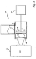
- Fig. 4 shows compression of the grinded sample and presentation of the grinded sample for the analysis system 19.
- the pressing means here the plunger 14 with the knives 12 in front of it, driven by the compression means, compresses the sample material against the analysis window 18 in order to achieve a good presentation of the sample for the analysis system.
- the compression of the sample is here made essentially perpendicularly against the analysis window so that the compression of the sample material becomes more homogeneous.
- the plunger 14 is preferably arranged such that air is allowed to leak over from the decreasing space for the sample to the other side during the compression, in order to maintain the same air pressure around the sample to be analysed.
- the degree of compression may be predetermined so that similar analysis conditions, in terms of compression of the sample material and amount of air between the pieces of sample material, are achieved for different sample analyses.
- the second motor may hereby be arranged to automatically stop pressing the plunger 14 against the sample at a predetermined counter force from the sample.
- the counter force from the sample may for example be measured by means of a pressure sensor (not shown) arranged on the plunger 14 or by means of a voltage or current gauge at the compression means which drives the plunger 14.
- Fig. 5 shows output of the sample from the grinding chamber 11 after the compression and presentation of the sample for the analysis system.
- the sample is output by opening of the second closing means, here the cover 16 with the analysis window 18, and movement of the plunger 14 forward to the second chamber opening so that the sample is pushed out from the grinding chamber 11.
- the output sample may be collected for further analysis or for recycling back to the process line.
- the analysis window 18 may be cleaned if it is contaminated with sample material.
- Fig. 6 shows an alternative embodiment of a device 20 according to the invention which is able to automatically clean the analysis window 28 after presentation of a sample for an analysis system 29.
- the device 20 comprises, just like the device 10 in Figs 1 to 5 , a rotor 23, driven by a motor 27, knives 22 arranged on the rotor 23 for grinding the sample inside a grinding chamber 21, and a plunger 24 for compression and output of the sample from the grinding chamber 21.
- the device also comprises a first chamber opening which may be covered by a first closing means, here a sliding lid 25, and a second chamber opening which may be covered by a second closing means, here a cover 26 comprising the analysis window 28.
- the difference compared to the device 10 is that the cover 26 is movable in the plane of the second chamber opening, so that remains from the sample may be wiped off the analysis window 28 automatically against the rim of the second chamber opening when the cover 26 is opened for output of the sample from the grinding chamber 21.
- Fig. 7 shows another embodiment of a device 30 according to the invention, where a NIT (Near Infrared Transmission) analysis system 39 may be used for analysis of a sample presented by the device 30.
- NIT Near Infrared Transmission
- the light that is transmitted through the sample material is analysed.
- This device 30 comprises, like the device shown in Figs 1 to 5 and the device shown in Fig. 6 , a grinding chamber 31, knives 32, a rotor 33, a plunger 34, a sliding lid 35, a cover 36, a motor 37, and an analysis window 38.
- the analysis window 38 is wedge-shaped in the direction out from the grinding chamber 31, so that NIT analysis may be performed perpendicularly to the direction of the compression of the sample. Because the analysis window 38 is wedge-shaped, the shape of the knives 32 is modified so that the whole grinding chamber 31 may be reached by the rotating knives 32.
- NIT analysis system 39 may simply be moved parallell to the direction of the axis of the rotor 33 in order to change the distance that the light travels through the sample material.
- the NIR and NIT analysis systems used together with the above described embodiments work with infrared light.
- the invention may be used for analysis within other parts of the electromagnetic frequency spectrum as well.
- the device according to the invention may also be used for sample preparation before other analyses than spectral analyses, like for example chemical analyses.
Landscapes
- Physics & Mathematics (AREA)
- Spectroscopy & Molecular Physics (AREA)
- Health & Medical Sciences (AREA)
- Life Sciences & Earth Sciences (AREA)
- Chemical & Material Sciences (AREA)
- Analytical Chemistry (AREA)
- Biochemistry (AREA)
- General Health & Medical Sciences (AREA)
- General Physics & Mathematics (AREA)
- Immunology (AREA)
- Pathology (AREA)
- Engineering & Computer Science (AREA)
- Food Science & Technology (AREA)
- Medicinal Chemistry (AREA)
- Sampling And Sample Adjustment (AREA)
- Investigating Or Analysing Materials By Optical Means (AREA)
- Disintegrating Or Milling (AREA)
- Analysing Materials By The Use Of Radiation (AREA)
Abstract
Description
- The present invention relates to a device and a method for grinding a sample and presenting the sample for an analysis system.
- A device according to above may be used to facilitate spectrometric analysis of a product sample, consisting of e.g. pasta, grain, other feedstuff, or industrial material components, which should be grinded before the analysis. Selection of the sample may be made directly from a process line (On-Line analysis sampling). Common types of spectrometric analyses which may be used are Near Infrared Reflection (NIR) and Near Infrared Transmission (NIT) analysis.
- In
EP 0365205 A2 there is described an apparatus for evaluating raw coffee beans. The apparatus comprises a sample supply mechanism including a hopper for receiving coffee beans. Below the hopper, a pulverizing chamber is arranged which includes grinding rollers for grinding and pulverizing the coffee beans inside the pulverizing chamber. Beside the pulverizing chamber, the apparatus comprises a separate measuring chamber including a near-infrared spectrometer. - The apparatus further comprises a sample container for receiving therein sample coffee powder to be evaluated which has been ground or pulverized in the pulverizing chamber. The sample container has a transparent bottom wall and is held by a holder. The holder is movable between a filling position below the pulverizing chamber and a measuring position at a predetermined measuring position in a lower portion in the measuring chamber. When the holder moves from the filling position to the measuring position, a roller rotated by a motor is brought into rolling contact with the top of the sample container held by the holder to compressively fill the sample coffee powder into the sample container and to remove excessive sample coffee powder from the sample container.
-
US 5,810,472 relates to an electric hand blender for continuous mixing of foodstuff in a container. Food material is aspirated into a lower chamber of the blender by a lower aperture of the blender casing, and the pureed material is expelled through slots provided in the circumference of the casing. A channel to the lower chamber from an upper chamber allows air to be fed into the lower chamber, preventing a vacuum from being formed by a spinning cutter blade in the lower chamber. -
US 4,072,275 relates to a sample preparation device comprising a mill above a centrifuge. A sample is fed through a filling opening of the mill after which it is crushed by a pestle against the bottom surface of the mill casing. After crushing, the sample is pushed by the pestle though a discharge pipe to enter the centrifuge. -
US 5,183,215 relates to a grinding appliance in which a material is pressed into a grinding chamber from a storage vessel by means of an air-pressure connection. In the grinding chamber, the material is ground by an agitator body, after which the ground material exits through an outlet. - An object of the present invention is to provide an improved device and method for grinding a sample and presenting the sample for an analysis system.
- Another object of the present invention is to provide a simplified and rationalized device and method for grinding a sample and presenting the sample for an analysis system.
- For achieving at least some of these and other objects, a device and a method as defined in the appended independent claims are provided. Preferred embodiments of the invention are defined in the dependent claims.
- According to one aspect, the present invention relates to a device for use in an analysis system, comprising a grinding chamber, a grinding means for grinding a sample in said grinding chamber; pressing means for compression of said sample in said grinding chamber a first chamber opening for input of said sample into said grinding chamber; and a second chamber opening separate from said first chamber opening for output of said sample from said grinding chamber; characterised in that the device further comprises a first closing means which is arranged for closing said second chamber opening and which comprises an analysis window, and said pressing means is arranged to compress said sample essentially perpendicularly against the analysis window for presentation for said analysis system while said sample is inside said grinding chamber.
- As defined herein, "grinding" means transformation of the material into smaller particles. Hence, grinding also includes atomization or pulverization of a solid material, as well as coarse grinding. The grinding may be accomplished by means of cutting, milling, or some other process.
- According to the invention, both grinding and compression of the sample are made while the sample is inside the grinding chamber. The compression is made in order to make the sample homogeneous for said use in the analysis system. The present invention makes it possible to perform spectrometric analysis while the sample is still inside the grinding chamber. Hence, the invention eliminates the need for moving the grinded sample from the grinding chamber to a separate measuring chamber for analysis, wherefore the analysis process can be rationalized.
- Said grinding chamber is arranged to allow presentation of said sample for said analysis system while said sample is inside said grinding chamber.
- According to one embodiment of the invention, said pressing means further is arranged to output said sample from said grinding chamber. Thus, two functions are achieved by one single means.
- In another embodiment of the invention, said device further comprises a chamber opening for output of said sample from said grinding chamber, wherein said chamber opening is arranged to be closed during said compression of said sample. By having the chamber opening for sample output closed during said compression, it is possible to achieve controllable compression of the sample for analysis. Controllable compression makes it possible to accomplish similar analysis conditions from one sample analysis to another. This improves the repeatability and comparability between different sample analyses.
- Especially when spectrum analysis, such as NIR or NIT analysis, is used, it is important to control the compression of the sample, since different compressions result in different spectra. The only interesting parameter for spectral analysis is the spectra of the sample material, wherefore the influence or variation of all other parameters, including compression of the sample, particle size (degree of grinding of the material), air pressure, heat, moisture etc, must be reduced as much as possible.
- In another embodiment, said chamber opening is arranged to be closed during presentation of said sample for said analysis system. Thus, said controllable compression can be maintained during the presentation.
- According to the invention, the device further comprises a first chamber opening for input of said sample into said grinding chamber, and a second chamber opening for output of said sample from said grinding chamber, wherein said first chamber opening is separate from said second chamber opening. By having one chamber opening for input of the sample and another chamber opening for output of the sample, repetitive sample analysis is facilitated because one sample can be fed out from the grinding chamber while another sample is fed into the grinding chamber.
- In yet another embodiment, said first chamber opening is arranged to be closed during said compression of said sample. Depending on the actual construction of the grinding chamber, a closed first chamber opening during the compression further facilitates controllable compression.
- In yet another embodiment of the invention, said pressing means is arranged to compress said sample to a predetermined compression for said presentation for the analysis system. This makes it possible to minimize the variations in compression between different samples. As explained above, variations in the compression affects the result of a spectral analysis.
- In another embodiment, said pressing means is arranged to automatically stop compressing said sample at a predetermined counter force from the sample. Automatic stop of the compression increases the efficiency and reliability of the process. The counter force from the sample could for example be measured by means of a pressure sensor of the pressing means or by means of a voltage or current gauge at a motor which drives the pressing means.
- In another embodiment, said compression of said sample by said pressing means is accomplished by means of a compressed-air device to which the pressing means is connected. The use of a compressed-air device is advantageous since with such a device, the same compression may be achieved, from one sample analysis to another, irrespective of the size of the sample. This is because the magnitude of the compression is determined by the air pressure of the compressed-air device.
- According to the invention, said pressing means is arranged to compress said sample essentially perpendicularly against an analysis window for said presentation for the analysis system. An advantage with this is that the compression may be made more homogeneous over the whole sample, in order to further improve the controllability of the compression.
- According to the invention, a second closing means which is arranged for closing said second chamber opening comprises said analysis window. Thereby both the compression of the sample towards the analysis window for the analysis and the output of the sample from the grinding chamber may be made in the same direction by means of the pressing means.
- According to another embodiment, said second closing means is movable away from said second chamber opening. This makes it possible to output the sample from the grinding chamber.
- In another embodiment of the invention, said pressing means is movable at least as far as to the plane of said second chamber opening. This makes it possible to output the whole sample from the device, without leaving any piece of the sample inside the device.
- In yet another embodiment, said second closing means is movable in the plane of said second chamber opening. In the case when the closing means comprises the analysis window, this embodiment makes it possible to arrange so that remains from the sample are wiped off the analysis window automatically when the closing means is opened for output of the sample from the grinding chamber.
- In an alternative embodiment of the invention, said second closing means is movable perpendicularly to the plane of said second chamber opening. This embodiment is suitable if manual cleaning of the analysis window is preferred.
- In another embodiment of the invention, said first chamber opening is arranged to be closed by means of a first closing means which is movable in the plane of said first chamber opening. This makes it possible to arrange the device with its first chamber opening directly adjacent to a process line, from which samples are taken into the grinding chamber through the first chamber opening.
- In yet another embodiment of the invention, said first chamber opening is arranged for input of said sample essentially perpendicularly in relation to the direction of said compression of said sample. This facilitates a simple construction of the device.
- In a further embodiment of the invention, said device is arranged to present said sample for a Near Infrared Reflection analysis system, which is a well established analysis method within e.g. the food industry.
- In another embodiment, said device is arranged to present said sample for a Near Infrared Transmission analysis system, which is another similar well established analysis method.
- According to another embodiment of the invention, said grinding means comprises a rotatable and axially movable rotor being movable back and forth along an axis in said grinding chamber. Such construction of the grinding means enables efficient grinding of the sample in the whole grinding chamber.
- According to another embodiment, said pressing means is movable back and forth along said axis in said grinding chamber. Thus, compression and output of said sample may be performed simply by moving the pressing means along said axis.
- Preferably, said grinding means is movable separately from said pressing means, so that no compression is made during grinding.
- According to yet another embodiment, at least a part of said grinding means is located on the same side in relation to said pressing means as said sample during said compression of the sample. This facilitates a simple design of the device.
- According to another aspect, the present invention relates to a method for grinding a sample and presenting the sample for an analysis system, said method comprising inputting said sample into a grinding chamber through a first chamber opening, grinding said sample in said grinding chamber when a second chamber opening, located separate from the first chamber opening, is closed by a closing means; compressing said grinded sample in said grinding chamber, presenting said grinded and compressed sample in said grinding chamber for said analysis system at a window in the closing means; and opening said closing means and outputting said sample from said grinding chamber through said second chamber opening.
- According to the invention, said input of said sample into said grinding chamber is made through a first chamber opening whereas said output of said sample from said grinding chamber is made through a second chamber opening, wherein said second chamber opening is separate from said first chamber opening.
- According to another embodiment of the invention, said second chamber opening is closed during said compression of said grinded sample.
- According to another embodiment, said compression of said grinded sample is made to a predetermined compression for said presentation for the analysis system.
- According to another embodiment, said compression of said grinded sample stops automatically at a predetermined counter force from the sample.
- According to the invention said compression of said grinded sample is made essentially perpendicularly against an analysis window for said presentation.
- In another embodiment of the invention, said presentation is made for a Near Infrared Reflection analysis system.
- In yet another embodiment of the invention, said presentation is made for a Near Infrared Transmission analysis system.
- The present invention will now be described in more detail with reference to the accompanying drawings, in which
-
Fig. 1 is a schematic view of one embodiment of a device according to the invention; -
Fig. 2 is a schematic view illustrating selection of a sample to the device shown inFig. 1 ; -
Fig. 3 is a schematic view illustrating grinding of a selected sample using the device shown inFig. 1 ; -
Fig. 4 is a schematic view illustrating compression and presentation of a sample for a NIR analysis system using the device shown inFig. 1 ; -
Fig. 5 is a schematic view illustrating output of a sample from the device shown inFig. 1 ; -
Fig. 6 is a schematic view of another embodiment of a device according to the invention; -
Fig. 7 is a schematic view of yet another embodiment of a device according to the invention. -
Fig. 1 shows one embodiment of adevice 10 according to the invention. Thedevice 10 comprises a grindingchamber 11, a grinding means, here in the form of a number ofknives 12 arranged on a rotatable and axiallymovable rotor 13, for grinding a sample of a material in the grindingchamber 11, and a pressing means, here in the form of aplunger 14 which encompasses therotor 13, for compression of the sample in and output of the sample from the grindingchamber 11. The axis of therotor 13 extends parallell to the longitudinal axis of the grindingchamber 11. - The
device 10 further comprises a first chamber opening for input of the sample into the grindingchamber 11, and a second chamber opening for output of the sample from the grindingchamber 11. A first closing means, here in the form of a slidinglid 15, is arranged for covering the first chamber opening, and a second closing means, here in the form of acover 16 which is movable perpendicularly to the plane of the second chamber opening, is arranged for covering the second chamber opening. - A
motor 17 is arranged to rotate therotor 13 with theknives 12, and a compression means (not shown), for example a compressed-air device, is arranged to press theplunger 14 against the sample for compression and output of the sample from the grindingchamber 11. A second motor (not shown), is also arranged for moving therotor 13 with theknives 12 and themotor 17 backwards and forwards in the grindingchamber 11. Alternatively, the functions of the compression means and the second motor may be provided by one single motor unit. - In the second closing means, an
analysis window 18 is arranged for presentation of the sample for an analysis system, here a NIR (Near Infrared Reflection)analysis system 19, which analyses the light that is reflected from the sample material back to theNIR analysis system 19. -
Figs 2 to 5 show the use of the device inFig. 1 for combined selection of a sample (Fig. 2 ), grinding of the selected sample (Fig. 3 ), and presentation of the sample for the analysis system 19 (Fig. 4 ), whereafter the sample is outputted from the grinding chamber 11 (Fig. 5 ). - In
Fig. 2 is illustrated how the sample, for example directly from a process line, is taken into the grindingchamber 11 by opening of the slidinglid 15. When the slidinglid 15 is moved parallell to the plane of the first chamber opening and uncovers this opening, the sample will fall into the grindingchamber 11 by means of the gravity. After the input of the sample to the grindingchamber 11, the first chamber opening is closed. - The material of the sample is streamable but not liquid. Examples of materials to which the
device 10 is applicable are pasta, grain and other feedstuff, or industrial material components such as pellets and other plastics. - The first closing means, here the sliding
lid 15, may be specially designed so that sample material not happen to get stuck between the first closing means and the rim of the first chamber opening. For example, the slidinglid 15 may be provided with a sharp edge which cuts pieces of material that have been jammed between the slidinglid 15 and the rim of the first chamber opening. -
Fig. 3 shows grinding of the sample, which inFig. 2 was taken into the grindingchamber 11. The sample is grinded by means of the grinding means, here the rotatingknives 12 on therotor 13, which is moved backwards and forwards in the grindingchamber 11 by means of the second motor. - The degree of grinding of the material is determined by the rotation speed of the
knives 12 and by the number of times that theknives 12 are moved backwards and forwards in the grindingchamber 11. -
Fig. 4 shows compression of the grinded sample and presentation of the grinded sample for theanalysis system 19. The pressing means, here theplunger 14 with theknives 12 in front of it, driven by the compression means, compresses the sample material against theanalysis window 18 in order to achieve a good presentation of the sample for the analysis system. The compression of the sample is here made essentially perpendicularly against the analysis window so that the compression of the sample material becomes more homogeneous. Theplunger 14 is preferably arranged such that air is allowed to leak over from the decreasing space for the sample to the other side during the compression, in order to maintain the same air pressure around the sample to be analysed. - The degree of compression may be predetermined so that similar analysis conditions, in terms of compression of the sample material and amount of air between the pieces of sample material, are achieved for different sample analyses. The second motor may hereby be arranged to automatically stop pressing the
plunger 14 against the sample at a predetermined counter force from the sample. The counter force from the sample may for example be measured by means of a pressure sensor (not shown) arranged on theplunger 14 or by means of a voltage or current gauge at the compression means which drives theplunger 14. - When the sample is compressed to the predetermined compression, spectral analysis with the
NIR analysis system 19 of the sample is performed through theanalysis window 18. -
Fig. 5 shows output of the sample from the grindingchamber 11 after the compression and presentation of the sample for the analysis system. The sample is output by opening of the second closing means, here thecover 16 with theanalysis window 18, and movement of theplunger 14 forward to the second chamber opening so that the sample is pushed out from the grindingchamber 11. - The output sample may be collected for further analysis or for recycling back to the process line.
- After the output of the sample from the grinding
chamber 11 and while the second chamber opening still is open, theanalysis window 18 may be cleaned if it is contaminated with sample material. -
Fig. 6 shows an alternative embodiment of adevice 20 according to the invention which is able to automatically clean theanalysis window 28 after presentation of a sample for ananalysis system 29. Thedevice 20 comprises, just like thedevice 10 inFigs 1 to 5 , arotor 23, driven by amotor 27,knives 22 arranged on therotor 23 for grinding the sample inside a grinding chamber 21, and aplunger 24 for compression and output of the sample from the grinding chamber 21. The device also comprises a first chamber opening which may be covered by a first closing means, here a slidinglid 25, and a second chamber opening which may be covered by a second closing means, here acover 26 comprising theanalysis window 28. - The difference compared to the
device 10 is that thecover 26 is movable in the plane of the second chamber opening, so that remains from the sample may be wiped off theanalysis window 28 automatically against the rim of the second chamber opening when thecover 26 is opened for output of the sample from the grinding chamber 21. -
Fig. 7 shows another embodiment of adevice 30 according to the invention, where a NIT (Near Infrared Transmission)analysis system 39 may be used for analysis of a sample presented by thedevice 30. When NIT analysis is used, the light that is transmitted through the sample material is analysed. - This
device 30 comprises, like the device shown inFigs 1 to 5 and the device shown inFig. 6 , a grindingchamber 31,knives 32, arotor 33, aplunger 34, a slidinglid 35, acover 36, amotor 37, and ananalysis window 38. The difference is that in this embodiment, theanalysis window 38 is wedge-shaped in the direction out from the grindingchamber 31, so that NIT analysis may be performed perpendicularly to the direction of the compression of the sample. Because theanalysis window 38 is wedge-shaped, the shape of theknives 32 is modified so that the whole grindingchamber 31 may be reached by the rotatingknives 32. - A special advantage with this construction is that the
NIT analysis system 39 may simply be moved parallell to the direction of the axis of therotor 33 in order to change the distance that the light travels through the sample material. - The NIR and NIT analysis systems used together with the above described embodiments work with infrared light. However, the invention may be used for analysis within other parts of the electromagnetic frequency spectrum as well.
- Further, the device according to the invention may also be used for sample preparation before other analyses than spectral analyses, like for example chemical analyses.
Claims (17)
- A device (10;20;30) for use in an analysis system (19;29;39), comprising a grinding chamber (11 ;21 ;31), a grinding means (12;22;32) for grinding a sample in said grinding chamber (11 ;21 ;31); pressing means (14;24;34) for compression of said sample in said grinding chamber (11 ;21 ;31) a first chamber opening for input of said sample into said grinding chamber (11;21;31); and a second chamber opening separate from said first chamber opening for output of said sample from said grinding chamber (11 ;21 ;31); characterised in that the device further comprises a first closing means (16;26;36) which is arranged for closing said second chamber opening and which comprises an analysis window (18;28;38), and said pressing means (14;24;34) is arranged to compress said sample essentially perpendicularly against the analysis window (18;28; 38) for presentation for said analysis system (19;29;39) while said sample is inside said grinding chamber (11 ;21 ;31).
- A device according to claim 1, wherein said pressing means (14;24;34) further is arranged to output said sample from said grinding chamber (11 ;21 ;31).
- A device (10;20;30) according to claim 1 or claim 2 characterized in that there is provided a second closing means operable to close said first chamber opening during said compression of said sample.
- A device (10;20;30) according to any one of the preceding claims, wherein said pressing means (14;24;34) is arranged to compress said sample to a predetermined compression for presentation for said analysis system (19;29;39).
- A device (10;20;30) according to any one of the preceding claims, wherein said pressing means (14;24;34) is arranged to automatically stop compressing said sample at a predetermined counter force from the sample.
- A device (10;20;30) according to any one of the preceding claims, characterized in that there is further provided a compressed air device operably attached to said pressing means (14;24;34) to effect said compression of said sample by said pressing means (14;24; 34).
- A device (10;20;30) according to claim 1, wherein said first closing means (16;26;36) is movable away from said second chamber opening.
- A device (10;20;30) according to claim 7, wherein said pressing means (14;24;34) is movable at least as far as to the plane of said second chamber opening.
- A device (20) according to claim 1, wherein said first closing means (16;26;36) is movable in the plane of said second chamber opening.
- A device (10;30) according claim 1, wherein said first closing means (16;26;36) is movable perpendicularly to the plane of said second chamber opening.
- A device (10;20) according to any one of the preceding claims, wherein said device (10;20) is arranged to present said sample for a Near Infrared Reflection analysis system (19;29).
- A device (10;20;30) according to any one of the preceding claims, wherein said device (10;20;30) is arranged to present said sample for a Near Infrared Transmission analysis system (39).
- A device (10;20;30) according to any one of the preceding claims, wherein said grinding means (12;22;32) comprises a rotatable and axially movable rotor (13;23;33) being movable back and forth along an axis in said grinding chamber (11;21;31).
- A device (10;20;30) according to claim13, wherein said pressing means (14;24;34) is movable back and forth along said axis in said grinding chamber (11;21;31).
- A device (10;20;30) according to any one of the preceding claims, wherein said grinding means (12;22;32) is movable separately from said pressing means (14;24;34).
- A method for grinding a sample and presenting the sample for an analysis system (19;29; 39), said method comprising inputting said sample into a grinding chamber (11 ;21 ;31) through a first chamber opening, grinding said sample in said grinding chamber (11;21; 31) when a second chamber opening, located separate from the first chamber opening, is closed by a closing means; compressing said grinded sample in said grinding chamber (11;21;31), presenting said grinded and compressed sample in said grinding chamber (11;21;31) for said analysis system (19;29;39) at a window in the closing means; and opening said closing means and outputting said sample from said grinding chamber (11 ;21 ;31) through said second chamber opening.
- A method according to claim 16, wherein said compression of said grinded sample is made essentially perpendicularly against an analysis window (18;28;38) for said act of presenting the sample.
Applications Claiming Priority (3)
| Application Number | Priority Date | Filing Date | Title |
|---|---|---|---|
| SE0202011A SE523973C2 (en) | 2002-06-28 | 2002-06-28 | Arrangement and method of sampling, grinding and sample presentation for analysis |
| SE0202011 | 2002-06-28 | ||
| PCT/SE2003/001120 WO2004003525A1 (en) | 2002-06-28 | 2003-06-27 | Grinding and sample presentation for analysis |
Publications (2)
| Publication Number | Publication Date |
|---|---|
| EP1518106A1 EP1518106A1 (en) | 2005-03-30 |
| EP1518106B1 true EP1518106B1 (en) | 2009-08-19 |
Family
ID=20288362
Family Applications (1)
| Application Number | Title | Priority Date | Filing Date |
|---|---|---|---|
| EP03733810A Expired - Lifetime EP1518106B1 (en) | 2002-06-28 | 2003-06-27 | Grinding and sample presentation for analysis |
Country Status (7)
| Country | Link |
|---|---|
| US (1) | US6739207B2 (en) |
| EP (1) | EP1518106B1 (en) |
| AT (1) | ATE440272T1 (en) |
| AU (1) | AU2003239095A1 (en) |
| DE (1) | DE60328893D1 (en) |
| SE (1) | SE523973C2 (en) |
| WO (1) | WO2004003525A1 (en) |
Families Citing this family (11)
| Publication number | Priority date | Publication date | Assignee | Title |
|---|---|---|---|---|
| CA2456608C (en) * | 2003-01-31 | 2009-01-06 | Universidad Tecnica Federico Santa Maria | A system to determine and analyze the dynamic internal load in revolving mills, for mineral grinding |
| TW200905672A (en) * | 2007-07-30 | 2009-02-01 | Mediatek Inc | Method of data accessing and optical data accessing apparatus therefor |
| WO2013172920A1 (en) * | 2012-05-16 | 2013-11-21 | Poet Research, Inc. | Systems and methods for automated biomass sampling and analysis |
| GB2548652A (en) * | 2014-04-18 | 2017-09-27 | Horiba Ltd | Sample dispersion device and sample dispersion method |
| CN109794426A (en) * | 2017-11-16 | 2019-05-24 | 钢铁研究总院 | Fully automatic online aviation aluminum sorting and recycling system based on LIBS technology |
| CN108132173A (en) * | 2017-11-30 | 2018-06-08 | 安徽宏远职业卫生技术服务有限公司 | The sample pretreating method of acesulfame potassium in a kind of detection faces based food |
| DK180133B1 (en) * | 2018-11-07 | 2020-06-09 | Atline Aps | Device for automated and contamination-free sampling and analysis |
| US20210080358A1 (en) * | 2019-08-28 | 2021-03-18 | Elite IP, LLC | Systems and methods for collecting, processing, optimizing, and preparing stem cells for further use |
| CN112595568B (en) * | 2020-12-11 | 2022-09-27 | 通标标准技术服务(天津)有限公司 | Coal mine quality detection device |
| CN113341067B (en) * | 2021-05-25 | 2023-02-21 | 贵州省产品质量检验检测院 | Movable combined device for rapidly determining specific components in chemical fertilizer |
| DK181885B1 (en) * | 2022-06-22 | 2025-03-06 | Atline Aps | Production system with near-infrared spectrometer |
Citations (3)
| Publication number | Priority date | Publication date | Assignee | Title |
|---|---|---|---|---|
| US4072275A (en) * | 1975-12-05 | 1978-02-07 | Mettler Instruments Ag | Sample preparation device |
| US5183215A (en) * | 1987-12-03 | 1993-02-02 | Hermann Getzmann | Grinding appliance |
| US5810472A (en) * | 1995-02-13 | 1998-09-22 | Braun Aktiengesellschaft | Hand blender for mixing or comminuting foodstuffs with an air supply structure |
Family Cites Families (12)
| Publication number | Priority date | Publication date | Assignee | Title |
|---|---|---|---|---|
| US4400086A (en) | 1979-06-04 | 1983-08-23 | Pacific Scientific Instruments Company | Instrument for grinding and analyzing material in ground state |
| DE3448134C2 (en) | 1984-04-19 | 1989-05-03 | Gebrueder Buehler Ag, Uzwil, Ch | |
| MX169020B (en) | 1986-09-19 | 1993-06-16 | Satake Eng Co Ltd | MEASURING DEVICE FOR AMYLOSE AND / OR AMYLOPECTIN CONTENT IN RICE |
| CH674474A5 (en) * | 1987-12-07 | 1990-06-15 | Max Gutknecht | |
| DK172088D0 (en) * | 1988-03-29 | 1988-03-29 | Jesma Matador As | PROCEDURE FOR CARRYING OUT ANALYSIS OF SUCCESSIVE MATERIAL TESTS BY THE NIR METHOD AND PLACES TO EXERCISE THE PROCEDURE |
| IE65900B1 (en) | 1988-10-15 | 1995-11-29 | Satake Eng Co Ltd | Apparatus for evaluating quality of raw coffee beans |
| FI901257L (en) * | 1990-03-14 | 1991-09-15 | Outokumpu Oy | MAETCELL. |
| US5058444A (en) * | 1990-04-25 | 1991-10-22 | The United States Of America As Represented By The Secretary Of Agriculture | System for analyzing entrained solids such as cotton or seed |
| DK64492D0 (en) * | 1992-05-14 | 1992-05-14 | Jesma Matador As | PROCEDURES AND SPECIFICATIONS FOR HANDLING OF SAMPLING MATERIALS, e.g. IN MIX STATIONS FOR CENTRAL ANALYSIS OF SAMPLES |
| DK171926B1 (en) * | 1995-02-10 | 1997-08-11 | Slagteriernes Forskningsinst | Apparatus for examining flowable material and device for feeding samples |
| JPH09138205A (en) * | 1995-11-15 | 1997-05-27 | Agency Of Ind Science & Technol | Detection method for flaw of material by infrared thermography |
| US5700961A (en) * | 1996-06-19 | 1997-12-23 | The United States Of America As Represented By The Secretary Of Agriculture | System and method for measuring stickiness of materials such as cotton |
-
2002
- 2002-06-28 SE SE0202011A patent/SE523973C2/en not_active IP Right Cessation
- 2002-10-30 US US10/283,122 patent/US6739207B2/en not_active Expired - Fee Related
-
2003
- 2003-06-27 AT AT03733810T patent/ATE440272T1/en not_active IP Right Cessation
- 2003-06-27 EP EP03733810A patent/EP1518106B1/en not_active Expired - Lifetime
- 2003-06-27 AU AU2003239095A patent/AU2003239095A1/en not_active Abandoned
- 2003-06-27 WO PCT/SE2003/001120 patent/WO2004003525A1/en not_active Ceased
- 2003-06-27 DE DE60328893T patent/DE60328893D1/en not_active Expired - Lifetime
Patent Citations (3)
| Publication number | Priority date | Publication date | Assignee | Title |
|---|---|---|---|---|
| US4072275A (en) * | 1975-12-05 | 1978-02-07 | Mettler Instruments Ag | Sample preparation device |
| US5183215A (en) * | 1987-12-03 | 1993-02-02 | Hermann Getzmann | Grinding appliance |
| US5810472A (en) * | 1995-02-13 | 1998-09-22 | Braun Aktiengesellschaft | Hand blender for mixing or comminuting foodstuffs with an air supply structure |
Also Published As
| Publication number | Publication date |
|---|---|
| SE0202011D0 (en) | 2002-06-28 |
| ATE440272T1 (en) | 2009-09-15 |
| SE523973C2 (en) | 2004-06-08 |
| WO2004003525A1 (en) | 2004-01-08 |
| SE0202011L (en) | 2003-12-29 |
| US6739207B2 (en) | 2004-05-25 |
| AU2003239095A1 (en) | 2004-01-19 |
| US20040000202A1 (en) | 2004-01-01 |
| EP1518106A1 (en) | 2005-03-30 |
| DE60328893D1 (en) | 2009-10-01 |
Similar Documents
| Publication | Publication Date | Title |
|---|---|---|
| EP1518106A1 (en) | Grinding and sample presentation for analysis | |
| CN102665494B (en) | Electric kitchen appliance comprising a pressing screw and a pre-cutting device | |
| US5918977A (en) | Method and plant for mixing and analyzing unhomogeneous flowable foodstuff, fodder or pharmaceutical material | |
| US5605841A (en) | System for automatic sample analysis and a method for producing the system including a cleaning unit for a movable optical head | |
| KR101586467B1 (en) | Device for pulverization and extraction of agricultural product | |
| KR101586464B1 (en) | Device for pulverization and extraction of agricultural product | |
| CA1331766C (en) | Method and a system for handling sample materials, e.g. in mixing plants, for central analysis of the samples | |
| CA2568313A1 (en) | Grinding mill with air recirculation | |
| CN221377344U (en) | Crushing sampler for sample preparation | |
| CN118892882A (en) | Food testing sample crushing device | |
| CN218212907U (en) | Food heavy metal detection equipment | |
| AU752019B2 (en) | Automated sample analysis system | |
| CN111632706B (en) | High efficiency tobacco reducing mechanism | |
| US20070001039A1 (en) | Comminution mill | |
| KR200166568Y1 (en) | Pulverizing device for a multipose pulverizer | |
| KR20260043236A (en) | Apparatus for manufacturing pet food | |
| CN216543446U (en) | Dicing machine | |
| CN219356452U (en) | Sample smashing and sampling device for pesticide residue detection | |
| RU242326U1 (en) | Household machine for sorting and pre-processing household waste | |
| CN222267404U (en) | Powder receiving structure of pulverizer | |
| KR20030080461A (en) | the crusher and refine apparatus for powder | |
| GB2522649A (en) | Bag emptying system | |
| CN206746781U (en) | Ultramicro grinding conveying device is used in a kind of veterinary drug processing | |
| CZ283699B6 (en) | General-purpose kitchen machine | |
| CN119972315A (en) | Food crushing and grinding device |
Legal Events
| Date | Code | Title | Description |
|---|---|---|---|
| PUAI | Public reference made under article 153(3) epc to a published international application that has entered the european phase |
Free format text: ORIGINAL CODE: 0009012 |
|
| AK | Designated contracting states |
Kind code of ref document: A1 Designated state(s): AT BE BG CH CY CZ DE DK EE ES FI FR GB GR HU IE IT LI LU MC NL PT RO SE SI SK TR |
|
| AX | Request for extension of the european patent |
Extension state: AL LT LV MK |
|
| 17P | Request for examination filed |
Effective date: 20041215 |
|
| DAX | Request for extension of the european patent (deleted) | ||
| 17Q | First examination report despatched |
Effective date: 20081205 |
|
| GRAP | Despatch of communication of intention to grant a patent |
Free format text: ORIGINAL CODE: EPIDOSNIGR1 |
|
| RIC1 | Information provided on ipc code assigned before grant |
Ipc: G01N 1/28 20060101AFI20090325BHEP Ipc: G01N 21/35 20060101ALI20090325BHEP |
|
| GRAS | Grant fee paid |
Free format text: ORIGINAL CODE: EPIDOSNIGR3 |
|
| GRAA | (expected) grant |
Free format text: ORIGINAL CODE: 0009210 |
|
| AK | Designated contracting states |
Kind code of ref document: B1 Designated state(s): AT BE BG CH CY CZ DE DK EE ES FI FR GB GR HU IE IT LI LU MC NL PT RO SE SI SK TR |
|
| REG | Reference to a national code |
Ref country code: GB Ref legal event code: FG4D |
|
| REG | Reference to a national code |
Ref country code: CH Ref legal event code: EP |
|
| REG | Reference to a national code |
Ref country code: IE Ref legal event code: FG4D |
|
| REF | Corresponds to: |
Ref document number: 60328893 Country of ref document: DE Date of ref document: 20091001 Kind code of ref document: P |
|
| PG25 | Lapsed in a contracting state [announced via postgrant information from national office to epo] |
Ref country code: ES Free format text: LAPSE BECAUSE OF FAILURE TO SUBMIT A TRANSLATION OF THE DESCRIPTION OR TO PAY THE FEE WITHIN THE PRESCRIBED TIME-LIMIT Effective date: 20091130 Ref country code: AT Free format text: LAPSE BECAUSE OF FAILURE TO SUBMIT A TRANSLATION OF THE DESCRIPTION OR TO PAY THE FEE WITHIN THE PRESCRIBED TIME-LIMIT Effective date: 20090819 Ref country code: FI Free format text: LAPSE BECAUSE OF FAILURE TO SUBMIT A TRANSLATION OF THE DESCRIPTION OR TO PAY THE FEE WITHIN THE PRESCRIBED TIME-LIMIT Effective date: 20090819 Ref country code: SE Free format text: LAPSE BECAUSE OF FAILURE TO SUBMIT A TRANSLATION OF THE DESCRIPTION OR TO PAY THE FEE WITHIN THE PRESCRIBED TIME-LIMIT Effective date: 20090819 |
|
| NLV1 | Nl: lapsed or annulled due to failure to fulfill the requirements of art. 29p and 29m of the patents act | ||
| PG25 | Lapsed in a contracting state [announced via postgrant information from national office to epo] |
Ref country code: SI Free format text: LAPSE BECAUSE OF FAILURE TO SUBMIT A TRANSLATION OF THE DESCRIPTION OR TO PAY THE FEE WITHIN THE PRESCRIBED TIME-LIMIT Effective date: 20090819 Ref country code: NL Free format text: LAPSE BECAUSE OF FAILURE TO SUBMIT A TRANSLATION OF THE DESCRIPTION OR TO PAY THE FEE WITHIN THE PRESCRIBED TIME-LIMIT Effective date: 20090819 |
|
| PG25 | Lapsed in a contracting state [announced via postgrant information from national office to epo] |
Ref country code: PT Free format text: LAPSE BECAUSE OF FAILURE TO SUBMIT A TRANSLATION OF THE DESCRIPTION OR TO PAY THE FEE WITHIN THE PRESCRIBED TIME-LIMIT Effective date: 20091221 Ref country code: BG Free format text: LAPSE BECAUSE OF FAILURE TO SUBMIT A TRANSLATION OF THE DESCRIPTION OR TO PAY THE FEE WITHIN THE PRESCRIBED TIME-LIMIT Effective date: 20091119 Ref country code: CY Free format text: LAPSE BECAUSE OF FAILURE TO SUBMIT A TRANSLATION OF THE DESCRIPTION OR TO PAY THE FEE WITHIN THE PRESCRIBED TIME-LIMIT Effective date: 20090819 |
|
| PG25 | Lapsed in a contracting state [announced via postgrant information from national office to epo] |
Ref country code: RO Free format text: LAPSE BECAUSE OF FAILURE TO SUBMIT A TRANSLATION OF THE DESCRIPTION OR TO PAY THE FEE WITHIN THE PRESCRIBED TIME-LIMIT Effective date: 20090819 Ref country code: CZ Free format text: LAPSE BECAUSE OF FAILURE TO SUBMIT A TRANSLATION OF THE DESCRIPTION OR TO PAY THE FEE WITHIN THE PRESCRIBED TIME-LIMIT Effective date: 20090819 Ref country code: DK Free format text: LAPSE BECAUSE OF FAILURE TO SUBMIT A TRANSLATION OF THE DESCRIPTION OR TO PAY THE FEE WITHIN THE PRESCRIBED TIME-LIMIT Effective date: 20090819 Ref country code: EE Free format text: LAPSE BECAUSE OF FAILURE TO SUBMIT A TRANSLATION OF THE DESCRIPTION OR TO PAY THE FEE WITHIN THE PRESCRIBED TIME-LIMIT Effective date: 20090819 |
|
| PG25 | Lapsed in a contracting state [announced via postgrant information from national office to epo] |
Ref country code: SK Free format text: LAPSE BECAUSE OF FAILURE TO SUBMIT A TRANSLATION OF THE DESCRIPTION OR TO PAY THE FEE WITHIN THE PRESCRIBED TIME-LIMIT Effective date: 20090819 |
|
| PLBE | No opposition filed within time limit |
Free format text: ORIGINAL CODE: 0009261 |
|
| STAA | Information on the status of an ep patent application or granted ep patent |
Free format text: STATUS: NO OPPOSITION FILED WITHIN TIME LIMIT |
|
| PG25 | Lapsed in a contracting state [announced via postgrant information from national office to epo] |
Ref country code: BE Free format text: LAPSE BECAUSE OF FAILURE TO SUBMIT A TRANSLATION OF THE DESCRIPTION OR TO PAY THE FEE WITHIN THE PRESCRIBED TIME-LIMIT Effective date: 20090819 |
|
| 26N | No opposition filed |
Effective date: 20100520 |
|
| PGFP | Annual fee paid to national office [announced via postgrant information from national office to epo] |
Ref country code: FR Payment date: 20100630 Year of fee payment: 8 |
|
| PG25 | Lapsed in a contracting state [announced via postgrant information from national office to epo] |
Ref country code: GR Free format text: LAPSE BECAUSE OF FAILURE TO SUBMIT A TRANSLATION OF THE DESCRIPTION OR TO PAY THE FEE WITHIN THE PRESCRIBED TIME-LIMIT Effective date: 20091120 |
|
| PGFP | Annual fee paid to national office [announced via postgrant information from national office to epo] |
Ref country code: DE Payment date: 20100629 Year of fee payment: 8 Ref country code: GB Payment date: 20100625 Year of fee payment: 8 |
|
| PG25 | Lapsed in a contracting state [announced via postgrant information from national office to epo] |
Ref country code: MC Free format text: LAPSE BECAUSE OF NON-PAYMENT OF DUE FEES Effective date: 20100630 |
|
| REG | Reference to a national code |
Ref country code: CH Ref legal event code: PL |
|
| PG25 | Lapsed in a contracting state [announced via postgrant information from national office to epo] |
Ref country code: IT Free format text: LAPSE BECAUSE OF FAILURE TO SUBMIT A TRANSLATION OF THE DESCRIPTION OR TO PAY THE FEE WITHIN THE PRESCRIBED TIME-LIMIT Effective date: 20090819 |
|
| PG25 | Lapsed in a contracting state [announced via postgrant information from national office to epo] |
Ref country code: IE Free format text: LAPSE BECAUSE OF NON-PAYMENT OF DUE FEES Effective date: 20100627 Ref country code: LI Free format text: LAPSE BECAUSE OF NON-PAYMENT OF DUE FEES Effective date: 20100630 Ref country code: CH Free format text: LAPSE BECAUSE OF NON-PAYMENT OF DUE FEES Effective date: 20100630 |
|
| GBPC | Gb: european patent ceased through non-payment of renewal fee |
Effective date: 20110627 |
|
| REG | Reference to a national code |
Ref country code: FR Ref legal event code: ST Effective date: 20120229 |
|
| REG | Reference to a national code |
Ref country code: DE Ref legal event code: R119 Ref document number: 60328893 Country of ref document: DE Effective date: 20120103 |
|
| PG25 | Lapsed in a contracting state [announced via postgrant information from national office to epo] |
Ref country code: FR Free format text: LAPSE BECAUSE OF NON-PAYMENT OF DUE FEES Effective date: 20110630 Ref country code: DE Free format text: LAPSE BECAUSE OF NON-PAYMENT OF DUE FEES Effective date: 20120103 |
|
| PG25 | Lapsed in a contracting state [announced via postgrant information from national office to epo] |
Ref country code: GB Free format text: LAPSE BECAUSE OF NON-PAYMENT OF DUE FEES Effective date: 20110627 |
|
| PG25 | Lapsed in a contracting state [announced via postgrant information from national office to epo] |
Ref country code: LU Free format text: LAPSE BECAUSE OF NON-PAYMENT OF DUE FEES Effective date: 20100627 Ref country code: HU Free format text: LAPSE BECAUSE OF FAILURE TO SUBMIT A TRANSLATION OF THE DESCRIPTION OR TO PAY THE FEE WITHIN THE PRESCRIBED TIME-LIMIT Effective date: 20100220 |
|
| PG25 | Lapsed in a contracting state [announced via postgrant information from national office to epo] |
Ref country code: TR Free format text: LAPSE BECAUSE OF FAILURE TO SUBMIT A TRANSLATION OF THE DESCRIPTION OR TO PAY THE FEE WITHIN THE PRESCRIBED TIME-LIMIT Effective date: 20090819 |