EP1517643B1 - Soft tissue repair tool - Google Patents
Soft tissue repair tool Download PDFInfo
- Publication number
- EP1517643B1 EP1517643B1 EP03739167A EP03739167A EP1517643B1 EP 1517643 B1 EP1517643 B1 EP 1517643B1 EP 03739167 A EP03739167 A EP 03739167A EP 03739167 A EP03739167 A EP 03739167A EP 1517643 B1 EP1517643 B1 EP 1517643B1
- Authority
- EP
- European Patent Office
- Prior art keywords
- guide wire
- bone
- friction fit
- tool
- pusher
- Prior art date
- Legal status (The legal status is an assumption and is not a legal conclusion. Google has not performed a legal analysis and makes no representation as to the accuracy of the status listed.)
- Expired - Lifetime
Links
- 210000004872 soft tissue Anatomy 0.000 title claims description 16
- 230000017423 tissue regeneration Effects 0.000 title description 3
- 210000000988 bone and bone Anatomy 0.000 claims abstract description 42
- 230000000149 penetrating effect Effects 0.000 claims description 4
- 238000005553 drilling Methods 0.000 abstract description 7
- 239000007943 implant Substances 0.000 description 20
- 238000000034 method Methods 0.000 description 10
- 210000001519 tissue Anatomy 0.000 description 9
- 230000000717 retained effect Effects 0.000 description 3
- 229920000642 polymer Polymers 0.000 description 2
- 238000002360 preparation method Methods 0.000 description 2
- 230000009471 action Effects 0.000 description 1
- 238000004026 adhesive bonding Methods 0.000 description 1
- 239000006260 foam Substances 0.000 description 1
- 238000002513 implantation Methods 0.000 description 1
- 238000003780 insertion Methods 0.000 description 1
- 230000037431 insertion Effects 0.000 description 1
- 230000003993 interaction Effects 0.000 description 1
- 238000003754 machining Methods 0.000 description 1
- 230000013011 mating Effects 0.000 description 1
- 239000002184 metal Substances 0.000 description 1
- 238000012986 modification Methods 0.000 description 1
- 230000004048 modification Effects 0.000 description 1
- 238000000465 moulding Methods 0.000 description 1
- 238000003825 pressing Methods 0.000 description 1
- 230000008569 process Effects 0.000 description 1
- 230000008439 repair process Effects 0.000 description 1
- 238000001356 surgical procedure Methods 0.000 description 1
- 238000003466 welding Methods 0.000 description 1
Images
Classifications
-
- A—HUMAN NECESSITIES
- A61—MEDICAL OR VETERINARY SCIENCE; HYGIENE
- A61B—DIAGNOSIS; SURGERY; IDENTIFICATION
- A61B17/00—Surgical instruments, devices or methods
- A61B17/16—Instruments for performing osteoclasis; Drills or chisels for bones; Trepans
- A61B17/17—Guides or aligning means for drills, mills, pins or wires
- A61B17/1714—Guides or aligning means for drills, mills, pins or wires for applying tendons or ligaments
-
- A—HUMAN NECESSITIES
- A61—MEDICAL OR VETERINARY SCIENCE; HYGIENE
- A61B—DIAGNOSIS; SURGERY; IDENTIFICATION
- A61B17/00—Surgical instruments, devices or methods
- A61B17/16—Instruments for performing osteoclasis; Drills or chisels for bones; Trepans
- A61B17/1697—Instruments for performing osteoclasis; Drills or chisels for bones; Trepans specially adapted for wire insertion
-
- A—HUMAN NECESSITIES
- A61—MEDICAL OR VETERINARY SCIENCE; HYGIENE
- A61B—DIAGNOSIS; SURGERY; IDENTIFICATION
- A61B17/00—Surgical instruments, devices or methods
- A61B17/16—Instruments for performing osteoclasis; Drills or chisels for bones; Trepans
- A61B17/1637—Hollow drills or saws producing a curved cut, e.g. cylindrical
-
- Y—GENERAL TAGGING OF NEW TECHNOLOGICAL DEVELOPMENTS; GENERAL TAGGING OF CROSS-SECTIONAL TECHNOLOGIES SPANNING OVER SEVERAL SECTIONS OF THE IPC; TECHNICAL SUBJECTS COVERED BY FORMER USPC CROSS-REFERENCE ART COLLECTIONS [XRACs] AND DIGESTS
- Y10—TECHNICAL SUBJECTS COVERED BY FORMER USPC
- Y10S—TECHNICAL SUBJECTS COVERED BY FORMER USPC CROSS-REFERENCE ART COLLECTIONS [XRACs] AND DIGESTS
- Y10S606/00—Surgery
- Y10S606/916—Tool for installing or removing orthopedic fastener
Definitions
- This invention relates to a soft tissue repair tool, and more particularly to a tool for preparing soft tissue and bone for implantation of a tissue fastener.
- United States Patent No 5,374,270 discloses a method and device for insertion of a guide pin into bone.
- the device is provided with a cannulated drill bit and a guide pin, retained releasably within the cannula by means of an adjustable force, for example by mating threads provided on the drill bit and guide pin.
- an adjustable force for example by mating threads provided on the drill bit and guide pin.
- the drill bit is removed while leaving the guide pin in place in the bone, so that the guide pin may assist in location of an implant.
- Embodiments of this aspect of the invention may include one or more of the following features.
- the member includes a guide wire retainer that receives the guide wire in the friction fit.
- the member includes a handle and a shaft coupled to the handle.
- the guide wire has a sharp distal end for penetrating soft tissue and bone.
- the member has a drill tip for forming a hole in bone.
- the member defines an internal shoulder which the guide wire pusher contacts to limit relative movement between the member and the guide wire pusher.
- the member is configured to provide the friction fit such that the guide wire is pre-assembled and secure within the member when the member is being introduced to a surgical site, and the friction fit is overcome when the guide wire is inserted into bone and the member is retracted relative to the guide wire.
- the surgical tool of the present invention enables a method for advancing a surgical tool to a surgical site, the surgical tool including a member, a guide wire received in the member, and a guide wire pusher, and applying a force to the guide wire pusher to advance the guide wire into bone moving the guide wire relative to the member to overcome a friction fit securing the guide wire to the member.
- Said method may include one or more of the following features.
- the method includes advancing the member relative to the guide wire to form a hole in the bone for receiving an implant.
- the advancement of the member relative to the guide wire is limited by interaction of the guide wire pusher with the member.
- the method includes withdrawing the member from the surgical site while maintaining the guide wire at the surgical site by overcoming the friction fit, and advancing an implant over the guide wire and into the bone hole.
- the guide wire retainer provides the friction fit and allows the guide wire to be held in such a way that it is pre-assembled and secure while the tool is being introduced to a surgical site. At the same time, once a hole is drilled into bone, the guide wire retainer allows the remainder of the tool to be removed leaving the guide wire in place at the site.
- the guide wire pusher allows the guide wire to be impacted into the bone before drilling and limits any possibility of drilling past the end of the guide wire.
- a soft tissue repair tool for bone preparation and implant deployment is easy to use, is presented pre-assembled in a single-case, pre-sterilized format, does not require separate assembly and dis-assembly steps, controls the relative position between the guide wire and shaft both before, during, and after drilling, requires only two instrument components, a drill tool and an inserter, to deploy an implant, and can be used arthroscopically or in an open or mini-open procedure.
- a drill tool 1 for preparing tissue to receive an implant includes an elongate member 1a having a shaft 2 and a handle 3 attached to a proximal region 8 of shaft 2, e.g., by pressing, gluing or welding.
- Shaft 2 defines a lumen 30, and handle 3 defines a lumen 32.
- Lumens 30, 32 are aligned and create a through passage 34 from a proximal end 36 of handle 3 to a distal end 7 of shaft 2.
- Tool 1 includes a guide wire 4 received within lumen 30 of shaft 2 and axially translatable relative to shaft 2, a guide wire pusher 5 received within lumen 32 of handle 3 and axially translatable relative to handle 3, and a guide wire retainer 6 received within proximal region 8 of shaft 2 that frictionally engages guide wire 4, for purposes described below.
- Guide wire 4 has a distal, sharp point 17 for penetrating soft tissue and bone, and shaft distal end 7 is formed to a sharp drilling tip 7a for forming a hole in bone.
- Handle 3 has a proximal hex feature 12 that allows releasable attachment of tool 1 to a power drilling tool (not shown).
- handle 3 has a first internal shoulder 10 extending into lumen 32, against which shaft 2 and guide wire retainer 6 are held, and a second internal shoulder 11 extending into lumen 32, which limits the proximal translation of the guide wire pusher 5 (arrow, A) by engagement of an enlarged, distal end 13 of guide wire pusher 5 with shoulder 11.
- Guide wire pusher distal end 13 defines an axially oriented blind hole 15 opening distally for removably receiving a proximal end 18 of guide wire 4.
- guide wire pusher 5 is used to distally advance guide wire 4 relative to shaft 2.
- proximal region 8 of shaft 2 is an outer cylindrical member 38 having an enlarged inner diameter region 38a for receiving guide wire retainer 6.
- Shaft 2 has a proximal end 8a that abuts against guide wire retainer 6.
- Guide wire retainer 6 defines a channel 19 through which guide wire 4 passes. There is a frictional fit between guide wire 4 and guide wire retainer 6 such that guide wire 4 is retained within tool 1 until guide wire 4 is fixed in the bone and tool 1 is removed from the bone, as described below.
- tool 1 is preferably packaged sterile with an implant inserter 20 and extra guide wires 21 in a foam carrier 22 (in case the guide wire 4 supplied in tool 1 is damaged during a procedure before all implants for that procedure are implanted) in a disposable tray 23.
- the components of tool 1 are preferably manufactured by polymer molding processes and machining and pressed assembled, though other methods using biocompatible metal(s) and polymer(s) can be used.
- Fig. 6A in use, with guide wire 4 positioned relative to shaft 2 as shown in Fig. 1 , i.e., with guide wire pusher 5 against internal shoulder 11, the operator passes distal point 17 of guide wire 4 and distal end 7 of shaft 2 through soft tissue 60 and against bone 62 at the reattachment site 64 on the bone.
- the operator impacts guide wire pusher 5 (arrow, B) with, e.g., a hammer, overcoming the friction fit between guide wire 4 and guide wire retainer 6 to advance guide wire 4 relative to shaft 2, until a proximal end 14 of guide wire pusher 5 is flush with a proximal end 40 of handle hex feature 12. This action lodges the distal end of guide wire 4 in bone 62 a distance equal to the length, I , of guide wire pusher 5 that extends from proximal end 40 when guide wire pusher 5 is against internal shoulder 11.
- the operator advances (arrow, C) and rotates (arrow, D) handle 3 and shaft 2, either by hand or with a power drill coupled to hex feature 12, to form a hole 66 in bone 62 greater than or equal to the length of the portion of the implant to be deployed within the bone.
- This can be aided by length markings (not shown) on shaft 2.
- the advancement of shaft 2 moves shaft 2 relative to guide wire 4 such that guide wire pusher 5 again protrudes from proximal end 40 of handle 3, and guide wire 4 is retained within shaft 2 by the friction fit with retainer 6.
- the operator then gives guide wire pusher 5 a few taps to dislodge any debris which may have become lodged in lumen 30 of shaft 2.
- the operator then removes shaft 2, handle 3, pusher 5, and retainer 6 from the patient.
- the friction fit is selected such that the force to overcome the lodgement of guide wire 4 within the bone is greater than the force to overcome the friction fit, such that guide wire 4 remains in place in the bone when the remainder of tool 1 is removed.
- the operator places an implant 50, such as a Suretac® tissue tack available from Smith & Nephew, Inc., Andover, MA, catalogue number 014567, on guide wire 4, and uses inserter 20 ( Fig. 5 ) to push implant 50 into the bone. Impaction is usually necessary to aid in this step.
- the operator then removes guide wire 4 from the bone.
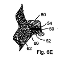
- implant 50 is preferably a tack with a shaft 52 and a head 54.
- Shaft 52 is implanted into hole 66 drilled in the bone, and head 54 captures and holds down the soft tissue 60 being re-attached to bone 62.
Landscapes
- Health & Medical Sciences (AREA)
- Surgery (AREA)
- Life Sciences & Earth Sciences (AREA)
- Orthopedic Medicine & Surgery (AREA)
- Heart & Thoracic Surgery (AREA)
- Animal Behavior & Ethology (AREA)
- Oral & Maxillofacial Surgery (AREA)
- Dentistry (AREA)
- Engineering & Computer Science (AREA)
- Biomedical Technology (AREA)
- Veterinary Medicine (AREA)
- Medical Informatics (AREA)
- Molecular Biology (AREA)
- Nuclear Medicine, Radiotherapy & Molecular Imaging (AREA)
- General Health & Medical Sciences (AREA)
- Public Health (AREA)
- Rheumatology (AREA)
- Surgical Instruments (AREA)
- Prostheses (AREA)
- Diaphragms For Electromechanical Transducers (AREA)
- Polishing Bodies And Polishing Tools (AREA)
Abstract
Description
- This invention relates to a soft tissue repair tool, and more particularly to a tool for preparing soft tissue and bone for implantation of a tissue fastener.
- When a tissue, or a portion of a tissue, is tom away from its bone attachment site, surgery to repair the detached soft tissue is often required. This is often currently done using push-in tack implants which are used to fix tendinous and ligamentous tissue to the bone at the reattachment site. To prepare the tissue for the implant, a hole is made through the soft tissue and into the bone. The implant is subsequently passed through the soft tissue and Into the bone with a portion of the Implant remaining outside the hole to hold the soft tissue against the bone. Because of the need to pass the tack through the soft tissue to be re-attached, most instrument systems include a cannulated drill and guide wire. The drill and guide wire are passed through the tissue together and the drill is then used to make a hole in the bone. The guide wire is left in place in the bone hole to mark its location and provide alignment for placement of the implant. The implant is advanced over the guide wire, with a distal end of the implant passing through the soft tissue and into the bone.
- United States Patent No
5,374,270 discloses a method and device for insertion of a guide pin into bone. The device is provided with a cannulated drill bit and a guide pin, retained releasably within the cannula by means of an adjustable force, for example by mating threads provided on the drill bit and guide pin. In use, the drill bit is removed while leaving the guide pin in place in the bone, so that the guide pin may assist in location of an implant. - According to an aspect of the invention, there is provided a surgical tool according to claim 1.
- Embodiments of this aspect of the invention may include one or more of the following features.
- The member includes a guide wire retainer that receives the guide wire in the friction fit. The member includes a handle and a shaft coupled to the handle. The guide wire has a sharp distal end for penetrating soft tissue and bone. The member has a drill tip for forming a hole in bone. The member defines an internal shoulder which the guide wire pusher contacts to limit relative movement between the member and the guide wire pusher. The member is configured to provide the friction fit such that the guide wire is pre-assembled and secure within the member when the member is being introduced to a surgical site, and the friction fit is overcome when the guide wire is inserted into bone and the member is retracted relative to the guide wire.
- The surgical tool of the present invention, enables a method for advancing a surgical tool to a surgical site, the surgical tool including a member, a guide wire received in the member, and a guide wire pusher, and applying a force to the guide wire pusher to advance the guide wire into bone moving the guide wire relative to the member to overcome a friction fit securing the guide wire to the member.
- Said method may include one or more of the following features.
- The method includes advancing the member relative to the guide wire to form a hole in the bone for receiving an implant. The advancement of the member relative to the guide wire is limited by interaction of the guide wire pusher with the member. The method includes withdrawing the member from the surgical site while maintaining the guide wire at the surgical site by overcoming the friction fit, and advancing an implant over the guide wire and into the bone hole.
- The guide wire retainer provides the friction fit and allows the guide wire to be held in such a way that it is pre-assembled and secure while the tool is being introduced to a surgical site. At the same time, once a hole is drilled into bone, the guide wire retainer allows the remainder of the tool to be removed leaving the guide wire in place at the site. The guide wire pusher allows the guide wire to be impacted into the bone before drilling and limits any possibility of drilling past the end of the guide wire.
- Advantages of the invention may include one or more of the following features.
- A soft tissue repair tool for bone preparation and implant deployment is easy to use, is presented pre-assembled in a single-case, pre-sterilized format, does not require separate assembly and dis-assembly steps, controls the relative position between the guide wire and shaft both before, during, and after drilling, requires only two instrument components, a drill tool and an inserter, to deploy an implant, and can be used arthroscopically or in an open or mini-open procedure.
- The details of one or more embodiments of the invention are set forth in the accompanying drawings and the description below. Other features, objects, and advantages of the invention will be apparent from the description and drawings, and from the claims.
-
-
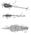
Fig. 1 is a perspective view of a drill tool according to the invention; -
Fig. 2 is a cross-sectional view of the drill tool; -
Fig. 3A is a cross-sectional view of a handle region of the drill tool; -
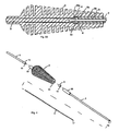
Fig. 3B is a cross-sectional view of the handle region showing a guide wire pusher advanced distally; -
Fig. 4 is an exploded view of the drill tool; -
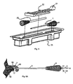
Fig. 5 is an exploded view of a packaged tissue preparation and implant deployment assembly; and -
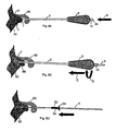
Figs. 6A - 6E show the drill tool in use. - Referring to
Figs. 1 and 2 , a drill tool 1 for preparing tissue to receive an implant includes anelongate member 1a having ashaft 2 and ahandle 3 attached to aproximal region 8 ofshaft 2, e.g., by pressing, gluing or welding. Shaft 2 defines alumen 30, andhandle 3 defines alumen 32.Lumens passage 34 from aproximal end 36 ofhandle 3 to adistal end 7 ofshaft 2. Tool 1 includes aguide wire 4 received withinlumen 30 ofshaft 2 and axially translatable relative toshaft 2, aguide wire pusher 5 received withinlumen 32 ofhandle 3 and axially translatable relative to handle 3, and aguide wire retainer 6 received withinproximal region 8 ofshaft 2 that frictionally engagesguide wire 4, for purposes described below.Guide wire 4 has a distal,sharp point 17 for penetrating soft tissue and bone, and shaftdistal end 7 is formed to asharp drilling tip 7a for forming a hole in bone.Handle 3 has aproximal hex feature 12 that allows releasable attachment of tool 1 to a power drilling tool (not shown). - Referring to
Fig. 3A ,handle 3 has a firstinternal shoulder 10 extending intolumen 32, against whichshaft 2 andguide wire retainer 6 are held, and a secondinternal shoulder 11 extending intolumen 32, which limits the proximal translation of the guide wire pusher 5 (arrow, A) by engagement of an enlarged,distal end 13 ofguide wire pusher 5 withshoulder 11. Guide wire pusherdistal end 13 defines an axially orientedblind hole 15 opening distally for removably receiving aproximal end 18 ofguide wire 4. As shown inFig. 3B ,guide wire pusher 5 is used to distallyadvance guide wire 4 relative toshaft 2. - Referring also to
Fig. 4 , surroundingproximal region 8 ofshaft 2 is an outercylindrical member 38 having an enlargedinner diameter region 38a for receivingguide wire retainer 6. Shaft 2 has aproximal end 8a that abuts againstguide wire retainer 6.Guide wire retainer 6 defines achannel 19 through whichguide wire 4 passes. There is a frictional fit betweenguide wire 4 andguide wire retainer 6 such thatguide wire 4 is retained within tool 1 untilguide wire 4 is fixed in the bone and tool 1 is removed from the bone, as described below. - Referring to
Fig. 5 , tool 1 is preferably packaged sterile with an implant inserter 20 andextra guide wires 21 in a foam carrier 22 (in case theguide wire 4 supplied in tool 1 is damaged during a procedure before all implants for that procedure are implanted) in adisposable tray 23. The components of tool 1 are preferably manufactured by polymer molding processes and machining and pressed assembled, though other methods using biocompatible metal(s) and polymer(s) can be used. - Referring to
Fig. 6A , in use, withguide wire 4 positioned relative toshaft 2 as shown inFig. 1 , i.e., withguide wire pusher 5 againstinternal shoulder 11, the operator passesdistal point 17 ofguide wire 4 anddistal end 7 ofshaft 2 throughsoft tissue 60 and againstbone 62 at thereattachment site 64 on the bone. Referring also toFig. 6B , the operator than impacts guide wire pusher 5 (arrow, B) with, e.g., a hammer, overcoming the friction fit betweenguide wire 4 and guidewire retainer 6 to advanceguide wire 4 relative toshaft 2, until a proximal end 14 ofguide wire pusher 5 is flush with aproximal end 40 ofhandle hex feature 12. This action lodges the distal end ofguide wire 4 in bone 62 a distance equal to the length, I , ofguide wire pusher 5 that extends fromproximal end 40 whenguide wire pusher 5 is againstinternal shoulder 11. - Referring to
Fig. 6C , the operator then advances (arrow, C) and rotates (arrow, D) handle 3 andshaft 2, either by hand or with a power drill coupled tohex feature 12, to form ahole 66 inbone 62 greater than or equal to the length of the portion of the implant to be deployed within the bone. This can be aided by length markings (not shown) onshaft 2. The advancement ofshaft 2 movesshaft 2 relative to guidewire 4 such thatguide wire pusher 5 again protrudes fromproximal end 40 ofhandle 3, and guidewire 4 is retained withinshaft 2 by the friction fit withretainer 6. The operator then gives guide wire pusher 5 a few taps to dislodge any debris which may have become lodged inlumen 30 ofshaft 2. - Referring to
Fig. 6D , the operator then removesshaft 2, handle 3,pusher 5, andretainer 6 from the patient. The friction fit is selected such that the force to overcome the lodgement ofguide wire 4 within the bone is greater than the force to overcome the friction fit, such thatguide wire 4 remains in place in the bone when the remainder of tool 1 is removed. The operator then places animplant 50, such as a Suretac® tissue tack available from Smith & Nephew, Inc., Andover, MA, catalogue number 014567, onguide wire 4, and uses inserter 20 (Fig. 5 ) to pushimplant 50 into the bone. Impaction is usually necessary to aid in this step. The operator then removesguide wire 4 from the bone. - Referring to
Fig. 6E ,implant 50 is preferably a tack with ashaft 52 and ahead 54.Shaft 52 is implanted intohole 66 drilled in the bone, andhead 54 captures and holds down thesoft tissue 60 being re-attached tobone 62. - A number of embodiments of the invention have been described. Nevertheless, it will be understood that various modifications may be made without departing from the scope of the invention. Accordingly, other embodiments are within the scope of the following claims.
Claims (5)
- A surgical tool (1), comprising:a member (1 a) having a drill tip for forming a hole in bone,a guide wire (4) for penetrating soft tissue and bone received within the member (1 a) by a friction fit, anda guide wire pusher (5) for application of a force to the guide wire (4) to overcome the friction fit and advance the guide wire (4) relative to the member (1a): characterised in that the member (1 a) defines an internal shoulder (10) which acts to limit advancement of the guide wire pusher (5) relative to the member (1a), when the guide wire pusher (5) contacts the shoulder (10), in use, to thereby limit a depth to which the member (1a) can be advanced into bone.
- The surgical tool of claim 1 wherein the member includes a guide wire retainer that receives the guide wire in the friction fit.
- The surgical tool of claim 1 wherein the member includes a handle and a shaft coupled to the handle.
- The surgical tool of claim 1 wherein the guide wire has a sharp distal end for penetrating soft tissue and bone.
- The surgical tool of claim 1 wherein the member is configured to provide the friction fit such that the guide wire is pre-assembled and secure within the member when the member is being introduced to a surgical site, and the friction fit is overcome when the guide wire is inserted into bone and the member is retracted relative to the guide wire.
Applications Claiming Priority (3)
| Application Number | Priority Date | Filing Date | Title |
|---|---|---|---|
| US10/184,829 US6955678B2 (en) | 2002-06-28 | 2002-06-28 | Soft tissue repair tool |
| US184829 | 2002-06-28 | ||
| PCT/US2003/019098 WO2004002333A1 (en) | 2002-06-28 | 2003-06-19 | Soft tissue repair tool |
Publications (2)
| Publication Number | Publication Date |
|---|---|
| EP1517643A1 EP1517643A1 (en) | 2005-03-30 |
| EP1517643B1 true EP1517643B1 (en) | 2011-04-06 |
Family
ID=29779464
Family Applications (1)
| Application Number | Title | Priority Date | Filing Date |
|---|---|---|---|
| EP03739167A Expired - Lifetime EP1517643B1 (en) | 2002-06-28 | 2003-06-19 | Soft tissue repair tool |
Country Status (7)
| Country | Link |
|---|---|
| US (1) | US6955678B2 (en) |
| EP (1) | EP1517643B1 (en) |
| JP (2) | JP4764628B2 (en) |
| AT (1) | ATE504244T1 (en) |
| AU (1) | AU2003245542B2 (en) |
| DE (1) | DE60336648D1 (en) |
| WO (1) | WO2004002333A1 (en) |
Families Citing this family (37)
| Publication number | Priority date | Publication date | Assignee | Title |
|---|---|---|---|---|
| AU8047601A (en) | 2000-06-30 | 2002-01-14 | Stephen Ritland | Polyaxial connection device and method |
| US7207992B2 (en) * | 2001-09-28 | 2007-04-24 | Stephen Ritland | Connection rod for screw or hook polyaxial system and method of use |
| AU2003239118B2 (en) | 2002-02-20 | 2007-09-20 | Stephen Ritland | Pedicle screw connector apparatus and method |
| US6966910B2 (en) | 2002-04-05 | 2005-11-22 | Stephen Ritland | Dynamic fixation device and method of use |
| AU2003228960B2 (en) | 2002-05-08 | 2009-06-11 | Stephen Ritland | Dynamic fixation device and method of use |
| JP4598760B2 (en) | 2003-02-25 | 2010-12-15 | リットランド、ステファン | ADJUSTING ROD AND CONNECTOR DEVICE, AND ITS USING METHOD |
| US8262571B2 (en) | 2003-05-22 | 2012-09-11 | Stephen Ritland | Intermuscular guide for retractor insertion and method of use |
| US7455639B2 (en) | 2004-09-20 | 2008-11-25 | Stephen Ritland | Opposing parallel bladed retractor and method of use |
| WO2007012025A2 (en) | 2005-07-19 | 2007-01-25 | Stephen Ritland | Rod extension for extending fusion construct |
| US7959564B2 (en) * | 2006-07-08 | 2011-06-14 | Stephen Ritland | Pedicle seeker and retractor, and methods of use |
| FR2954689B1 (en) * | 2009-12-28 | 2012-12-21 | Sterispine | DEVICE AND METHOD FOR SPINAL SURGERY. |
| US8641717B2 (en) | 2010-07-01 | 2014-02-04 | DePuy Synthes Products, LLC | Guidewire insertion methods and devices |
| US20130123809A1 (en) | 2011-11-11 | 2013-05-16 | VentureMD Innovations, LLC | Transosseous attachment instruments |
| US9131937B2 (en) | 2011-11-16 | 2015-09-15 | VentureMD Innovations, LLC | Suture anchor |
| US10548585B2 (en) | 2011-11-16 | 2020-02-04 | VentureMD Innovations, LLC | Soft tissue attachment |
| US10470756B2 (en) | 2011-11-16 | 2019-11-12 | VentureMD Innovations, LLC | Suture anchor and method |
| US10675014B2 (en) | 2011-11-16 | 2020-06-09 | Crossroads Extremity Systems, Llc | Knotless soft tissue attachment |
| US9687221B2 (en) | 2013-02-13 | 2017-06-27 | Venture MD Innovations, LLC | Method of anchoring a suture |
| US9386997B2 (en) * | 2013-03-29 | 2016-07-12 | Smith & Nephew, Inc. | Tunnel gage |
| US9480520B2 (en) * | 2014-01-23 | 2016-11-01 | Warsaw Orthopedic, Inc. | Surgical instrument and method |
| US10034742B2 (en) | 2014-10-23 | 2018-07-31 | Medos International Sarl | Biceps tenodesis implants and delivery tools |
| US10751161B2 (en) | 2014-10-23 | 2020-08-25 | Medos International Sárl | Biceps tenodesis anchor implants |
| US10729419B2 (en) | 2014-10-23 | 2020-08-04 | Medos International Sarl | Biceps tenodesis implants and delivery tools |
| US10856966B2 (en) | 2014-10-23 | 2020-12-08 | Medos International Sarl | Biceps tenodesis implants and delivery tools |
| US10076374B2 (en) | 2014-10-23 | 2018-09-18 | Medos International Sárl | Biceps tenodesis delivery tools |
| US9693856B2 (en) | 2015-04-22 | 2017-07-04 | DePuy Synthes Products, LLC | Biceps repair device |
| US10154868B2 (en) | 2015-07-17 | 2018-12-18 | Kator, Llc | Transosseous method |
| US9962174B2 (en) | 2015-07-17 | 2018-05-08 | Kator, Llc | Transosseous method |
| US10820918B2 (en) | 2015-07-17 | 2020-11-03 | Crossroads Extremity Systems, Llc | Transosseous guide and method |
| US12383253B2 (en) | 2015-08-04 | 2025-08-12 | Crossroads Extremity Systems, Llc | Suture anchor |
| US10226243B2 (en) | 2015-08-04 | 2019-03-12 | Kator, Llc | Transosseous suture anchor |
| US10117698B2 (en) * | 2016-03-01 | 2018-11-06 | Medos International Sarl | Devices, systems, and methods for driving an anchor into bone |
| US10231824B2 (en) | 2016-04-08 | 2019-03-19 | Medos International Sárl | Tenodesis anchoring systems and tools |
| US10231823B2 (en) | 2016-04-08 | 2019-03-19 | Medos International Sarl | Tenodesis implants and tools |
| JP2019122622A (en) * | 2018-01-17 | 2019-07-25 | 学校法人帝京大学 | Surgical instrument |
| US11026736B2 (en) | 2018-02-19 | 2021-06-08 | Warsaw Orthopedic, Inc. | Surgical instrument and method |
| US11116559B2 (en) | 2018-02-19 | 2021-09-14 | Warsaw Orthopedic, Inc. | Surgical instrument and method |
Family Cites Families (66)
| Publication number | Priority date | Publication date | Assignee | Title |
|---|---|---|---|---|
| US343992A (en) * | 1886-06-22 | Sewing-machine | ||
| US2242003A (en) * | 1940-06-13 | 1941-05-13 | Frank A Lorenzo | Method and apparatus for reduction of fracture of femur |
| US2329398A (en) * | 1941-01-23 | 1943-09-14 | Bernard A Duffy | Screw driver |
| US2414882A (en) * | 1943-09-24 | 1947-01-28 | Herschel Leiter H | Fracture reduction apparatus |
| US2570465A (en) * | 1949-08-01 | 1951-10-09 | Joseph S Lundholm | Means for fixation of hip fractures |
| US3013559A (en) * | 1959-05-06 | 1961-12-19 | Wesley C Thomas | Instrument for closing flesh wounds |
| US3036482A (en) * | 1960-09-02 | 1962-05-29 | Kenworthy Kenneth | Axial-impact type hand tool |
| US3289290A (en) * | 1963-03-14 | 1966-12-06 | Raymond P Sandor | Method and apparatus for installing fasteners |
| FR2165159A5 (en) * | 1971-12-21 | 1973-08-03 | Talan Maryan | |
| US4341206A (en) * | 1978-12-19 | 1982-07-27 | Synthes Ag | Device for producing a hole in a bone |
| SU940376A1 (en) * | 1980-06-05 | 1985-02-07 | Научно-Исследовательская Лаборатория Металлоостеосинтеза С Клиникой Им.Арнольда Сеппо | Screw driver for osteosynthesis |
| US4450835A (en) * | 1981-02-20 | 1984-05-29 | Howmedica, Inc. | Method and system for inserting a surgical wire |
| US4741330A (en) * | 1983-05-19 | 1988-05-03 | Hayhurst John O | Method and apparatus for anchoring and manipulating cartilage |
| SU1097307A1 (en) * | 1983-02-24 | 1984-06-15 | Центральный научно-исследовательский институт травматологии и ортопедии им.Н.Н.Приорова | Screw driver and holder for osteosynthesis |
| US4537185A (en) * | 1983-06-10 | 1985-08-27 | Denis P. Stednitz | Cannulated fixation screw |
| US4573448A (en) * | 1983-10-05 | 1986-03-04 | Pilling Co. | Method for decompressing herniated intervertebral discs |
| IL70736A (en) * | 1984-01-20 | 1988-05-31 | Rosenberg Lior | Self-locking pin device particularly useful for internally fixing bone fractures |
| SE442083B (en) * | 1984-03-14 | 1985-12-02 | Magnus Odensten | DEVICE FOR ALIGNMENT AND CONTROL OF A FRONT AND RELEASABLE DRILLING ROD FOR DRILLING A CIRCULAR HALL IN ATMINSTONE ONE OF TWO KNEELED MAKING RAILS AND LARBES |
| US4744353A (en) * | 1986-04-18 | 1988-05-17 | Mcfarland Joseph R | Method for attaching soft tissue to bone tissue |
| US4895148A (en) | 1986-05-20 | 1990-01-23 | Concept, Inc. | Method of joining torn parts of bodily tissue in vivo with a biodegradable tack member |
| US4924865A (en) * | 1986-05-20 | 1990-05-15 | Concept, Inc. | Repair tack for bodily tissue |
| US5261914A (en) * | 1987-09-02 | 1993-11-16 | Russell Warren | Surgical fastener |
| US4899743A (en) * | 1987-12-15 | 1990-02-13 | Mitek Surgical Products, Inc. | Suture anchor installation tool |
| CN1128944A (en) * | 1988-06-13 | 1996-08-14 | 卡林技术公司 | Apparatus and method for inserting spinal implants |
| US4892148A (en) * | 1988-06-14 | 1990-01-09 | Mason James A | Use of chlorous acid in oil recovery |
| US4950270A (en) * | 1989-02-03 | 1990-08-21 | Boehringer Mannheim Corporation | Cannulated self-tapping bone screw |
| US5129906A (en) * | 1989-09-08 | 1992-07-14 | Linvatec Corporation | Bioabsorbable tack for joining bodily tissue and in vivo method and apparatus for deploying same |
| US5120318A (en) * | 1990-06-25 | 1992-06-09 | Harinathareddy Nallapareddy | Arthroscopy portal maker |
| US5180388A (en) * | 1990-06-28 | 1993-01-19 | American Cyanamid Company | Bone pinning system |
| US5203787A (en) * | 1990-11-19 | 1993-04-20 | Biomet, Inc. | Suture retaining arrangement |
| US5098435A (en) * | 1990-11-21 | 1992-03-24 | Alphatec Manufacturing Inc. | Cannula |
| GB2260585A (en) * | 1991-10-09 | 1993-04-21 | Avdel Systems Ltd | Self-plugging blind rivet |
| US5374270A (en) * | 1991-12-13 | 1994-12-20 | David A. McGuire | Device and method for insertion of guide pin |
| US5167665A (en) * | 1991-12-31 | 1992-12-01 | Mckinney William W | Method of attaching objects to bone |
| US5261887A (en) * | 1992-01-22 | 1993-11-16 | Baxter International Inc. | Easy-to-handle, self-guiding catheter stripper |
| US5320626A (en) | 1992-02-19 | 1994-06-14 | Arthrex Inc. | Endoscopic drill guide |
| US5211647A (en) * | 1992-02-19 | 1993-05-18 | Arthrex Inc. | Interference screw and cannulated sheath for endosteal fixation of ligaments |
| US5415177A (en) * | 1992-12-31 | 1995-05-16 | Zadini; Filiberto P. | Automatic guide wire placement device for intravascular catheters |
| US5295970A (en) * | 1993-02-05 | 1994-03-22 | Becton, Dickinson And Company | Apparatus and method for vascular guide wire insertion with blood flashback containment features |
| US5441502A (en) * | 1993-02-17 | 1995-08-15 | Mitek Surgical Products, Inc. | System and method for re-attaching soft tissue to bone |
| US5423823A (en) * | 1993-02-18 | 1995-06-13 | Arthrex Inc. | Coring reamer |
| US5372599A (en) * | 1993-03-12 | 1994-12-13 | Mitek Surgical Products, Inc. | Surgical anchor and method for deploying the same |
| CA2131141A1 (en) * | 1993-09-24 | 1995-03-25 | James A. Boucher | Ligament graft protection apparatus and method |
| US6241734B1 (en) * | 1998-08-14 | 2001-06-05 | Kyphon, Inc. | Systems and methods for placing materials into bone |
| US5466243A (en) * | 1994-02-17 | 1995-11-14 | Arthrex, Inc. | Method and apparatus for installing a suture anchor through a hollow cannulated grasper |
| US5632745A (en) * | 1995-02-07 | 1997-05-27 | R&D Biologicals, Inc. | Surgical implantation of cartilage repair unit |
| US5569252A (en) * | 1994-09-27 | 1996-10-29 | Justin; Daniel F. | Device for repairing a meniscal tear in a knee and method |
| US5730744A (en) * | 1994-09-27 | 1998-03-24 | Justin; Daniel F. | Soft tissue screw, delivery device, and method |
| JPH08164147A (en) * | 1994-12-14 | 1996-06-25 | Yoshiomi Kuriwaka | Fixing tool for wire for surgical operation |
| US5607432A (en) * | 1995-01-23 | 1997-03-04 | Linvatec Corporation | Threaded suture anchor retriever |
| US6235057B1 (en) * | 1995-01-24 | 2001-05-22 | Smith & Nephew, Inc. | Method for soft tissue reconstruction |
| US5782835A (en) * | 1995-03-07 | 1998-07-21 | Innovasive Devices, Inc. | Apparatus and methods for articular cartilage defect repair |
| US6197001B1 (en) * | 1996-09-27 | 2001-03-06 | Becton Dickinson And Company | Vascular access device |
| US5928252A (en) * | 1997-01-21 | 1999-07-27 | Regen Biologics, Inc. | Device and method for driving a needle and meniscal repair |
| US5918604A (en) * | 1997-02-12 | 1999-07-06 | Arthrex, Inc. | Method of loading tendons into the knee |
| US5895389A (en) * | 1997-05-29 | 1999-04-20 | Synthes (U.S.A.) | Drilling guide and measuring instrumentation |
| US5954732A (en) * | 1997-09-10 | 1999-09-21 | Hart; Charles C. | Suturing apparatus and method |
| US5871504A (en) * | 1997-10-21 | 1999-02-16 | Eaton; Katulle Koco | Anchor assembly and method for securing ligaments to bone |
| US5976127A (en) * | 1998-01-14 | 1999-11-02 | Lax; Ronald | Soft tissue fixation devices |
| DE19859135B4 (en) * | 1998-12-21 | 2006-07-13 | Ferton Holding S.A. | Device for driving a wire pin, in particular a Kirschner wire, in bone material |
| US6270503B1 (en) * | 1999-02-03 | 2001-08-07 | Arthrex, Inc. | System for ostechondral flap repair and method |
| US6402757B1 (en) * | 1999-03-12 | 2002-06-11 | Biomet, Inc. | Cannulated fastener system for repair of bone fracture |
| JP4898993B2 (en) | 2000-01-28 | 2012-03-21 | クック メディカル テクノロジーズ エルエルシー | Intravascular medical device with multiple wires |
| US6375658B1 (en) * | 2000-04-28 | 2002-04-23 | Smith & Nephew, Inc. | Cartilage grafting |
| US6613017B1 (en) * | 2000-08-08 | 2003-09-02 | Scimed Life Systems, Inc. | Controlled depth injection device and method |
| US6451023B1 (en) * | 2001-01-25 | 2002-09-17 | Linvatec Corporation | Guide bushing for coring reamer, storage package for reamer assembly, and method of use |
-
2002
- 2002-06-28 US US10/184,829 patent/US6955678B2/en not_active Expired - Lifetime
-
2003
- 2003-06-19 WO PCT/US2003/019098 patent/WO2004002333A1/en not_active Ceased
- 2003-06-19 DE DE60336648T patent/DE60336648D1/en not_active Expired - Lifetime
- 2003-06-19 AT AT03739167T patent/ATE504244T1/en not_active IP Right Cessation
- 2003-06-19 EP EP03739167A patent/EP1517643B1/en not_active Expired - Lifetime
- 2003-06-19 JP JP2004517661A patent/JP4764628B2/en not_active Expired - Fee Related
- 2003-06-19 AU AU2003245542A patent/AU2003245542B2/en not_active Ceased
-
2011
- 2011-04-05 JP JP2011083887A patent/JP2011183168A/en active Pending
Also Published As
| Publication number | Publication date |
|---|---|
| EP1517643A1 (en) | 2005-03-30 |
| WO2004002333A1 (en) | 2004-01-08 |
| AU2003245542A1 (en) | 2004-01-19 |
| DE60336648D1 (en) | 2011-05-19 |
| JP4764628B2 (en) | 2011-09-07 |
| US20040002709A1 (en) | 2004-01-01 |
| JP2011183168A (en) | 2011-09-22 |
| ATE504244T1 (en) | 2011-04-15 |
| JP2005531364A (en) | 2005-10-20 |
| AU2003245542B2 (en) | 2008-11-20 |
| US6955678B2 (en) | 2005-10-18 |
Similar Documents
| Publication | Publication Date | Title |
|---|---|---|
| EP1517643B1 (en) | Soft tissue repair tool | |
| US7588595B2 (en) | Graft fixation device and method | |
| US5733289A (en) | Ligament graft harvesting | |
| AU2013277412B2 (en) | Modular reamer retrograde attachment | |
| US8388621B2 (en) | Retrodrill system | |
| EP0834280B1 (en) | Tissue fastener implantation apparatus | |
| US8398685B2 (en) | Transbuccal plate holding cannula | |
| EP1785103B1 (en) | Apparatus for anterior cruciate ligament (ACL) reconstruction using rotary drill cutter to form retrograde sockets | |
| US7160305B2 (en) | Retrodrill technique for insertion of autograft, allograft or synthetic osteochondral implants | |
| EP1484022A3 (en) | Push-in suture anchor, insertion tool, and method for inserting a push-in suture anchor | |
| US20130030478A1 (en) | Anchor wire system and method | |
| AU4947200A (en) | Bone suturing device | |
| EP3376972B1 (en) | Surgical tunneling instrument with expandable section | |
| US10085736B2 (en) | Hollow body anchor | |
| KR20210115209A (en) | femoral headless nephrotectomy apparatus |
Legal Events
| Date | Code | Title | Description |
|---|---|---|---|
| PUAI | Public reference made under article 153(3) epc to a published international application that has entered the european phase |
Free format text: ORIGINAL CODE: 0009012 |
|
| 17P | Request for examination filed |
Effective date: 20041203 |
|
| AK | Designated contracting states |
Kind code of ref document: A1 Designated state(s): AT BE BG CH CY CZ DE DK EE ES FI FR GB GR HU IE IT LI LU MC NL PT RO SE SI SK TR |
|
| AX | Request for extension of the european patent |
Extension state: AL LT LV MK |
|
| DAX | Request for extension of the european patent (deleted) | ||
| 17Q | First examination report despatched |
Effective date: 20071004 |
|
| GRAP | Despatch of communication of intention to grant a patent |
Free format text: ORIGINAL CODE: EPIDOSNIGR1 |
|
| GRAS | Grant fee paid |
Free format text: ORIGINAL CODE: EPIDOSNIGR3 |
|
| GRAA | (expected) grant |
Free format text: ORIGINAL CODE: 0009210 |
|
| AK | Designated contracting states |
Kind code of ref document: B1 Designated state(s): AT BE BG CH CY CZ DE DK EE ES FI FR GB GR HU IE IT LI LU MC NL PT RO SE SI SK TR |
|
| REG | Reference to a national code |
Ref country code: GB Ref legal event code: FG4D |
|
| REG | Reference to a national code |
Ref country code: CH Ref legal event code: EP |
|
| REG | Reference to a national code |
Ref country code: IE Ref legal event code: FG4D |
|
| REF | Corresponds to: |
Ref document number: 60336648 Country of ref document: DE Date of ref document: 20110519 Kind code of ref document: P |
|
| REG | Reference to a national code |
Ref country code: DE Ref legal event code: R096 Ref document number: 60336648 Country of ref document: DE Effective date: 20110519 |
|
| REG | Reference to a national code |
Ref country code: NL Ref legal event code: T3 |
|
| PG25 | Lapsed in a contracting state [announced via postgrant information from national office to epo] |
Ref country code: SI Free format text: LAPSE BECAUSE OF FAILURE TO SUBMIT A TRANSLATION OF THE DESCRIPTION OR TO PAY THE FEE WITHIN THE PRESCRIBED TIME-LIMIT Effective date: 20110406 |
|
| PG25 | Lapsed in a contracting state [announced via postgrant information from national office to epo] |
Ref country code: SE Free format text: LAPSE BECAUSE OF FAILURE TO SUBMIT A TRANSLATION OF THE DESCRIPTION OR TO PAY THE FEE WITHIN THE PRESCRIBED TIME-LIMIT Effective date: 20110406 Ref country code: PT Free format text: LAPSE BECAUSE OF FAILURE TO SUBMIT A TRANSLATION OF THE DESCRIPTION OR TO PAY THE FEE WITHIN THE PRESCRIBED TIME-LIMIT Effective date: 20110808 |
|
| PG25 | Lapsed in a contracting state [announced via postgrant information from national office to epo] |
Ref country code: FI Free format text: LAPSE BECAUSE OF FAILURE TO SUBMIT A TRANSLATION OF THE DESCRIPTION OR TO PAY THE FEE WITHIN THE PRESCRIBED TIME-LIMIT Effective date: 20110406 Ref country code: AT Free format text: LAPSE BECAUSE OF FAILURE TO SUBMIT A TRANSLATION OF THE DESCRIPTION OR TO PAY THE FEE WITHIN THE PRESCRIBED TIME-LIMIT Effective date: 20110406 Ref country code: CY Free format text: LAPSE BECAUSE OF FAILURE TO SUBMIT A TRANSLATION OF THE DESCRIPTION OR TO PAY THE FEE WITHIN THE PRESCRIBED TIME-LIMIT Effective date: 20110406 Ref country code: ES Free format text: LAPSE BECAUSE OF FAILURE TO SUBMIT A TRANSLATION OF THE DESCRIPTION OR TO PAY THE FEE WITHIN THE PRESCRIBED TIME-LIMIT Effective date: 20110717 Ref country code: GR Free format text: LAPSE BECAUSE OF FAILURE TO SUBMIT A TRANSLATION OF THE DESCRIPTION OR TO PAY THE FEE WITHIN THE PRESCRIBED TIME-LIMIT Effective date: 20110707 |
|
| PG25 | Lapsed in a contracting state [announced via postgrant information from national office to epo] |
Ref country code: EE Free format text: LAPSE BECAUSE OF FAILURE TO SUBMIT A TRANSLATION OF THE DESCRIPTION OR TO PAY THE FEE WITHIN THE PRESCRIBED TIME-LIMIT Effective date: 20110406 Ref country code: CZ Free format text: LAPSE BECAUSE OF FAILURE TO SUBMIT A TRANSLATION OF THE DESCRIPTION OR TO PAY THE FEE WITHIN THE PRESCRIBED TIME-LIMIT Effective date: 20110406 |
|
| REG | Reference to a national code |
Ref country code: CH Ref legal event code: PL |
|
| PLBE | No opposition filed within time limit |
Free format text: ORIGINAL CODE: 0009261 |
|
| STAA | Information on the status of an ep patent application or granted ep patent |
Free format text: STATUS: NO OPPOSITION FILED WITHIN TIME LIMIT |
|
| PG25 | Lapsed in a contracting state [announced via postgrant information from national office to epo] |
Ref country code: SK Free format text: LAPSE BECAUSE OF FAILURE TO SUBMIT A TRANSLATION OF THE DESCRIPTION OR TO PAY THE FEE WITHIN THE PRESCRIBED TIME-LIMIT Effective date: 20110406 Ref country code: RO Free format text: LAPSE BECAUSE OF FAILURE TO SUBMIT A TRANSLATION OF THE DESCRIPTION OR TO PAY THE FEE WITHIN THE PRESCRIBED TIME-LIMIT Effective date: 20110406 Ref country code: DK Free format text: LAPSE BECAUSE OF FAILURE TO SUBMIT A TRANSLATION OF THE DESCRIPTION OR TO PAY THE FEE WITHIN THE PRESCRIBED TIME-LIMIT Effective date: 20110406 |
|
| 26N | No opposition filed |
Effective date: 20120110 |
|
| REG | Reference to a national code |
Ref country code: IE Ref legal event code: MM4A |
|
| PG25 | Lapsed in a contracting state [announced via postgrant information from national office to epo] |
Ref country code: CH Free format text: LAPSE BECAUSE OF NON-PAYMENT OF DUE FEES Effective date: 20110630 Ref country code: IE Free format text: LAPSE BECAUSE OF NON-PAYMENT OF DUE FEES Effective date: 20110619 Ref country code: LI Free format text: LAPSE BECAUSE OF NON-PAYMENT OF DUE FEES Effective date: 20110630 |
|
| REG | Reference to a national code |
Ref country code: DE Ref legal event code: R097 Ref document number: 60336648 Country of ref document: DE Effective date: 20120110 |
|
| PG25 | Lapsed in a contracting state [announced via postgrant information from national office to epo] |
Ref country code: MC Free format text: LAPSE BECAUSE OF NON-PAYMENT OF DUE FEES Effective date: 20110630 |
|
| PG25 | Lapsed in a contracting state [announced via postgrant information from national office to epo] |
Ref country code: LU Free format text: LAPSE BECAUSE OF NON-PAYMENT OF DUE FEES Effective date: 20110619 |
|
| PG25 | Lapsed in a contracting state [announced via postgrant information from national office to epo] |
Ref country code: BG Free format text: LAPSE BECAUSE OF FAILURE TO SUBMIT A TRANSLATION OF THE DESCRIPTION OR TO PAY THE FEE WITHIN THE PRESCRIBED TIME-LIMIT Effective date: 20110706 |
|
| PG25 | Lapsed in a contracting state [announced via postgrant information from national office to epo] |
Ref country code: TR Free format text: LAPSE BECAUSE OF FAILURE TO SUBMIT A TRANSLATION OF THE DESCRIPTION OR TO PAY THE FEE WITHIN THE PRESCRIBED TIME-LIMIT Effective date: 20110406 |
|
| PG25 | Lapsed in a contracting state [announced via postgrant information from national office to epo] |
Ref country code: HU Free format text: LAPSE BECAUSE OF FAILURE TO SUBMIT A TRANSLATION OF THE DESCRIPTION OR TO PAY THE FEE WITHIN THE PRESCRIBED TIME-LIMIT Effective date: 20110406 |
|
| PGFP | Annual fee paid to national office [announced via postgrant information from national office to epo] |
Ref country code: GB Payment date: 20140618 Year of fee payment: 12 |
|
| PGFP | Annual fee paid to national office [announced via postgrant information from national office to epo] |
Ref country code: DE Payment date: 20140611 Year of fee payment: 12 Ref country code: IT Payment date: 20140606 Year of fee payment: 12 |
|
| PGFP | Annual fee paid to national office [announced via postgrant information from national office to epo] |
Ref country code: NL Payment date: 20140610 Year of fee payment: 12 Ref country code: BE Payment date: 20140611 Year of fee payment: 12 |
|
| PGFP | Annual fee paid to national office [announced via postgrant information from national office to epo] |
Ref country code: FR Payment date: 20140609 Year of fee payment: 12 |
|
| REG | Reference to a national code |
Ref country code: DE Ref legal event code: R119 Ref document number: 60336648 Country of ref document: DE |
|
| PG25 | Lapsed in a contracting state [announced via postgrant information from national office to epo] |
Ref country code: IT Free format text: LAPSE BECAUSE OF NON-PAYMENT OF DUE FEES Effective date: 20150619 |
|
| GBPC | Gb: european patent ceased through non-payment of renewal fee |
Effective date: 20150619 |
|
| REG | Reference to a national code |
Ref country code: NL Ref legal event code: MM Effective date: 20150701 |
|
| REG | Reference to a national code |
Ref country code: FR Ref legal event code: ST Effective date: 20160229 |
|
| PG25 | Lapsed in a contracting state [announced via postgrant information from national office to epo] |
Ref country code: GB Free format text: LAPSE BECAUSE OF NON-PAYMENT OF DUE FEES Effective date: 20150619 Ref country code: DE Free format text: LAPSE BECAUSE OF NON-PAYMENT OF DUE FEES Effective date: 20160101 Ref country code: NL Free format text: LAPSE BECAUSE OF NON-PAYMENT OF DUE FEES Effective date: 20150701 |
|
| PG25 | Lapsed in a contracting state [announced via postgrant information from national office to epo] |
Ref country code: FR Free format text: LAPSE BECAUSE OF NON-PAYMENT OF DUE FEES Effective date: 20150630 |
|
| PG25 | Lapsed in a contracting state [announced via postgrant information from national office to epo] |
Ref country code: BE Free format text: LAPSE BECAUSE OF NON-PAYMENT OF DUE FEES Effective date: 20150630 |