This application claims priority to prior Japanese patent application JP
2003-328298, the disclosure of which is incorporated herein by reference.
Background of the Invention:
This invention relates to a hinge unit widely used in various fields.
For example, a hinge unit incorporated into a mobile telephone set is
disclosed in Japanese patent publications (JP-B) Nos. 3145652 and 3220412.
The hinge unit mechanically and rotatably connects an operating part and a
display part of the mobile telephone set so that the display part can be opened,
for example, to an angle of 180° with respect to the operating part. The display
part and the operating part are electrically connected by a cable independently
from the mechanical connection by the hinge unit.
However, the above-mentioned hinge unit is disadvantageous in that a
large number of parts are required and assembling is complicated because the
electrical connection and the mechanical connection between the operating part
and the display part are separately provided.
Summary of the Invention:
It is therefore an object of this invention to provide a hinge unit requiring
a reduced number of parts and simple in assembling.
Other object of the present invention will become clear as the
description proceeds.
According to an aspect of the present invention, there is provided a
hinge unit for use in an electronic apparatus, said hinge unit comprising a shaft,
a first member holding a part of said shaft, said first member unrotatable and
axially unmovable with respect to said shaft, a circuit board having a flexible
portion wound around the other part of said shaft, a second member rotatable
and axially unmovable with respect to said shaft, an intermediate member faced
to said second member in an axial direction, said intermediate member being
unrotatable and axially movable with respect to said shaft, an elastic member
interposed between said shaft and said intermediate member and urging said
intermediate member towards said second member in the axial direction, and
an engaging structure engaging said second member and said intermediate
member with each other in a rotating direction, said engaging structure
releasing the engagement between said second member and said intermediate
member with energization of said elastic member in response to a rotating force
applied between said second member and said intermediate member.
Brief Description of the Drawing:
Fig. 1A is a perspective view for describing a first step of fitting, to an
electronic apparatus, a hinge unit according to an embodiment of this invention;
Fig. 1B is a perspective view of a second step of fitting the hinge unit to
the electronic apparatus;
Fig. 2A is a front perspective view of the electronic apparatus with the
hinge unit fitted thereto, wherein the electronic apparatus is in an initial state;
Fig. 2B is a rear perspective view corresponding to Fig. 2A;
Fig. 2C is a front perspective view of the electronic apparatus with the
hinge unit fitted thereto, wherein the electronic apparatus is in an operated
state;
Fig. 2D is a rear perspective view corresponding to Fig. 2C;
Fig. 3 is an exploded perspective view of the hinge unit and a camera
module to be connected thereto;
Fig. 4A is a perspective view of a shaft included in the hinge unit;
Fig. 4B is a perspective view of a circuit board (FPC) included in the
hinge unit;
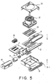
Fig. 5 is a perspective view for describing a first assembling step of the
hinge unit;
Fig. 6 is a perspective view for describing a second assembling step of
the hinge unit;
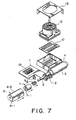
Fig. 7 is a perspective view for describing a third assembling step of the
hinge unit;
Fig. 8 is a perspective view for describing a fourth assembling step of
the hinge unit;
Fig. 9 is a perspective view for describing a fifth assembling step of the
hinge unit;
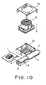
Fig. 10 is a perspective view for describing a sixth assembling step of
the hinge unit;
Fig. 11 is a perspective view for describing a seventh assembling step
of the hinge unit;
Fig. 12 is a perspective view of the hinge unit after completion of the
assembling steps;
Fig. 13A is an enlarged perspective view of a part of the shaft illustrated
in Fig. 4A;
Fig. 13B is an enlarged perspective view of a cap included in the hinge
unit, as seen from one side;
Fig. 13C is an enlarged perspective view of the cap as seen from the
other side;
Fig. 13D is an enlarged perspective view of a third shell element
included in the hinge unit;
Fig. 14A is an enlarged perspective view of a first shell element
included in the hinge unit;
Fig. 14B is an enlarged perspective view of a second shell element
included in the hinge unit;
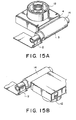
Fig. 15A is an enlarged perspective view showing a relaxed state of a
flexible part of the FPC when the camera module is in an initial state;
Fig. 15B is an enlarged perspective view showing a stretched state of
the flexible part of the FPC when the camera module is in a 180°-rotated state;
Fig. 16A is an enlarged perspective sectional view of the hinge unit
when the camera module is in the initial state or in the 180°-rotated state;
Fig. 16B is an enlarged perspective sectional view similar to Fig. 16A
except that the shaft is removed;
Fig. 16C is an enlarged perspective sectional view of the hinge unit
when the camera module is rotated by about 20° from the initial state or the
180°-rotated state; and
Fig. 16D is an enlarged perspective sectional view similar to Fig. 16C
except that the shaft is removed.
Description of the Preferred Embodiments:
Now, description will be made as regards a hinge unit according to an
embodiment of this invention. The hinge unit can be used in a camera-equipped
electronic apparatus.
At first referring to Figs. 1 A, 1B, and 2A to 2D, the description will be
made as regards a whole of the camera-equipped electronic apparatus in order
to facilitate an understanding of this invention. Referring to Figs. 1A and 1 B, a
camera module 12 as a first apparatus element is incorporated into an
electronic apparatus 19 as a second apparatus element by the use of a hinge
unit 14. As shown in Fig. 1A, the hinge unit 14 with the camera module 12
preliminarily attached thereto is clamped by an upper protector 15 and a lower
protector 16 from upper and lower sides thereof, respectively. Next, as
illustrated in Fig. 1B, the hinge unit 14 is clamped by upper and lower support
portions 17-1 and 18-1 of upper and lower main bodies 17 and 18 of the
electronic apparatus 19 from the upper and the lower sides thereof, respectively.
In the above-mentioned manner, the camera module 12 is rotatably
attached to the electronic apparatus 19 via the hinge unit 14 as illustrated in
Figs. 2A and 2B. In Figs. 2C and 2D, the camera module 12 is rotated by 180°.
The lower main body 18 has a surface provided with a display portion,
such as a LCD, and an operating portion 18-2. By manipulating the operating
portion 18-2, a front view and a user himself can be photographed as an object
in the state illustrated in Figs. 2A and 2B and in the state illustrated in Figs. 2C
and 2D, respectively, while confirming the object at the display portion.
Next referring to Fig. 3, various components of the hinge unit 14 will be
described.
The hinge unit 14 comprises a flexible board (FPC) 1 as a circuit board,
a shaft 2, a first shell element 3, a second shell element 4, a stopper 5, a coil
spring 6, a cap 7, a third shell element 8, and a E-shaped snap ring 9.
Assembling of the hinge unit 14 will later be described in detail.
To the hinge unit 14, press-connecting-type connectors 10 and 11, the
camera module 12, a fitting metal 13, and a board-to-board connector 15 are
combined. Thus, the hinge unit 14 with the camera module 12 preliminarily
attached thereto is produced.
Referring to Fig. 4A, the shaft 2 has a first rotation stopper 2-1 having a
rectangular flange-like shape and formed in the vicinity of one end of the shaft 2.
The shaft 2 has a second rotation stopper 2-2 (which will later be described)
formed at a distance from the other end of the shaft 2.
Referring to Fig. 4B, the flexible board 1 has a double-sided tape 1-1
preliminarily adhered to its one end. By the double-sided tape 1-1, the flexible
board 1 is fixed to the shaft 2 between the first and the second rotation stoppers
2-1 and 2-2. The flexible board 1 further has a bendable portion 1-2 as a
flexible portion, a fixed portion 1-3, a connector fitting portion 1-4, and a shield
layer 1-5. The bendable portion 1-2 is wound around the shaft 2 in a plurality
of turns.
Referring to Figs. 5 to 12, description will be made of a series of
assembling steps of an assembly of the camera module 12 and the hinge unit
14.
At first, the shaft 2 with the FPC 1 wound around and fixed thereto is
clamped and fixed by the first and the second shell elements 3 and 4 as
depicted by arrows in Fig. 5. A combination of the first and the second shell
elements 3 and 4 will be called a first member. The first member is provided
with a rotation stopper 3-1. The rotation stopper 3-1 is engaged with the first
rotation stopper 2-1 of the shaft 2 so that the first member is unrotatable with
respect to the shaft 2. The first rotation stopper 2-1 of the shaft 2 is engaged
with the first and the second shell elements 3 and 4 also in an axial direction so
that the first member is axially unmovable with respect to the shaft 2.
The stopper 5 is attached to the fixing portion 1-3 of the FPC 1 as
depicted by an arrow in Fig. 6. The board-to-board connector 15 is attached to
the connector fitting portion 1-4 of the FPC 1. In most cases, the board-to-board
connector 15 is preliminarily soldered and connected to the connector
fitting portion 1-4 of the FPC 1 prior to the assembling steps.
To the shaft 2, the coil spring 6 as an elastic member, the cylindrical cap
7 as an intermediate member covering the coil spring 6, and the third shell
element 8 of a tubular shape are successively attached as depicted by arrows
in Fig. 7. Further, the E-shaped snap ring 9 is attached to the shaft 2 as
depicted by an arrow in Fig. 8 so as to prevent the third shell element 8 from
being released form the shaft 2. Thus, the third shell element 8 is rotatable
and axially unmovable with respect to the shaft 2. Therefore, the third shell
element 8 is rotatable with respect to the first member comprising the first and
the second shell elements 3 and 4. The third shell element 8 may be called a
second member.
Referring to Figs. 7 and 8 in combination, the cap 7 is inserted into the
interior of the third shell element 8. The coil spring 6 is disposed inside the cap
7. The cap 7 is provided with an inward flange 7-1 formed at a first axial end
thereof. The coil spring 6 is interposed between the inward flange 7-1 and the
second rotation stopper 2-2 in a compressed state. In this state, the cap 7 is
urged by a restoring force of the coil spring 6 towards an axial end plate 8-1
which is provided at a first axial end of the third shell element 8. The third shell
element 8 has a cover portion 8-2 extending in the axial direction so as to cover
not only the cap 7 and the coil spring 6 but also the bendable portion 1-2 of the
flexible board 1.
As depicted by an arrow in Fig. 9, the press-connecting-type connector
10 is inserted into the first shell element 3. At this time, the press-connecting-type
connector 11 of a different type illustrated in Fig. 3 may be used.
Thereafter, the camera module 12 is inserted into the first shell element 3 as
depicted by an arrow in Fig. 10.
Finally, as depicted by an arrow in Fig. 11, the fixing metal 13 is
attached to the first shell element 3. Thus, the hinge unit 14 with the camera
module 12 is completed as illustrated in Fig. 12.
Further referring to Figs. 13A to 13D, 14A, and 14B, description will be
made of a detailed structure of the hinge unit 14.
The second rotation stopper 2-2 of the shaft 2 is formed into a non-circular
flange-like shape as illustrated in Fig. 13A. The cap 7 is provided with
a mating rotation stopper 7-2 formed on an inner surface of an opening which is
opened at a second axial end of the cap 7. The mating rotation stopper 7-2
has a non-cylindrical surface substantially equivalent to an outer peripheral
surface of the second rotation stopper 2-2 of the shaft 2. The mating rotation
stopper 7-2 of the cap 7 is snuggly fitted over the second rotation stopper 2-2 of
the shaft 2 so that the cap 7 is unrotatable and axially movable with respect to
the shaft 2.
As illustrated in Fig. 13C, the cap 7 is provided with the inward flange 7-1
formed at the first axial end as described above. The inward flange 7-1 has
an outer surface provided with a depressed portion 7-3 extending in a radial
direction. The depressed portion 7-3 is defined by a pair of side walls inclined
so that an opening of the depressed portion 7-3 is wider than a bottom thereof
in section.
On the other hand, as illustrated in Fig. 13D, the axial end plate 8-1 of
the third shell element 8 is provided with a protruding portion 8-3 formed on its
inner surface and extending in the radial direction. The protruding portion 8-3
has a shape adapted to be substantially tightly fitted to the depressed portion 7-3
in the axial direction. When fitted to each other, the protruding portion 8-3
and the depressed portion 7-3 form an engaging structure for engaging the third
shell element 8 and the cap 7 with each other in a rotating direction. When a
rotating force not smaller than a predetermined value is applied between the
third shell element 8 and the cap 7, the engaging structure releases the
engagement between the third shell element 8 and the cap 7 with energization
of the coil spring 6, as will later be described in detail. In order to provide the
rotating force, the third shell element 8 has an outer peripheral surface of a non-circular
shape and is prevented from rotation with respect to the electronic
apparatus.
The third shell element 8 is provided with a stopper 8-4 at a second
axial end thereof as shown in Fig. 13D. As shown in Figs. 14A and 14B, the
first and the second shell elements 3 and 4 are provided with stoppers 3-2 and
4-2 which limit a rotation angle of the third shell element 8 in cooperation with
the stopper 8-4, By selecting locations of the stoppers 3-2, 4-2, and 8-4, the
rotation angle can be changed. Herein, the rotation angle is set at 180°.
Referring to Fig. 15A, the camera module 12 is in an initial state (i.e.,
the camera module 12 is received in an inner space, in other words, the camera
module 12 is held at a front view photographing position). Referring to Fig.
15B, the camera module 12 is rotated by 180° (i.e., the camera module 12 is
protruded, in other words, the camera module 12 is held at a self image
photographing position). In Fig. 15A, the bendable portion 1-2 of the FPC 1 is
relaxed. In Fig. 15B, the bendable portion 1-2 is stretched.
Referring to Fig. 16A, a rotation brake portion and a click portion are
shown in the state where the camera module 12 is in the initial state or the
180°-rotated state. In Fig. 16B, the shaft 2 is removed from the state in Fig.
16A. In Fig. 16C, the rotation brake portion and the click portion are shown in
the state where the camera module 12 is rotated by about 20° from the initial
state or the 180°-rotated state. In Fig. 16D, the shaft 2 is removed from the
state in Fig. 16C.
In the states illustrated in Figs. 16A and 16B, the protruding portion 8-3
formed inside the third shell element 8 and the depressed portion 7-3 of the cap
7 are fitted to each other. Since the first shell element 3 is fixed to the shaft 2,
the shaft 2 is rotated when the camera module 12 is rotated. Since the cap 7
is inhibited from rotation with respect to the shaft 2, the cap 7 is rotated together
with the shaft 2. However, the cap 7 is slidable in the axial direction.
Therefore, as illustrated in Figs. 16C and 16D, when the cap 7 starts rotation
following the rotation of the shaft 2, the depressed portion 7-3 of the cap 7 is
disengaged from the protruding portion 8-3 of the third shell element 8.
Further, the cap 7 is moved in the axial direction away from the axial end plate
8-1 of the third shell element 8 to press the coil spring 6 against the second
rotation stopper 2-2 of the shaft 2. Therefore, a frictional resistance produced
between the coil spring 6 and the second rotation stopper 2-2 serves as a
rotation brake so that the camera module 12 is prevented from being rotated
due to its weight. In this event, a combination of the coil spring 6 and the
second rotation stopper 2-2 will be referred to as the rotation brake portion.
Returning from the state illustrated in Figs. 16C and 16D to the state
illustrated in Figs. 16A and 16B, the depressed portion 7-3 of the cap 7 is faced
to the protruding portion 8-3 of the third shell element 8 and the cap 7 is pushed
back by the coil spring 6. As a consequence, the depressed portion 7-3 of the
cap 7 is fitted again over the protruding portion 8-3 of the third shell element 8.
At this time, appropriate click feeling is obtained. In this event, a combination
of the coil spring 6, the depressed portion 7-3, and the protruding portion 8-3
will be referred to as the click portion.
In this state also, the coil spring 6 is not unloaded but compressed.
The camera module 12 is kept in the initial state or the 180°-rotated state by a
force which is required for the depressed portion 7-3 of the cap 7 to move
across the protruding portion 8-3 of the third shell 8.
As will presently be described, the above-mentioned hinge unit 14 may
easily be provided with EMC protection. Specifically, a shell forming member,
such as the first, the second, and the third shell elements 3, 4, 8, is made of a
metal or a resin with a metal film formed on its surface. On the other hand, as
shown in Fig. 4B, the FPC 1 is provided with a shield layer 1-5 of conductive
material at a portion exposed outward from the shell forming member. The
shield layer 1-5 continuously extends to the fixing portion 1-3 and electrically
connected to the shell forming member. With this structure, the bendable
portion 1-2 of the FPC 1 requires no shield layer. Therefore, the FPC 1 can be
reduced in thickness so that an appropriate flexibility or bendability is
maintained.
While this invention has thus far been described in connection with the
preferred embodiment thereof, it will be readily possible for those skilled in the
art to put this invention into practice in various other manners without departing
from the scope set forth in the appended claims. In the foregoing, the hinge
unit with the camera module has been described. Alternatively, board-to-board
connectors may be mounted on opposite ends of the FPC without mounting the
camera module. In this case, the other end of the FPC has a similar structure.
The hinge unit is applicable not only to the camera-equipped electronic
apparatus but also to various other electronic apparatuses such as a mobile
telephone, a personal digital assistant (PDA), and a notebook-type personal
computer.