EP1517455A1 - Transmission power control method for cross-polarized signals - Google Patents
Transmission power control method for cross-polarized signals Download PDFInfo
- Publication number
- EP1517455A1 EP1517455A1 EP03425608A EP03425608A EP1517455A1 EP 1517455 A1 EP1517455 A1 EP 1517455A1 EP 03425608 A EP03425608 A EP 03425608A EP 03425608 A EP03425608 A EP 03425608A EP 1517455 A1 EP1517455 A1 EP 1517455A1
- Authority
- EP
- European Patent Office
- Prior art keywords
- contr
- power
- opt
- transmission
- rain
- Prior art date
- Legal status (The legal status is an assumption and is not a legal conclusion. Google has not performed a legal analysis and makes no representation as to the accuracy of the status listed.)
- Granted
Links
- 230000005540 biological transmission Effects 0.000 title claims abstract description 68
- 238000000034 method Methods 0.000 title claims description 18
- 238000005562 fading Methods 0.000 claims description 17
- 238000012937 correction Methods 0.000 claims description 7
- 238000005388 cross polarization Methods 0.000 claims description 5
- 238000001914 filtration Methods 0.000 claims description 3
- GZPBVLUEICLBOA-UHFFFAOYSA-N 4-(dimethylamino)-3,5-dimethylphenol Chemical compound CN(C)C1=C(C)C=C(O)C=C1C GZPBVLUEICLBOA-UHFFFAOYSA-N 0.000 claims description 2
- 238000012935 Averaging Methods 0.000 claims 2
- 238000002955 isolation Methods 0.000 abstract description 4
- 230000010287 polarization Effects 0.000 description 53
- 230000028161 membrane depolarization Effects 0.000 description 13
- 230000006872 improvement Effects 0.000 description 8
- 230000036961 partial effect Effects 0.000 description 7
- 238000010586 diagram Methods 0.000 description 6
- 238000013459 approach Methods 0.000 description 5
- 230000003068 static effect Effects 0.000 description 5
- 230000006735 deficit Effects 0.000 description 4
- 230000007246 mechanism Effects 0.000 description 4
- 230000003044 adaptive effect Effects 0.000 description 3
- 230000008901 benefit Effects 0.000 description 3
- 238000006243 chemical reaction Methods 0.000 description 3
- 230000000670 limiting effect Effects 0.000 description 3
- 230000015556 catabolic process Effects 0.000 description 2
- 238000006731 degradation reaction Methods 0.000 description 2
- 238000013461 design Methods 0.000 description 2
- 238000009826 distribution Methods 0.000 description 2
- 230000000694 effects Effects 0.000 description 2
- 230000002452 interceptive effect Effects 0.000 description 2
- 238000001556 precipitation Methods 0.000 description 2
- 238000011084 recovery Methods 0.000 description 2
- 230000002829 reductive effect Effects 0.000 description 2
- 230000001105 regulatory effect Effects 0.000 description 2
- 101150090348 atpC gene Proteins 0.000 description 1
- 230000001276 controlling effect Effects 0.000 description 1
- 230000007423 decrease Effects 0.000 description 1
- 230000003247 decreasing effect Effects 0.000 description 1
- 230000001419 dependent effect Effects 0.000 description 1
- 230000002999 depolarising effect Effects 0.000 description 1
- 238000011161 development Methods 0.000 description 1
- 230000009977 dual effect Effects 0.000 description 1
- 238000005259 measurement Methods 0.000 description 1
- 230000008569 process Effects 0.000 description 1
- 238000012545 processing Methods 0.000 description 1
- 230000009467 reduction Effects 0.000 description 1
- 230000001360 synchronised effect Effects 0.000 description 1
Images


Classifications
-
- H—ELECTRICITY
- H04—ELECTRIC COMMUNICATION TECHNIQUE
- H04W—WIRELESS COMMUNICATION NETWORKS
- H04W52/00—Power management, e.g. Transmission Power Control [TPC] or power classes
- H04W52/04—Transmission power control [TPC]
- H04W52/38—TPC being performed in particular situations
- H04W52/42—TPC being performed in particular situations in systems with time, space, frequency or polarisation diversity
-
- H—ELECTRICITY
- H04—ELECTRIC COMMUNICATION TECHNIQUE
- H04B—TRANSMISSION
- H04B7/00—Radio transmission systems, i.e. using radiation field
- H04B7/02—Diversity systems; Multi-antenna system, i.e. transmission or reception using multiple antennas
- H04B7/10—Polarisation diversity; Directional diversity
Definitions
- the present invention relates to the field of the line-of-sight radio links, either point-to-point or point-to-multipoint, and more precisely to an optimum power setting method and system in a line-of-sight radio link with cross-polarized cochannel signals.
- the invention optimises the performance of the link by a trade-off between the minimum time of outage due to rain attenuation and the maximum distance covered by the link.
- the rain is the main limiting factor for the performance of the line-of-sight radio link.
- the rain is responsible of two impairments: 1) direct attenuation and 2) depolarization of the transmitted signal.
- the depolarization has to be characterised by statistical distributions.
- the parameter that characterizes the phenomenon of the depolarization is named XPD. It is defined as the ratio, after the depolarizing mechanism, between the co-polar signal received, and the cross-polar signal received in the orthogonal polarization. But the rain is not the only mechanism that causes the depolarization, also the transmitter and receiver antennas must be considered.
- CPA copolar attenuation
- U and ⁇ are dependent on the frequency.
- two distinct XPD depolarizations due to rain are possible, namely: XPD Rain H and an XPD Rain V, but the difference between them is not very significant because of the variability of the parameters U and ⁇ , as remarked in the paragraph 4.2.1 of Rec. ITU-R P 530-8.
- the total Cross Polar Isolation (XPI) may be calculated.
- the XPI is defined as the ratio, at the receiver, between the power received on one polarization and that received over the same polarization due to the transmission over the orthogonal channel.
- Eq.7 is a detailed development of the (Eq.6) in logarithmic form: where the parameters have the following meaning:
- the 'Required Margin for Rain' may be defined as: where A Rain H/V are the attenuations due to rain (see also Eq.3), and (S/N) th is the Signal to Noise ratio at the BER corresponding to the receiver threshold. Note that the 'Required Margin for Rain' must be intended as the 'Required Margin' calculated for a given probability (for example the 0.01% of the overall time). If a more rainy region or/and a lower probability is considered, the 'Required Margin' will increase.
- fig.4 the main block diagram of a CC System with XPIC is illustrated.
- two stations indicated as STATION-A and STATION-B connected by cross-polar cochannel FDD (Frequency Division Duplexing) radio link are depicted.
- the first STATION-A transmits on frequency f1 and receives on frequency f2, while the second STATION-B transmits on frequency f2 and receives on frequency f1.
- a single antenna with orthogonal feeders is used by each station.
- the two feeders are connected to respective circulators.
- the two stations A and B include a first transmission-and-reception section connected to the H-circulator and a second transmission-and-reception section connected to the V-circulator.
- Each H/V section includes a transmitter and a receiver.
- the H-section comprises a receiver REC-H-A, equipped with a XPIC device, and a transmitter TRANS-H-A;
- the V-section comprises a receiver REC-V-A, equipped with a XPIC device, and a transmitter TRANS-V-A.
- the H-section comprises a receiver REC-H-B, equipped with a XPIC device, and a transmitter TRANS-H-B
- the V-section comprises a receiver REC-V-B, equipped with a XPIC device, and a transmitter TRANS-V-B.
- the couple of transmitters are synchronised by a signal OLTX, and the couple of receivers by a signal OLRX, both acting on the respective local oscillators.
- D1a and D2a are indicated the baseband transmission signals of STATION-A, respectively horizontally or vertically polarized.
- D1b and D2b indicate the baseband transmission signals of STATION-B, respectively horizontally or vertically polarized.
- the signals D1a, D2a and D1b, D2b are the ones further indicated as reception signals of the destination stations B and A, respectively.
- the block diagram of STATION-B shows the detail of the two receivers REC-H-B and REC-V-B, including a front-end section FRT-H and FRT-V followed by a respective demodulator DEMOD-H and DEMOD-V.
- Each front-end FRT-H and FRT-V includes a Local Oscillator (LO) for the RF/IF conversion.
- LO Local Oscillator
- the two local oscillators are controlled by the synchronisation signal OLRX outputted by a carrier recovery circuit of the PLL (Phase-Locked Loop) type (not shown) driven by the RX input data.
- the description of the two receivers is similar, so that the only REC-H-B is considered.
- the demodulator DEMOD-H includes two IF/BB frequency conversion stages, a first one is connected to the front-end FRT-H and a second one is connected to the front-end FRT-V.
- the two IF/BB stages receive the two intermediate frequency signals, either the IF on the direct H path or the IF X coming from the orthogonal V path, and convert them to baseband BB for the successive processing.
- VCO Voltage Controlled Oscillator
- the VCO is controlled by a symbol synchronisation recovery circuit, not shown in fig.4 so as the A/D and D/A converters.
- the IF output of the direct IF/BB stage is connected to a first input of a digital adder.
- the IF x output of the transversal IF/BB stage is connected to the input of an XPIC device, which provides a correction signal (-) at the second input of the digital adder.
- the output signal of the digital adder reaches the input of a block ATDE (Adaptive Time Delay Equaliser) which outputs a time equalised and cross-polar interference-corrected signal D1a.
- ATDE Adaptive Time Delay Equaliser
- the operation of the XPIC device is controlled in a known manner by a block CTRL that receives both the orthogonally polarized signal D1a and D2a present at the output of STATION-B.
- the XPIC device is, for example, a T/2 spaced adaptive FIR filter that estimates the cross-polar interference for the aim of subtracting it from the useful signal.
- XPIC cross-polar Improvement Factor
- the length of the link has been increased from 10.67 to 16.47 km. Since the XPI H values are low (see fig.2 ), the H polarization takes more advantage of the XPIC device that mitigates the interference from the orthogonal polarization.
- the XPIC device is the ideal countermeasure against the interference from orthogonal polarization. It is the only one possible when the modulation format employed in the CC system is more complex, for example, than 32TCM; because in this case the system is too sensible to the interference from the orthogonal polarization.
- an interfering signal characterized by a given value of C/I [dB]
- C/I [dB] causes a degradation DEG [dB] of the receiver threshold expressed by:
- DEG Usually a degradation lower than 1 dB can be tolerated.
- DEG 1 dB
- C/I can be at the most 7 dB over the (S/N) th to tolerate the impairments. It follows that to avoid impairments the value of C/I [dB] must satisfy this inequality:
- C/I [dB] is given by:
- the cochannel system of fig.4 is usually completed with the embodiment of an Automatic Transmission Power Control (ATPC), as the one depicted in fig.6a.
- ATC Automatic Transmission Power Control
- fig.6a the two independent loops to control the pair of relevant transmitters are shown for the only STATION-A.
- Each of the two transmitters TRANS-H-A and TRANS-V-A includes a variable RF power amplifier and a gain control circuit.
- the two gain control circuits are respectively indicated as CONTR-H-A and CONTR-V-A, respectively.
- PC_COM_H_A and PC_COM_V_A act upon the reception of respective power control signals PC_COM_H_A and PC_COM_V_A coming from dual control circuits CONTR-H-B and CONTR-V-B belonging to the corresponding receivers REC-H-B and REC-V-B inside STATION-B.
- the transmission of PC_COM_H_A and PC_COM_V_A signals can advantageously avail of two feedback radio channels.
- An envelope detector diode inside the two receivers REC-H-A and REC-V-A inside STATION-B is used to sense the attenuation of the reception signal RX on the respective H and V paths. The information about the attenuation is transferred to the control circuits CONTR-H-B and CONTR-V-B.
- These circuits calculate the incremental power steps, either positive or negative, and generate two power control commands PC_COM_H_A and PC_COM_V_A for the two transmitters TRANS-H-A and TRANS-V-A inside STATION-A.
- the two power control commands PC_COM_H_A and PC_COM_V_A are translated by the two circuits CONTR-H-A and CONTR-V-A into gain control voltages for the AGCs (Automatic Gain Control) of the two RF transmission power amplifiers.
- the ATPC functionality of fig.6a automatically controls in a closed-loop scheme the transmission power on the relevant H/V channel in order to counteract all the causes of attenuation typical of a line-of-sight radio link, for example, rain and multipath.
- a fast closed-loop power control is needed to compensate selective multipath fading, while the rain fading is a slower phenomenon prevalent over 10 GHz.
- the present invention is only involved with rain fading.
- the ATPC functionality allows for the same availability obtained by transmitting the maximum power but, at the same time, limiting the transmission power during Clear air conditions thus reducing the produced interference to other links and saving power.
- the cochannel system of fig.6a and more in general all the radio systems equipped with the ATPC, in clear air condition usually transmit at the minimum power P MIN , because the power received is strong enough.
- P TH ATPC a given threshold
- the ATPC loop instructs via the power control commands the relevant transmitter to increase the transmitted power in order to keep the received power as constant as possible and close to the given threshold (P TH ATPC ).
- the two transmission powers can be increased as far as they separately reach the maximum power P MAX .
- P MAX - P MIN the power received on the H polarisation
- the V polarisation decreases more rapidly as the rain increases.
- increasing the rain the result of the two independent ATPCs is that the power of the H transmitter is increased faster than the power of the V transmitter. This behaviour is highlighted by different slopes of the H/V curves. So we have to take into account that the ATPC introduces automatically a positive difference ⁇ P ATPC between the transmission powers P TX H and P TX V in order to optimally handles Clear air and initial rain conditions.
- Fig.7a shows the ATPC control system of the cited invention applied to an XPIC system like the one of fig.4 .
- an unique ATPC control is adopted in the system of fig.7a, instead of the independent twos for the two orthogonal channels.
- the STATION-A includes an unique power control block CONTR-TX connected to the two variable RF power amplifiers of the two transmitters TRANS-H-A and TRANS-V-A.
- the CONTR-TX block receives a power control command PC_COM from a CONTR-RX power control block included in STATION-B.
- Each of the two receivers REC-H-B and REC-V-B includes: "a first level detector (the upper diode) for detecting the reception intensity of a microwave of the object frequency channel, and a second level detector (the lower diode preceded by a notch filter which stops the signal of the object frequency channel) for detecting the reception intensity of another frequency channel adjacent to the object frequency channel. All the level detectors forward their power measures to the common CONTR-RX block".
- the successive fig.7b attempts to illustrate the behaviour of the power control system of fig.7a, in particular of the CONTR-RX block.
- the power control system of fig.7a is fast enough for counteracting the Rayleigh fading, it also can be responsive for counteracting the rain fading if the case it needed.
- the two transmission powers P TX H and P TX V are equally increased of a ⁇ P linearly increasing with the rain rate.
- a corresponding ⁇ P consequently appears between the reception powers P RX V and P RX H during all the power control range and remains in the saturation region.
- the ⁇ P gap on the reception power is enough to consider non optimal the handling of rain attenuation, either inside or outside the control range.
- the equal increase of H and V transmission powers for preventing cross-polar interferences due to Rayleigh fading generates as a consequence an overpower of the V channel other than the one strictly needed to counteract the rain fading.
- overpower is costly, the major drawback is a considerable decreasing of the Cross Polar Isolation (XPI) and a worsening of the performance of the link with the rain attenuation.
- the H polarization will be always disadvantaged also in the presence of the XPIC device but, as the interference from orthogonal polarization is concerned, if the modulation format is not too complex (for example 32TCM or less) and the radio frequency band fall into the range for which the overall performance due to the radio propagation is governed from rain (above 10 GHz), it is possible to look for an alternative more convenient than XPIC device and without the drawbacks of the method disclosed in the NEC's patent. Furthermore, for more complex modulation formats less cumbersome XPIC devices are preferable or in alternative best performances with the same XPIC.
- the main object of the present invention is that to overcome the aforementioned drawbacks of the known art due to the rain attenuation and indicate an optimal transmission power setting method and system for a line-of-sight radio link employing cross-polarized cochannel signals.
- Further object of the invention is that to dynamically control the optimal power setting in a closed-loop ATPC.
- This operation permits mainly to improve the XPI H of the factor ⁇ P [dB] (see Eq.7), which is the parameter that measures the interference from orthogonal polarization (see fig.2 ).
- the XPI v will be consequently reduced of the same factor ⁇ P [dB], but for this parameter there is enough margin to do it.
- the optimum ⁇ P can be kept constant for all the transmission time (whether in 'clear air' or during rain conditions) or varied dynamically according to an embodiment of the invention addressed to radio systems with ATPC.
- the ATPC can be embodied for featuring the power setting either on the transmission or the reception side, indifferently.
- the ATPC of the present invention holds the optimum ⁇ P inside the power control saturation range of the horizontally polarized signal. (see fig.14 and fig.16 ).
- the ATPC of the present invention strongly differs from the ones disclosed in the NEC' s patent in which a ⁇ P between the H and V transmission powers is not implemented, so that an unfit ⁇ P appears between the reception signals.
- fig.10 a 'static' (without ATPC) power setting system in accordance with a preferred embodiment of the invention is depicted.
- the power setting system of fig.10 gives the best possible performance in terms of unavailability to a cochannel system without XPIC, although the use of the XPIC for high level modulations is possible and further improves the overall performances.
- STATION-A ( fig.4 ) including the two TRANS-H-A and TRANS-V-A transmitters and a functional block named CONTROL LOGIC is shown.
- the two transmitters include a variable-gain RF power amplifier and an envelope detector diode D-H and D-V, according to the H, V notation, for detecting the level of the relevant transmission signal.
- the control logic block receives an optimum ⁇ P value (expressed in dB) together with the voltages representing the two envelopes detected on the H and V channels, and calculates two control signals for regulating the gain of the two RF power amplifiers in order Lo keep constant, and equal to the optimum ⁇ P, the difference between the transmission powers (expressed in dB) on the H and V channels.
- the optimum 'static' ⁇ P is calculated in advance (off-line) during the planning of the link, and successively kept constant for all the transmission time.
- the limitation to the optimum ⁇ P value stated in Eq.16 takes into account rain and 'clear air' conditions.
- the value assigned to ⁇ P cannot be too large, otherwise the interference of the H channel on the V should become too strong.
- the power on the V channel must be ⁇ P dB always lower than that on the H channel, with that the XPI V on the V channel (defined as the C/I when the interfering signal is that on the H channel) is reduced consequently.
- ⁇ P OPT is higher than ⁇ P MAX , otherwise it is lower. This is not the rule; it depends from the data assumed for the radio link. For example if we consider a more rainy zone (with Rain Rate higher than 42 mm/h) the values of ⁇ P OPT will increase. In general, three cases are possible:
- ⁇ P OPT is set by the circuitry of fig.10
- the ratio s/(n+i) versus rain rate can be evaluated for the two polarisations.
- the curves in fig.12 calculated using the parameters indicated in the LEGENDA.
- Another preferred embodiment of the invention covers systems with ATPC; the aims of this functionality has been described in the introduction. Then, to fully exploit the advantages of the optimum ⁇ P even in ATPC systems, the parameters of the ATPC shall be set in the manner to obtain the following behaviour for a given distance:
- the most straightforward approach is to bound the maximum transmitted power of the V channel in the ATPC system to be ⁇ P OPT below the power of the H channel (thus preventing V channel to increase its power up to the maximum). Another way is to act in the receiver to control the received power of H and V channels to be the same. This second approach gives slightly different results but the performances are very similar.
- the most straightforward approach correspond to a first variant of the invention embodied for ATPC, as shown in fig.13 , while the second approach corresponds to a second variant shown in fig.15 .
- the partial representation of STATION-A includes the two transmitters TRANS-H-A and TRANS-V-A and a sole control block named CONTR-TX.
- the two transmitters each includes a variable-gain RF power amplifier.
- the partial representation of STATION-B includes the two receivers REC-H-B and REC-V-B, each of them includes an envelope detector diode followed by a control block.
- the two diodes are labelled D-H and D-V, and the control blocks are named CONTR-RX-H and CONTR-RX-V (in accordance with the H, V notation), the latter generate two respective commands PW-COM-H and PW-COM-V which include the corrections sent to the CONTR-TX block inside STATION-A (via two feedback radio cannels) for controlling the power level of the H and V transmission signals.
- the two commands PW-COM-H and PW-COM-V are generated independently with each other, as in conventional ATPC, by comparing the detected envelopes with the ATPC threshold.
- the control block CONTR-TX receives the two commands PW-COM-H and PW-COM-V and the optimum value ⁇ P OPT (calculated in advance), filters the received corrections, and generates two control signals for regulating the AGCs of the two RF power amplifiers, in order to operate as the P TX H and P TX V curves versus rain rate indicated in fig.14 .
- the partial representation of STATION-A includes the two TRANS-H-A and TRANS-V-A transmitters.
- the two transmitters include a variable-gain RF power amplifier and a and a control block.
- the two control blocks are named CONTR-TX-H and CONTR-TX-V, accordingly.
- the partial representation of STATION-B includes the two receivers REC-H-B and REC-V-B and a sole control block named CONTR-RX.
- the two receivers each includes an envelope detector diode for sensing the power level of the reception signal.
- the two diodes are labelled D-H and D-V (in accordance with the H, V notation).
- the detected envelopes are sent to the control block CONTR-RX, that calculates in correspondence two power control commands PC_COM_H and PC_COM_V directed (via two feedback radio channels) to the control blocks CONTR-TX-H and CONTR-TX-V, respectively.
- the control block CONTR-RX calculates instant by instant the difference ⁇ P between each detected envelope.
- the differences are filtered and translated into power control commands PC_COM_H and PC_COM_V suitable for equating the reception powers on the H and V channels, as indicated by the P RX H and P RX V curves versus rain rate of fig.16 .
- the two blocks CONTR-TX-H and CONTR-TX-V act on the AGCs of the two RF power amplifiers in accordance with the received power control commands, in order to obtain the P TX H and P TX V curves versus rain rate indicated in fig.16 . It is of course possible, though probably useless, to distribute the filtering function between transmitter and receiver.
- the two received powers P RX H and P RX V are very close to each other for all the values of the rain rate (the maximum difference can be evaluated as less than 0.5 dB). This also implicates equal interference conditions on the two H and V channels.
- the two transmission powers P TX H and P TX V versus rain rate for the ideal ATPC which have been calculated starting from the detected reception powers, are shown. Please note that the ideal condition would require that P MIN of V channel be lower than 8 dBm, thus requesting an ATPC range, larger than the actual one.
- the s/(n+i) ratio versus rain rate corresponding to ideal ATPC is shown; the ratio is the same for the two polarizations, of course.
- a possible schema very close to 'ideal ATPC' is the one of the second variant shown in fig.15.
- the deviation from ideality visible in fig.15 is not relevant, because it occurs in low rain fading area where the s/(n+i) ratio is far from threshold, so that the non ideal behaviour has no consequences on the performance.
- the behaviour of the circuital embodiment of fig.15 is very close to the ideal at rain rates above 30 mm/h.
- Another possible implementation is the one of the first variant shown in fig.13.
- the control block CONTR-TX operates on the H channel as usual and saturates the V channel at a maximum power ⁇ P OPT [dB] below the maximum power P MAX of the H channel. Therefore a non ideal behaviour is introduced as shown in fig.20 at rain rates above 35 mm/h. There is always the non ideal behaviour due to P MIN , as in the second variant, which is not particularly important in this context.
- the specified behaviour of the real transmission power P TX V is therefore defined as follows with respect to ideal behaviour:
Landscapes
- Engineering & Computer Science (AREA)
- Computer Networks & Wireless Communication (AREA)
- Signal Processing (AREA)
- Radio Transmission System (AREA)
- Transmitters (AREA)
- Near-Field Transmission Systems (AREA)
- Mobile Radio Communication Systems (AREA)
- Radio Relay Systems (AREA)
Abstract
Description
- The present invention relates to the field of the line-of-sight radio links, either point-to-point or point-to-multipoint, and more precisely to an optimum power setting method and system in a line-of-sight radio link with cross-polarized cochannel signals. The invention optimises the performance of the link by a trade-off between the minimum time of outage due to rain attenuation and the maximum distance covered by the link.
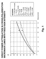
- For radio systems in the bands above 10 GHz, the rain is the main limiting factor for the performance of the line-of-sight radio link. The rain is responsible of two impairments: 1) direct attenuation and 2) depolarization of the transmitted signal. If the radio system uses only one type of channel polarization (Horizontal or Vertical), it is named "Alternate Pattern" system" (or "AP" system). In this case the only direct attenuation must be considered. If the radio system uses both Horizontal and Vertical polarizations and the same frequency, in order to double the capacity of the available channel, it is named "Co-Channel" system (or "CC" system'). In the latter case, other than the direct attenuation also an additional attenuation due to the phenomenon of depolarization must be considered, because the signal transmitted on each of the two orthogonal polarizations interferes with the other one. Since the present invention deals with CC Systems, both phenomena must be considered. For planning purposes, propagation models must be used. The propagation models described in the following ITU-R P 530 standard: "Propagation Data and Prediction Methods Required for the Design of Terrestrial standard Line-Of-Sight Systems" are usually recommended. In accordance with the aforementioned document, when the radio frequency band fall above 10 GHz the overall performance due to the radio propagation is governed from rain. Since the rain is a phenomenon variable both in space and in time, it is necessary to make use of statistic distributions to foresee direct attenuation and depolarization. For example, we can evaluate the 'specific attenuation' γ due to rain exceeded for 0.01 % of all the time (equivalent to 50 min/year) starting from this formula:
- R is the intensity of the precipitation expressed as mm/h exceeded for 0.01 % of time in the worst month of the year, and it is defined for all locations of the globe in the following Rec. ITU-R P 837 standard: "Characteristics of precipitation for propagation modelling"; and
- K and α are coefficients which depend on the frequency and on horizontal H and vertical V polarizations; they are tabulated in the following Rec. ITU-R P 838 standard: "Specific Attenuation Model for rain for use in prediction methods".
- From (Eq.1) the total direct attenuations exceeded for the 0.01% of the time, and for a given link of length L [km], is calculated as:
- This formula is indicated in the Rec. ITU R P 530 to calculate the direct attenuation exceeded for a percent of time p different from 0.01%:
- Radio Frequency = 18 GHz;
- R0.01%= 42 mm/h (corresponding to the mean value for
- Italy in the Rain zone K).
- As can be seen in fig.1 the attenuation for the H polarization is higher than that for V polarization.
- Like the attenuation, also the depolarization has to be characterised by statistical distributions. The parameter that characterizes the phenomenon of the depolarization is named XPD. It is defined as the ratio, after the depolarizing mechanism, between the co-polar signal received, and the cross-polar signal received in the orthogonal polarization. But the rain is not the only mechanism that causes the depolarization, also the transmitter and receiver antennas must be considered. The transmitter antenna, for example, introduces a depolarization XPDTX; this means that if the power wv is transmitted using the V polarization (in the following 'lowercase' symbol w indicates power in linear unit, while 'Uppercase' indicates dB unit), a part wH of this power will fall in the orthogonal polarization, and:
- A similar attenuation XPDRX exists for the receiving antenna.
- The recommended propagation model in ITU-R P 530 states that the rain depolarization XPDRain may be evaluated starting from direct attenuation, with this formula:where wRX(H → H) is the power transmitted on the H polarization and received on H, and so on for the other terms. The following (Eq.7) is a detailed development of the (Eq.6) in logarithmic form:
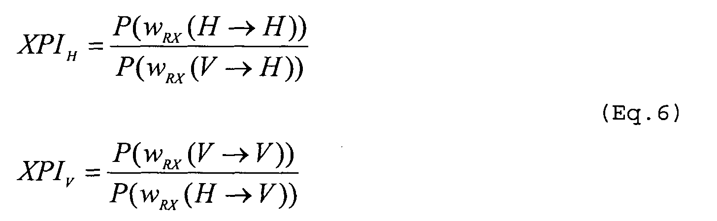 where the parameters have the following meaning:
- PTXV = Power transmitted on the Vertical polarization;
- PTXH = Power transmitted on the Horizontal polarization;
- XPDRain V - XPD due to the rain (see Eq.5);
- XPDRain H = XPD due to the rain (see Eq.5);
- XPDTX = XDP of the transmission antenna;
- XPDRX = XDP of the receiver antenna;
- ARainV = Attenuation due to rain for the Vertical polarization (see also fig.1);
- ARainH = Attenuation due to rain for the Horizontal polarization (see also fig.1).
- In fig.2 the two curves of XPIH and XPIV exceeded for the 0.01% of the time versus the distance D [km] are shown, with these parameters:
- Radio Frequency = 18 GHz;
- R0.01% = 42 mm/h;
- XPDTX = 33 dB;
- XPDRX = 33 dB;
- PTXH = 18 dBm;
- PTXV = 18 dBm.
- As it can be seen in fig.2 the curve of XPIH is always below the curve of XPIV and the difference increases with the increasing of the distance much more than the difference due to the direct attenuation of fig .1. This means that during the rain phenomenon the H polarization suffers not only a bigger direct attenuation than the V one but also a bigger cross-polar interference. To plan a radio link using a cross-polar cochannel system, it is necessary to make a balance between the 'Fading Margin' (FM) and a 'Required Margin for Rain' (RM). The 'Fading Margin' is defined as:
- To define the 'Required Margin for Rain' it is necessary to take into account both direct attenuation and depolarization; the latter causes an interference coming from the orthogonal polarization that degrades the power threshold at the receiver. The 'Required Margin for Rain' may be defined as:where ARainH/V are the attenuations due to rain (see also Eq.3), and (S/N)th is the Signal to Noise ratio at the BER corresponding to the receiver threshold. Note that the 'Required Margin for Rain' must be intended as the 'Required Margin' calculated for a given probability (for example the 0.01% of the overall time). If a more rainy region or/and a lower probability is considered, the 'Required Margin' will increase.

- In fig.3 an example of margin balance is shown. The 'Fading Margin' and the 'Required Margin for Rain' versus distance D [km] have been calculated, assuming the parameters indicated in the LEGENDA, typical for radio system with 32TCM (Trellis Code Modulation) format.
- with reference to fig. 3, when a curve of the RM intersects the curve of FM the maximum length with the relevant polarization is reached. The distances of 10.67 km for H polarization and 21.04 km for V polarization are respectively indicated in the figure. The maximum possible length for the cochannel radio link must be calculated as the minimum between the distances obtained with the two polarizations, so that 10.67 km is the maximum distance for the radio link. The impairment introduced by the reduction of the XPI parameter due to the interference coming from the orthogonal polarization during the rain is evident. As a known countermeasure an XPIC device (Cross Polar Interference Canceller) is usually employed in CC Systems. The international standard IEC 60835-2-11, 1996, Part 2: "Measurement on terrestrial radio-relay systems", Section 11, describes the architecture of a Cross-polarization interference canceller (XPIC) and its impact on the performances of the system.
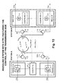
- In fig.4 the main block diagram of a CC System with XPIC is illustrated. With reference to fig.4 two stations indicated as STATION-A and STATION-B connected by cross-polar cochannel FDD (Frequency Division Duplexing) radio link are depicted. The first STATION-A transmits on frequency f1 and receives on frequency f2, while the second STATION-B transmits on frequency f2 and receives on frequency f1. A single antenna with orthogonal feeders is used by each station. The two feeders are connected to respective circulators. These three-port devices are able to keep the transmission and reception signal each other separated at the two ports other the one connected to the common feeder. The two stations A and B include a first transmission-and-reception section connected to the H-circulator and a second transmission-and-reception section connected to the V-circulator. Each H/V section includes a transmitter and a receiver. Concerning STATION-A, the H-section comprises a receiver REC-H-A, equipped with a XPIC device, and a transmitter TRANS-H-A; the V-section comprises a receiver REC-V-A, equipped with a XPIC device, and a transmitter TRANS-V-A. Concerning STATION-B: the H-section comprises a receiver REC-H-B, equipped with a XPIC device, and a transmitter TRANS-H-B; the V-section comprises a receiver REC-V-B, equipped with a XPIC device, and a transmitter TRANS-V-B. Inside the two stations A and B the couple of transmitters are synchronised by a signal OLTX, and the couple of receivers by a signal OLRX, both acting on the respective local oscillators. With D1a and D2a are indicated the baseband transmission signals of STATION-A, respectively horizontally or vertically polarized. Similarly, D1b and D2b indicate the baseband transmission signals of STATION-B, respectively horizontally or vertically polarized. The signals D1a, D2a and D1b, D2b are the ones further indicated as reception signals of the destination stations B and A, respectively. For the aim of describing the connection of the XPIC devices, the structure of the receivers are detailed with reference to the only STATION-B. The block diagram of STATION-B shows the detail of the two receivers REC-H-B and REC-V-B, including a front-end section FRT-H and FRT-V followed by a respective demodulator DEMOD-H and DEMOD-V. Each front-end FRT-H and FRT-V includes a Local Oscillator (LO) for the RF/IF conversion. The two local oscillators are controlled by the synchronisation signal OLRX outputted by a carrier recovery circuit of the PLL (Phase-Locked Loop) type (not shown) driven by the RX input data. The description of the two receivers is similar, so that the only REC-H-B is considered. The demodulator DEMOD-H includes two IF/BB frequency conversion stages, a first one is connected to the front-end FRT-H and a second one is connected to the front-end FRT-V. The two IF/BB stages receive the two intermediate frequency signals, either the IF on the direct H path or the IFX coming from the orthogonal V path, and convert them to baseband BB for the successive processing. An unique VCO (Voltage Controlled Oscillator) is used for the baseband conversion. The VCO is controlled by a symbol synchronisation recovery circuit, not shown in fig.4 so as the A/D and D/A converters. The IF output of the direct IF/BB stage is connected to a first input of a digital adder. The IFx output of the transversal IF/BB stage is connected to the input of an XPIC device, which provides a correction signal (-) at the second input of the digital adder. The output signal of the digital adder reaches the input of a block ATDE (Adaptive Time Delay Equaliser) which outputs a time equalised and cross-polar interference-corrected signal D1a. The operation of the XPIC device is controlled in a known manner by a block CTRL that receives both the orthogonally polarized signal D1a and D2a present at the output of STATION-B. Let T the symbol time, the XPIC device is, for example, a T/2 spaced adaptive FIR filter that estimates the cross-polar interference for the aim of subtracting it from the useful signal.
- For CC Systems equipped with XPIC devices, like the system represented in fig.4, it is possible to define a cross-polar Improvement Factor (XIF) as the XPI difference between the performance with and without the XPIC at specified BER and S/N. When XPIC device is equipped, an increment of XPI is an improvement that can be evaluated with:To see an example let's take the link considered in fig.3 but with a CC system equipped with XPIC devices, assuming the value of XIF = 20 dB. The resulting improvement on the balance between the fading margin FM and the required margin for rain RM is shown in fig.5, where the improvement introduced by the XPIC device is evident at glance. In fact the length of the link has been increased from 10.67 to 16.47 km. Since the XPIH values are low (see fig.2), the H polarization takes more advantage of the XPIC device that mitigates the interference from the orthogonal polarization.

- The XPIC device is the ideal countermeasure against the interference from orthogonal polarization. It is the only one possible when the modulation format employed in the CC system is more complex, for example, than 32TCM; because in this case the system is too sensible to the interference from the orthogonal polarization. To explain this point consider that, in general, an interfering signal, characterized by a given value of C/I [dB], causes a degradation DEG [dB] of the receiver threshold expressed by:Usually a degradation lower than 1 dB can be tolerated. From (Eq.11) supposing DEG = 1 dB, it results that C/I can be at the most 7 dB over the (S/N)th to tolerate the impairments. It follows that to avoid impairments the value of C/I [dB] must satisfy this inequality:


- In a radio link employing a CC-System, and antennas characterized by XPD values: XPDTX and XPDRX, for each channel (V and H), the value of C/I [dB] is given by:
- We need to emphasize that the main requirements for a cochannel system equipped with XPIC devices are:
- in the receiver it is necessary to synchronise the Local Oscillator (some systems synchronise also the transmitter section);
- to feed the XPIC devices, it is necessary to design two additional IFx sections on the orthogonal paths and connect them to the demodulator units. Each IFx section shall include sub-units like: base band frequency converter, A/D converter, and an XPIC section based on adaptive T/2 spaced traversal filter used to drive the orthogonal signal for cancelling the cross-polar interference. These sub-units weigh on price, space, and electrical consumption also when the functionality is not used. Furthermore if the reception/transmission unit is outdoor, the connection for Local Oscillator synchronisation will be consistent.
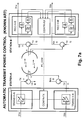
- The cochannel system of fig.4 is usually completed with the embodiment of an Automatic Transmission Power Control (ATPC), as the one depicted in fig.6a. With reference to fig.6a, the two independent loops to control the pair of relevant transmitters are shown for the only STATION-A. Each of the two transmitters TRANS-H-A and TRANS-V-A includes a variable RF power amplifier and a gain control circuit. The two gain control circuits are respectively indicated as CONTR-H-A and CONTR-V-A, respectively. They act upon the reception of respective power control signals PC_COM_H_A and PC_COM_V_A coming from dual control circuits CONTR-H-B and CONTR-V-B belonging to the corresponding receivers REC-H-B and REC-V-B inside STATION-B. The transmission of PC_COM_H_A and PC_COM_V_A signals can advantageously avail of two feedback radio channels. An envelope detector diode inside the two receivers REC-H-A and REC-V-A inside STATION-B is used to sense the attenuation of the reception signal RX on the respective H and V paths. The information about the attenuation is transferred to the control circuits CONTR-H-B and CONTR-V-B. These circuits calculate the incremental power steps, either positive or negative, and generate two power control commands PC_COM_H_A and PC_COM_V_A for the two transmitters TRANS-H-A and TRANS-V-A inside STATION-A. The two power control commands PC_COM_H_A and PC_COM_V_A are translated by the two circuits CONTR-H-A and CONTR-V-A into gain control voltages for the AGCs (Automatic Gain Control) of the two RF transmission power amplifiers.
- In operation, the ATPC functionality of fig.6a automatically controls in a closed-loop scheme the transmission power on the relevant H/V channel in order to counteract all the causes of attenuation typical of a line-of-sight radio link, for example, rain and multipath. A fast closed-loop power control is needed to compensate selective multipath fading, while the rain fading is a slower phenomenon prevalent over 10 GHz. The present invention is only involved with rain fading. The ATPC functionality allows for the same availability obtained by transmitting the maximum power but, at the same time, limiting the transmission power during Clear air conditions thus reducing the produced interference to other links and saving power. The cochannel system of fig.6a, and more in general all the radio systems equipped with the ATPC, in clear air condition usually transmit at the minimum power PMIN, because the power received is strong enough. When there is a fading condition and the received power drops below a given threshold (PTH ATPC), the ATPC loop instructs via the power control commands the relevant transmitter to increase the transmitted power in order to keep the received power as constant as possible and close to the given threshold (PTH ATPC).
- With reference to fig.6b, the two transmission powers can be increased as far as they separately reach the maximum power PMAX. The difference: (PMAX - PMIN) is the 'ATPC Range'. During a rain fading the power received on the H polarisation, is lower than that received on the V polarisation, and decreases more rapidly as the rain increases. So, increasing the rain, the result of the two independent ATPCs is that the power of the H transmitter is increased faster than the power of the V transmitter. This behaviour is highlighted by different slopes of the H/V curves. So we have to take into account that the ATPC introduces automatically a positive difference ΔPATPC between the transmission powers PTXH and PTXV in order to optimally handles Clear air and initial rain conditions. Nevertheless, when the rain intensity increases over the ATPC saturation point for the H signal, the two polarizations are no more optimally handled for that given length of the link. The reason is mainly due to the side effect of the cross-polar interferences of the V channel on the H channel, which besides to be the most penalised one, is no more power increased by the ATPC beyond the saturation.
- Although limited to counteract the only Rayleigh fading and not raining, US 5,392,459 (in the name of NEC Corporation) discloses a "POWER CONTROL IN MICROWAVE TRANSMISSION SYSTEM INCREASING POWER OF BOTH HORIZONTALLY AND VERTICALLY POLARIZED WAVES" which could be erroneously confused, at first sight, with the matter of the invention described later on. Fig.7a (reproduced) shows the ATPC control system of the cited invention applied to an XPIC system like the one of fig.4. By comparison with the prior art of fig.6a, it can be noticed that an unique ATPC control is adopted in the system of fig.7a, instead of the independent twos for the two orthogonal channels. This is perfectly in line with the subject-matter of the NEC's invention where: "The transmit powers of the polarized waves of the object frequency channel are simultaneously increased of the same entity when a drop of the receive signal level of at least one of the two polarized waves of the object frequency channel is detected". The aim is that of preventing the cross-polar interference otherwise due to the increase of only one polarized signal. With reference to fig.7a, the STATION-A includes an unique power control block CONTR-TX connected to the two variable RF power amplifiers of the two transmitters TRANS-H-A and TRANS-V-A. The CONTR-TX block receives a power control command PC_COM from a CONTR-RX power control block included in STATION-B. Each of the two receivers REC-H-B and REC-V-B includes: "a first level detector (the upper diode) for detecting the reception intensity of a microwave of the object frequency channel, and a second level detector (the lower diode preceded by a notch filter which stops the signal of the object frequency channel) for detecting the reception intensity of another frequency channel adjacent to the object frequency channel. All the level detectors forward their power measures to the common CONTR-RX block".
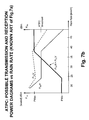
- The successive fig.7b attempts to illustrate the behaviour of the power control system of fig.7a, in particular of the CONTR-RX block. As the power control system of fig.7a is fast enough for counteracting the Rayleigh fading, it also can be responsive for counteracting the rain fading if the case it needed. With reference to fig.7b, in case the rain attenuation drives under threshold the most penalized channel H, the two transmission powers PTXH and PTXV (logarithmic) are equally increased of a ΔP linearly increasing with the rain rate. A corresponding ΔP consequently appears between the reception powers PRXV and PRXH during all the power control range and remains in the saturation region. The ΔP gap on the reception power is enough to consider non optimal the handling of rain attenuation, either inside or outside the control range. The equal increase of H and V transmission powers for preventing cross-polar interferences due to Rayleigh fading generates as a consequence an overpower of the V channel other than the one strictly needed to counteract the rain fading. Besides the fact that overpower is costly, the major drawback is a considerable decreasing of the Cross Polar Isolation (XPI) and a worsening of the performance of the link with the rain attenuation.
- From numerical results, coming from the propagation model described by the Rec. ITU-R P 530, it is evident that the polarization H is more disadvantaged than polarization V. This can be seen both in terms of attenuation (see fig.1), and in terms of interference of one polarization over the other (see fig.2). Since the overall performance of the link with a CC System is governed from the worst-case between the two polarizations, it results that the whole system performance undergoes the penalty on the H channel, also if the other polarization works well (see the margin balance of fig.3). As the direct attenuation is concerned, the H polarization will be always disadvantaged also in the presence of the XPIC device but, as the interference from orthogonal polarization is concerned, if the modulation format is not too complex (for example 32TCM or less) and the radio frequency band fall into the range for which the overall performance due to the radio propagation is governed from rain (above 10 GHz), it is possible to look for an alternative more convenient than XPIC device and without the drawbacks of the method disclosed in the NEC's patent. Furthermore, for more complex modulation formats less cumbersome XPIC devices are preferable or in alternative best performances with the same XPIC.
- The main object of the present invention is that to overcome the aforementioned drawbacks of the known art due to the rain attenuation and indicate an optimal transmission power setting method and system for a line-of-sight radio link employing cross-polarized cochannel signals.
- Further object of the invention is that to dynamically control the optimal power setting in a closed-loop ATPC.
- To achieve said objects, a transmission power setting method for a line-of-sight radio link employing cross-polarized cochannel signals is claimed, as disclosed in the relevant method claims.
- Is also claimed a transmission power setting system in a cross-polarization cochannel line-of-sight radio link operating in accordance with said method, as disclosed in the relevant system claims.
- The original idea is to improve the performance of the radio link by introducing an optimum positive difference ΔP = PTXH - PTXV, expressed in dB, between the power used on the H channel and that used on the V channel. This operation permits mainly to improve the XPIH of the factor ΔP [dB] (see Eq.7), which is the parameter that measures the interference from orthogonal polarization (see fig.2). Of course the XPIv will be consequently reduced of the same factor ΔP [dB], but for this parameter there is enough margin to do it. Consider as an example the balance between FM and RM shown in fig.8, where a value of ΔP = 3 dB has been used. As it can be seen comparing the results with those of fig.3, an increase of the overall length of the hop is obtained, passing from 10.67 to 13.37 km, so obtaining an improvement of near the 30%. Note that the distance resulting for the V polarization is 18.05 km, and so there is still margin to further improve the limit for ΔP, of course until to equal distance on both polarizations is reached. This means that given a fixed target for the performance in terms of unavailability of the hop (usually a value given is the 0.01% of the time corresponds to an unavailability lesser than 50 min/year), it is possible to planning a radio link over a longer distance. The question is faceable from another point of view: given the distance of the link, it is possible reducing the unavailability [min/year] of the link by the introduction of a ΔP between the powers on two polarizations. Of course for each situation there will be an optimum ΔP that permits of improve the performance of the H polarization without too penalizing the V. This optimum ΔP will depend on all the parameters involved in the link, and has to be evaluated for each situation.
- Without ΔP the unavailability of the H channel is bigger than that of the V channel. If a ΔP > 0 is introduced between the H and V channels, the first unavailability reduces and the other increases, so that for a given ΔP the H and V channels will have equal unavailability. This ΔP value can be defined as "optimum ΔP": that is, for a given length of the link the optimum ΔP is the one for which the same unavailability exists for H and V polarizations. A relevant example of a margin Balance between FM and RM on a 18 km radio link with an optimum ΔP = 5.8 dB is shown in fig.9 (the other parameters of radio system and antennas are the ones of the preceding fig.8). With a ΔPOPT of 5.8 dB there is an unavailability of 0.0144% (corresponding to 76 min/year) for both H and V polarization and a maximum distance DMAX = 18 km, which is the same for the two H and V channels as it results from the FM and RM balance.
- The optimum ΔP can be kept constant for all the transmission time (whether in 'clear air' or during rain conditions) or varied dynamically according to an embodiment of the invention addressed to radio systems with ATPC. The ATPC can be embodied for featuring the power setting either on the transmission or the reception side, indifferently. Diversely from the conventional ATPC systems, which saturate the transmission powers of both the orthogonal polarizations for large increasing of the rain intensity (see fig.6b), the ATPC of the present invention holds the optimum ΔP inside the power control saturation range of the horizontally polarized signal. (see fig.14 and fig.16). This allow to keep the power levels of both H and V reception signals closer to each other even inside the saturation range of the ATPC, as required for an optimal handling of the rain attenuation able to provide satisfactory performance of the link. The ATPC of the present invention strongly differs from the ones disclosed in the NEC' s patent in which a ΔP between the H and V transmission powers is not implemented, so that an unfit ΔP appears between the reception signals.
- The features of the present invention which are considered to be novel are set forth with particularity in the appended claims. The invention, together with further objects and advantages thereof, may be understood with reference to the following detailed description of an embodiment thereof taken in conjunction with the accompanying drawings given for purely non-limiting explanatory purposes and wherein:
- fig.1, already described, shows two H and V attenuation curves with fixed rain intensity;
- fig.2, already described, shows two H and V cross-polar isolation (XPI) curves with fixed rain intensity and given cross-polar depolarization XPDTX and XPDRX;
- fig.3, already described, shows the curves of fading margin (FM) and required margin for rain (RM) for H and V polarizations, adopting a given set of system parameters and without XPIC device;
- fig.4, already described, shows a cochannel cross-polarization transmission system of the prior art equipped with XPIC devices;
- fig.5, already described, shows some FM and RM curves which illustrate the balance improvement due to the XPIC device with respect to the balance of fig.3;
- fig.6a, already described, shows the circuital architecture of a conventional ATPC system the transmission system of fig.4 is equipped with;
- fig.6b, already described, shows the transmission and reception power diagrams vs. rain rate of the ATPC system of fig.6a;
- fig.7a, already described, shows the circuital architecture of an ATPC system in accordance with a cited US patent;
- fig.7b, already described, shows the possible transmission and reception power diagrams vs. rain rate of the ATPC system of fig.7a;
- fig.8, already described, shows some FM and RM curves in accordance with the present invention which illustrate the balance improvement due to a fixed 3 dB ΔP between H and V transmission powers with respect to the balance of fig.3;
- fig.9, already described, differs from the preceding fig.8 for a further improvement of the balance due to the optimal value of ΔP;
- fig.10 shows a circuital implementation for setting an optimum ΔP in a static manner in accordance with a preferred embodiment of the present invention;
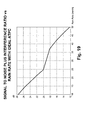
- fig.11 shows some curves illustrating the optimum static ΔP and the consequent link unavailability vs. distance between the antennas;
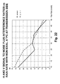
- fig.12 shows the curves of signal to noise plus interference ratio vs. rain rate of V and H polarizations obtainable with the circuital implementation of fig.10;
- fig.13 shows a circuital implementation according to a first variant of the invention for ATPC featuring the control at the transmission side;
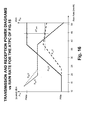
- fig.14 shows the transmission and reception power diagrams vs. rain rate obtainable with the circuital implementation of the preceding fig.13;
- fig.15 shows a circuital implementation according to a second variant of the invention for ATPC featuring the control at the reception side;
- fig.16 shows the transmission and reception power diagrams vs. rain rate obtainable with the circuital implementation of the preceding fig.15;
- fig.17 shows the curves of V and H reception powers vs. rain rate with ideal ATPC;
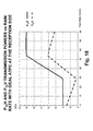
- fig.18 shows the curves of V and H transmission powers vs. rain rate with ideal ATPC at the reception side;
- fig.19 shows the curves of signal to noise plus interference ratio vs. rain rate of V and H polarizations with ideal ATPC;
- fig.20 shows the curves of V and H transmission powers vs. rain rate with non ideal ATPC at the transmission side (plus ideal by comparison);
- fig.21 shows the curves of V and H reception powers vs. rain rate with non ideal ATPC at the transmission side; and
- fig.22 shows the curves of signal to noise plus interference ratio vs. rain rate of V and H polarizations with non ideal ATPC at the transmission side.
- It is appropriate to distinguish two kinds of radio systems, according to the fact that they use, or not, the ATPC (Automatic Transmission Power Control). In fig.10 a 'static' (without ATPC) power setting system in accordance with a preferred embodiment of the invention is depicted. The power setting system of fig.10 gives the best possible performance in terms of unavailability to a cochannel system without XPIC, although the use of the XPIC for high level modulations is possible and further improves the overall performances.
- With reference to fig.10, a partial representation of STATION-A (fig.4) including the two TRANS-H-A and TRANS-V-A transmitters and a functional block named CONTROL LOGIC is shown. The two transmitters include a variable-gain RF power amplifier and an envelope detector diode D-H and D-V, according to the H, V notation, for detecting the level of the relevant transmission signal. The control logic block receives an optimum ΔP value (expressed in dB) together with the voltages representing the two envelopes detected on the H and V channels, and calculates two control signals for regulating the gain of the two RF power amplifiers in order Lo keep constant, and equal to the optimum ΔP, the difference between the transmission powers (expressed in dB) on the H and V channels.
- In operation, the optimum 'static' ΔP is calculated in advance (off-line) during the planning of the link, and successively kept constant for all the transmission time. The limitation to the optimum ΔP value stated in Eq.16 takes into account rain and 'clear air' conditions. In order to determine the law for the optimum 'static' ΔP it is necessary to consider that in conditions of 'clear air' the value assigned to ΔP cannot be too large, otherwise the interference of the H channel on the V should become too strong. As previously said, the power on the V channel must be ΔP dB always lower than that on the H channel, with that the XPIV on the V channel (defined as the C/I when the interfering signal is that on the H channel) is reduced consequently. Then from (Eq.12) the following inequality is valid:where XPDTOT ANT is the total XPD due to the two antennas (transmitter and receiver), and corresponds to the XPI for both polarisations, in conditions of 'clear air'. Therefore, the following maximum value for ΔP can be defined as a function of the two antenna characteristics and of the receiver threshold:
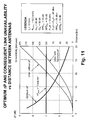
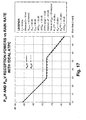
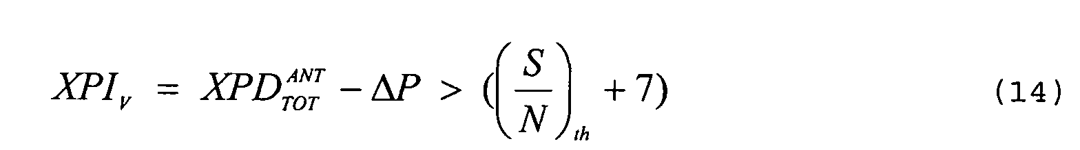 It is clear that, if antennas with a better XPD are used, the ΔPMAX will increase consequently. After having defined the ΔPOPT and the ΔPMAX in 'clear air' condition, and for given parameters of the two antennas and the system, a curve of ΔPOPT versus distance D [km] can be calculated; the result is shown in fig.11, obtained with the parameters indicated in the LEGENDA. With reference to fig.11 the following curves are reported:
- ΔPOPT versus distance D [km] ;
- ΔPMAX for 'clear air conditions' = 7 dB (as it results from XPD values of the antennas, and from the receiver threshold);
- unavailability versus distance D [km], without any ΔP between the transmission powers;
- unavailability versus distance D [km], with the optimum ΔP (ΔPOPT) .
- As shown in fig.11, assuming distances lower than 7.5 [km], ΔPOPT is higher than ΔPMAX, otherwise it is lower. This is not the rule; it depends from the data assumed for the radio link. For example if we consider a more rainy zone (with Rain Rate higher than 42 mm/h) the values of ΔPOPT will increase. In general, three cases are possible:
- 1. The curve of ΔPOPT versus D is always below ΔPMAX.
- 2. The curve of ΔPOPT versus D is always above ΔPMAX.
- 3. The curve of ΔPOPT versus D intersects ΔPMAX at only a certain value. On the bases of the possible cases, we can define a curve for representing ΔPNO-ATPC =ΔP' in the following way:
-
- After having calculated the ΔPOPT versus distance D [km] , we know that on average, for that geographic zone, the value of ΔPOPT so introduced, permits to optimise the time of outage on the two polarisations. However, the manner to use this value depends from the radio system we are considering.
- Once ΔPOPT is set by the circuitry of fig.10, the ratio s/(n+i) versus rain rate can be evaluated for the two polarisations. As an example consider the curves in fig.12 calculated using the parameters indicated in the LEGENDA. The vale of ΔPOPT = 6.6 dB results from the optimisation over a distance D = 10 km (see fig.11). Note that an unavailability of 20 min/y corresponds to the ΔPOPT, and this value is used to calculate the direct attenuations and depolarizations due to rain. Note also that the two curves of fig.12 intersect only for Rain Rate = 42 mm/h, which is the value of the rain rate corresponding to the target unavailability point in the link budget; and the corresponding s/(n+i) ratio is 16 dB, which is the BER threshold for the radio system. This suggests a way to calculate ΔPOPT based on equating the s/(n+i) ratio of both the cross-polarized reception signals with the target parameters.
- Another preferred embodiment of the invention covers systems with ATPC; the aims of this functionality has been described in the introduction. Then, to fully exploit the advantages of the optimum ΔP even in ATPC systems, the parameters of the ATPC shall be set in the manner to obtain the following behaviour for a given distance:
- in clear air the two channels have the same (minimum) power;
- at maximum fading, we would like the ATPC to bring the
system into the same optimal conditions of a system without
ATPC and therefore it shall bound to ΔPOPT (ΔPMAX was only
used in systems without ATPC to cope with clear air
interference and therefore shall not be applied to ATPC
systems). The following equation applies, where ΔPOPT is the
value calculated as above (see fig.11) for a given
distance, rain zone, and system gain parameters.
- This can be done in several ways. The most straightforward approach is to bound the maximum transmitted power of the V channel in the ATPC system to be ΔPOPT below the power of the H channel (thus preventing V channel to increase its power up to the maximum). Another way is to act in the receiver to control the received power of H and V channels to be the same. This second approach gives slightly different results but the performances are very similar. The most straightforward approach correspond to a first variant of the invention embodied for ATPC, as shown in fig.13, while the second approach corresponds to a second variant shown in fig.15.
- With reference to fig.13 (first variant), a partial representation of STATION-A and STATION-B of fig.4 is shown. The partial representation of STATION-A includes the two transmitters TRANS-H-A and TRANS-V-A and a sole control block named CONTR-TX. The two transmitters each includes a variable-gain RF power amplifier. The partial representation of STATION-B includes the two receivers REC-H-B and REC-V-B, each of them includes an envelope detector diode followed by a control block. The two diodes are labelled D-H and D-V, and the control blocks are named CONTR-RX-H and CONTR-RX-V (in accordance with the H, V notation), the latter generate two respective commands PW-COM-H and PW-COM-V which include the corrections sent to the CONTR-TX block inside STATION-A (via two feedback radio cannels) for controlling the power level of the H and V transmission signals. The two commands PW-COM-H and PW-COM-V are generated independently with each other, as in conventional ATPC, by comparing the detected envelopes with the ATPC threshold. The control block CONTR-TX receives the two commands PW-COM-H and PW-COM-V and the optimum value ΔPOPT (calculated in advance), filters the received corrections, and generates two control signals for regulating the AGCs of the two RF power amplifiers, in order to operate as the PTXH and PTXV curves versus rain rate indicated in fig.14.
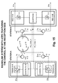
- With reference to fig.15 (second variant), a partial representation of STATION-A and STATION-B of fig.4 is shown. The partial representation of STATION-A includes the two TRANS-H-A and TRANS-V-A transmitters. The two transmitters include a variable-gain RF power amplifier and a and a control block. The two control blocks are named CONTR-TX-H and CONTR-TX-V, accordingly. The partial representation of STATION-B includes the two receivers REC-H-B and REC-V-B and a sole control block named CONTR-RX. The two receivers each includes an envelope detector diode for sensing the power level of the reception signal. The two diodes are labelled D-H and D-V (in accordance with the H, V notation). The detected envelopes are sent to the control block CONTR-RX, that calculates in correspondence two power control commands PC_COM_H and PC_COM_V directed (via two feedback radio channels) to the control blocks CONTR-TX-H and CONTR-TX-V, respectively. The control block CONTR-RX calculates instant by instant the difference ΔP between each detected envelope. The differences are filtered and translated into power control commands PC_COM_H and PC_COM_V suitable for equating the reception powers on the H and V channels, as indicated by the PRXH and PRXV curves versus rain rate of fig.16. The two blocks CONTR-TX-H and CONTR-TX-V act on the AGCs of the two RF power amplifiers in accordance with the received power control commands, in order to obtain the PTXH and PTXV curves versus rain rate indicated in fig.16. It is of course possible, though probably useless, to distribute the filtering function between transmitter and receiver.
- The description continues with some arguments on an 'Ideal ATPC' developed for a better understanding of the two ATPC variants really implemented; the successive figures support these arguments.
- Given a radio link of length D [km] and a rain rate R [mm/h], and not considering the limitation imposed by ΔPMAX with the clear air condition, the value ΔPOPT is such that if it is applied to the transmitted powers, so that: PTXH = PTXV + ΔPOPT, then the two signals transmitted on the two polarisations reach the BER threshold with the same probability of unavailability U [%]. Therefore, the first request for the ATPC mechanism could be that when the radio link reaches the BER threshold for that given rain rate R (function of rain zone and target unavailability), then the difference between the transmitted powers would be exactly ΔPOPT. Nevertheless, we have to consider also the behaviour of the ATPC when the intensity of the rain is increasing from 0 to R. To do this, we can define 'Ideal ATPC' the one which, for each value of rain rate from 0 to R, optimised the s/(n+i) by making equals the two ratios:where:

- This condition equalizes (and optimises) the performance of the H and V channels, instant by instant, during the rain fading process; when the rain rate reaches the target value R, the two ratios are equals and are the (S/N)th [dB]. It's known that the H direct attenuation is higher than that of the V (see fig.1), so to describe the behaviour of the 'ideal ATPC' it is firstly assumed that a standard ATPC works to control the power received on the H polarization, with these parameters: Pth ATPC = -72 dBm; PTMAX ATPC = 18 dBm. Then the ideal received power for the V polarization has been calculated following (Eq.18). As it can be seen in fig.17, with the parameters indicated in the LEGENDA, the two received powers PRXH and PRXV are very close to each other for all the values of the rain rate (the maximum difference can be evaluated as less than 0.5 dB). This also implicates equal interference conditions on the two H and V channels. In fig.18 the two transmission powers PTXH and PTXV versus rain rate for the ideal ATPC, which have been calculated starting from the detected reception powers, are shown. Please note that the ideal condition would require that PMIN of V channel be lower than 8 dBm, thus requesting an ATPC range, larger than the actual one. In fig.19 the s/(n+i) ratio versus rain rate corresponding to ideal ATPC is shown; the ratio is the same for the two polarizations, of course.
- A possible schema very close to 'ideal ATPC' is the one of the second variant shown in fig.15. The only exception between fig.18 and 16, as far as PTXH and PTXV curves are concerned, is represented by the minimum transmission power PMIN. In the real implementation of the two variants there is a minimum power PMIN = 8 dBm (so as a maximum transmission power PMAX = 18 dBm) and the V channel would never go below PMIN. The deviation from ideality visible in fig.15 is not relevant, because it occurs in low rain fading area where the s/(n+i) ratio is far from threshold, so that the non ideal behaviour has no consequences on the performance. Apart from this, the behaviour of the circuital embodiment of fig.15 is very close to the ideal at rain rates above 30 mm/h.
- Another possible implementation is the one of the first variant shown in fig.13. The control block CONTR-TX operates on the H channel as usual and saturates the V channel at a maximum power ΔPOPT [dB] below the maximum power PMAX of the H channel. Therefore a non ideal behaviour is introduced as shown in fig.20 at rain rates above 35 mm/h. There is always the non ideal behaviour due to PMIN, as in the second variant, which is not particularly important in this context. The specified behaviour of the real transmission power PTXV is therefore defined as follows with respect to ideal behaviour:
- PTXV ideal < PMIN: PTXV = P min;
- PMIN < PTXV ideal < PTXH MAX - ΔPOPT: PTXV = PTXV ideal;
- ideal > PTXH MAX - ΔPOPT: PTXV = PTXH MAX - ΔPOPT.
- In fig.21 the curves of the reception powers PRXV and PRXH versus rain rate relevant to the first variant are reported. In fig.22 the curves of the H and V s/(n+i) ratios versus rain rate relevant to the first variant are reported.
Claims (15)
- A transmission power setting method in a cross-polarization cochannel line-of-sight radio link subjected to rain attenuation, characterised in that: an optimum positive difference value (ΔPOPT)is set between the logarithms of the transmission powers of the horizontally (H) and vertically (V) polarized signals; said optimum difference (ΔPOPT) being calculated in order to have equal probability of unavailability of the link for both cross-polarized signals (H, V), given the length of the link, the rain zone and the corresponding threshold for the signal to noise plus interference ratio.
- The method of the preceding claim, characterised in that said optimum positive difference (ΔPOPT) is limited to be equal to or lower than a maximum difference value (ΔPMAX) calculated for a clear air condition.
- The method of claim 1 or 2, characterised in that said given length of the link is a maximum length (DMAX) calculated by forcing to be equal the balances between the fading margin (FM) and the required margin for raining (RM) versus the length of the link of the horizontally and vertically polarized signals (H, V).
- The method of one of the preceding claims, characterised in that said optimum positive difference value (ΔPOPT) is calculated in advance and hold on for all the transmission time.
- The method of claim 1, characterised in that said optimum positive difference value (ΔPOPT) is set in conjunction with a closed-loop power control acting on both the cross-polarized transmission signals (H, V).
- The method of the preceding claim, characterised in that a minimum transmission power (PMin) compatible with the maximum transmissible power (PMax) and the width of the power control range is set for both the cross-polarized signals (H, V) .
- The method of claim 5 or 6, characterised in that the power level of the vertically polarized transmission signal (PTXV) is kept constant when the summation of it with said optimum positive difference (ΔPOPT) calculated in advance reaches the maximum power (PMAX) permitted to the horizontally polarized transmission signal (PTXH).
- The method of claim 5 or 6, characterised in that said optimum positive difference value (ΔPOPT) is obtained by equating the signal to noise plus interference ratios of the two cross-polarized reception signals (H, V).
- A transmission power setting system in a cross-polarization cochannel line-of-sight radio link subjected to rain attenuation, characterised in that: includes control means (CONTROL LOGIC, CONTR-TX, CONTR-RX-H, CONTR-RX-V, CONTR-RX, CONTR-TX-H, CONTR-TX-V) for setting an optimum positive difference (ΔPOPT) value between the logarithms of the transmission power of the horizontally (H) and vertically (V) polarized signals in order to have equal probability of unavailability of the link for both cross-polarized signals (H, V), given the length of the link, the rain zone, and the corresponding threshold for the signal to noise plus interference ratio.
- The system of the preceding claim, characterised in that said control means (CONTROL LOGIC) are placed in the transmitting station (STATION-A) for receiving the measures of the transmission power levels (PTxH, PTXV) of the horizontally (H) and vertically (V) polarized signals at the output of relevant detecting means (D-H, D-V), and further receiving the value of said optimum positive difference (ΔPOPT) that is calculated in advance, and generating in correspondence two gain control commands directed to the transmitters of the cross-polarized signals (TRANS-H-A, TRANS-V-A) in order to achieve said optimum difference (ΔPOPT) and kept it constant for all the transmission time.
- The system of claim 9, characterised in that said control means (CONTR-TX; CONTR-RX-H, CONTR-RX-V) are subdivided in two parts, a first one (CONTR-RX-H, CONTR-RX-V) placed in the receiving station (STATION-B) and a second one (CONTR-TX) in the transmitting station (STATION-A) in order to perform a closed-loop power control having a given dynamic power range:the first control means (CONTR-RX-H, CONTR-RX-V) being arranged for receiving the measures of the reception power levels (PRXH, PRXV) of the horizontally (H) and vertically (V) polarized signals at the output of relevant detecting means (D-H, D-V) and tracking the differences between each measure and an intervening power threshold, in order to generate relevant corrections (PW-COM-H, PW-COM-V) to the transmission powers;the second control means (CONTR-TX) being arranged for dynamically controlling the power level of the cross-polarized transmission signals (PTXH, PTXV) upon the reception of said corrections (PW-COM-H, PW-COM-V) and said optimum value of the positive difference (ΔPOPT) that is calculated in advance.
- The system of claim 11, characterised in that the second control means (CONTR-TX) being further arranged for holding on the power level of the vertically polarized transmission signal (PTXV) when the summation of it with said optimum value of the positive difference (ΔPOPT) reaches the maximum power (PMAX) permitted to the horizontally polarized transmission signal (PTXH).
- The system of claim 11 or 12, characterised in that said the second control means (CONTR-TX) include filtering means for averaging in time said corrections (PW-COM-H, PW-COM-V).
- The system of claim 9, characterised in that said control means (CONTR-RX, CONTR-TX-H, CONTR-TX-V) are subdivided in two parts ; a first one (CONTR-RX) placed in the receiving station (STATION-B) and a second one (CONTR-TX-H, CONTR-TX-V) in the transmitting station (STATION-A) in order to perform a closed-loop power control having a given dynamic power range:the first control means (CONTR-RX) being arranged for receiving the measures of the reception power levels (PRXH, PRXV) of the horizontally (H) and vertically (V) polarized signals at the output of relevant detecting means (D-H, D-V) and generating respective power control commands (PC-COM-H, PC-COM-V) including relevant corrections to the corresponding transmission powers (PTXH, PTXV) for dynamically equating the reception power levels (PRXH, PRXV);the second control means (CONTR-TX-H, CONTR-TX-V) being arranged for acting on the gain of the two transmitters (TRANS-H-A, TRANS-V-A) of the cross-polarized signals (H, V) accordingly to said power control commands (PC-COM-H, PC-COM-V).
- The system of claim 13, characterised in that said first control means (CONTR-RX) include filtering means for averaging in time said power control commands (PC-COM-H, PC-COM-V).
Priority Applications (4)
| Application Number | Priority Date | Filing Date | Title |
|---|---|---|---|
| EP03425608A EP1517455B1 (en) | 2003-09-18 | 2003-09-18 | Transmission power control method for cross-polarized signals |
| ES03425608T ES2344783T3 (en) | 2003-09-18 | 2003-09-18 | TRANSMISSION POWER CONTROL PROCEDURE FOR ORTOGONAL POLARIZATION SIGNS. |
| DE60333097T DE60333097D1 (en) | 2003-09-18 | 2003-09-18 | Transmission power control method for orthogonally polarized signals |
| AT03425608T ATE472200T1 (en) | 2003-09-18 | 2003-09-18 | TRANSMIT POWER CONTROL METHOD FOR ORTHOGONALLY POLARIZED SIGNALS |
Applications Claiming Priority (1)
| Application Number | Priority Date | Filing Date | Title |
|---|---|---|---|
| EP03425608A EP1517455B1 (en) | 2003-09-18 | 2003-09-18 | Transmission power control method for cross-polarized signals |
Publications (2)
| Publication Number | Publication Date |
|---|---|
| EP1517455A1 true EP1517455A1 (en) | 2005-03-23 |
| EP1517455B1 EP1517455B1 (en) | 2010-06-23 |
Family
ID=34178699
Family Applications (1)
| Application Number | Title | Priority Date | Filing Date |
|---|---|---|---|
| EP03425608A Expired - Lifetime EP1517455B1 (en) | 2003-09-18 | 2003-09-18 | Transmission power control method for cross-polarized signals |
Country Status (4)
| Country | Link |
|---|---|
| EP (1) | EP1517455B1 (en) |
| AT (1) | ATE472200T1 (en) |
| DE (1) | DE60333097D1 (en) |
| ES (1) | ES2344783T3 (en) |
Cited By (4)
| Publication number | Priority date | Publication date | Assignee | Title |
|---|---|---|---|---|
| WO2013091713A1 (en) * | 2011-12-22 | 2013-06-27 | Telefonaktiebolaget L M Ericsson (Publ) | Automatic transmit power control in xpic configuration for wireless applications |
| WO2015024184A1 (en) * | 2013-08-20 | 2015-02-26 | 华为技术有限公司 | Method for controlling transmission power in multichannel system, reception end and transmission end |
| CN112673682A (en) * | 2018-12-20 | 2021-04-16 | Oppo广东移动通信有限公司 | Power distribution method, terminal equipment and storage medium |
| US12512877B1 (en) | 2025-07-02 | 2025-12-30 | Imam Mohammad Ibn Saud Islamic University | System and method for mitigating rain-induced crosstalk in wireless communications |
Citations (1)
| Publication number | Priority date | Publication date | Assignee | Title |
|---|---|---|---|---|
| US5392459A (en) * | 1991-11-27 | 1995-02-21 | Nec Corporation | Power control in microwave transmission system increasing power of both horizontally and vertically polarized waves |
-
2003
- 2003-09-18 AT AT03425608T patent/ATE472200T1/en not_active IP Right Cessation
- 2003-09-18 EP EP03425608A patent/EP1517455B1/en not_active Expired - Lifetime
- 2003-09-18 ES ES03425608T patent/ES2344783T3/en not_active Expired - Lifetime
- 2003-09-18 DE DE60333097T patent/DE60333097D1/en not_active Expired - Lifetime
Patent Citations (1)
| Publication number | Priority date | Publication date | Assignee | Title |
|---|---|---|---|---|
| US5392459A (en) * | 1991-11-27 | 1995-02-21 | Nec Corporation | Power control in microwave transmission system increasing power of both horizontally and vertically polarized waves |
Non-Patent Citations (1)
| Title |
|---|
| KALATIZADEH Y ET AL: "Active atmospheric fade compensation for spacecraft antennas", NINTH INTERNATIONAL CONFERENCE ON ANTENNAS AND PROPAGATION (CONF. PUBL. NO.407), NINTH INTERNATIONAL CONFERENCE ON ANTENNAS AND PROPAGATION (CONF. PUBL. NO.407), EINDHOVEN, NETHERLANDS, 4-7 APRIL 1995, 1995, London, UK, IEE, UK, pages 395 - 399 vol.2, XP002268713, ISBN: 0-85296-637-7 * |
Cited By (8)
| Publication number | Priority date | Publication date | Assignee | Title |
|---|---|---|---|---|
| WO2013091713A1 (en) * | 2011-12-22 | 2013-06-27 | Telefonaktiebolaget L M Ericsson (Publ) | Automatic transmit power control in xpic configuration for wireless applications |
| US20140323174A1 (en) * | 2011-12-22 | 2014-10-30 | Telefonaktiebolaget L M Ericsson (Publ) | Automatic transmit power control in xpic configuration for wireless applications |
| US9432948B2 (en) | 2011-12-22 | 2016-08-30 | Telefonaktiebolaget Lm Ericsson (Publ) | Automatic transmit power control in XPIC configuration for wireless applications |
| WO2015024184A1 (en) * | 2013-08-20 | 2015-02-26 | 华为技术有限公司 | Method for controlling transmission power in multichannel system, reception end and transmission end |
| US9510303B2 (en) | 2013-08-20 | 2016-11-29 | Huawei Technologies Co., Ltd. | Method for controlling transmit power in multichannel system, receive end, and transmit end |
| CN112673682A (en) * | 2018-12-20 | 2021-04-16 | Oppo广东移动通信有限公司 | Power distribution method, terminal equipment and storage medium |
| CN112673682B (en) * | 2018-12-20 | 2023-02-28 | Oppo广东移动通信有限公司 | A power distribution method, terminal equipment and storage medium |
| US12512877B1 (en) | 2025-07-02 | 2025-12-30 | Imam Mohammad Ibn Saud Islamic University | System and method for mitigating rain-induced crosstalk in wireless communications |
Also Published As
| Publication number | Publication date |
|---|---|
| DE60333097D1 (en) | 2010-08-05 |
| ATE472200T1 (en) | 2010-07-15 |
| EP1517455B1 (en) | 2010-06-23 |
| ES2344783T3 (en) | 2010-09-07 |
Similar Documents
| Publication | Publication Date | Title |
|---|---|---|
| US4495648A (en) | Transmitter power control circuit | |
| EP0548939B1 (en) | Transmission power control system capable of keeping signal quality constant in mobile communication network | |
| JP4290212B2 (en) | Antenna adjustment system and method in communication state of mobile station | |
| US7151740B2 (en) | Transmit power control for an OFDM-based wireless communication system | |
| US5566165A (en) | Transmission power control method and a communication system using the same | |
| KR100215947B1 (en) | Transmission power control method and device in CDMA cellular mobile telephone system | |
| AU727141B2 (en) | Method of and apparatus for interference rejection combining and downlink beamforming in a cellular radiocommunications system | |
| US8050702B2 (en) | Mobile station and transmission power control method in mobile station | |
| RU2422995C2 (en) | Reduction of usefull current in circuits with rx diversity | |
| US7920889B2 (en) | Transmitting apparatus, receiving apparatus and transmission power control method | |
| US8755292B2 (en) | Apparatus and method for controlling uplink transmission power in a communication system | |
| WO1998042150A2 (en) | Downlink smart antennas for is-54/is-136 tdma systems | |
| US9432948B2 (en) | Automatic transmit power control in XPIC configuration for wireless applications | |
| EP1517455B1 (en) | Transmission power control method for cross-polarized signals | |
| US10568043B2 (en) | Communication device and communication method | |
| US4769825A (en) | Communications transmission system for electromagnetic waves | |
| US20050163271A1 (en) | Cross polarized wave interference eliminating system and method | |
| CN101022666A (en) | Method for installing adaptive switch point in trunk cooperative transmission network frame structure | |
| Hui et al. | Uplink user power control for low-orbit satellite communication systems | |
| Saghaei et al. | Variable step closed-loop power control in cellular wireless CDMA systems under multipath fading | |
| US20100240409A1 (en) | Wireless communication system, wireless base station, wireless terminal station, and transmission power control method using the same | |
| EP1116343B1 (en) | Apparatus, and associated method, for effectuating power control of a communication device | |
| US7158490B1 (en) | Apparatus, and associated method, for effectuating power control of a communication device | |
| Sampietro et al. | Cochannel systems: optimum link length with polarisation driven power control for systems working at high frequencies and without copolar canceller | |
| Villier et al. | On the application of uplink optimum combining to base station reception |
Legal Events
| Date | Code | Title | Description |
|---|---|---|---|
| PUAI | Public reference made under article 153(3) epc to a published international application that has entered the european phase |
Free format text: ORIGINAL CODE: 0009012 |
|
| AK | Designated contracting states |
Kind code of ref document: A1 Designated state(s): AT BE BG CH CY CZ DE DK EE ES FI FR GB GR HU IE IT LI LU MC NL PT RO SE SI SK TR |
|
| AX | Request for extension of the european patent |
Extension state: AL LT LV MK |
|
| 17P | Request for examination filed |
Effective date: 20050922 |
|
| AKX | Designation fees paid |
Designated state(s): AT BE BG CH CY CZ DE DK EE ES FI FR GB GR HU IE IT LI LU MC NL PT RO SE SI SK TR |
|
| RAP1 | Party data changed (applicant data changed or rights of an application transferred) |
Owner name: SIEMENS S.P.A. |
|
| RAP1 | Party data changed (applicant data changed or rights of an application transferred) |
Owner name: NOKIA SIEMENS NETWORKS S.P.A. |
|
| GRAP | Despatch of communication of intention to grant a patent |
Free format text: ORIGINAL CODE: EPIDOSNIGR1 |
|
| GRAS | Grant fee paid |
Free format text: ORIGINAL CODE: EPIDOSNIGR3 |
|
| GRAA | (expected) grant |
Free format text: ORIGINAL CODE: 0009210 |
|
| AK | Designated contracting states |
Kind code of ref document: B1 Designated state(s): AT BE BG CH CY CZ DE DK EE ES FI FR GB GR HU IE IT LI LU MC NL PT RO SE SI SK TR |
|
| REG | Reference to a national code |
Ref country code: CH Ref legal event code: EP |
|
| REG | Reference to a national code |
Ref country code: IE Ref legal event code: FG4D |
|
| REF | Corresponds to: |
Ref document number: 60333097 Country of ref document: DE Date of ref document: 20100805 Kind code of ref document: P |
|
| REG | Reference to a national code |
Ref country code: ES Ref legal event code: FG2A Ref document number: 2344783 Country of ref document: ES Kind code of ref document: T3 |
|
| REG | Reference to a national code |
Ref country code: NL Ref legal event code: VDEP Effective date: 20100623 |
|
| PG25 | Lapsed in a contracting state [announced via postgrant information from national office to epo] |
Ref country code: SE Free format text: LAPSE BECAUSE OF FAILURE TO SUBMIT A TRANSLATION OF THE DESCRIPTION OR TO PAY THE FEE WITHIN THE PRESCRIBED TIME-LIMIT Effective date: 20100623 |
|
| PG25 | Lapsed in a contracting state [announced via postgrant information from national office to epo] |
Ref country code: SI Free format text: LAPSE BECAUSE OF FAILURE TO SUBMIT A TRANSLATION OF THE DESCRIPTION OR TO PAY THE FEE WITHIN THE PRESCRIBED TIME-LIMIT Effective date: 20100623 Ref country code: FI Free format text: LAPSE BECAUSE OF FAILURE TO SUBMIT A TRANSLATION OF THE DESCRIPTION OR TO PAY THE FEE WITHIN THE PRESCRIBED TIME-LIMIT Effective date: 20100623 Ref country code: AT Free format text: LAPSE BECAUSE OF FAILURE TO SUBMIT A TRANSLATION OF THE DESCRIPTION OR TO PAY THE FEE WITHIN THE PRESCRIBED TIME-LIMIT Effective date: 20100623 |
|
| PG25 | Lapsed in a contracting state [announced via postgrant information from national office to epo] |
Ref country code: GR Free format text: LAPSE BECAUSE OF FAILURE TO SUBMIT A TRANSLATION OF THE DESCRIPTION OR TO PAY THE FEE WITHIN THE PRESCRIBED TIME-LIMIT Effective date: 20100924 |
|
| PG25 | Lapsed in a contracting state [announced via postgrant information from national office to epo] |
Ref country code: EE Free format text: LAPSE BECAUSE OF FAILURE TO SUBMIT A TRANSLATION OF THE DESCRIPTION OR TO PAY THE FEE WITHIN THE PRESCRIBED TIME-LIMIT Effective date: 20100623 Ref country code: NL Free format text: LAPSE BECAUSE OF FAILURE TO SUBMIT A TRANSLATION OF THE DESCRIPTION OR TO PAY THE FEE WITHIN THE PRESCRIBED TIME-LIMIT Effective date: 20100623 |
|
| PG25 | Lapsed in a contracting state [announced via postgrant information from national office to epo] |
Ref country code: CY Free format text: LAPSE BECAUSE OF FAILURE TO SUBMIT A TRANSLATION OF THE DESCRIPTION OR TO PAY THE FEE WITHIN THE PRESCRIBED TIME-LIMIT Effective date: 20100623 Ref country code: BE Free format text: LAPSE BECAUSE OF FAILURE TO SUBMIT A TRANSLATION OF THE DESCRIPTION OR TO PAY THE FEE WITHIN THE PRESCRIBED TIME-LIMIT Effective date: 20100623 Ref country code: SK Free format text: LAPSE BECAUSE OF FAILURE TO SUBMIT A TRANSLATION OF THE DESCRIPTION OR TO PAY THE FEE WITHIN THE PRESCRIBED TIME-LIMIT Effective date: 20100623 Ref country code: RO Free format text: LAPSE BECAUSE OF FAILURE TO SUBMIT A TRANSLATION OF THE DESCRIPTION OR TO PAY THE FEE WITHIN THE PRESCRIBED TIME-LIMIT Effective date: 20100623 Ref country code: PT Free format text: LAPSE BECAUSE OF FAILURE TO SUBMIT A TRANSLATION OF THE DESCRIPTION OR TO PAY THE FEE WITHIN THE PRESCRIBED TIME-LIMIT Effective date: 20101025 Ref country code: CZ Free format text: LAPSE BECAUSE OF FAILURE TO SUBMIT A TRANSLATION OF THE DESCRIPTION OR TO PAY THE FEE WITHIN THE PRESCRIBED TIME-LIMIT Effective date: 20100623 |
|
| PG25 | Lapsed in a contracting state [announced via postgrant information from national office to epo] |
Ref country code: MC Free format text: LAPSE BECAUSE OF NON-PAYMENT OF DUE FEES Effective date: 20100930 Ref country code: DK Free format text: LAPSE BECAUSE OF FAILURE TO SUBMIT A TRANSLATION OF THE DESCRIPTION OR TO PAY THE FEE WITHIN THE PRESCRIBED TIME-LIMIT Effective date: 20100623 |
|
| PLBE | No opposition filed within time limit |
Free format text: ORIGINAL CODE: 0009261 |
|
| REG | Reference to a national code |
Ref country code: CH Ref legal event code: PL |
|
| STAA | Information on the status of an ep patent application or granted ep patent |
Free format text: STATUS: NO OPPOSITION FILED WITHIN TIME LIMIT |
|
| 26N | No opposition filed |
Effective date: 20110324 |
|
| REG | Reference to a national code |
Ref country code: DE Ref legal event code: R097 Ref document number: 60333097 Country of ref document: DE Effective date: 20110323 |
|
| PG25 | Lapsed in a contracting state [announced via postgrant information from national office to epo] |
Ref country code: CH Free format text: LAPSE BECAUSE OF NON-PAYMENT OF DUE FEES Effective date: 20100930 Ref country code: IE Free format text: LAPSE BECAUSE OF NON-PAYMENT OF DUE FEES Effective date: 20100918 Ref country code: LI Free format text: LAPSE BECAUSE OF NON-PAYMENT OF DUE FEES Effective date: 20100930 |
|
| REG | Reference to a national code |
Ref country code: GB Ref legal event code: 732E Free format text: REGISTERED BETWEEN 20120719 AND 20120725 |
|
| REG | Reference to a national code |
Ref country code: DE Ref legal event code: R081 Ref document number: 60333097 Country of ref document: DE Owner name: DRAGONWAVE S.A R.L., LU Free format text: FORMER OWNER: NOKIA SIEMENS NETWORKS S.P.A., CASSINA DE' PECCHI, MILANO, IT Effective date: 20120731 Ref country code: DE Ref legal event code: R081 Ref document number: 60333097 Country of ref document: DE Owner name: NOKIA SIEMENS NETWORKS ITALIA S.P.A., IT Free format text: FORMER OWNER: NOKIA SIEMENS NETWORKS S.P.A., CASSINA DE' PECCHI, IT Effective date: 20120731 Ref country code: DE Ref legal event code: R081 Ref document number: 60333097 Country of ref document: DE Owner name: NOKIA SIEMENS NETWORKS ITALIA S.P.A., IT Free format text: FORMER OWNER: NOKIA SIEMENS NETWORKS S.P.A., CASSINA DE' PECCHI, MILANO, IT Effective date: 20120731 |
|
| PG25 | Lapsed in a contracting state [announced via postgrant information from national office to epo] |
Ref country code: LU Free format text: LAPSE BECAUSE OF NON-PAYMENT OF DUE FEES Effective date: 20100918 Ref country code: BG Free format text: LAPSE BECAUSE OF FAILURE TO SUBMIT A TRANSLATION OF THE DESCRIPTION OR TO PAY THE FEE WITHIN THE PRESCRIBED TIME-LIMIT Effective date: 20100623 Ref country code: HU Free format text: LAPSE BECAUSE OF FAILURE TO SUBMIT A TRANSLATION OF THE DESCRIPTION OR TO PAY THE FEE WITHIN THE PRESCRIBED TIME-LIMIT Effective date: 20101224 |
|
| REG | Reference to a national code |
Ref country code: ES Ref legal event code: PC2A Owner name: NOKIA SIEMENS NETWORKS ITALIA S.P.A. Effective date: 20120919 |
|
| PG25 | Lapsed in a contracting state [announced via postgrant information from national office to epo] |
Ref country code: TR Free format text: LAPSE BECAUSE OF FAILURE TO SUBMIT A TRANSLATION OF THE DESCRIPTION OR TO PAY THE FEE WITHIN THE PRESCRIBED TIME-LIMIT Effective date: 20100623 |
|
| REG | Reference to a national code |
Ref country code: FR Ref legal event code: CA Effective date: 20130426 Ref country code: FR Ref legal event code: CD Owner name: NOKIA SIEMENS NETWORKS ITALIA S.P.A., IT Effective date: 20130426 |
|
| REG | Reference to a national code |
Ref country code: FR Ref legal event code: TP Owner name: NOKIA SIEMENS NETWORKS ITALIA S.P.A., IT Effective date: 20130607 |
|
| PG25 | Lapsed in a contracting state [announced via postgrant information from national office to epo] |
Ref country code: BG Free format text: LAPSE BECAUSE OF FAILURE TO SUBMIT A TRANSLATION OF THE DESCRIPTION OR TO PAY THE FEE WITHIN THE PRESCRIBED TIME-LIMIT Effective date: 20100923 |
|
| PGFP | Annual fee paid to national office [announced via postgrant information from national office to epo] |
Ref country code: FR Payment date: 20131010 Year of fee payment: 11 |
|
| PGFP | Annual fee paid to national office [announced via postgrant information from national office to epo] |
Ref country code: ES Payment date: 20131029 Year of fee payment: 11 |
|
| REG | Reference to a national code |
Ref country code: FR Ref legal event code: ST Effective date: 20150529 |
|
| PG25 | Lapsed in a contracting state [announced via postgrant information from national office to epo] |
Ref country code: FR Free format text: LAPSE BECAUSE OF NON-PAYMENT OF DUE FEES Effective date: 20140930 |
|
| PG25 | Lapsed in a contracting state [announced via postgrant information from national office to epo] |
Ref country code: ES Free format text: LAPSE BECAUSE OF NON-PAYMENT OF DUE FEES Effective date: 20140919 |
|
| REG | Reference to a national code |
Ref country code: DE Ref legal event code: R081 Ref document number: 60333097 Country of ref document: DE Owner name: DRAGONWAVE S.A R.L., LU Free format text: FORMER OWNER: NOKIA SIEMENS NETWORKS ITALIA S.P.A., CASSINA DE PECCHI, IT |
|
| PGFP | Annual fee paid to national office [announced via postgrant information from national office to epo] |
Ref country code: DE Payment date: 20170928 Year of fee payment: 15 Ref country code: GB Payment date: 20170921 Year of fee payment: 15 Ref country code: IT Payment date: 20170926 Year of fee payment: 15 |
|
| REG | Reference to a national code |
Ref country code: DE Ref legal event code: R119 Ref document number: 60333097 Country of ref document: DE |
|
| GBPC | Gb: european patent ceased through non-payment of renewal fee |
Effective date: 20180918 |
|
| PG25 | Lapsed in a contracting state [announced via postgrant information from national office to epo] |
Ref country code: IT Free format text: LAPSE BECAUSE OF NON-PAYMENT OF DUE FEES Effective date: 20180918 Ref country code: DE Free format text: LAPSE BECAUSE OF NON-PAYMENT OF DUE FEES Effective date: 20190402 |
|
| PG25 | Lapsed in a contracting state [announced via postgrant information from national office to epo] |
Ref country code: GB Free format text: LAPSE BECAUSE OF NON-PAYMENT OF DUE FEES Effective date: 20180918 |