EP1517397B1 - Broadband dipole antenna to be worn by a user and associated methods - Google Patents
Broadband dipole antenna to be worn by a user and associated methods Download PDFInfo
- Publication number
- EP1517397B1 EP1517397B1 EP04021551A EP04021551A EP1517397B1 EP 1517397 B1 EP1517397 B1 EP 1517397B1 EP 04021551 A EP04021551 A EP 04021551A EP 04021551 A EP04021551 A EP 04021551A EP 1517397 B1 EP1517397 B1 EP 1517397B1
- Authority
- EP
- European Patent Office
- Prior art keywords
- antenna
- dipole
- antenna assembly
- transmission line
- electrically conductive
- Prior art date
- Legal status (The legal status is an assumption and is not a legal conclusion. Google has not performed a legal analysis and makes no representation as to the accuracy of the status listed.)
- Expired - Lifetime
Links
- 238000000034 method Methods 0.000 title description 4
- 230000005540 biological transmission Effects 0.000 claims abstract description 27
- 239000004020 conductor Substances 0.000 claims description 21
- 239000003990 capacitor Substances 0.000 claims description 6
- 229910000859 α-Fe Inorganic materials 0.000 claims description 5
- 238000004804 winding Methods 0.000 claims description 3
- 239000011324 bead Substances 0.000 claims description 2
- 241001481828 Glyptocephalus cynoglossus Species 0.000 claims 1
- 238000004891 communication Methods 0.000 description 9
- 230000008878 coupling Effects 0.000 description 3
- 238000010168 coupling process Methods 0.000 description 3
- 238000005859 coupling reaction Methods 0.000 description 3
- 239000000758 substrate Substances 0.000 description 3
- 241000272525 Anas platyrhynchos Species 0.000 description 2
- 230000013011 mating Effects 0.000 description 2
- 241001622623 Coeliadinae Species 0.000 description 1
- 241001465754 Metazoa Species 0.000 description 1
- 238000013459 approach Methods 0.000 description 1
- 230000001419 dependent effect Effects 0.000 description 1
- 238000010586 diagram Methods 0.000 description 1
- 230000009977 dual effect Effects 0.000 description 1
- 239000011888 foil Substances 0.000 description 1
- 230000001939 inductive effect Effects 0.000 description 1
- 230000002452 interceptive effect Effects 0.000 description 1
- 210000003127 knee Anatomy 0.000 description 1
- 230000035945 sensitivity Effects 0.000 description 1
- 239000007787 solid Substances 0.000 description 1
Images
Classifications
-
- H—ELECTRICITY
- H01—ELECTRIC ELEMENTS
- H01Q—ANTENNAS, i.e. RADIO AERIALS
- H01Q1/00—Details of, or arrangements associated with, antennas
- H01Q1/08—Means for collapsing antennas or parts thereof
- H01Q1/10—Telescopic elements
-
- H—ELECTRICITY
- H01—ELECTRIC ELEMENTS
- H01Q—ANTENNAS, i.e. RADIO AERIALS
- H01Q1/00—Details of, or arrangements associated with, antennas
- H01Q1/08—Means for collapsing antennas or parts thereof
- H01Q1/084—Pivotable antennas
-
- H—ELECTRICITY
- H01—ELECTRIC ELEMENTS
- H01Q—ANTENNAS, i.e. RADIO AERIALS
- H01Q1/00—Details of, or arrangements associated with, antennas
- H01Q1/08—Means for collapsing antennas or parts thereof
- H01Q1/085—Flexible aerials; Whip aerials with a resilient base
-
- H—ELECTRICITY
- H01—ELECTRIC ELEMENTS
- H01Q—ANTENNAS, i.e. RADIO AERIALS
- H01Q1/00—Details of, or arrangements associated with, antennas
- H01Q1/27—Adaptation for use in or on movable bodies
- H01Q1/273—Adaptation for carrying or wearing by persons or animals
-
- H—ELECTRICITY
- H01—ELECTRIC ELEMENTS
- H01Q—ANTENNAS, i.e. RADIO AERIALS
- H01Q9/00—Electrically-short antennas having dimensions not more than twice the operating wavelength and consisting of conductive active radiating elements
- H01Q9/04—Resonant antennas
- H01Q9/16—Resonant antennas with feed intermediate between the extremities of the antenna, e.g. centre-fed dipole
-
- H—ELECTRICITY
- H04—ELECTRIC COMMUNICATION TECHNIQUE
- H04B—TRANSMISSION
- H04B1/00—Details of transmission systems, not covered by a single one of groups H04B3/00 - H04B13/00; Details of transmission systems not characterised by the medium used for transmission
- H04B1/38—Transceivers, i.e. devices in which transmitter and receiver form a structural unit and in which at least one part is used for functions of transmitting and receiving
- H04B1/3827—Portable transceivers
- H04B1/385—Transceivers carried on the body, e.g. in helmets
Definitions
- U.S. Patent No. 2,576,128 to Lense issued November 27, 1951 discloses an early version of a man-pack antenna, such as for a soldier, that is in the form of a dipole including upper and lower dipole elements. These elements are centrally fed adjacent the waist of the user and extend upwardly toward the user's shoulder and downwardly to the user's knee. Such a large antenna may simply be too unwieldy for many applications.
- mini-manpack radio such as the RF-5800V-HH VHF radio offered by Harris RF Communications Division of Rochester, New York.
- the five watt output mini-manpack handheld radio may be carried on a rear pack of the user.
- a conventional blade antenna extends upwardly from the radio. The user removes the radio from the pack and holds the radio in his hand during use.
- a short flexible rubber duck antenna may be used, however, performance may not be as good as with the blade antenna.
- Thales Defense Communications of the United Kingdom offers the Panther P (BCC 69) VHF frequency hopping secure EPM transceiver with such a relatively short rubber duck antenna.
- a long whip antenna may provide better performance, but may be unwieldy for the user. Accordingly, the blade antenna has served as a good compromise.
- all these antenna types require a counterpoise provided by the radio itself.
- electromagnetic noise from interferers may limit sensitivity of the receiver of the radio.
- U.S. Patent No. 6,590,540 to Adams et al. discloses RF elements attached to a garment so that the RF elements each form a band when the garment is worn.
- a shorting strap electrically connects the first and second RF elements on the back side of the garment.
- such an antenna may not be suitable for longer range communications.
- U.S. Patent No. 4,730,195 to Phillips et al. discloses a shortened wideband antenna sleeve dipole antenna including a helically wound upper radiating element and an inductively loaded lower radiating sleeve element to reduce the linear size of the antenna.
- a helically wound feed coaxial transmission line is within the sleeve element.
- a matching network at the antenna feed point provides capacitive reactance above the antenna resonant frequency and inductive reactance below the antenna resonant frequency so that an impedance match is made between the feed coaxial transmission line and dual band performance is obtained.
- U.S. Patent No. 5,949,383 to Hayes et al. discloses an antenna formed on a substrate and including a center feed point.
- the feed section includes an RF input line and a ground line extending along the substrate and a balun extends along the substrate between the first radiating element and the ground line.
- Such an antenna may be not meet the durability requirements to be worn by a user or have sufficient power handling capability for longer range communication.
- U.S. Patent No. 3,523,296 describes a portable antenna system adapted to be strapped to a man or animal for communication or telemetry purposes.
- a holder strapped to the body supports an antenna rod.
- the straps have conductive wire, tape or foil incorporated therein.
- the radio equipment is suspended from the straps and connected to a coaxial transmission line.
- the center conductor of the coaxial line is connected to the antenna rod, and the outer shield is connected to the conductive strapped elements, which function as a counterpoise.
- U.S. Patent No. 3,720,874 describes a speaker microphone assembly for use with a portable radio unit containing receiving and transmitting equipment for receiving and transmitting radio signals.
- the microphone assembly includes a housing with a helical antenna element mounted to a top wall to form one element of the dipole antenna.
- a coaxial cable having inner and outer conductors is connected from the portable unit equipment to the speaker microphone housing.
- the center conductor is connected to the helical antenna and the outer conductor is terminated in the housing at a first point, which is at ground potential.
- a second outer conductor surrounds and is insulated from the first outer conductor, and is connected to the first over conductor at the first point.
- the second outer conductor extends for a predetermined length along the first outer conductor to form the other element of the dipole antenna.
- an antenna assembly to be worn by a user and comprising:
- the at least one fastener for removably fastening the antenna to the garment of the user may comprise a pair of fasteners adjacent opposing ends of the flexible electrically conductive sleeve.
- Each fastener may include an Alice clip to connect to the garment of the user, an Alice clip mounting bracket connected to the Alice clip, and a quick release knob carried by the Alice clip mounting bracket.
- the system 20 includes a radio 21 , and an antenna assembly 22 connected to the radio.
- the radio 21 may be a portable unit, such as the model RF-5800V-HH that is a small, lightweight VHF handheld radio offered by Harris RF Communications Division of Rochester, New York, for example.
- the RF-5800V-HH operates over a broad frequency range of 30-108 MHz.
- Other possible frequencies may be used by the radio 21 , such as, for example, the 420-450 MHz band.
- the antenna assembly 22 includes an antenna 25 , a pair of upper and lower fasteners 26a, 26b and a coaxial cable 27 that connects the antenna 25 to the radio 21 .
- Each of the fasteners 26a, 26b illustratively includes a conventional Alice clip 30a, 30b that removable connects typically to webbing or a vest (not shown), for example, or other garment worn by the user 35 .
- the fasteners 26a, 26b are illustrated in side view, that is rotated ninety degrees from the actual attached position as will be appreciated by those skilled in the art.
- Each fastener 26a, 26b illustratively includes an Alice clip mounting bracket 31a, 31b connected to the Alice clip 20a, 30b , and a quick release knob 32a, 32B carried by the Alice clip mounting bracket.
- fasteners 26a, 26b are also contemplated by the present invention to permit wearing of the antenna 25 by the user 35 .
- the user 35 may also sometimes wish to remove the antenna 35 and raise it to a higher position, for example, for better range.
- the fasteners 26a, 26b provide such flexibility to the user 35 as will be appreciated by those skilled in the art. In other embodiments, only a single fastener, or more than two fasteners may be used.
- the antenna 25 includes a dipole feed comprising a broadband matching network 40 shown adjacent the upper fastener 26a.
- This broadband matching network 40 is further described below with reference to FIG. 5 and helps provide broadband performance for the antenna 25 .
- the antenna 25 also includes a first dipole element 41 extending upwardly from the dipole feed matching network 40 .
- This first dipole element 41 may be formed of a series of progressively longer strip-shaped conductors to provide flexibility to the element as will be appreciated by those skilled in the art. Accordingly, the first dipole element 41 may be folded for storage and transportation, but when released will spring to the fully extended position. For the VHF range described above, this first dipole element may have a length of about 91.44 centimeter (thirty-six inches), for example.
- the antenna 25 also includes a transmission line 44 extending from the dipole feed broadband matching network 40 in a downward direction. In other words, the transmission line extends in a second direction opposite the first direction of the first dipole element 41.
- the antenna 25 also comprises a flexible electrically conductive sleeve 45 surrounding the transmission line 44 and connected to and extending outwardly from dipole feed matching network 40 .
- This flexible electrically conductive sleeve 45 serves as a second dipole element and also as a balun to couple the unbalanced transmission line 44 to the dipole antenna elements as will be appreciated by those skilled in the art.
- this flexible conductive sleeve 45 may have a length of about 60.96 centimeter (twenty-four inches), for example.
- the antenna 25 also includes a noise filter 46 coupled to the transmission line 44 adjacent the lower end of the flexible electrically conductive sleeve 45 .
- a connector 28 terminates the transmission line 44 at the noise filter 46 as shown.
- the connector 28 may be a BNC connector or any of a variety of suitable connectors as will be appreciated by those skilled in the art.
- a mating rotatable connector 29 illustratively connects the jumper coaxial cable 27 to the connector 28 at the noise filter 46 .
- the rotatable connector 29 may permit the user 35 to swing the coaxial cable 27 to either the right or left side of his body for comfort or convenience. Other pairs of mating connectors, not shown, may be provided along the length of the jumper coaxial cable 27 in some embodiments.
- This noise filter 44 reduces interfering noise delivered from the antenna 25 to the receiver in the radio 21 as will be appreciated by those skilled in the art.
- a suitable noise filter 46 is described. More particularly, the illustrated noise filter 46 includes a cylindrical dielectric housing 47 and a plurality of ferrite beads or bodies 48a, 48b surrounding the transmission line 44 and contained within the housing. Other configurations of noise filters are also contemplated by the present invention and will be apparent to those of skill in the art.
- the transmission line 44 is illustratively provided by a coaxial arrangement of conductors.
- the transmission line 44 includes an inner conductor 50 , a dielectric layer 51 surrounding the inner conductor, and an outer conductor 52 surrounding the dielectric layer.
- the flexible conductive sleeve 45 surrounds the transmission line 44 and is spaced therefrom by another dielectric layer 53 in the illustrated embodiment.
- the dielectric layer 53 is shown filing the space between the outer conductor 52 and the sleeve 45 , in other embodiments the dielectric layer may be a thin layer on the outer conductor, or on the inside surface of the sleeve, and a space or air gap left between the thin dielectric layer and the adjacent conductive portion as will be appreciated by those skilled in the art.
- the flexible electrically conductive sleeve 45 may also be shape-retaining when formed into a shape having at least one bend therein, such as shown by the ninety degree bend in FIG. 3 . This bend is at the upper portion of the flexible electrically conductive sleeve 45 between the upper fastener 26a and the dipole feed matching network 40 . Accordingly, if the user were oriented in a prone position, the conductive sleeve 45 could be temporarily bent at a ninety degree angle so that the first dipole element 41 remained vertically oriented for better performance. It should be noted that the electrically conductive sleeve 45 may be readily bent by the user 35 to conform to his body. The sleeve 45 will also flex during movement by the user 35 so as not to be restrictive.
- the flexible electrically conductive sleeve 45 may be formed of a solid conductor.
- the flexible sleeve 45' may comprise a pair of spirally wound, interlocking, electrically conductive elements 45a', 45b' , for example.
- Other configurations are also envisioned as will be appreciated by those skilled in the art.
- the network 40 includes a three winding transformer T1 connected across the dipole elements 41 and 45.
- a first capacitor C1, a first inductor L1, and a third inductor L3 are connected in series between the inner conductor of the input IN and the transformer T1.
- a second capacitor C2 and second inductor L2 are connected in parallel with each other and across the input of transformer T1 between the first and third inductors L1, L3 .
- the values of the various components is dependent on the frequency range of interest as will be appreciated by those skilled in the art without the need for further discussion.
- Other broadband matching networks 40 are also contemplated by the present invention.
- the illustrated network 40 has an advantage in that no resistors are used and therefore efficiency is higher than would otherwise result.
- a method is for making the antenna 25 as described herein.
- the method may include coupling a first dipole element 41 to and extend outwardly from a dipole feed 40 in a first direction; coupling a transmission line 44 to extend from the dipole feed in a second direction opposite the first direction; and providing a flexible electrically conductive sleeve 45 surrounding the transmission line and coupled to and extending outwardly from the dipole feed to serve as a second dipole element and as a balun.
- the method may also include coupling a noise filter 46 to the transmission line 44 adjacent an end of the flexible electrically conductive sleeve 45 opposite the dipole feed 40 .
Landscapes
- Engineering & Computer Science (AREA)
- Computer Networks & Wireless Communication (AREA)
- Signal Processing (AREA)
- Details Of Aerials (AREA)
- Support Of Aerials (AREA)
- Variable-Direction Aerials And Aerial Arrays (AREA)
- Walking Sticks, Umbrellas, And Fans (AREA)
Abstract
Description
- Portable radio communications are widely used to enable coordination between spaced apart users, such as policemen, fireman, or military personnel, for example.
U.S. Patent No. 2,576,128 to Lense issued November 27, 1951 discloses an early version of a man-pack antenna, such as for a soldier, that is in the form of a dipole including upper and lower dipole elements. These elements are centrally fed adjacent the waist of the user and extend upwardly toward the user's shoulder and downwardly to the user's knee. Such a large antenna may simply be too unwieldy for many applications. - A more advanced type of portable radio is known as the mini-manpack radio, such as the RF-5800V-HH VHF radio offered by Harris RF Communications Division of Rochester, New York. The five watt output mini-manpack handheld radio may be carried on a rear pack of the user. A conventional blade antenna extends upwardly from the radio. The user removes the radio from the pack and holds the radio in his hand during use.
- In other similar portable radios, a short flexible rubber duck antenna may be used, however, performance may not be as good as with the blade antenna. Thales Defence Communications of the United Kingdom offers the Panther P (BCC 69) VHF frequency hopping secure EPM transceiver with such a relatively short rubber duck antenna. A long whip antenna may provide better performance, but may be unwieldy for the user. Accordingly, the blade antenna has served as a good compromise. Unfortunately, all these antenna types require a counterpoise provided by the radio itself. In addition, electromagnetic noise from interferers may limit sensitivity of the receiver of the radio.
- Other approaches have been described for providing an antenna that is wearable by a user. For example,
U.S. Patent No. 6,590,540 to Adams et al. discloses RF elements attached to a garment so that the RF elements each form a band when the garment is worn. A shorting strap electrically connects the first and second RF elements on the back side of the garment. Unfortunately, such an antenna may not be suitable for longer range communications. -
U.S. Patent No. 4,730,195 to Phillips et al. discloses a shortened wideband antenna sleeve dipole antenna including a helically wound upper radiating element and an inductively loaded lower radiating sleeve element to reduce the linear size of the antenna. A helically wound feed coaxial transmission line is within the sleeve element. A matching network at the antenna feed point provides capacitive reactance above the antenna resonant frequency and inductive reactance below the antenna resonant frequency so that an impedance match is made between the feed coaxial transmission line and dual band performance is obtained.U.S. Patent No. 5,949,383 to Hayes et al. discloses an antenna formed on a substrate and including a center feed point. The feed section includes an RF input line and a ground line extending along the substrate and a balun extends along the substrate between the first radiating element and the ground line. Such an antenna may be not meet the durability requirements to be worn by a user or have sufficient power handling capability for longer range communication. -
U.S. Patent No. 3,523,296 describes a portable antenna system adapted to be strapped to a man or animal for communication or telemetry purposes. A holder strapped to the body supports an antenna rod. The straps have conductive wire, tape or foil incorporated therein. The radio equipment is suspended from the straps and connected to a coaxial transmission line. The center conductor of the coaxial line is connected to the antenna rod, and the outer shield is connected to the conductive strapped elements, which function as a counterpoise. -
U.S. Patent No. 3,720,874 describes a speaker microphone assembly for use with a portable radio unit containing receiving and transmitting equipment for receiving and transmitting radio signals. The microphone assembly includes a housing with a helical antenna element mounted to a top wall to form one element of the dipole antenna. A coaxial cable having inner and outer conductors is connected from the portable unit equipment to the speaker microphone housing. The center conductor is connected to the helical antenna and the outer conductor is terminated in the housing at a first point, which is at ground potential. A second outer conductor surrounds and is insulated from the first outer conductor, and is connected to the first over conductor at the first point. The second outer conductor extends for a predetermined length along the first outer conductor to form the other element of the dipole antenna. - In view of the foregoing background, it is therefore an object of the present invention to provide an antenna assembly to be worn by a user and comprising:
- an antenna comprising a dipole feed comprising
a broadband matching network, said broadband matching network comprises a three winding transformer connected across a pair of dipole elements, a first capacitor, a first inductor, and a third inductor connected in series between an inner conductor of an input and the transformer, and a second capacitor and second inductor connected in parallel with each other and across the transformer between the first and third inductors;
a first dipole element connected to and extending outwardly from said dipole feed in a first direction, a transmission line extending from said dipole feed in a second direction opposite the first direction, and
a flexible electrically conductive sleeve surrounding said transmission line and connected to and extending outwardly from said dipole feed to serve as a second dipole element and as a balun; and
at least one fastener to removably fasten the antenna to a garment of the user. - The at least one fastener for removably fastening the antenna to the garment of the user may comprise a pair of fasteners adjacent opposing ends of the flexible electrically conductive sleeve. Each fastener may include an Alice clip to connect to the garment of the user, an Alice clip mounting bracket connected to the Alice clip, and a quick release knob carried by the Alice clip mounting bracket.
-
-
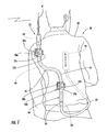
FIG. 1 is a rear view of a user carrying a communication system including the antenna in accordance with the present invention. -
FIG. 2 is an enlarged cross-sectional view through the noise filter of the antenna as shown inFIG. 1 . -
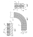
FIG. 3 is an enlarged cross-sectional view of a portion of the flexible electrically conductive sleeve of the antenna as shown inFIG. 1 and illustrating the sleeve in a temporarily bent shape. -
FIG. 4 is a greatly enlarged cross-sectional view through a sidewall portion of the flexible electrically conductive sleeve of the antenna shown inFIG. 1 . -
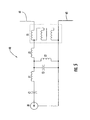
FIG. 5 is a schematic electrical diagram for the broadband matching network of the dipole feed of the antenna as shown inFIG. 1 . - The present invention will now be described more fully hereinafter with reference to the accompanying drawings in which preferred embodiments of the invention are shown. This invention may, however, be embodied in many different forms and should not be construed as limited to the illustrated embodiments set forth herein. Rather, these embodiments are provided so that this disclosure will be thorough and complete, and will fully convey the scope of the invention to those skilled in the art. Like numbers refer to like elements throughout, and prime notation is used to indicate similar elements in alternate embodiments.
- Referring initially to
FIG. 1 , the components of aportable communications system 20 in accordance with the invention are now described. Thesystem 20 includes aradio 21, and anantenna assembly 22 connected to the radio. Theradio 21 may be a portable unit, such as the model RF-5800V-HH that is a small, lightweight VHF handheld radio offered by Harris RF Communications Division of Rochester, New York, for example. The RF-5800V-HH operates over a broad frequency range of 30-108 MHz. Other possible frequencies may be used by theradio 21, such as, for example, the 420-450 MHz band. - The
antenna assembly 22 includes anantenna 25, a pair of upper andlower fasteners 26a, 26b and acoaxial cable 27 that connects theantenna 25 to theradio 21. Each of thefasteners 26a, 26b illustratively includes a conventional Aliceclip 30a, 30b that removable connects typically to webbing or a vest (not shown), for example, or other garment worn by theuser 35. For clarity of explanation, thefasteners 26a, 26b are illustrated in side view, that is rotated ninety degrees from the actual attached position as will be appreciated by those skilled in the art. - Each
fastener 26a, 26b illustratively includes an Aliceclip mounting bracket clip 20a, 30b, and a quick release knob 32a, 32B carried by the Alice clip mounting bracket. Of course, other configurations offasteners 26a, 26b are also contemplated by the present invention to permit wearing of theantenna 25 by theuser 35. - The
user 35 may also sometimes wish to remove theantenna 35 and raise it to a higher position, for example, for better range. Thefasteners 26a, 26b provide such flexibility to theuser 35 as will be appreciated by those skilled in the art. In other embodiments, only a single fastener, or more than two fasteners may be used. - The
antenna 25 includes a dipole feed comprising abroadband matching network 40 shown adjacent the upper fastener 26a. Thisbroadband matching network 40 is further described below with reference toFIG. 5 and helps provide broadband performance for theantenna 25. - The
antenna 25 also includes afirst dipole element 41 extending upwardly from the dipolefeed matching network 40. Thisfirst dipole element 41 may be formed of a series of progressively longer strip-shaped conductors to provide flexibility to the element as will be appreciated by those skilled in the art. Accordingly, thefirst dipole element 41 may be folded for storage and transportation, but when released will spring to the fully extended position. For the VHF range described above, this first dipole element may have a length of about 91.44 centimeter (thirty-six inches), for example. - The
antenna 25 also includes atransmission line 44 extending from the dipole feedbroadband matching network 40 in a downward direction. In other words, the transmission line extends in a second direction opposite the first direction of thefirst dipole element 41. Theantenna 25 also comprises a flexible electricallyconductive sleeve 45 surrounding thetransmission line 44 and connected to and extending outwardly from dipolefeed matching network 40. This flexible electricallyconductive sleeve 45 serves as a second dipole element and also as a balun to couple theunbalanced transmission line 44 to the dipole antenna elements as will be appreciated by those skilled in the art. For the VHF range described above, this flexibleconductive sleeve 45 may have a length of about 60.96 centimeter (twenty-four inches), for example. - The
antenna 25 also includes anoise filter 46 coupled to thetransmission line 44 adjacent the lower end of the flexible electricallyconductive sleeve 45. Aconnector 28 terminates thetransmission line 44 at thenoise filter 46 as shown. Theconnector 28 may be a BNC connector or any of a variety of suitable connectors as will be appreciated by those skilled in the art. A mating rotatable connector 29 illustratively connects the jumpercoaxial cable 27 to theconnector 28 at thenoise filter 46. The rotatable connector 29 may permit theuser 35 to swing thecoaxial cable 27 to either the right or left side of his body for comfort or convenience. Other pairs of mating connectors, not shown, may be provided along the length of the jumpercoaxial cable 27 in some embodiments. - This
noise filter 44 reduces interfering noise delivered from theantenna 25 to the receiver in theradio 21 as will be appreciated by those skilled in the art. Referring briefly toFIG. 2 , one embodiment of asuitable noise filter 46 is described. More particularly, the illustratednoise filter 46 includes a cylindricaldielectric housing 47 and a plurality of ferrite beads orbodies transmission line 44 and contained within the housing. Other configurations of noise filters are also contemplated by the present invention and will be apparent to those of skill in the art. - Referring now additionally to
FIGS. 3 and 4 , other aspects of theantenna 25 are now described. Thetransmission line 44 is illustratively provided by a coaxial arrangement of conductors. In particular, thetransmission line 44 includes aninner conductor 50, adielectric layer 51 surrounding the inner conductor, and anouter conductor 52 surrounding the dielectric layer. The flexibleconductive sleeve 45 surrounds thetransmission line 44 and is spaced therefrom by anotherdielectric layer 53 in the illustrated embodiment. Although thedielectric layer 53 is shown filing the space between theouter conductor 52 and thesleeve 45, in other embodiments the dielectric layer may be a thin layer on the outer conductor, or on the inside surface of the sleeve, and a space or air gap left between the thin dielectric layer and the adjacent conductive portion as will be appreciated by those skilled in the art. - The flexible electrically
conductive sleeve 45 may also be shape-retaining when formed into a shape having at least one bend therein, such as shown by the ninety degree bend inFIG. 3 . This bend is at the upper portion of the flexible electricallyconductive sleeve 45 between the upper fastener 26a and the dipolefeed matching network 40. Accordingly, if the user were oriented in a prone position, theconductive sleeve 45 could be temporarily bent at a ninety degree angle so that thefirst dipole element 41 remained vertically oriented for better performance. It should be noted that the electricallyconductive sleeve 45 may be readily bent by theuser 35 to conform to his body. Thesleeve 45 will also flex during movement by theuser 35 so as not to be restrictive. - The flexible electrically
conductive sleeve 45 may be formed of a solid conductor. In another preferred embodiment as shown inFIG. 4 , the flexible sleeve 45' may comprise a pair of spirally wound, interlocking, electricallyconductive elements 45a', 45b', for example. Other configurations are also envisioned as will be appreciated by those skilled in the art. - Turning now to
FIG. 5 , an embodiment of a dipole feedbroadband matching network 40 is now described. Thenetwork 40 includes a three winding transformer T1 connected across thedipole elements broadband matching networks 40 are also contemplated by the present invention. The illustratednetwork 40 has an advantage in that no resistors are used and therefore efficiency is higher than would otherwise result. - A method, not being part of the invention, is for making the
antenna 25 as described herein. The method may include coupling afirst dipole element 41 to and extend outwardly from adipole feed 40 in a first direction; coupling atransmission line 44 to extend from the dipole feed in a second direction opposite the first direction;
and providing a flexible electricallyconductive sleeve 45 surrounding the transmission line and coupled to and extending outwardly from the dipole feed to serve as a second dipole element and as a balun. The method may also include coupling anoise filter 46 to thetransmission line 44 adjacent an end of the flexible electricallyconductive sleeve 45 opposite thedipole feed 40.
Claims (11)
- An antenna assembly (22) to be worn by a user and comprising:an antenna (25) comprising
a dipole feed (40) comprising a broadband matching network (40),
said broadband matching network (40) comprises
a three winding transformer (T1) connected across a pair of dipole elements (41, 45),
a first capacitor (C1), a first inductor (L1), and a third inductor (L3) connected in series between an inner conductor of an input (IN) and the transformer (T1), and
a second capacitor (C2) and second inductor (L2) connected in parallel witch each other and across the transformer (T1) between the first and third inductors (L1, L3);
a first dipole element (41) connected to and extending outwardly from said dipole feed (40) in a first direction,
a transmission line (44) extending from said dipole feed (40) in a second direction opposite the first direction, and
a flexible electrically conductive sleeve (45) surrounding said transmission line (44) and connected to and extending outwardly from said dipole feed (40) to serve as a second dipole element and as a balun; and
at least one fastener (26a, 26b) to removably fasten the antenna (25) to a garment of the user. - An antenna assembly (22) according to Claim 1 further comprising a noise filter (46) coupled to said transmission line (44) adjacent an end of said flexible electrically conductive sleeve (45) opposite said dipole feed (40).
- An antenna assembly (22) according to Claim 2 wherein said noise filter (46) comprises at least one ferrite body (48a, 48b) coupled to said transmission line (44) and a dielectric housing (47) surrounding said at least one ferrite body (48a, 48b).
- An antenna assembly (22) according to any of the preceding claims wherein said flexible electrically conductive sleeve (45) is also shape-retaining when formed into a shape having at least one bend therein.
- An antenna assembly (22) according to any of the preceding claims wherein said flexible electrically conductive sleeve (45) comprises a pair of spirally wound, interlocking, electrically conductive elements (45a', 45b').
- An antenna assembly (22) according to any of the preceding claims wherein said at least one fastener (26a, 26b) comprises a pair of fasteners adjacent opposing ends of said flexible electrically conductive sleeve (45).
- An antenna assembly (22) according to any of the preceding claims wherein said at least one fastener (26a, 26b) comprises:an Alice clip (30a, 30b) to connect to the garment of the user;an Alice clip mounting bracket (31a, 31b) connected to said Alice clip; anda quick release knob (32a, 32b) carried by said Alice clip mounting bracket.
- An antenna assembly (22) according to any of the preceding claims wherein said first dipole element (41) comprises a flexible electrical conductor.
- An antenna assembly (22) according to any of the preceding claims further comprising a connector (28) coupled to an end of said transmission line opposite said dipole feed.
- An antenna assembly (22) according to any of the preceding claims further comprising a rotatable connector (29) for connecting the antenna assembly (22) to a coaxial cable (27) connected to a radio (21).
- An antenna assembly (22) according to Claim 3 wherein the housing (47) is a cylindrical dielectric housing (47) and wherein the at least one ferrite body (48a, 48b) includes a plurality of ferrite beads (48a, 48b) surrounding the transmission line (44) and contained within the housing (47).
Applications Claiming Priority (2)
| Application Number | Priority Date | Filing Date | Title |
|---|---|---|---|
| US665004 | 2003-09-19 | ||
| US10/665,004 US6940462B2 (en) | 2003-09-19 | 2003-09-19 | Broadband dipole antenna to be worn by a user and associated methods |
Publications (2)
| Publication Number | Publication Date |
|---|---|
| EP1517397A1 EP1517397A1 (en) | 2005-03-23 |
| EP1517397B1 true EP1517397B1 (en) | 2009-03-18 |
Family
ID=34194757
Family Applications (1)
| Application Number | Title | Priority Date | Filing Date |
|---|---|---|---|
| EP04021551A Expired - Lifetime EP1517397B1 (en) | 2003-09-19 | 2004-09-10 | Broadband dipole antenna to be worn by a user and associated methods |
Country Status (5)
| Country | Link |
|---|---|
| US (1) | US6940462B2 (en) |
| EP (1) | EP1517397B1 (en) |
| AT (1) | ATE426257T1 (en) |
| DE (1) | DE602004020035D1 (en) |
| IL (1) | IL163915A (en) |
Families Citing this family (21)
| Publication number | Priority date | Publication date | Assignee | Title |
|---|---|---|---|---|
| US7554829B2 (en) * | 1999-07-30 | 2009-06-30 | Micron Technology, Inc. | Transmission lines for CMOS integrated circuits |
| US7235457B2 (en) | 2002-03-13 | 2007-06-26 | Micron Technology, Inc. | High permeability layered films to reduce noise in high speed interconnects |
| US6846738B2 (en) * | 2002-03-13 | 2005-01-25 | Micron Technology, Inc. | High permeability composite films to reduce noise in high speed interconnects |
| US6970053B2 (en) * | 2003-05-22 | 2005-11-29 | Micron Technology, Inc. | Atomic layer deposition (ALD) high permeability layered magnetic films to reduce noise in high speed interconnection |
| US7927948B2 (en) | 2005-07-20 | 2011-04-19 | Micron Technology, Inc. | Devices with nanocrystals and methods of formation |
| US7969369B2 (en) * | 2007-07-11 | 2011-06-28 | Harris Corporation | Body-worn antenna fastening device and method |
| US7755553B2 (en) * | 2007-08-20 | 2010-07-13 | Harris Corporation | Multiband antenna system for body-worn and dismount applications |
| US8900188B2 (en) * | 2007-12-31 | 2014-12-02 | Deka Products Limited Partnership | Split ring resonator antenna adapted for use in wirelessly controlled medical device |
| JP2010021756A (en) * | 2008-07-10 | 2010-01-28 | Harris Corp | Wearable antenna fastening device and method |
| US8810463B2 (en) * | 2011-05-06 | 2014-08-19 | Jeffrey B. Kirkham | Antenna mount |
| TW201432999A (en) * | 2012-10-31 | 2014-08-16 | Galtronics Corp Ltd | Wideband whip antenna |
| US9343800B2 (en) | 2013-08-09 | 2016-05-17 | Motorola Solutions, Inc. | Flexible mounting apparatus for mounting an antenna |
| US9786990B2 (en) * | 2014-02-24 | 2017-10-10 | R.A. Miller Industries, Inc. | Integrated multiband antenna |
| US10784670B2 (en) * | 2015-07-23 | 2020-09-22 | At&T Intellectual Property I, L.P. | Antenna support for aligning an antenna |
| CN108886377B (en) * | 2016-03-22 | 2020-06-16 | 摩托罗拉解决方案公司 | Portable wearable radio including modular harness |
| US10868358B2 (en) * | 2017-10-19 | 2020-12-15 | Harris Solutions NY, Inc. | Antenna for wearable radio system and associated method of making |
| CN108183310B (en) * | 2018-01-30 | 2020-05-29 | 读书郎教育科技有限公司 | Intelligent wearable device |
| US11063345B2 (en) * | 2018-07-17 | 2021-07-13 | Mastodon Design Llc | Systems and methods for providing a wearable antenna |
| US11211685B2 (en) | 2019-12-06 | 2021-12-28 | Harris Global Communications, Inc. | Electrically neutral body contouring antenna system |
| US12199585B2 (en) | 2020-12-10 | 2025-01-14 | Skyworks Solutions, Inc. | Baluns with integrated matching networks |
| US12021301B2 (en) * | 2021-07-08 | 2024-06-25 | Thales Defense & Security, Inc. | Antenna gooseneck device and communication system to mitigate near-field effects of co-localized antennas on portable radio products and methods of use thereof |
Citations (1)
| Publication number | Priority date | Publication date | Assignee | Title |
|---|---|---|---|---|
| US4730195A (en) * | 1985-07-01 | 1988-03-08 | Motorola, Inc. | Shortened wideband decoupled sleeve dipole antenna |
Family Cites Families (23)
| Publication number | Priority date | Publication date | Assignee | Title |
|---|---|---|---|---|
| US2576128A (en) * | 1948-04-03 | 1951-11-27 | Motorola Inc | Man-pack antenna |
| US3523296A (en) * | 1967-04-25 | 1970-08-04 | Hellige & Co Gmbh F | Portable antenna |
| US3720874A (en) * | 1971-11-08 | 1973-03-13 | Motorola Inc | Dipole antenna arrangement for radio with separate speaker-microphone assembly |
| US3902118A (en) * | 1974-04-04 | 1975-08-26 | Us Army | Body-coupled portable transmitter |
| US4041394A (en) * | 1976-07-06 | 1977-08-09 | River Range Developments Limited | Radio control transmitter |
| US4205319A (en) * | 1978-05-05 | 1980-05-27 | Motorola, Inc. | Flexible dipole antenna for hand-held two-way radio |
| US4496953A (en) * | 1982-07-26 | 1985-01-29 | Rockwell International Corporation | Broadband vertical dipole antenna |
| JPS6477205A (en) * | 1987-06-27 | 1989-03-23 | Nippon Denso Co | Shared antenna equipment for vehicle |
| JP2985196B2 (en) * | 1989-11-01 | 1999-11-29 | 株式会社デンソー | Vehicle antenna device |
| US5127565A (en) * | 1990-08-15 | 1992-07-07 | Grant Kieran P | Ammunition dispensing garment |
| US5091732A (en) * | 1990-09-07 | 1992-02-25 | The United States Of America As Represented By The Secretary Of The Navy | Lightweight deployable antenna system |
| US5628057A (en) * | 1996-03-05 | 1997-05-06 | Motorola, Inc. | Multi-port radio frequency signal transformation network |
| US5949383A (en) * | 1997-10-20 | 1999-09-07 | Ericsson Inc. | Compact antenna structures including baluns |
| US6179666B1 (en) * | 1999-02-05 | 2001-01-30 | Michael L. Osborn | Two-way radio accessory quick connect and extension cord |
| US6424820B1 (en) * | 1999-04-02 | 2002-07-23 | Interval Research Corporation | Inductively coupled wireless system and method |
| US6215448B1 (en) * | 1999-07-30 | 2001-04-10 | Agilent Technologies | Broadband coupler for measurement of antenna signals |
| US6531988B1 (en) * | 1999-09-28 | 2003-03-11 | Seiko Epson Corporation | Antenna device for high-frequency radio apparatus, high-frequency radio apparatus, and watch-shaped radio apparatus |
| GB0002935D0 (en) * | 2000-02-10 | 2000-03-29 | Koninkl Philips Electronics Nv | Portable device antenna |
| US6356238B1 (en) * | 2000-10-30 | 2002-03-12 | The United States Of America As Represented By The Secretary Of The Navy | Vest antenna assembly |
| GB0100775D0 (en) * | 2001-01-11 | 2001-02-21 | Koninl Philips Electronics Nv | Garment antenna |
| US20030030591A1 (en) * | 2001-08-09 | 2003-02-13 | David Gipson | Sleeved dipole antenna with ferrite material |
| US6552692B1 (en) * | 2001-10-30 | 2003-04-22 | Andrew Corporation | Dual band sleeve dipole antenna |
| US6590540B1 (en) * | 2002-01-31 | 2003-07-08 | The United States Of America As Represented By The Secretary Of The Navy | Ultra-broadband antenna incorporated into a garment |
-
2003
- 2003-09-19 US US10/665,004 patent/US6940462B2/en not_active Expired - Fee Related
-
2004
- 2004-09-06 IL IL163915A patent/IL163915A/en not_active IP Right Cessation
- 2004-09-10 EP EP04021551A patent/EP1517397B1/en not_active Expired - Lifetime
- 2004-09-10 DE DE602004020035T patent/DE602004020035D1/en not_active Expired - Lifetime
- 2004-09-10 AT AT04021551T patent/ATE426257T1/en not_active IP Right Cessation
Patent Citations (1)
| Publication number | Priority date | Publication date | Assignee | Title |
|---|---|---|---|---|
| US4730195A (en) * | 1985-07-01 | 1988-03-08 | Motorola, Inc. | Shortened wideband decoupled sleeve dipole antenna |
Also Published As
| Publication number | Publication date |
|---|---|
| ATE426257T1 (en) | 2009-04-15 |
| IL163915A0 (en) | 2005-12-18 |
| US6940462B2 (en) | 2005-09-06 |
| EP1517397A1 (en) | 2005-03-23 |
| US20050062659A1 (en) | 2005-03-24 |
| DE602004020035D1 (en) | 2009-04-30 |
| IL163915A (en) | 2009-09-22 |
Similar Documents
| Publication | Publication Date | Title |
|---|---|---|
| EP1517397B1 (en) | Broadband dipole antenna to be worn by a user and associated methods | |
| CN112838370B (en) | Antenna components and electronic equipment | |
| US7755553B2 (en) | Multiband antenna system for body-worn and dismount applications | |
| US6590540B1 (en) | Ultra-broadband antenna incorporated into a garment | |
| US4868576A (en) | Extendable antenna for portable cellular telephones with ground radiator | |
| EP3474372A1 (en) | Antenna for wearable radio system and associated method of making | |
| US20130009832A1 (en) | Dual uhf dipole quadrafiler helix antenna | |
| KR20060002979A (en) | Variable tuned antenna and portable radio using the same | |
| EP0697139A1 (en) | Hand-held transmitting and/or receiving apparatus | |
| EP3229317B1 (en) | Communications device with conductive surface coupled to human body | |
| US11245286B2 (en) | Power receiving antenna configured in a wearable electronic device | |
| US20090015505A1 (en) | Antenna device with integrated connection cable, and radio apparatus | |
| JPH06276117A (en) | Portable radio equipment | |
| EP2529446B1 (en) | Body wearable antenna | |
| JP2022066356A (en) | Systems and methods for providing wearable antenna | |
| CN108574136B (en) | Wireless device antenna | |
| GB2036447A (en) | Aerial for Body-worn Radio Apparatus | |
| EP2355243A1 (en) | Body wearable antenna | |
| JPH03173227A (en) | Portable radio equipment | |
| WO2002056414A1 (en) | Apparatus for transmitting a signal |
Legal Events
| Date | Code | Title | Description |
|---|---|---|---|
| PUAI | Public reference made under article 153(3) epc to a published international application that has entered the european phase |
Free format text: ORIGINAL CODE: 0009012 |
|
| 17P | Request for examination filed |
Effective date: 20040910 |
|
| AK | Designated contracting states |
Kind code of ref document: A1 Designated state(s): AT BE BG CH CY CZ DE DK EE ES FI FR GB GR HU IE IT LI LU MC NL PL PT RO SE SI SK TR |
|
| AX | Request for extension of the european patent |
Extension state: AL HR LT LV MK |
|
| AKX | Designation fees paid |
Designated state(s): AT BE BG CH CY CZ DE DK EE ES FI FR GB GR HU IE IT LI LU MC NL PL PT RO SE SI SK TR |
|
| GRAP | Despatch of communication of intention to grant a patent |
Free format text: ORIGINAL CODE: EPIDOSNIGR1 |
|
| GRAS | Grant fee paid |
Free format text: ORIGINAL CODE: EPIDOSNIGR3 |
|
| GRAA | (expected) grant |
Free format text: ORIGINAL CODE: 0009210 |
|
| AK | Designated contracting states |
Kind code of ref document: B1 Designated state(s): AT BE BG CH CY CZ DE DK EE ES FI FR GB GR HU IE IT LI LU MC NL PL PT RO SE SI SK TR |
|
| REG | Reference to a national code |
Ref country code: GB Ref legal event code: FG4D |
|
| REG | Reference to a national code |
Ref country code: CH Ref legal event code: EP |
|
| REG | Reference to a national code |
Ref country code: IE Ref legal event code: FG4D |
|
| REF | Corresponds to: |
Ref document number: 602004020035 Country of ref document: DE Date of ref document: 20090430 Kind code of ref document: P |
|
| PG25 | Lapsed in a contracting state [announced via postgrant information from national office to epo] |
Ref country code: NL Free format text: LAPSE BECAUSE OF FAILURE TO SUBMIT A TRANSLATION OF THE DESCRIPTION OR TO PAY THE FEE WITHIN THE PRESCRIBED TIME-LIMIT Effective date: 20090318 Ref country code: SI Free format text: LAPSE BECAUSE OF FAILURE TO SUBMIT A TRANSLATION OF THE DESCRIPTION OR TO PAY THE FEE WITHIN THE PRESCRIBED TIME-LIMIT Effective date: 20090318 |
|
| PG25 | Lapsed in a contracting state [announced via postgrant information from national office to epo] |
Ref country code: PL Free format text: LAPSE BECAUSE OF FAILURE TO SUBMIT A TRANSLATION OF THE DESCRIPTION OR TO PAY THE FEE WITHIN THE PRESCRIBED TIME-LIMIT Effective date: 20090318 Ref country code: AT Free format text: LAPSE BECAUSE OF FAILURE TO SUBMIT A TRANSLATION OF THE DESCRIPTION OR TO PAY THE FEE WITHIN THE PRESCRIBED TIME-LIMIT Effective date: 20090318 Ref country code: SE Free format text: LAPSE BECAUSE OF FAILURE TO SUBMIT A TRANSLATION OF THE DESCRIPTION OR TO PAY THE FEE WITHIN THE PRESCRIBED TIME-LIMIT Effective date: 20090618 |
|
| NLV1 | Nl: lapsed or annulled due to failure to fulfill the requirements of art. 29p and 29m of the patents act | ||
| PG25 | Lapsed in a contracting state [announced via postgrant information from national office to epo] |
Ref country code: BE Free format text: LAPSE BECAUSE OF FAILURE TO SUBMIT A TRANSLATION OF THE DESCRIPTION OR TO PAY THE FEE WITHIN THE PRESCRIBED TIME-LIMIT Effective date: 20090318 |
|
| PG25 | Lapsed in a contracting state [announced via postgrant information from national office to epo] |
Ref country code: ES Free format text: LAPSE BECAUSE OF FAILURE TO SUBMIT A TRANSLATION OF THE DESCRIPTION OR TO PAY THE FEE WITHIN THE PRESCRIBED TIME-LIMIT Effective date: 20090629 Ref country code: EE Free format text: LAPSE BECAUSE OF FAILURE TO SUBMIT A TRANSLATION OF THE DESCRIPTION OR TO PAY THE FEE WITHIN THE PRESCRIBED TIME-LIMIT Effective date: 20090318 Ref country code: CZ Free format text: LAPSE BECAUSE OF FAILURE TO SUBMIT A TRANSLATION OF THE DESCRIPTION OR TO PAY THE FEE WITHIN THE PRESCRIBED TIME-LIMIT Effective date: 20090318 Ref country code: PT Free format text: LAPSE BECAUSE OF FAILURE TO SUBMIT A TRANSLATION OF THE DESCRIPTION OR TO PAY THE FEE WITHIN THE PRESCRIBED TIME-LIMIT Effective date: 20090826 |
|
| PG25 | Lapsed in a contracting state [announced via postgrant information from national office to epo] |
Ref country code: SK Free format text: LAPSE BECAUSE OF FAILURE TO SUBMIT A TRANSLATION OF THE DESCRIPTION OR TO PAY THE FEE WITHIN THE PRESCRIBED TIME-LIMIT Effective date: 20090318 Ref country code: RO Free format text: LAPSE BECAUSE OF FAILURE TO SUBMIT A TRANSLATION OF THE DESCRIPTION OR TO PAY THE FEE WITHIN THE PRESCRIBED TIME-LIMIT Effective date: 20090318 |
|
| PLBE | No opposition filed within time limit |
Free format text: ORIGINAL CODE: 0009261 |
|
| STAA | Information on the status of an ep patent application or granted ep patent |
Free format text: STATUS: NO OPPOSITION FILED WITHIN TIME LIMIT |
|
| PG25 | Lapsed in a contracting state [announced via postgrant information from national office to epo] |
Ref country code: BG Free format text: LAPSE BECAUSE OF FAILURE TO SUBMIT A TRANSLATION OF THE DESCRIPTION OR TO PAY THE FEE WITHIN THE PRESCRIBED TIME-LIMIT Effective date: 20090618 Ref country code: DK Free format text: LAPSE BECAUSE OF FAILURE TO SUBMIT A TRANSLATION OF THE DESCRIPTION OR TO PAY THE FEE WITHIN THE PRESCRIBED TIME-LIMIT Effective date: 20090318 |
|
| 26N | No opposition filed |
Effective date: 20091221 |
|
| PG25 | Lapsed in a contracting state [announced via postgrant information from national office to epo] |
Ref country code: FI Free format text: LAPSE BECAUSE OF NON-PAYMENT OF DUE FEES Effective date: 20090910 Ref country code: MC Free format text: LAPSE BECAUSE OF NON-PAYMENT OF DUE FEES Effective date: 20090930 |
|
| REG | Reference to a national code |
Ref country code: CH Ref legal event code: PL |
|
| REG | Reference to a national code |
Ref country code: IE Ref legal event code: MM4A |
|
| PG25 | Lapsed in a contracting state [announced via postgrant information from national office to epo] |
Ref country code: IE Free format text: LAPSE BECAUSE OF NON-PAYMENT OF DUE FEES Effective date: 20090910 |
|
| PG25 | Lapsed in a contracting state [announced via postgrant information from national office to epo] |
Ref country code: CH Free format text: LAPSE BECAUSE OF NON-PAYMENT OF DUE FEES Effective date: 20090930 Ref country code: LI Free format text: LAPSE BECAUSE OF NON-PAYMENT OF DUE FEES Effective date: 20090930 Ref country code: GR Free format text: LAPSE BECAUSE OF FAILURE TO SUBMIT A TRANSLATION OF THE DESCRIPTION OR TO PAY THE FEE WITHIN THE PRESCRIBED TIME-LIMIT Effective date: 20090619 |
|
| PG25 | Lapsed in a contracting state [announced via postgrant information from national office to epo] |
Ref country code: LU Free format text: LAPSE BECAUSE OF NON-PAYMENT OF DUE FEES Effective date: 20090910 |
|
| PG25 | Lapsed in a contracting state [announced via postgrant information from national office to epo] |
Ref country code: HU Free format text: LAPSE BECAUSE OF FAILURE TO SUBMIT A TRANSLATION OF THE DESCRIPTION OR TO PAY THE FEE WITHIN THE PRESCRIBED TIME-LIMIT Effective date: 20090919 |
|
| PG25 | Lapsed in a contracting state [announced via postgrant information from national office to epo] |
Ref country code: TR Free format text: LAPSE BECAUSE OF FAILURE TO SUBMIT A TRANSLATION OF THE DESCRIPTION OR TO PAY THE FEE WITHIN THE PRESCRIBED TIME-LIMIT Effective date: 20090318 |
|
| PG25 | Lapsed in a contracting state [announced via postgrant information from national office to epo] |
Ref country code: CY Free format text: LAPSE BECAUSE OF FAILURE TO SUBMIT A TRANSLATION OF THE DESCRIPTION OR TO PAY THE FEE WITHIN THE PRESCRIBED TIME-LIMIT Effective date: 20090318 |
|
| PGFP | Annual fee paid to national office [announced via postgrant information from national office to epo] |
Ref country code: GB Payment date: 20120925 Year of fee payment: 9 |
|
| PGFP | Annual fee paid to national office [announced via postgrant information from national office to epo] |
Ref country code: FR Payment date: 20121001 Year of fee payment: 9 Ref country code: IT Payment date: 20120921 Year of fee payment: 9 |
|
| PGFP | Annual fee paid to national office [announced via postgrant information from national office to epo] |
Ref country code: DE Payment date: 20120927 Year of fee payment: 9 |
|
| GBPC | Gb: european patent ceased through non-payment of renewal fee |
Effective date: 20130910 |
|
| REG | Reference to a national code |
Ref country code: FR Ref legal event code: ST Effective date: 20140530 |
|
| REG | Reference to a national code |
Ref country code: DE Ref legal event code: R119 Ref document number: 602004020035 Country of ref document: DE Effective date: 20140401 |
|
| PG25 | Lapsed in a contracting state [announced via postgrant information from national office to epo] |
Ref country code: GB Free format text: LAPSE BECAUSE OF NON-PAYMENT OF DUE FEES Effective date: 20130910 |
|
| PG25 | Lapsed in a contracting state [announced via postgrant information from national office to epo] |
Ref country code: DE Free format text: LAPSE BECAUSE OF NON-PAYMENT OF DUE FEES Effective date: 20140401 Ref country code: FR Free format text: LAPSE BECAUSE OF NON-PAYMENT OF DUE FEES Effective date: 20130930 Ref country code: IT Free format text: LAPSE BECAUSE OF NON-PAYMENT OF DUE FEES Effective date: 20130910 |