EP1517047A1 - A method for the pumping and delivering of multi-phase fluids, and an apparatus therefor - Google Patents
A method for the pumping and delivering of multi-phase fluids, and an apparatus therefor Download PDFInfo
- Publication number
- EP1517047A1 EP1517047A1 EP03425611A EP03425611A EP1517047A1 EP 1517047 A1 EP1517047 A1 EP 1517047A1 EP 03425611 A EP03425611 A EP 03425611A EP 03425611 A EP03425611 A EP 03425611A EP 1517047 A1 EP1517047 A1 EP 1517047A1
- Authority
- EP
- European Patent Office
- Prior art keywords
- chamber
- fluid
- pumping
- delivering
- pipeline
- Prior art date
- Legal status (The legal status is an assumption and is not a legal conclusion. Google has not performed a legal analysis and makes no representation as to the accuracy of the status listed.)
- Withdrawn
Links
- 239000012530 fluid Substances 0.000 title claims abstract description 115
- 238000005086 pumping Methods 0.000 title claims abstract description 41
- 238000000034 method Methods 0.000 title claims abstract description 29
- 238000003860 storage Methods 0.000 claims abstract description 21
- 241000219094 Vitaceae Species 0.000 claims abstract description 11
- 235000021021 grapes Nutrition 0.000 claims abstract description 11
- 238000002347 injection Methods 0.000 claims abstract 8
- 239000007924 injection Substances 0.000 claims abstract 8
- 238000007599 discharging Methods 0.000 claims description 5
- 230000005484 gravity Effects 0.000 claims description 4
- 238000011144 upstream manufacturing Methods 0.000 claims 1
- 239000007789 gas Substances 0.000 description 35
- 241000196324 Embryophyta Species 0.000 description 21
- 239000007787 solid Substances 0.000 description 10
- 239000007788 liquid Substances 0.000 description 5
- 239000000203 mixture Substances 0.000 description 4
- 230000002000 scavenging effect Effects 0.000 description 4
- 241000219095 Vitis Species 0.000 description 3
- 235000009754 Vitis X bourquina Nutrition 0.000 description 3
- 235000012333 Vitis X labruscana Nutrition 0.000 description 3
- 235000014787 Vitis vinifera Nutrition 0.000 description 3
- 238000011514 vinification Methods 0.000 description 3
- 230000006835 compression Effects 0.000 description 2
- 238000007906 compression Methods 0.000 description 2
- 229940087559 grape seed Drugs 0.000 description 2
- 230000003068 static effect Effects 0.000 description 2
- 238000013517 stratification Methods 0.000 description 2
- 239000000126 substance Substances 0.000 description 2
- 230000003213 activating effect Effects 0.000 description 1
- 125000004122 cyclic group Chemical group 0.000 description 1
- 239000000839 emulsion Substances 0.000 description 1
- 238000005265 energy consumption Methods 0.000 description 1
- 230000002879 macerating effect Effects 0.000 description 1
- 230000014759 maintenance of location Effects 0.000 description 1
- 239000000463 material Substances 0.000 description 1
- 238000011084 recovery Methods 0.000 description 1
- 230000001105 regulatory effect Effects 0.000 description 1
- 239000004575 stone Substances 0.000 description 1
Images


Classifications
-
- F—MECHANICAL ENGINEERING; LIGHTING; HEATING; WEAPONS; BLASTING
- F04—POSITIVE - DISPLACEMENT MACHINES FOR LIQUIDS; PUMPS FOR LIQUIDS OR ELASTIC FLUIDS
- F04F—PUMPING OF FLUID BY DIRECT CONTACT OF ANOTHER FLUID OR BY USING INERTIA OF FLUID TO BE PUMPED; SIPHONS
- F04F1/00—Pumps using positively or negatively pressurised fluid medium acting directly on the liquid to be pumped
- F04F1/06—Pumps using positively or negatively pressurised fluid medium acting directly on the liquid to be pumped the fluid medium acting on the surface of the liquid to be pumped
Definitions
- the present invention relates to a method for the pumping of a multi-phase fluids, and more precisely, to a plant adopting a method for the pumping of a multi-phase fluids by means of compressed air, gases or steams and an apparatus therefor.
- the main object of the present invention is to solve the abovementioned problems by providing a method for the pumping of fluids and/or mixtures thereof, having solid parts therein, i.e. like sludges, emulsions, macerating fluids, and an apparatus for such method.
- a specific object of the present invention is to provide a method for the pumping of pressed grapes and marcs and an apparatus therefor, which solves said problems and having all the suitable features for pumping and delivering such a multi-phase fluid.
- the fluid is pumped and delivered by avoiding that the same come into contact with mechanical components and/or parts in motion, by receiving the energy required for the pumping and the delivering thereof from a source of compressed air or a specific gas, steam, with which it is in contact.
- the same allows to pump and deliver fluids, in particular those from a crop of grapes or the like, and avoids at the same time further grape ruptures, but above all grape seed ruptures, with the entailed discharge of oily substances harmful to the subsequent wine-making processes.
- the present invention provides a method for the pumping of multi-phase fluids according to claim 1.
- the present invention provides an apparatus for the pumping of multi-phase fluids according to claim 2.
- the plant has a storage tank 1 for the fluid to be pumped, said tank being pneumatically connected to a pair of pressurization chambers 2 and 3. Said chambers are located at a height higher than that of the storage tank 1, so that an apparatus for charging the fluid from the latter to the former is required.
- vacuum be generated by a pump 4 connected to the chambers 2 and 3 and in such a manner that, upon activating the pump 4, said chambers be charged with the fluid sucked in from the storage tank 1.
- the tank 1 be connected to a feed pipeline 11 which in turn is connected to two pipelines 12 and 13 respectively for sending the fluid to be pumped to the pressurization chambers 2 and 3 (hereinafter referred to merely as chambers).
- the pipelines 11, 12, 13 are connected thereamong by an on-off valve 5, which, in this specific case, is a 3-way valve.
- the two chambers 2 and 3 are equipped with bottom and top level gauges L2M, L2m, L3M, L3m and pressure gauges P2, P3, respectively.
- a container 34 functioning as a reservoir for the containing of the surging of the fluid coming from the chambers 2 and 3.
- a vacuum pump group 4 connected to relevant pipelines 20, 21, 22, 23, 24 and 27.
- Said pipelines are pneumatically connected by means of on-off valves 7, 8, 9 and 10, and in the specific case are of the 3-way kind.
- the chambers 2 and 3 have respective fluid outlets with relevant pipelines 14 and 15, the former being connected to a pipeline 16 by an on-off valve 6 that, in the specific case, is of the 3-way kind.
- the plant according to the invention further provides pipelines 17, 18 and 19 for the sending of pressurizing gas that are respectively connected to the pipelines 20 and 21, in order to pressurize (when required) the chambers 2 and 3 by means of the related on-off valves 7 and 8.
- a pipeline 29 which is connected to the pipeline 16 of the fluid coming from the chambers, by means of a regulating valve 31, in order to send the gas to fluidify the fluid pumped and delivered in the pipeline 16.
- a by-pass pipeline 30 from the pipeline 17 for the sending of gas to the reservoir 34 by a suitable inlet valve 32 and a related bleeder 33.
- pipelines 20, 21, 22, 23, 24, 25 serve (alternatively and when required) as scavenging pipelines for the de-pressurizing of the gas from the chambers 2 and 3, since the former are connected also to a pipeline 26 by the relevant on-off valves 7, 8, 9 and 10.
- FIG. 2 shows an alternative embodiment of the plant of the present invention, wherein for the charging of the chambers 2 and 3 no vacuum but rather another known apparatus is used.
- the chambers 2 and 3 are positioned at a height lower than the height of the storage tank 1, so that the fluid to be pumped may be sent in the former by gravity.
- an on/off valve 11C onto the inlet pipeline 11 there are provided an on/off valve 11C and (when required) a classifier/separator 1A for large-sized solid parts.
- the classifier is a component which is already known to the relevant state of the art.
- a pipeline 11A is provided on the classifier/separator 1A for the removal of the separated large-sized solid parts.
- a pipeline 11B for the feeding of the fluid to be pumped to the chambers 2 and 3 with the related on-off valve 5.
- the fluid to be pumped is introduced in the chambers 2 and/or alternatively 3. Then, it is pressurized by the pressurising gas via the pipelines 20 and 21 until the internal pressure of the relevant chamber reaches a predetermined value, which is sufficient to bias the fluid out the relevant chamber by transferring it through the pipelines 14 and/or 15 to the pipeline 16.
- the plant operates in a steady manner, and is controlled by a microprocessor control unit of the kind already known to the state of the art, whereas the operating logic of such control unit consists of the individual steps cyclically repeated on each individual chamber.
- the charging and discharging cycle for the chambers 2 and 3 is repeated, starting over from step A1 or A2 to step C as described above, thereby carrying out a determined series of cycles, on each individual chamber, as follows: A1-B-C-A1-B-C-A1- ..etc, or when the charging mode is A2, then: A2-B-C-A2-B-C-A2-B-C-A2-..etc.
- Step A charging of the fluid to be pumped.
- This operative mode comprises the vacuum-aided use of the fluid charging apparatus.
- the fluid to be pumped, stored in the tank 1, is sucked in the chamber 2 or 3 by means of the action of the partial vacuum therein, generated by a suitable apparatus 4 and transferred to the chamber 2 or 3 via the pipelines 27, 24, 23 and 21 (when the chamber involved is chamber 3), or alternatively via the pipelines 27, 24, 22 and 20 (when the chamber involved is chamber 2) with continuous interconnection ensured by the suitable position of the valves 9 and 8 (for chamber 3) and the valves 10 and 7 (for chamber 2).
- the filling condition of the chamber 2 and 3 by the fluid so transferred is signalled by the upper-level gauge L2M for chamber 2, and upper-level gauge L3M for chamber 3.
- the plant control apparatus closes the connecting pipeline between the chamber 2 and/or 3 and the fluid storage tank 1, by means of the positioning of the valve 5 between the chamber 2 and/or 3, and the vacuum group 4, by means of the suitable positioning of the valves 7 and 10 (when the chamber involved is chamber 2), and the valves 8 and 9 (when the chamber involved is chamber 3).
- this mode envisages the use of a non-vacuum-aided charging of the fluid in the chambers 2-3.
- the fluid to be pumped is in the pipeline 11 and it is percolated in the separator 1A by opening the valve 11C.
- pipelines 20 and 22 when the chamber involved is chamber 2
- pipelines 21 and 23 when the chamber involved is chamber 3
- the correct positioning of the relevant valves 7 or 8 the gas in the chambers 2 and/or 3 is expelled, thereby allowing a rapid and complete filling of the chambers.
- the filling of the chamber by the fluid to be transferred is signalled by the upper-level gauge (detector) L2M or L3M.
- control unit intercepts, by means of the correct positioning of the valve 5, the pipelines 11B or 12, or 11B and 13 which supply fluid to the chamber.
- Step B pressurizing and emptying of the fluid from the chambers 2 and/or 3 and transfer thereof to the desired destination.
- the transfer of the fluid is attained by the pressure exerted thereon by a pressurized gas or steam, in particular air, supplied from a suitable pipeline, and with the following modes:
- valve 6 is positioned so as to give continuity to the pipelines 14 and 16 (when the chamber to be emptied is chamber 2), or between the pipelines 15 and 16 (when the chamber to be emptied is chamber 3).
- valves 7 or 8 are positioned so as to give continuity to the pipelines 18 and 20 (when the chamber to be emptied is chamber 2), or between the pipelines 19 and 21 (when the chamber to be emptied is chamber 3).
- the pressurizing gas from the pipeline 17 enters the chamber to which the latter is connected, increasing the inner chamber pressure until reaching a predetermined pressure value which allows to bias the fluid via the pipelines 14 or 15, and then into the pipeline 16.
- the control unit switches the valve 6 so that the pipelines related to the scavenging of the fluid, i.e. the pipelines 14 and 16, or the pipelines 15 and 16, are intercepted.
- the relevant chamber is emptied of the fluid to be pumped and filled with the pressurizing gas at a determined pressure.
- Step C Depressurising of the chambers.
- step B Upon ending the fluid emptying step as indicated in the preceding step B, it is necessary to scavenge the pressurizing gas in the chamber, so that the latter be in conditions suitable to start a new charging cycle starting from step A1 or A2.
- the depressurising is carried out by commuting the valves 7 and 10 so as to give continuity to pipelines 20, 22 and 25 (when the chamber to be emptied is chamber 2), or by commuting the valves 8 and 9 so as to give continuity to the pipelines 21, 23 and 26 (when the chamber to be emptied is chamber 3).
- the scavenging of the gas is attained by positioning the valve 7 or the valve 8 so as to give continuity to the pipelines 20 and 22 (when the chamber involved is chamber 2), or the pipelines 21 and 23 (when the chamber involved is chamber 3).
- the depressurising ends when the internal pressure of the chamber being emptied reaches a predetermined value detected by P2 or P3, and in the case of the embodiment of Figure 2 is equal to the ambient pressure.
- the plant described hereto refers to a plant using 3-way valves, and this implies a congruous timing of the work steps. More precisely, the time sharing of the steps should be such that the concomitance of different positions be not required to each individual valve. When it is not possible to share the timing of the steps to comply with the above, each 3-way valve should be replaced by 2 way valves.
- the plant of the present invention can adopt specific devices in order to optimise its operation and energy consumption.
- a first device consists in adjusting the rate by reservoir. More precisely, there is provided the option of inserting onto the fluid delivery pipeline 16 a reservoir 34, a per se known apapratus, for the containing of gas and fluid and having the function of adjusting the rate by dampening the throbs induced by the sequence of the chamber discharging steps.
- the reservoir 34 receives the gas required to its operation by means of the pipeline 30 equipped with the valves 32 and 33.
- the valve 32 adjusts the inlet gas and the valve 33 adjusts the relief thereof.
- a second device consists in adjusting the rate by the fluidifying of the delivery pipelines. More precisely, in case of pumping of fluids having a high viscosity, or in case of multi-phase fluids (where there is a sufficient difference between the liquid component density and the solid component density, such as to foster the stratification of these two phases even in short times of absence of a mixing thereof), there may become necessary a device to keep in motion the fluid into the delivery pipelines 16, even when there is no chamber being emptied and the fluid would be still in said pipelines.
- This device allows attaining at least 3 advantages.
- a first advantage lies in that by keeping the pumped fluid always in motion in the delivery pipeline it is prevented that, at the start of the step of emptying the chambers, the pressure in the latter should overcome the static friction (which is related to the delivery pipeline section 16), to be capable of pumping and delivering the fluid.
- static friction being greater than dynamic friction
- the pressure required for the pumping and delivering of the fluid is greater than the pressure required in case the fluid in the pipeline 16 is already in motion. Then, with such arrangement, the pumped fluid in the pipeline 16 undergoes no excessive pressure raises, thereby preventing phenomena of excessive compression of the fluid itself, pipeline vibrations, and noise.
- a second advantage lies in that, by keeping the pumped fluid always in motion by adding gas or steam, there is obtained a mixture having at least two phases, liquid and gaseous, giving it a certain degree of compressibility, thereby allowing to adjust the rate even without the aid of a reservoir (as previously indicated in Figure 1 by the reference number 34).
- a third advantage lies in that, in case the pumped fluid is a multi-phase and with a sufficient diversity of density between the solid component and the liquid component, by keeping the pumped fluid always in motion its tendency to a rapid stratification is so prevented.
- a third device consists in the use of the pressurising gas or steam in the step of depressurising the chambers to generate the vacuum required to the filling thereof.
- the pressurising steam or gas at the instant of the expelling thereof from the chambers after the step of pressurizing, and prior to the discharge of the same outside, can be used as a driving fluid to activate a device 36 which exploits the pressure thereof to generate vacuum in the dedicated pipelines 24, 27 and 37 and in the related storage unit 35.
- this device 36 will be effected considering the energy content recoverable from the pressurizing gas or steam. I.e., the higher is the loss of pressure on the delivery pipelines 16 to overcome in order to transfer the pumped fluid, the higher will be the value of the gas or steam pressure at the instant of depressurising the chambers and, accordingly, the higher the attainable energy recovery.
- the device 36 is based on a known apparatus that generates vacuum by exploiting gas or steam energy. More precisely, it is based on expansions suitably made in converging and diverging ducts commonly known as ejectors.
- an empty storage unit 35 equipped with a pressure gauge P4, a vacuum-generating ejector 36, a pipeline connecting the ejector to the vacuum pipeline 37 provided with a valve 38, an on/off valve 39 located between the vacuum pump 4 and the storage unit 35, a pipeline 40 for relief pressurizing gases or steams toward the outside.
- the pressure gauge P4 that is connected to the storage unit 35, sets a bottom value P4L and a top value P4H.
- the control unit continuously compares the value of the pressure existing in the pipeline 37 and detected by P5 (P5i) to the value detected by P4 (P4i).
- 'P4S' is a number ranging from “P4H” to "P4L” and usually equal to (P4H + P4L)/2; and 'd' is a number depending from the geometrical features of the lines 27 and 37, which usually, yet without limiting generality, ranges from 0.1 to 0.3:
- valves 9 and 10 do not connect the pipeline 23 to the pipeline 26, or the pipeline 22 to the pipeline 25, i.e. when the chambers 2 or 3 are not being depressurised, vacuum is generated and held exclusively by the pump group 4, by opening the valve 39 when P4i > P4H .
- the same valve 39 will be closed again when P4i ⁇ P4L, whereas the valve 38 stays always closed.
- the present invention entails countless advantages.
- a first advantage lies in that the charging of the fluid to be transferred into the chambers could be carried out by the aid of vacuum or of any other known apparatus, or alternatively by mere gravity according to the heights at which the machines are installed, or alternatively by pressure of the fluid itself in the fluid storage tank or reservoir prior to the pumping.
- a second advantage lies in that the chambers can have different features and geometrical shapes and be in any one number.
- a further advantage lies in that the fluid being transferred, apart from the valves, does not come into contact with any mechanical components in motion, such pump elements, etc.
- pressurizing gas may be air, gas, steam or any one mixture thereof.
- Another advantage lies in that in specific cases, in the step of pressurizing, in lieu of a gas or steam a liquid or even any other multi-phase fluid can be used.
- pressurizing gas could be provided by a suitable distribution network, or coming from suitable storages, or being provided on site by compression systems.
- Another advantage lies in that the pressure of the pressurizing gas is adjusted by known machines and apparatuses, thereby allowing a simple implementation of the plant.
- pressurizing gas may be injected where required, i.e. at one or more sites in the chambers or in the lines of the fluid to be transferred connected thereto.
- the fluid to be transferred can be a generic multi-phase fluid with liquid and solid components, pressed grapes and marcs as specific cases.
- Another advantage lies in that the pressurizing gas is used, at the instant of discharging from the pressurization chamber, as a driving fluid in a device apt to generate vacuum.
- Another advantage lies in that there may be or not be the total or partial control of the levels of fluid in the chambers.
- a further advantages lies in that the levels of filling and/or emptying of the chambers may be any one ranging between the minimum level and the maximum level.
- Another advantage lies in that there may be injected gas or steam in the delivery pipeline of the pumped fluid, to promote the transfer of the fluid.
- Another advantage lies in that the in the delivery pipeline there could be inserted a container which partially filled with air, gas, or steam could promote the evenness of the rate by throb dampening.
- a further advantages lies in that the evenness of the rate could be obtained by injecting gas or steam in the delivery pipeline of the pumped fluid.
- Another advantage lies in that the dampening of the surging of the pumped fluid is attained by injecting gas or steam in the delivery pipeline itself.
Landscapes
- Engineering & Computer Science (AREA)
- Mechanical Engineering (AREA)
- General Engineering & Computer Science (AREA)
- Jet Pumps And Other Pumps (AREA)
Abstract
Method and an apparatus for the pumping and delivering of
fluids, without the use of mechanical components in
motion, characterised in that it provides the charging of
a fluid to be pumped from a storage tank (1) toward at
least one chamber (2,3), the closing and the pressurizing
of the chamber (2,3) by means of the injection of a gas;
and the subsequent opening of the chamber (2,3) to flow
the fluid toward a second pipeline (16). The method and
the relevant apparatus are particularly indicated for the
pumping and delivering of pressed grapes and mares.
Description
- The present invention relates to a method for the pumping of a multi-phase fluids, and more precisely, to a plant adopting a method for the pumping of a multi-phase fluids by means of compressed air, gases or steams and an apparatus therefor.
- As it is widely known, there are several methods and apparatuses for pumping the most varied fluids with different modes. However, problems subsist related to the fact that there are provided pumping apparatuses not always congruous to the features required by fluid to be pumped.
- In particular, to date a problem occurs in the field of the transfer of multi-phase fluids when it is required that no mechanical actions, like excessive pinch or squashing, be exerted on the solid parts in the fluid to be pumped, or when the latter contains solid parts sufficiently hard to be capable of wearing and seizing the mechanical components (in motion and not in motion) of the machines in charge of the pumping.
- This is particularly required in the case of transferring pressed grapes for the wine-making process, where it is crucial that during the pumping and delivering thereof there occur no further grape ruptures, but above all no grape seed rupture, with the entailed discharge of oily substances harmful to the subsequent wine-making processes.
- Moreover, there is a further problem in the case of pressed grapes, when the latter are obtained from mechanically harvested grapes, as in the former there may be parts of vine shoots and stone materials that, during the pumping and delivering thereof with traditional apparatuses which use mechanical components in motion, can seriously damage the mechanical parts of the apparatus itself. Furthermore, in many cases, the presence of solid parts in the pressed grapes can hinder the proper operation of the mechanical parts of the pumping devices.
- The main object of the present invention is to solve the abovementioned problems by providing a method for the pumping of fluids and/or mixtures thereof, having solid parts therein, i.e. like sludges, emulsions, macerating fluids, and an apparatus for such method.
- A specific object of the present invention is to provide a method for the pumping of pressed grapes and marcs and an apparatus therefor, which solves said problems and having all the suitable features for pumping and delivering such a multi-phase fluid.
- According to a first advantageous aspect of the method and of the apparatus of the present invention, the fluid is pumped and delivered by avoiding that the same come into contact with mechanical components and/or parts in motion, by receiving the energy required for the pumping and the delivering thereof from a source of compressed air or a specific gas, steam, with which it is in contact.
- According to another advantageous aspect of the method and the apparatus of the present invention, the same allows to pump and deliver fluids, in particular those from a crop of grapes or the like, and avoids at the same time further grape ruptures, but above all grape seed ruptures, with the entailed discharge of oily substances harmful to the subsequent wine-making processes.
- Hence, the present invention provides a method for the pumping of multi-phase fluids according to claim 1.
- Moreover, the present invention provides an apparatus for the pumping of multi-phase fluids according to
claim 2. - Hereinafter, there will be provided a detailed description of a preferred embodiment of the method and the apparatus of the present invention, given by way of example and not for limitative purposes, making reference to the annexed drawings, wherein:
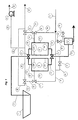
- Figure 1 is a schematic view of a first embodiment of a plant for the pumping and delivering of fluids according to the present invention;
- Figure 2 is a schematic detailed view of a part of the plant depicted in Figure 1; and
- Figure 3 is a schematic view of a second embodiment of a plant for the pumping and delivering of fluids according to the present invention.
-
- It has to be specified that the description hereinafter of the plant for the pumping and delivering of a multi-phase fluids of the present invention, is specifically designed for the transfer of the pressed grapes and/or marcs, where it is required that during its pumping and delivering no further ruptures of the grapes or grape seeds occur. However, it will be apparent to persons skilled in the art that the plant described in the present invention is perfectly suitable also for the pumping and delivering of other kinds of fluids, multi-phase or not and mixtures thereof. Hence, it is understood that the present invention is extended also to all the application fields of fluid transfer.
- With reference now to Figure 1 and according to the present invention, the plant has a storage tank 1 for the fluid to be pumped, said tank being pneumatically connected to a pair of
pressurization chambers pump 4 connected to thechambers pump 4, said chambers be charged with the fluid sucked in from the storage tank 1. - More precisely, according to the plant of the present invention, it is provided that the tank 1 be connected to a
feed pipeline 11 which in turn is connected to twopipelines pressurization chambers 2 and 3 (hereinafter referred to merely as chambers). Thepipelines valve 5, which, in this specific case, is a 3-way valve. - The two
chambers - Moreover, downstream of the
chambers container 34 functioning as a reservoir for the containing of the surging of the fluid coming from thechambers - On the other hand, to depressurise the
chambers vacuum pump group 4 connected torelevant pipelines valves - The
chambers relevant pipelines pipeline 16 by an on-offvalve 6 that, in the specific case, is of the 3-way kind. - As it will be better understood hereinafter, the plant according to the invention further provides
pipelines pipelines chambers valves - Moreover, there is provided a
pipeline 29 which is connected to thepipeline 16 of the fluid coming from the chambers, by means of a regulatingvalve 31, in order to send the gas to fluidify the fluid pumped and delivered in thepipeline 16. - Likewise, there is provided a by-
pass pipeline 30 from thepipeline 17 for the sending of gas to thereservoir 34 by asuitable inlet valve 32 and arelated bleeder 33. - Moreover, it is provided that the
pipelines chambers pipeline 26 by the relevant on-offvalves - With reference now to Figure 2, it shows an alternative embodiment of the plant of the present invention, wherein for the charging of the
chambers chambers - More precisely, onto the
inlet pipeline 11 there are provided an on/offvalve 11C and (when required) a classifier/separator 1A for large-sized solid parts. The classifier is a component which is already known to the relevant state of the art. - A
pipeline 11A is provided on the classifier/separator 1A for the removal of the separated large-sized solid parts. On the other hand, there is further provided apipeline 11B for the feeding of the fluid to be pumped to thechambers valve 5. - For clarity's sake, component parts illustrated in Figure 2 which have the same functional features of the component parts illustrated in Figure 1, will have the same reference number. Hence, a detailed description thereof will be here omitted, as already given with reference to Figure 1.
- The operation of the plant of the present invention is illustrated hereinafter.
- Firstly, the fluid to be pumped is introduced in the
chambers 2 and/or alternatively 3. Then, it is pressurized by the pressurising gas via thepipelines pipelines 14 and/or 15 to thepipeline 16. - It has to be specified that according to the present invention, the plant operates in a steady manner, and is controlled by a microprocessor control unit of the kind already known to the state of the art, whereas the operating logic of such control unit consists of the individual steps cyclically repeated on each individual chamber.
- More precisely, the cyclic steps are as follows:
- Step A - charging of the fluid to be pumped in the
chambers 2 and 3 (A1-mode when the charging apparatus uses vacuum, or A2-mode when the charging apparatus uses other methods or gravity); - Step B - pressurising and emptying of the fluid from
the
chambers - Step C - depressurising of the
chambers -
- Therefore, the charging and discharging cycle for the
chambers - Hereinafter, there will be provided a more detailed explanation for each step of the process highlighted above, and with reference to Figure 1.
- This operative mode comprises the vacuum-aided use of the fluid charging apparatus.
- The fluid to be pumped, stored in the tank 1, is sucked in the
chamber suitable apparatus 4 and transferred to thechamber pipelines pipelines valves 9 and 8 (for chamber 3) and thevalves 10 and 7 (for chamber 2). - The filling condition of the
chamber chamber 2, and upper-level gauge L3M forchamber 3. - When the chamber is filled, the plant control apparatus closes the connecting pipeline between the
chamber 2 and/or 3 and the fluid storage tank 1, by means of the positioning of thevalve 5 between thechamber 2 and/or 3, and thevacuum group 4, by means of the suitable positioning of thevalves 7 and 10 (when the chamber involved is chamber 2), and thevalves 8 and 9 (when the chamber involved is chamber 3). - With reference to Figure 2, this mode envisages the use of a non-vacuum-aided charging of the fluid in the chambers 2-3.
- The fluid to be pumped is in the
pipeline 11 and it is percolated in theseparator 1A by opening thevalve 11C. Via thepipeline 11A there are outletted solid parts having geometrical dimensions greater than a predetermined value (which is set according to the features of theseparator 1A), whereas the fluid to be pumped is transferred via thepipeline 11B, owing to the suitable positioning of thevalve 5 and the use of thepipelines relevant chamber 2 and/or 3. - During the filling step,
pipelines 20 and 22 (when the chamber involved is chamber 2), orpipelines 21 and 23 (when the chamber involved is chamber 3), and the correct positioning of therelevant valves chambers 2 and/or 3 is expelled, thereby allowing a rapid and complete filling of the chambers. The filling of the chamber by the fluid to be transferred is signalled by the upper-level gauge (detector) L2M or L3M. - When the chamber is filled, the control unit intercepts, by means of the correct positioning of the
valve 5, thepipelines - Hereinafter, unless otherwise stated, reference will be made to Figure 1.
- The transfer of the fluid is attained by the pressure exerted thereon by a pressurized gas or steam, in particular air, supplied from a suitable pipeline, and with the following modes:
- Firstly, the
valve 6 is positioned so as to give continuity to thepipelines 14 and 16 (when the chamber to be emptied is chamber 2), or between thepipelines 15 and 16 (when the chamber to be emptied is chamber 3). - Then, the
valves pipelines 18 and 20 (when the chamber to be emptied is chamber 2), or between thepipelines 19 and 21 (when the chamber to be emptied is chamber 3). - Following the preceding steps, the pressurizing gas from the
pipeline 17 enters the chamber to which the latter is connected, increasing the inner chamber pressure until reaching a predetermined pressure value which allows to bias the fluid via thepipelines pipeline 16. - At this stage, when the fluid level gauge Lm2 or Lm3 indicates that the latter has reached a determined emptying or volume, the control unit switches the
valve 6 so that the pipelines related to the scavenging of the fluid, i.e. thepipelines pipelines - Then, the relevant chamber is emptied of the fluid to be pumped and filled with the pressurizing gas at a determined pressure.
- Upon ending the fluid emptying step as indicated in the preceding step B, it is necessary to scavenge the pressurizing gas in the chamber, so that the latter be in conditions suitable to start a new charging cycle starting from step A1 or A2.
- In the case of the embodiment illustrated in Figure 1, the depressurising is carried out by commuting the
valves pipelines valves pipelines - In the case of the embodiment illustrated in Figure 2, the scavenging of the gas is attained by positioning the
valve 7 or thevalve 8 so as to give continuity to thepipelines 20 and 22 (when the chamber involved is chamber 2), or thepipelines 21 and 23 (when the chamber involved is chamber 3). - However, in both embodiments, the depressurising ends when the internal pressure of the chamber being emptied reaches a predetermined value detected by P2 or P3, and in the case of the embodiment of Figure 2 is equal to the ambient pressure.
- At this stage, the working cycle on the involved chamber is completed, and it is possible to restart the cycle from the initial step A of charging of the fluid to be transferred in the relevant chamber.
- The plant described hereto refers to a plant using 3-way valves, and this implies a congruous timing of the work steps. More precisely, the time sharing of the steps should be such that the concomitance of different positions be not required to each individual valve. When it is not possible to share the timing of the steps to comply with the above, each 3-way valve should be replaced by 2 way valves.
- Moreover, depending on the features required to the flow of the pumped fluid from the chambers, on the typology of the fluid itself, and on other contingent conditions, the plant of the present invention can adopt specific devices in order to optimise its operation and energy consumption.
- A first device consists in adjusting the rate by reservoir. More precisely, there is provided the option of inserting onto the fluid delivery pipeline 16 a
reservoir 34, a per se known apapratus, for the containing of gas and fluid and having the function of adjusting the rate by dampening the throbs induced by the sequence of the chamber discharging steps. - The
reservoir 34 receives the gas required to its operation by means of thepipeline 30 equipped with thevalves valve 32 adjusts the inlet gas and thevalve 33 adjusts the relief thereof. - A second device consists in adjusting the rate by the fluidifying of the delivery pipelines. More precisely, in case of pumping of fluids having a high viscosity, or in case of multi-phase fluids (where there is a sufficient difference between the liquid component density and the solid component density, such as to foster the stratification of these two phases even in short times of absence of a mixing thereof), there may become necessary a device to keep in motion the fluid into the
delivery pipelines 16, even when there is no chamber being emptied and the fluid would be still in said pipelines. - This device allows attaining at least 3 advantages.
- A first advantage lies in that by keeping the pumped fluid always in motion in the delivery pipeline it is prevented that, at the start of the step of emptying the chambers, the pressure in the latter should overcome the static friction (which is related to the delivery pipeline section 16), to be capable of pumping and delivering the fluid. As it is known, static friction being greater than dynamic friction, also the pressure required for the pumping and delivering of the fluid is greater than the pressure required in case the fluid in the
pipeline 16 is already in motion. Then, with such arrangement, the pumped fluid in thepipeline 16 undergoes no excessive pressure raises, thereby preventing phenomena of excessive compression of the fluid itself, pipeline vibrations, and noise. - A second advantage lies in that, by keeping the pumped fluid always in motion by adding gas or steam, there is obtained a mixture having at least two phases, liquid and gaseous, giving it a certain degree of compressibility, thereby allowing to adjust the rate even without the aid of a reservoir (as previously indicated in Figure 1 by the reference number 34).
- A third advantage lies in that, in case the pumped fluid is a multi-phase and with a sufficient diversity of density between the solid component and the liquid component, by keeping the pumped fluid always in motion its tendency to a rapid stratification is so prevented.
- The above is obtained with the continuous or discontinuous adding of air, gas or steam in the scavenging
pipeline 16 of the pumped fluid, and by means of the use of thepipeline 29 and of thevalve 31. In case of a discontinuous addition, this may be carried out by a timed apparatus for opening and closing thevalve 31. - A third device consists in the use of the pressurising gas or steam in the step of depressurising the chambers to generate the vacuum required to the filling thereof.
- More precisely, the pressurising steam or gas, at the instant of the expelling thereof from the chambers after the step of pressurizing, and prior to the discharge of the same outside, can be used as a driving fluid to activate a
device 36 which exploits the pressure thereof to generate vacuum in thededicated pipelines related storage unit 35. - The use or the non-use of this
device 36 will be effected considering the energy content recoverable from the pressurizing gas or steam. I.e., the higher is the loss of pressure on thedelivery pipelines 16 to overcome in order to transfer the pumped fluid, the higher will be the value of the gas or steam pressure at the instant of depressurising the chambers and, accordingly, the higher the attainable energy recovery. - It has to be pointed out here that the
device 36 is based on a known apparatus that generates vacuum by exploiting gas or steam energy. More precisely, it is based on expansions suitably made in converging and diverging ducts commonly known as ejectors. - With reference now to Figure 3, a plant equipped with the above described devices is illustrated. In particular, according to this alternative embodiment of the plant of the present invention, there are provided the following additional components with respect to the plant of the first embodiment. Same parts will have same reference numbers.
- More precisely, there are provided an
empty storage unit 35 equipped with a pressure gauge P4, a vacuum-generatingejector 36, a pipeline connecting the ejector to thevacuum pipeline 37 provided with avalve 38, an on/offvalve 39 located between thevacuum pump 4 and thestorage unit 35, apipeline 40 for relief pressurizing gases or steams toward the outside. - Hereinafter, the operation of the plant according to the present embodiment will be described making reference to Figure 3.
- Firstly, the pressure gauge P4 that is connected to the
storage unit 35, sets a bottom value P4L and a top value P4H. - When the
valve 10 connects thepipeline 22 to thepipeline 25, i.e. when thechamber 2 is being depressurised, or when thevalve 9 connects thepipeline 23 to thepipeline 26, i.e. when thechamber 3 is being depressurised, the control unit continuously compares the value of the pressure existing in thepipeline 37 and detected by P5 (P5i) to the value detected by P4 (P4i). - Then, the following four conditions can be verified, where 'P4S' is a number ranging from "P4H" to "P4L" and usually equal to (P4H + P4L)/2; and 'd' is a number depending from the geometrical features of the
lines - 1) P4i > (P5i + d) and P4i > P4S
Then, thevalve 39 is closed and thevalve 38 is opened. - 2) P4i > (P5i + d) and P4i ≤ P4S
Then, thevalves - 3) P4i ≤ (P5i + d) and P4i > P4S
Then, thevalve 38 is closed and thevalve 39 is opened. - 4) P4i ≤ (P5i + d) and P4i ≤ P4S
Then, thevalves -
- When the
valves pipeline 23 to thepipeline 26, or thepipeline 22 to thepipeline 25, i.e. when thechambers pump group 4, by opening thevalve 39 when P4i > P4H . Thesame valve 39 will be closed again when P4i ≤ P4L, whereas thevalve 38 stays always closed. - The present invention entails countless advantages.
- A first advantage lies in that the charging of the fluid to be transferred into the chambers could be carried out by the aid of vacuum or of any other known apparatus, or alternatively by mere gravity according to the heights at which the machines are installed, or alternatively by pressure of the fluid itself in the fluid storage tank or reservoir prior to the pumping.
- A second advantage lies in that the chambers can have different features and geometrical shapes and be in any one number.
- Another advantage lies in that the on-off valves could be straight or 3-way.
- A further advantage lies in that the fluid being transferred, apart from the valves, does not come into contact with any mechanical components in motion, such pump elements, etc.
- Another advantage lies in that the pressurizing gas may be air, gas, steam or any one mixture thereof.
- Another advantage lies in that in specific cases, in the step of pressurizing, in lieu of a gas or steam a liquid or even any other multi-phase fluid can be used.
- A further advantages lies in that the pressurizing gas could be provided by a suitable distribution network, or coming from suitable storages, or being provided on site by compression systems.
- Another advantage lies in that the pressure of the pressurizing gas is adjusted by known machines and apparatuses, thereby allowing a simple implementation of the plant.
- Another advantage lies in that the pressurizing gas may be injected where required, i.e. at one or more sites in the chambers or in the lines of the fluid to be transferred connected thereto.
- A further advantages lies in that the fluid to be transferred can be a generic multi-phase fluid with liquid and solid components, pressed grapes and marcs as specific cases.
- Another advantage lies in that the pressurizing gas is used, at the instant of discharging from the pressurization chamber, as a driving fluid in a device apt to generate vacuum.
- Another advantage lies in that there may be or not be the total or partial control of the levels of fluid in the chambers.
- A further advantages lies in that the levels of filling and/or emptying of the chambers may be any one ranging between the minimum level and the maximum level.
- Another advantage lies in that there may be injected gas or steam in the delivery pipeline of the pumped fluid, to promote the transfer of the fluid.
- Another advantage lies in that the in the delivery pipeline there could be inserted a container which partially filled with air, gas, or steam could promote the evenness of the rate by throb dampening.
- A further advantages lies in that the evenness of the rate could be obtained by injecting gas or steam in the delivery pipeline of the pumped fluid.
- Another advantage lies in that the dampening of the surging of the pumped fluid is attained by injecting gas or steam in the delivery pipeline itself.
Claims (17)
- Method for the pumping and delivering of fluids, multi-phase or not, and wherein the use of mechanic components in motion is not provided,
characterised in that it comprises the following steps:charging of a fluid to be pumped from a storage tank (1) toward at least one chamber (2,3) via a first inlet pipeline (11) provided with intercepting means (5), until reaching a preset volume of said fluid in said at least one chamber (2,3);closing of said at least one chamber (2,3) following to the switching of said intercepting means (5);pressurizing of said at least one chamber (2,3) by means of inletting a gas via an injection pipeline (17,18,19,20,21) until reaching a preset pressure inside said at least one chamber (2,3); andopening of a second intercepting means (6) to flow the fluid in said at least one chamber (2,3) toward a second pipeline (16). - Method for the pumping and delivering of fluids, multi-phase or not, according to the preceding claim, wherein there is provided a further step of injecting gas in said second pipeline (16) during and/or subsequently to the step of opening said second intercepting means (6).
- Method for the pumping and delivering of fluids, multi-phase or not, according to claim 1 or 2, wherein there is provided a further step of adjusting the rate of the fluid discharged from said at least one chamber (2,3) and coming from said second pipeline (16), and by means of storing the fluid in a reservoir (34) connected downstream of said second pipeline (16).
- Method for the pumping and delivering of fluids, multi-phase or not, according to the preceding claim, wherein there is further provided a step of injecting and discharging gas to/from said reservoir (34) via an injection pipeline (17) and relevant intercepting means (32,32).
- Method for the pumping and delivering of fluids, multi-phase or not, according to any one of the preceding claims, wherein said step of charging the fluid to be pumped from a storage tank (1) toward at least one chamber (2,3) is carried out by means of depressurising under vacuum said at least one chamber (2,3) with respect to the room pressure of said storage tank (1).
- Method for the pumping and delivering of fluids, multi-phase or not, according to the preceding claim, wherein said step of depressurising is carried out by means of suction means (4) pneumatically connected to said at least one chamber (2,3) by means of pipelines (22,23,24,27).
- Method for the pumping and delivering of fluids, multi-phase or not, according to any one of the preceding claims 1 to 4, wherein said step of charging said fluid coming from a storage tank (1) toward at least one chamber (2,3) is carried out by gravity.
- Method for the pumping and delivering of fluids, multi-phase or not, according to the preceding claim, wherein said step of charging said fluid to be pumped coming from a storage tank (1) toward at least one chamber (2,3) provides an intermediate step of percolating/separating the fluid in a relevant percolator/separator device.
- Apparatus for the pumping and delivering of fluids, multi-phase or not, characterised in that it carries out the method of claims 1 to 8, and in that it comprises:a fluid storage tank (1);at least one chamber (2,3) pneumatically connected to said storage tank (1) via a first inlet pipeline (11) and relevant intercepting means (5);pressurizing means (17,18,19,20,21) of said at least one chamber (2,3) for the injection of a gas; andsecond intercepting means (6) for flowing the fluid from said at least one chamber (2,3) toward a second pipeline (16).
- Apparatus for the pumping and delivering of fluids, multi-phase or not, according to the preceding claim, wherein said second pipeline (16) is pneumatically connected to a gas injection pipeline (17,29) and relevant intercepting means (31).
- Apparatus for the pumping and delivering of fluids, multi-phase or not, according to claim 9 or 10, further comprising a reservoir (34) connected downstream said second pipeline (16) and a pipeline injection and discharging gas to/from said reservoir (34) via a gas injection pipeline (30) and relevant intercepting means (32,32).
- Apparatus for the pumping and delivering of fluids, multi-phase or not, according to any one of the preceding claims 9 to 11, further comprising depressurising means (4,36) pneumatically connected to said at least one chamber (2,3) by means of pipelines (22,23,24,27), the arrangement being such that after depressurising of said chamber the same is fed by a pressure gradient from said storage tank (1).
- Apparatus for the pumping and delivering of fluids, multi-phase or not, according to any one of the preceding claims 9 to 11, further comprising a percolator/separator device (1A) circuitally connected downstream the storage tank (1) and upstream said at least one chamber (2,3).
- Apparatus for the pumping and delivering of fluids, multi-phase or not, according to any one of the preceding claims 9 to 13, wherein said injection and discharge of gas takes place by means of gas supply line (17) and a discharge pipelines (26) connected to an external gas supply to the apparatus.
- Apparatus for the pumping and delivering of fluids, multi-phase or not, according to any one of the preceding claims 9 to 14, further comprising an ejector device (36) for the depressurising of said at least one chamber (2,3).
- Method and apparatus according to the preceding claims, wherein said pressurising gas is selected from the group comprising compressed air, specific gas, steam.
- Method and apparatus according to the preceding claims, wherein said fluid is pressed grapes and/or marcs.
Priority Applications (1)
| Application Number | Priority Date | Filing Date | Title |
|---|---|---|---|
| EP03425611A EP1517047A1 (en) | 2003-09-19 | 2003-09-19 | A method for the pumping and delivering of multi-phase fluids, and an apparatus therefor |
Applications Claiming Priority (1)
| Application Number | Priority Date | Filing Date | Title |
|---|---|---|---|
| EP03425611A EP1517047A1 (en) | 2003-09-19 | 2003-09-19 | A method for the pumping and delivering of multi-phase fluids, and an apparatus therefor |
Publications (1)
| Publication Number | Publication Date |
|---|---|
| EP1517047A1 true EP1517047A1 (en) | 2005-03-23 |
Family
ID=34178700
Family Applications (1)
| Application Number | Title | Priority Date | Filing Date |
|---|---|---|---|
| EP03425611A Withdrawn EP1517047A1 (en) | 2003-09-19 | 2003-09-19 | A method for the pumping and delivering of multi-phase fluids, and an apparatus therefor |
Country Status (1)
| Country | Link |
|---|---|
| EP (1) | EP1517047A1 (en) |
Cited By (3)
| Publication number | Priority date | Publication date | Assignee | Title |
|---|---|---|---|---|
| RU2460007C1 (en) * | 2011-09-26 | 2012-08-27 | Закрытое Акционерное Общество Научно-Производственное Объединение "Тэн" | Pump station for pumping of multi-component gas-containing medium |
| GB2498560A (en) * | 2012-01-19 | 2013-07-24 | Khalil Abu Al-Rubb | A pumping device for pumping food waste, greywater and or sewage |
| WO2022143589A1 (en) * | 2020-12-31 | 2022-07-07 | 广东管辅能源科技有限公司 | Multiphase flow mixed conveying method, multiphase flow mixed conveying device, and multiphase flow mixed conveying application system |
Citations (4)
| Publication number | Priority date | Publication date | Assignee | Title |
|---|---|---|---|---|
| GB463032A (en) * | 1935-10-17 | 1937-03-19 | Detlev Goellner | Improvements in automatic float-controlled apparatus for raising liquids by means of compressed air |
| US3864060A (en) * | 1973-02-21 | 1975-02-04 | Nasa | Automatic liquid inventory collecting and dispensing unit |
| US4321016A (en) * | 1979-04-04 | 1982-03-23 | Hitachi, Ltd. | Apparatus for continuous slurry displacement transfer |
| DE19717045A1 (en) * | 1996-06-20 | 1998-01-02 | Ballies Uwe | Water pump for contaminated water |
-
2003
- 2003-09-19 EP EP03425611A patent/EP1517047A1/en not_active Withdrawn
Patent Citations (4)
| Publication number | Priority date | Publication date | Assignee | Title |
|---|---|---|---|---|
| GB463032A (en) * | 1935-10-17 | 1937-03-19 | Detlev Goellner | Improvements in automatic float-controlled apparatus for raising liquids by means of compressed air |
| US3864060A (en) * | 1973-02-21 | 1975-02-04 | Nasa | Automatic liquid inventory collecting and dispensing unit |
| US4321016A (en) * | 1979-04-04 | 1982-03-23 | Hitachi, Ltd. | Apparatus for continuous slurry displacement transfer |
| DE19717045A1 (en) * | 1996-06-20 | 1998-01-02 | Ballies Uwe | Water pump for contaminated water |
Cited By (6)
| Publication number | Priority date | Publication date | Assignee | Title |
|---|---|---|---|---|
| RU2460007C1 (en) * | 2011-09-26 | 2012-08-27 | Закрытое Акционерное Общество Научно-Производственное Объединение "Тэн" | Pump station for pumping of multi-component gas-containing medium |
| GB2498560A (en) * | 2012-01-19 | 2013-07-24 | Khalil Abu Al-Rubb | A pumping device for pumping food waste, greywater and or sewage |
| US20150030429A1 (en) * | 2012-01-19 | 2015-01-29 | Andrew Smith | Waste pump |
| GB2498560B (en) * | 2012-01-19 | 2016-09-21 | Abu Al-Rubb Khalil | Waste pump |
| US9938978B2 (en) * | 2012-01-19 | 2018-04-10 | Khalil Abu Al-Rubb | Waste pump |
| WO2022143589A1 (en) * | 2020-12-31 | 2022-07-07 | 广东管辅能源科技有限公司 | Multiphase flow mixed conveying method, multiphase flow mixed conveying device, and multiphase flow mixed conveying application system |
Similar Documents
| Publication | Publication Date | Title |
|---|---|---|
| CN100343509C (en) | Method of operating a cryogenic system for pumping cryogenic fluid | |
| US6142456A (en) | Method and apparatus for dissolving and mixing gas and liquid | |
| WO2004074629B1 (en) | Sub-sea compressor | |
| KR100565549B1 (en) | Abrasive Fluid Injection System | |
| KR101787595B1 (en) | High pressure fuel pump for direct injection type gasoline engine | |
| CA2947145A1 (en) | Systems and methods for dissolving a gas into a liquid | |
| RU2012121188A (en) | METHOD AND DEVICE FOR ASEPTIC FEEDING OF A LARGE QUANTITY OF PORTIONS OF A FLUID | |
| US20180264421A1 (en) | Method for mixing gas into high-viscosity material and apparatus for the same | |
| JPH10187249A (en) | Method of generating a predetermined constant pressure in the test solution of a test device | |
| AU2016291680B2 (en) | Vapor blast system with fixed pot pressure | |
| US3481587A (en) | High pressure injector and system for pressurizing ingredients | |
| WO2005035987A3 (en) | Vapor-powered kinetic pump | |
| CN103477088B (en) | Hydraulic system and operating method | |
| CN222039498U (en) | Flexible mold injection system | |
| KR102437632B1 (en) | Piping clogging processing device capable of low and high pressure pumping | |
| KR101335094B1 (en) | Apparatus for reduction of Residual Chemical | |
| KR101508242B1 (en) | Submarine with a compressor | |
| RU2089750C1 (en) | Device for preparation and delivery of gas and gas-and-liquid explosion-proof and fire-proof nitrogen-based mixtures | |
| RU2154749C2 (en) | Method of and device for compressing and pumping over gases or gas-liquid mixtures | |
| JP4025896B2 (en) | Ultra high pressure different diameter piston pump and liquid ultra high pressure processing equipment | |
| JPH01296913A (en) | Liquid injector | |
| NO348978B1 (en) | System, assembly and method for compression of hydrogen gas | |
| RU98117661A (en) | METHOD FOR COMPRESSING AND TRANSFERING GAS OR GAS-LIQUID MIXTURES BY A PUMP AND DEVICE FOR ITS IMPLEMENTATION | |
| EP0442247A2 (en) | Injection unit for die-casting machines | |
| JP3418284B2 (en) | Apparatus for generating compressed gas and method for pumping fluid to be transferred using the same |
Legal Events
| Date | Code | Title | Description |
|---|---|---|---|
| PUAI | Public reference made under article 153(3) epc to a published international application that has entered the european phase |
Free format text: ORIGINAL CODE: 0009012 |
|
| AK | Designated contracting states |
Kind code of ref document: A1 Designated state(s): AT BE BG CH CY CZ DE DK EE ES FI FR GB GR HU IE IT LI LU MC NL PT RO SE SI SK TR |
|
| AX | Request for extension of the european patent |
Extension state: AL LT LV MK |
|
| AKX | Designation fees paid | ||
| REG | Reference to a national code |
Ref country code: DE Ref legal event code: 8566 |
|
| STAA | Information on the status of an ep patent application or granted ep patent |
Free format text: STATUS: THE APPLICATION IS DEEMED TO BE WITHDRAWN |
|
| 18D | Application deemed to be withdrawn |
Effective date: 20050924 |