EP1517035B1 - Thermal actuator - Google Patents
Thermal actuator Download PDFInfo
- Publication number
- EP1517035B1 EP1517035B1 EP04291694A EP04291694A EP1517035B1 EP 1517035 B1 EP1517035 B1 EP 1517035B1 EP 04291694 A EP04291694 A EP 04291694A EP 04291694 A EP04291694 A EP 04291694A EP 1517035 B1 EP1517035 B1 EP 1517035B1
- Authority
- EP
- European Patent Office
- Prior art keywords
- passage
- rod
- lid
- cup
- guide
- Prior art date
- Legal status (The legal status is an assumption and is not a legal conclusion. Google has not performed a legal analysis and makes no representation as to the accuracy of the status listed.)
- Active
Links
- 230000002093 peripheral effect Effects 0.000 claims description 4
- 230000001747 exhibiting effect Effects 0.000 claims 2
- 238000006073 displacement reaction Methods 0.000 description 3
- 230000000694 effects Effects 0.000 description 3
- 238000002788 crimping Methods 0.000 description 2
- 229910001220 stainless steel Inorganic materials 0.000 description 2
- 239000010935 stainless steel Substances 0.000 description 2
- 238000003756 stirring Methods 0.000 description 2
- 230000015572 biosynthetic process Effects 0.000 description 1
- 238000000605 extraction Methods 0.000 description 1
- 238000010438 heat treatment Methods 0.000 description 1
- 239000000463 material Substances 0.000 description 1
- 210000000056 organ Anatomy 0.000 description 1
- 230000007704 transition Effects 0.000 description 1
Images
Classifications
-
- F—MECHANICAL ENGINEERING; LIGHTING; HEATING; WEAPONS; BLASTING
- F03—MACHINES OR ENGINES FOR LIQUIDS; WIND, SPRING, OR WEIGHT MOTORS; PRODUCING MECHANICAL POWER OR A REACTIVE PROPULSIVE THRUST, NOT OTHERWISE PROVIDED FOR
- F03G—SPRING, WEIGHT, INERTIA OR LIKE MOTORS; MECHANICAL-POWER PRODUCING DEVICES OR MECHANISMS, NOT OTHERWISE PROVIDED FOR OR USING ENERGY SOURCES NOT OTHERWISE PROVIDED FOR
- F03G7/00—Mechanical-power-producing mechanisms, not otherwise provided for or using energy sources not otherwise provided for
- F03G7/06—Mechanical-power-producing mechanisms, not otherwise provided for or using energy sources not otherwise provided for using expansion or contraction of bodies due to heating, cooling, moistening, drying or the like
Definitions
- the present invention relates to the field of thermal cylinders which comprise a cup, a lid closing the cup and having a guide through passage, a seal whose peripheral edge is taken between the cup and the lid and which defines in the cup an opposite chamber to the lid and filled with an expandable product, and a rod which extends through said through passage of the lid and which cooperates with said seal, so that variations in the volume of the expandable product, under the effect of variations in temperature, produce longitudinal displacements of said rod in one direction or the other.
- thermal cylinders are used in particular to actuate and regulate valves, valves, shutters, in particular in the field of automotive or heating or temperature control devices.
- the rod of the cylinders is constituted by a cylindrical bar without asperities, adjusted in the through passage of the cover to obtain a perfect longitudinal guide (see GB 2,374,143 A).
- the rod is made of stainless steel.
- the present invention aims to improve the existing thermal cylinders.
- said rod has at least one radially projecting portion formed on its portion located internally beyond the guide through passage of said lid, constituting an abutment engageable with the lid to prevent this rod from being extracted. outside said through passage.
- said projecting portion of said rod is preferably annular.
- said seal has an open portion of a glove finger on the side of the through passage of the cover, said rod having an end portion which is engaged in the glove finger and which has said projecting portion.
- said projecting portion preferably has exclusively rounded shapes.
- said rod and said through passage for guiding said lid are preferably circular sections, said projecting portion preferably extending radially beyond the edge of this through passage.
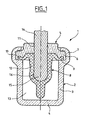
- a thermal cylinder 1 which comprises a cup 2 which has a cylindrical portion 3 and a rear radial portion 4, a radial front cover 5 whose periphery 6 is taken by crimping in a front annular portion 7 of the cup 2, and a seal 8 whose peripheral portion 9 is pinched during said crimping between a rear portion of the peripheral portion 6 of the cover 5 and an annular radial shoulder before 10 of the cup 2.
- the cover 5 has a through axial guide passage 11 and the seal 8 has a portion 12 in the form of a flexible glove finger which is open on the side of the passage 11 so that the seal 8 defines in the cup 2 an opposite chamber 13 to the lid 5 and filled with an expandable product such as wax.
- the cylinder 1 also has a longitudinal cylindrical rod 14 which extends through the passage 11 of the lid 5, in which it is guided longitudinally, this rod being engaged in the glove finger 12 of the gasket 8, the inside of which is lubricated.
- the variations in the volume of the expandable product contained in the chamber 13, due to temperature variations, produce longitudinal displacements of the rod 14 relative to the cup 3 and to the lid 5, by generating sliding of the rod 14 in the glove finger 12 which envelopes and remains in contact with its part extending behind the guide through passage 11, the rod 14 coming out under the effect of the expansion of the expandable product and returning under the effect of an organ outside booster.
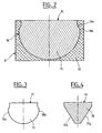
- the rear end portion 15 of the longitudinal rod 14 has a projecting annular portion 16 whose largest diameter is greater than the diameter of the guide through passage 11, of such that the projecting annular portion 16 is able to cooperate with the rear face of the cover 5, around the through passage 11, to prevent the forward extraction of the rod 14 outside the through passage 11.
- the annular projecting portion 16 of the rod 14 has only rounded shapes which comprise, from front to back, a concave portion 16a followed by a convex portion 16b which joins a rear end face 16c of the rod 12 of shape substantially hemispherical.
- the rod 14, generally made of stainless steel can be manufactured by turning, then treated with others by stirring with an abrasive in order to eliminate any asperities which could hinder its sliding in the through passage 11 of the cover 5 and sliding in the thimble 15.
- FIGS. 3 and 4 it can be seen that there is shown an alternative embodiment of the rear end portion 15 of the rod 14, according to which this end portion is stamped so as to form two opposing faces 17a and 17b forming a V and which, by displacement of material, allows the formation of opposed projecting parts 18a and 18b whose longitudinal profiles are similar to the longitudinal profile of the projecting annular portion 16 of the previous example .
- the rod 14 can be treated with others by stirring with an abrasive.
- the present invention is not limited to the example described above.
- the rear portion of the longitudinal rod could extend in a rear recess of the cover extending the guide through passage, the seal cooperating with the rear face of the rod via a sliding ring in this obviously.
- the rod would have a protruding portion capable of bearing against a transition shoulder between the guide through passage and said recess of the cover.
Abstract
Description
La présente invention concerne le domaine des vérins thermiques qui comprennent une coupelle, un couvercle fermant cette coupelle et présentant un passage traversant de guidage, un joint dont le bord périphérique est pris entre la coupelle et le couvercle et qui délimite dans la coupelle une chambre opposée au couvercle et remplie d'un produit dilatable, ainsi qu'une tige qui s'étend au travers dudit passage traversant du couvercle et qui coopère avec ledit joint, de telle sorte que des variations de volume du produit dilatable, sous l'effet de variations de température, produisent des déplacements longitudinaux de ladite tige dans un sens ou dans l'autre.The present invention relates to the field of thermal cylinders which comprise a cup, a lid closing the cup and having a guide through passage, a seal whose peripheral edge is taken between the cup and the lid and which defines in the cup an opposite chamber to the lid and filled with an expandable product, and a rod which extends through said through passage of the lid and which cooperates with said seal, so that variations in the volume of the expandable product, under the effect of variations in temperature, produce longitudinal displacements of said rod in one direction or the other.
De tels vérins thermiques sont utilisés en particulier pour actionner et réguler des clapets, des vannes, des volets, en particulier dans le domaine de l'automobile ou des appareils de chauffage ou de régulation thermique.Such thermal cylinders are used in particular to actuate and regulate valves, valves, shutters, in particular in the field of automotive or heating or temperature control devices.
Actuellement, la tige des vérins est constituée par un barreau cylindrique sans aspérités, ajusté dans le passage traversant du couvercle afin d'obtenir un guidage longitudinal parfait (cf. GB 2 374 143 A). De plus, compte tenu des conditions environnantes d'utilisation de tels vérins, la tige est en acier inoxydable.Currently, the rod of the cylinders is constituted by a cylindrical bar without asperities, adjusted in the through passage of the cover to obtain a perfect longitudinal guide (see GB 2,374,143 A). In addition, given the surrounding conditions of use of such cylinders, the rod is made of stainless steel.
La présente invention vise à améliorer les vérins thermiques existants.The present invention aims to improve the existing thermal cylinders.
Selon la présente invention, ladite tige présente au moins une partie radialement en saillie formée sur sa partie située intérieurement au-delà du passage traversant de guidage dudit couvercle, constituant une butée susceptible de venir coopérer avec le couvercle pour empêcher cette tige d'être extraite à l'extérieur dudit passage traversant.According to the present invention, said rod has at least one radially projecting portion formed on its portion located internally beyond the guide through passage of said lid, constituting an abutment engageable with the lid to prevent this rod from being extracted. outside said through passage.
Selon la présente invention, ladite partie en saillie de ladite tige est de préférence annulaire.According to the present invention, said projecting portion of said rod is preferably annular.
Selon une variante d'exécution de la présente invention, ledit joint présente une partie en forme de doigt de gant ouvert du côté du passage traversant du couvercle, ladite tige présentant une partie d'extrémité qui est engagée dans ce doigt de gant et qui présente ladite partie en saillie.According to an alternative embodiment of the present invention, said seal has an open portion of a glove finger on the side of the through passage of the cover, said rod having an end portion which is engaged in the glove finger and which has said projecting portion.
Selon la présente invention, ladite partie en saillie présente de préférence exclusivement des formes arrondies.According to the present invention, said projecting portion preferably has exclusively rounded shapes.
Selon la présente invention, ladite tige et ledit passage traversant de guidage dudit couvercle sont de préférence de sections circulaires, ladite partie en saillie s'étendant de préférence radialement au-delà du bord de ce passage traversant.According to the present invention, said rod and said through passage for guiding said lid are preferably circular sections, said projecting portion preferably extending radially beyond the edge of this through passage.
La présente invention sera mieux comprise à l'étude d'un vérin thermique décrit à titre d'exemple non limitatif et illustré par le dessin sur lequel :
- la figure 1 représente une coupe longitudinale d'un vérin thermique selon la présente invention ;
- la figure 2 représente une coupe longitudinale agrandie d'une partie intérieure dudit vérin ;
- et les figures 3 et 4 représentent une variante d'exécution de cette partie dudit vérin.
- Figure 1 shows a longitudinal section of a thermal cylinder according to the present invention;
- Figure 2 shows an enlarged longitudinal section of an inner portion of said cylinder;
- and Figures 3 and 4 show an alternative embodiment of this part of said cylinder.
En se reportant à la figure 1, on peut voir qu'on a représenté un vérin thermique 1 qui comprend une coupelle 2 qui présente une partie cylindrique 3 et une partie radiale arrière 4, un couvercle radial avant 5 dont la périphérie 6 est prise par sertissage dans une partie annulaire avant 7 de la coupelle 2, et un joint d'étanchéité 8 dont la partie périphérique 9 est pincée lors dudit sertissage entre une partie arrière de la partie périphérique 6 du couvercle 5 et un épaulement radial annulaire avant 10 de la coupelle 2.Referring to FIG. 1, it can be seen that a
Le couvercle 5 présente un passage axial traversant de guidage 11 et le joint 8 présente une partie 12 en forme de doigt de gant souple qui est ouverte du côté du passage 11 de telle sorte que le joint 8 délimite dans la coupelle 2 une chambre 13 opposée au couvercle 5 et remplie d'un produit dilatable tel que de la cire.The
Le vérin 1 présente en outre une tige longitudinale cylindrique 14 qui s'étend au travers du passage 11 du couvercle 5, dans lequel elle est guidée longitudinalement, cette tige étant engagée dans le doigt de gant 12 du joint 8 dont l'intérieur est lubrifié.The
Ainsi, les variations de volume du produit dilatable contenu dans la chambre 13, dûes à des variations de température, produisent des déplacements longitudinaux de la tige 14 par rapport à la coupelle 3 et au couvercle 5, en engendrant des glissements de la tige 14 dans le doigt de gant 12 qui enveloppe et reste en contact avec sa partie s'étendant en arrière du passage traversant de guidage 11, la tige 14 sortant sous l'effet de la dilatation du produit dilatable et rentrant sous l'effet d'un organe de rappel extérieur.Thus, the variations in the volume of the expandable product contained in the
Comme le montrent la figure 1 et plus précisément la figure 2, la partie d'extrémité arrière 15 de la tige longitudinale 14 présente une partie annulaire en saillie 16 dont le diamètre le plus grand est supérieur au diamètre du passage traversant de guidage 11, de telle sorte que cette partie annulaire en saillie 16 est susceptible de venir coopérer avec la face arrière du couvercle 5, autour du passage traversant 11, pour empêcher l'extraction vers l'avant de la tige 14 à l'extérieur du passage traversant 11.As shown in FIG. 1 and more precisely in FIG. 2, the
La partie annulaire en saillie 16 de la tige 14 présente exclusivement des formes arrondies qui comprennent, d'avant en arrière, une partie concave 16a suivie d'une partie convexe 16b qui rejoint une face d'extrémité arrière 16c de la tige 12 de forme sensiblement hémisphérique.The
Ainsi, lorsque la tige 14 se déplace longitudinalement dans et en contact avec le doigt de gant 12, ce dernier 12 ne rencontre aucune arête qui serait susceptible de l'endommager.Thus, when the
Dans une variante, la tige 14, généralement en acier inoxydable, peut être fabriquée par tournage, puis traitée avec d'autres par brassage avec un abrasif afin de supprimer toutes aspérités qui pourraient nuire à son glissement dans le passage traversant 11 du couvercle 5 et à son glissement dans le doigt de gant 15.In a variant, the
En se reportant aux figures 3 et 4, on peut voir qu'on a représenté une variante d'exécution de la partie d'extrémité arrière 15 de la tige 14, selon laquelle cette partie d'extrémité est matricée de façon à former deux pans opposés 17a et 17b formant un V et qui, par refoulement de matière, permet la formation de parties opposées en saillie 18a et 18b dont les profils longitudinaux s'apparentent au profil longitudinal de la partie annulaire en saillie 16 de l'exemple précédent.Referring to FIGS. 3 and 4, it can be seen that there is shown an alternative embodiment of the
Dans ce cas aussi, la tige 14 peut être traitée avec d'autres par brassage avec un abrasif.In this case too, the
Il résulte de ce qui précède que la tige longitudinale 14, tout en ayant les qualités requises pour un bon fonctionnemnt du vérin 1, ne peut pas s'extraire du passage tranversant 11 du couvercle 5 lors de manipulations du vérin 1, principalement lors des opérations de montage de ce dernier dans un appareillage.It follows from the foregoing that the
La présente invention ne se limite pas à l'exemple ci-dessus décrit.The present invention is not limited to the example described above.
En particulier, la partie arrière de la tige longitudinale pourrait s'étendre dans un évidemment arrière du couvercle prolongeant le passage traversant de guidage, le joint coopérant avec la face arrière de la tige par l'intermédiaire d'une bague coulissant dans cet évidemment. Dans ce cas, la tige présenterait une partie en saillie susceptible de venir en appui contre un épaulement de transition entre le passage traversant de guidage et ledit évidemment du couvercle.In particular, the rear portion of the longitudinal rod could extend in a rear recess of the cover extending the guide through passage, the seal cooperating with the rear face of the rod via a sliding ring in this obviously. In this case, the rod would have a protruding portion capable of bearing against a transition shoulder between the guide through passage and said recess of the cover.
Bien d'autres variantes de réalisation sont possibles sans sortir du cadre défini par les revendications annexées.Many other embodiments are possible without departing from the scope defined by the appended claims.
Claims (5)
- Thermal actuator comprising a cup, a lid closing this cup and exhibiting a guide through-passage, a seal, the peripheral edge of which is sandwiched between the cup and the lid and which within the said cup delimits a chamber on the opposite side to the said lid and filled with an expandable product, and a rod which extends through the through-passage in the lid and collaborates with the said seal, characterized in that the said rod (14) has at least one radially projecting part (16) formed on its part situated internally beyond the guide through-passage (11) in the said lid, constituting a limit stop able to collaborate with the lid to prevent this rod from being extracted from the said through-passage.
- Actuator according to Claim 1, characterized in that the said projecting part (16) of the said rod is annular.
- Actuator according to one of Claims 1 and 2, characterized in that the said seal (8) has a thimble-shaped part (12) open on the side of the through-passage in the lid, the said rod exhibiting an end part (15) which is engaged in this thimble and exhibits the said projecting part (16).
- Actuator according to any one of the preceding claims, characterized in that the said projecting part (16) exhibits exclusively rounded shapes.
- Actuator according to any one of the preceding claims, characterized in that the said rod (14) and the said guide through-passage (11) in the said lid are of circular cross sections, the said projecting part (16) extending radially beyond the edge of this through-passage.
Applications Claiming Priority (2)
| Application Number | Priority Date | Filing Date | Title |
|---|---|---|---|
| FR0310978 | 2003-09-18 | ||
| FR0310978A FR2860050B1 (en) | 2003-09-18 | 2003-09-18 | THERMAL CYLINDER |
Publications (2)
| Publication Number | Publication Date |
|---|---|
| EP1517035A1 EP1517035A1 (en) | 2005-03-23 |
| EP1517035B1 true EP1517035B1 (en) | 2006-04-19 |
Family
ID=34178915
Family Applications (1)
| Application Number | Title | Priority Date | Filing Date |
|---|---|---|---|
| EP04291694A Active EP1517035B1 (en) | 2003-09-18 | 2004-07-05 | Thermal actuator |
Country Status (4)
| Country | Link |
|---|---|
| EP (1) | EP1517035B1 (en) |
| AT (1) | ATE323831T1 (en) |
| DE (1) | DE602004000681T2 (en) |
| FR (1) | FR2860050B1 (en) |
Family Cites Families (5)
| Publication number | Priority date | Publication date | Assignee | Title |
|---|---|---|---|---|
| US3046787A (en) * | 1958-10-06 | 1962-07-31 | Robertshaw Fulton Controls Co | Fusion type thermal element |
| US3793837A (en) * | 1972-08-10 | 1974-02-26 | Controls Co Of America | Wax element diaphragm and seal |
| DE2448065B2 (en) * | 1974-10-09 | 1977-08-04 | Gustav Wähler GmbH u. Co, 7300 Esslingen | THERMOSTATIC ACTUATOR |
| GB2374143A (en) * | 2000-07-26 | 2002-10-09 | Diamond H Controls Ltd | Thermally-responsive actuator with rolling diaphragm |
| DE10104690C2 (en) * | 2001-02-02 | 2003-07-03 | Andreas Moehlenhoff | Method for operating a temperature-dependent control element and temperature-dependent control element |
-
2003
- 2003-09-18 FR FR0310978A patent/FR2860050B1/en not_active Expired - Fee Related
-
2004
- 2004-07-05 DE DE602004000681T patent/DE602004000681T2/en active Active
- 2004-07-05 EP EP04291694A patent/EP1517035B1/en active Active
- 2004-07-05 AT AT04291694T patent/ATE323831T1/en not_active IP Right Cessation
Also Published As
| Publication number | Publication date |
|---|---|
| EP1517035A1 (en) | 2005-03-23 |
| DE602004000681D1 (en) | 2006-05-24 |
| FR2860050B1 (en) | 2005-11-04 |
| FR2860050A1 (en) | 2005-03-25 |
| ATE323831T1 (en) | 2006-05-15 |
| DE602004000681T2 (en) | 2007-04-12 |
Similar Documents
| Publication | Publication Date | Title |
|---|---|---|
| EP0893641A1 (en) | Device for connecting two pipe elements and use of such a pipe element connection device | |
| FR2548321A1 (en) | CYLINDER-PISTON ARRANGEMENT FOR BRAKE, WITH AT LEAST PARTIALLY CERAMIC PISTON | |
| FR2705936A1 (en) | Wiper device comprising an articulation between a crank and a connecting rod. | |
| FR2996787A3 (en) | Spray head assembly for lotion, has cylinder assembly with cylinders, and narrowed part between cylinders, where narrowed part is engaged with sealing part or cavity so as to form watertight state, and valve contacting input of one cylinder | |
| FR2470310A1 (en) | PISTON WITH POSITION DETECTABLE WITHOUT CONTACT | |
| CH660066A5 (en) | ANNULAR SEALING OF CAST IRON PIPES. | |
| FR2671847A1 (en) | FITTINGS HANDLE. | |
| EP0821294B1 (en) | Push-button and method of assembling the same | |
| FR2492034A1 (en) | RADIAL SEAL TRIM | |
| FR2520832A1 (en) | SEALING DEVICE, IN PARTICULAR BETWEEN A PISTON AND ITS ASSOCIATED CYLINDER | |
| EP1517035B1 (en) | Thermal actuator | |
| FR3011760A1 (en) | TARGET INSERT TO BE INCLUDED IN INJECTION MOLDED PART, AND METHOD OF MANUFACTURING SUCH A PART | |
| FR2618867A1 (en) | PISTON EQUIPPED WITH A CYLINDER, ESPECIALLY A PNEUMATIC SPRING | |
| FR2590343A1 (en) | FLUID ACTUATED DEVICE | |
| FR2954421A1 (en) | Housing for component within hydraulic controlled system, particularly master cylinder of clutch- or brake system of vehicle, has housing part and another housing part, in which axially movable piston is supported by actuation of piston rod | |
| FR2465109A1 (en) | Linear actuator assembled by metal deformation - has cylinder made from drawn tube with shoulders retaining sealing and bearing rings and separate base | |
| FR2598189A1 (en) | Fastening element, nut or stud, to be crimped | |
| FR2678027A3 (en) | Cover fastening for pneumatic or hydraulic jack | |
| FR2496820A1 (en) | Low wear hydraulic or pneumatic piston seal - has thin middle section to adapt to cylinder wall spacing | |
| EP0002149A1 (en) | Sealing cup for hydraulic pressure generator | |
| FR2490309A1 (en) | RING SEAL FOR PISTON OR PISTON ROD, ESPECIALLY HIGH PRESSURE HYDRAULIC JACK | |
| FR2705425A1 (en) | Valve stem seal. | |
| CA2401307A1 (en) | Flap accessory | |
| EP1282795A1 (en) | Piston, in particular for sampling valve | |
| EP0719969B1 (en) | Safety valve |
Legal Events
| Date | Code | Title | Description |
|---|---|---|---|
| PUAI | Public reference made under article 153(3) epc to a published international application that has entered the european phase |
Free format text: ORIGINAL CODE: 0009012 |
|
| AK | Designated contracting states |
Kind code of ref document: A1 Designated state(s): AT BE BG CH CY CZ DE DK EE ES FI FR GB GR HU IE IT LI LU MC NL PL PT RO SE SI SK TR |
|
| AX | Request for extension of the european patent |
Extension state: AL HR LT LV MK |
|
| GRAP | Despatch of communication of intention to grant a patent |
Free format text: ORIGINAL CODE: EPIDOSNIGR1 |
|
| 17P | Request for examination filed |
Effective date: 20050826 |
|
| AKX | Designation fees paid |
Designated state(s): AT BE BG CH CY CZ DE DK EE ES FI FR GB GR HU IE IT LI LU MC NL PL PT RO SE SI SK TR |
|
| GRAS | Grant fee paid |
Free format text: ORIGINAL CODE: EPIDOSNIGR3 |
|
| GRAA | (expected) grant |
Free format text: ORIGINAL CODE: 0009210 |
|
| AK | Designated contracting states |
Kind code of ref document: B1 Designated state(s): AT BE BG CH CY CZ DE DK EE ES FI FR GB GR HU IE IT LI LU MC NL PL PT RO SE SI SK TR |
|
| PG25 | Lapsed in a contracting state [announced via postgrant information from national office to epo] |
Ref country code: SI Free format text: LAPSE BECAUSE OF FAILURE TO SUBMIT A TRANSLATION OF THE DESCRIPTION OR TO PAY THE FEE WITHIN THE PRESCRIBED TIME-LIMIT Effective date: 20060419 Ref country code: PL Free format text: LAPSE BECAUSE OF FAILURE TO SUBMIT A TRANSLATION OF THE DESCRIPTION OR TO PAY THE FEE WITHIN THE PRESCRIBED TIME-LIMIT Effective date: 20060419 Ref country code: CZ Free format text: LAPSE BECAUSE OF FAILURE TO SUBMIT A TRANSLATION OF THE DESCRIPTION OR TO PAY THE FEE WITHIN THE PRESCRIBED TIME-LIMIT Effective date: 20060419 Ref country code: AT Free format text: LAPSE BECAUSE OF FAILURE TO SUBMIT A TRANSLATION OF THE DESCRIPTION OR TO PAY THE FEE WITHIN THE PRESCRIBED TIME-LIMIT Effective date: 20060419 Ref country code: SK Free format text: LAPSE BECAUSE OF FAILURE TO SUBMIT A TRANSLATION OF THE DESCRIPTION OR TO PAY THE FEE WITHIN THE PRESCRIBED TIME-LIMIT Effective date: 20060419 Ref country code: IE Free format text: LAPSE BECAUSE OF FAILURE TO SUBMIT A TRANSLATION OF THE DESCRIPTION OR TO PAY THE FEE WITHIN THE PRESCRIBED TIME-LIMIT Effective date: 20060419 Ref country code: FI Free format text: LAPSE BECAUSE OF FAILURE TO SUBMIT A TRANSLATION OF THE DESCRIPTION OR TO PAY THE FEE WITHIN THE PRESCRIBED TIME-LIMIT Effective date: 20060419 Ref country code: NL Free format text: LAPSE BECAUSE OF FAILURE TO SUBMIT A TRANSLATION OF THE DESCRIPTION OR TO PAY THE FEE WITHIN THE PRESCRIBED TIME-LIMIT Effective date: 20060419 Ref country code: RO Free format text: LAPSE BECAUSE OF FAILURE TO SUBMIT A TRANSLATION OF THE DESCRIPTION OR TO PAY THE FEE WITHIN THE PRESCRIBED TIME-LIMIT Effective date: 20060419 |
|
| REG | Reference to a national code |
Ref country code: GB Ref legal event code: FG4D Free format text: NOT ENGLISH |
|
| REF | Corresponds to: |
Ref document number: 602004000681 Country of ref document: DE Date of ref document: 20060524 Kind code of ref document: P |
|
| REG | Reference to a national code |
Ref country code: IE Ref legal event code: FG4D Free format text: LANGUAGE OF EP DOCUMENT: FRENCH |
|
| GBT | Gb: translation of ep patent filed (gb section 77(6)(a)/1977) |
Effective date: 20060621 |
|
| PG25 | Lapsed in a contracting state [announced via postgrant information from national office to epo] |
Ref country code: SE Free format text: LAPSE BECAUSE OF FAILURE TO SUBMIT A TRANSLATION OF THE DESCRIPTION OR TO PAY THE FEE WITHIN THE PRESCRIBED TIME-LIMIT Effective date: 20060719 Ref country code: DK Free format text: LAPSE BECAUSE OF FAILURE TO SUBMIT A TRANSLATION OF THE DESCRIPTION OR TO PAY THE FEE WITHIN THE PRESCRIBED TIME-LIMIT Effective date: 20060719 |
|
| REG | Reference to a national code |
Ref country code: HU Ref legal event code: AG4A Ref document number: E000439 Country of ref document: HU |
|
| PG25 | Lapsed in a contracting state [announced via postgrant information from national office to epo] |
Ref country code: ES Free format text: LAPSE BECAUSE OF FAILURE TO SUBMIT A TRANSLATION OF THE DESCRIPTION OR TO PAY THE FEE WITHIN THE PRESCRIBED TIME-LIMIT Effective date: 20060730 |
|
| PG25 | Lapsed in a contracting state [announced via postgrant information from national office to epo] |
Ref country code: MC Free format text: LAPSE BECAUSE OF NON-PAYMENT OF DUE FEES Effective date: 20060731 |
|
| PG25 | Lapsed in a contracting state [announced via postgrant information from national office to epo] |
Ref country code: PT Free format text: LAPSE BECAUSE OF FAILURE TO SUBMIT A TRANSLATION OF THE DESCRIPTION OR TO PAY THE FEE WITHIN THE PRESCRIBED TIME-LIMIT Effective date: 20060919 |
|
| NLV1 | Nl: lapsed or annulled due to failure to fulfill the requirements of art. 29p and 29m of the patents act | ||
| REG | Reference to a national code |
Ref country code: IE Ref legal event code: FD4D |
|
| PGFP | Annual fee paid to national office [announced via postgrant information from national office to epo] |
Ref country code: BE Payment date: 20061218 Year of fee payment: 3 |
|
| PLBE | No opposition filed within time limit |
Free format text: ORIGINAL CODE: 0009261 |
|
| STAA | Information on the status of an ep patent application or granted ep patent |
Free format text: STATUS: NO OPPOSITION FILED WITHIN TIME LIMIT |
|
| 26N | No opposition filed |
Effective date: 20070122 |
|
| BERE | Be: lapsed |
Owner name: DAUPHINOISE THOMSON SAS Effective date: 20070731 |
|
| PG25 | Lapsed in a contracting state [announced via postgrant information from national office to epo] |
Ref country code: GR Free format text: LAPSE BECAUSE OF FAILURE TO SUBMIT A TRANSLATION OF THE DESCRIPTION OR TO PAY THE FEE WITHIN THE PRESCRIBED TIME-LIMIT Effective date: 20060720 |
|
| PG25 | Lapsed in a contracting state [announced via postgrant information from national office to epo] |
Ref country code: EE Free format text: LAPSE BECAUSE OF FAILURE TO SUBMIT A TRANSLATION OF THE DESCRIPTION OR TO PAY THE FEE WITHIN THE PRESCRIBED TIME-LIMIT Effective date: 20060419 Ref country code: BG Free format text: LAPSE BECAUSE OF FAILURE TO SUBMIT A TRANSLATION OF THE DESCRIPTION OR TO PAY THE FEE WITHIN THE PRESCRIBED TIME-LIMIT Effective date: 20060719 |
|
| PG25 | Lapsed in a contracting state [announced via postgrant information from national office to epo] |
Ref country code: LU Free format text: LAPSE BECAUSE OF NON-PAYMENT OF DUE FEES Effective date: 20060705 Ref country code: TR Free format text: LAPSE BECAUSE OF FAILURE TO SUBMIT A TRANSLATION OF THE DESCRIPTION OR TO PAY THE FEE WITHIN THE PRESCRIBED TIME-LIMIT Effective date: 20060419 |
|
| PG25 | Lapsed in a contracting state [announced via postgrant information from national office to epo] |
Ref country code: BE Free format text: LAPSE BECAUSE OF NON-PAYMENT OF DUE FEES Effective date: 20070731 |
|
| PG25 | Lapsed in a contracting state [announced via postgrant information from national office to epo] |
Ref country code: CY Free format text: LAPSE BECAUSE OF FAILURE TO SUBMIT A TRANSLATION OF THE DESCRIPTION OR TO PAY THE FEE WITHIN THE PRESCRIBED TIME-LIMIT Effective date: 20060419 |
|
| REG | Reference to a national code |
Ref country code: CH Ref legal event code: PL |
|
| PG25 | Lapsed in a contracting state [announced via postgrant information from national office to epo] |
Ref country code: LI Free format text: LAPSE BECAUSE OF NON-PAYMENT OF DUE FEES Effective date: 20080731 Ref country code: CH Free format text: LAPSE BECAUSE OF NON-PAYMENT OF DUE FEES Effective date: 20080731 |
|
| REG | Reference to a national code |
Ref country code: DE Ref legal event code: R082 Ref document number: 602004000681 Country of ref document: DE Representative=s name: MEISSNER, BOLTE & PARTNER GBR, DE Ref country code: DE Ref legal event code: R082 Ref document number: 602004000681 Country of ref document: DE Representative=s name: MEISSNER BOLTE PATENTANWAELTE RECHTSANWAELTE P, DE |
|
| REG | Reference to a national code |
Ref country code: DE Ref legal event code: R082 Ref document number: 602004000681 Country of ref document: DE Representative=s name: MEISSNER, BOLTE & PARTNER GBR, DE |
|
| REG | Reference to a national code |
Ref country code: FR Ref legal event code: PLFP Year of fee payment: 13 |
|
| REG | Reference to a national code |
Ref country code: FR Ref legal event code: PLFP Year of fee payment: 14 |
|
| REG | Reference to a national code |
Ref country code: FR Ref legal event code: PLFP Year of fee payment: 15 |
|
| PGFP | Annual fee paid to national office [announced via postgrant information from national office to epo] |
Ref country code: FR Payment date: 20230424 Year of fee payment: 20 |
|
| PGFP | Annual fee paid to national office [announced via postgrant information from national office to epo] |
Ref country code: IT Payment date: 20230707 Year of fee payment: 20 Ref country code: GB Payment date: 20230725 Year of fee payment: 20 |
|
| PGFP | Annual fee paid to national office [announced via postgrant information from national office to epo] |
Ref country code: HU Payment date: 20230622 Year of fee payment: 20 Ref country code: DE Payment date: 20230712 Year of fee payment: 20 |