EP1517018A1 - Agencement de moteur comprenant un alternateur. - Google Patents
Agencement de moteur comprenant un alternateur. Download PDFInfo
- Publication number
- EP1517018A1 EP1517018A1 EP04300588A EP04300588A EP1517018A1 EP 1517018 A1 EP1517018 A1 EP 1517018A1 EP 04300588 A EP04300588 A EP 04300588A EP 04300588 A EP04300588 A EP 04300588A EP 1517018 A1 EP1517018 A1 EP 1517018A1
- Authority
- EP
- European Patent Office
- Prior art keywords
- alternator
- housing
- distribution
- cylinder block
- atria
- Prior art date
- Legal status (The legal status is an assumption and is not a legal conclusion. Google has not performed a legal analysis and makes no representation as to the accuracy of the status listed.)
- Granted
Links
- 210000002837 heart atrium Anatomy 0.000 claims abstract description 7
- 238000006073 displacement reaction Methods 0.000 abstract 1
- 238000007789 sealing Methods 0.000 abstract 1
- 230000007423 decrease Effects 0.000 description 2
- 239000012634 fragment Substances 0.000 description 2
- 229910001018 Cast iron Inorganic materials 0.000 description 1
- XAGFODPZIPBFFR-UHFFFAOYSA-N aluminium Chemical group [Al] XAGFODPZIPBFFR-UHFFFAOYSA-N 0.000 description 1
- 229910052782 aluminium Inorganic materials 0.000 description 1
- 230000002596 correlated effect Effects 0.000 description 1
Images

Classifications
-
- F—MECHANICAL ENGINEERING; LIGHTING; HEATING; WEAPONS; BLASTING
- F02—COMBUSTION ENGINES; HOT-GAS OR COMBUSTION-PRODUCT ENGINE PLANTS
- F02B—INTERNAL-COMBUSTION PISTON ENGINES; COMBUSTION ENGINES IN GENERAL
- F02B67/00—Engines characterised by the arrangement of auxiliary apparatus not being otherwise provided for, e.g. the apparatus having different functions; Driving auxiliary apparatus from engines, not otherwise provided for
-
- F—MECHANICAL ENGINEERING; LIGHTING; HEATING; WEAPONS; BLASTING
- F02—COMBUSTION ENGINES; HOT-GAS OR COMBUSTION-PRODUCT ENGINE PLANTS
- F02B—INTERNAL-COMBUSTION PISTON ENGINES; COMBUSTION ENGINES IN GENERAL
- F02B63/00—Adaptations of engines for driving pumps, hand-held tools or electric generators; Portable combinations of engines with engine-driven devices
- F02B63/04—Adaptations of engines for driving pumps, hand-held tools or electric generators; Portable combinations of engines with engine-driven devices for electric generators
-
- F—MECHANICAL ENGINEERING; LIGHTING; HEATING; WEAPONS; BLASTING
- F02—COMBUSTION ENGINES; HOT-GAS OR COMBUSTION-PRODUCT ENGINE PLANTS
- F02B—INTERNAL-COMBUSTION PISTON ENGINES; COMBUSTION ENGINES IN GENERAL
- F02B77/00—Component parts, details or accessories, not otherwise provided for
- F02B77/14—Engine-driven auxiliary devices combined into units
-
- F—MECHANICAL ENGINEERING; LIGHTING; HEATING; WEAPONS; BLASTING
- F02—COMBUSTION ENGINES; HOT-GAS OR COMBUSTION-PRODUCT ENGINE PLANTS
- F02F—CYLINDERS, PISTONS OR CASINGS, FOR COMBUSTION ENGINES; ARRANGEMENTS OF SEALINGS IN COMBUSTION ENGINES
- F02F7/00—Casings, e.g. crankcases
- F02F7/0065—Shape of casings for other machine parts and purposes, e.g. utilisation purposes, safety
- F02F7/0073—Adaptations for fitting the engine, e.g. front-plates or bell-housings
-
- F—MECHANICAL ENGINEERING; LIGHTING; HEATING; WEAPONS; BLASTING
- F02—COMBUSTION ENGINES; HOT-GAS OR COMBUSTION-PRODUCT ENGINE PLANTS
- F02B—INTERNAL-COMBUSTION PISTON ENGINES; COMBUSTION ENGINES IN GENERAL
- F02B63/00—Adaptations of engines for driving pumps, hand-held tools or electric generators; Portable combinations of engines with engine-driven devices
- F02B63/04—Adaptations of engines for driving pumps, hand-held tools or electric generators; Portable combinations of engines with engine-driven devices for electric generators
- F02B63/042—Rotating electric generators
Definitions
- the subject of this invention is a motor arrangement comprising inter alia a alternator.
- a permanent search in the automobile is to reduce the clutter of the equipment as engine and related equipment.
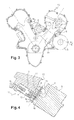
- a housing of distribution 1 substantially shaped lid is placed on the cylinder cover 2 to delimit with it a housing 3 sheltering elements of distribution 4.
- the alternator has the reference 5, the auricles reference 6, the crankcase lug 2 reference 7 and bolt reference 8.
- Housing 3 must have a width sufficient to contain the distribution elements 4.
- the timing case 1 must have what is called a sidewalk 9, that is to say a bearing portion on the cylinder housing 2, of sufficient width. As housing 4 extends to the tab 7, the sidewalk 9 overflows on this one and comes close to one of the atria 6. The possibilities of moving the alternator 5 against the engine are therefore limited.
- the invention is perfected by this it avoids the technical difficulty mentioned above.
- a motor arrangement comprising a cylinder block, a timing case, the cylinder block and the distribution casing together forming a housing of distribution elements, and an alternator attached to the cylinder block, characterized in that the alternator is also attached to the crankcase distribution.
- the housing of distribution 11 now includes, besides a cover 13, a relatively tall edge 14 of height extending to a junction plane at the crankcase cylinders 12 about halfway up the housing 3, which remains unchanged. As a result, the crankcase cylinders 12 is shorter.
- the atria 6 of the alternator 5 now surround a paw fragment 15 belonging to the cylinder block 12, but also a fragment of lug 16 belonging to the housing of distribution 11 and more precisely on board.
- sidewalk 17 between the casings 11 and 12 extends therefore, near the alternator 5, in the leg 7, which allows to perform a redan 18 in the lid 13 and approach the alternator 5 of the engine.
- the very slight reduction in housing volume 3 as a result of the approach of one of the atria 6 is not to be feared in a region where it is empty.
- the increase in volume of the timing case 11 correlated to a decrease in the volume of the cylinder housing 12 decreases advantageously the total mass of the engine, since the first is aluminum and the second cast iron.
Landscapes
- Engineering & Computer Science (AREA)
- Chemical & Material Sciences (AREA)
- Combustion & Propulsion (AREA)
- Mechanical Engineering (AREA)
- General Engineering & Computer Science (AREA)
- Cylinder Crankcases Of Internal Combustion Engines (AREA)
- Motor Or Generator Frames (AREA)
Abstract
Description
Claims (3)
- Agencement de moteur comprenant un carter de cylindres (12), un carter de distribution (11), le carter de cylindres et le carter de distribution forment ensemble un logement (3) d'éléments de distribution (4), et un alternateur (5) attaché au carter de cylindres, caractérisé en ce que l'alternateur est aussi attaché au carter de distribution.
- Agencement selon la revendication 1, caractérisé en ce que le carter de distribution et le carter de cylindres forment ensemble une patte (7 : 15, 16) qui est traversée par une vis traversant aussi des oreillettes (6) de l'alternateur (5) entre lesquelles la patte est disposée.
- Agencement selon l'une quelconque des revendications 1 ou 2, caractérisé en ce que le carter de distribution et le carter de cylindres se joignent par un plan s'étendant sensiblement à mi-profondeur du logement.
Applications Claiming Priority (2)
| Application Number | Priority Date | Filing Date | Title |
|---|---|---|---|
| FR0350568A FR2860038B1 (fr) | 2003-09-18 | 2003-09-18 | Agencement de moteur comprenant un alternateur |
| FR0350568 | 2003-09-18 |
Publications (2)
| Publication Number | Publication Date |
|---|---|
| EP1517018A1 true EP1517018A1 (fr) | 2005-03-23 |
| EP1517018B1 EP1517018B1 (fr) | 2006-11-02 |
Family
ID=34179003
Family Applications (1)
| Application Number | Title | Priority Date | Filing Date |
|---|---|---|---|
| EP20040300588 Expired - Lifetime EP1517018B1 (fr) | 2003-09-18 | 2004-09-10 | Agencement de moteur comprenant un alternateur. |
Country Status (3)
| Country | Link |
|---|---|
| EP (1) | EP1517018B1 (fr) |
| DE (1) | DE602004003006T2 (fr) |
| FR (1) | FR2860038B1 (fr) |
Citations (6)
| Publication number | Priority date | Publication date | Assignee | Title |
|---|---|---|---|---|
| FR515538A (fr) * | 1919-10-07 | 1921-04-02 | Herbert Merton | Perfectionnements apportés à la construction du dispositif servant à régler le mécanisme dans les moteurs à combustion interne |
| GB186518A (en) * | 1921-09-19 | 1922-10-05 | Wolseley Motors Ltd | Improvements in internal combustion engines |
| US4257370A (en) * | 1978-12-29 | 1981-03-24 | Cummins Engine Company, Inc. | Combined gear cover and mount for an internal combustion engine |
| DE19732370A1 (de) * | 1997-07-28 | 1999-02-04 | Volkswagen Ag | Nebenaggregatemodul für eine Brennkraftmaschine |
| EP1258615A2 (fr) * | 2001-05-17 | 2002-11-20 | Honda Giken Kogyo Kabushiki Kaisha | Dispositif d'une culasse |
| EP1283329A2 (fr) * | 2001-08-10 | 2003-02-12 | Adam Opel Ag | Moteur à combustion interne avec courroie dentée couverte pour un arbre à cames |
-
2003
- 2003-09-18 FR FR0350568A patent/FR2860038B1/fr not_active Expired - Fee Related
-
2004
- 2004-09-10 DE DE200460003006 patent/DE602004003006T2/de not_active Expired - Lifetime
- 2004-09-10 EP EP20040300588 patent/EP1517018B1/fr not_active Expired - Lifetime
Patent Citations (6)
| Publication number | Priority date | Publication date | Assignee | Title |
|---|---|---|---|---|
| FR515538A (fr) * | 1919-10-07 | 1921-04-02 | Herbert Merton | Perfectionnements apportés à la construction du dispositif servant à régler le mécanisme dans les moteurs à combustion interne |
| GB186518A (en) * | 1921-09-19 | 1922-10-05 | Wolseley Motors Ltd | Improvements in internal combustion engines |
| US4257370A (en) * | 1978-12-29 | 1981-03-24 | Cummins Engine Company, Inc. | Combined gear cover and mount for an internal combustion engine |
| DE19732370A1 (de) * | 1997-07-28 | 1999-02-04 | Volkswagen Ag | Nebenaggregatemodul für eine Brennkraftmaschine |
| EP1258615A2 (fr) * | 2001-05-17 | 2002-11-20 | Honda Giken Kogyo Kabushiki Kaisha | Dispositif d'une culasse |
| EP1283329A2 (fr) * | 2001-08-10 | 2003-02-12 | Adam Opel Ag | Moteur à combustion interne avec courroie dentée couverte pour un arbre à cames |
Also Published As
| Publication number | Publication date |
|---|---|
| FR2860038B1 (fr) | 2006-02-24 |
| EP1517018B1 (fr) | 2006-11-02 |
| DE602004003006D1 (de) | 2006-12-14 |
| FR2860038A1 (fr) | 2005-03-25 |
| DE602004003006T2 (de) | 2007-05-16 |
Similar Documents
| Publication | Publication Date | Title |
|---|---|---|
| KR100560013B1 (ko) | 내연 기관 및 내연 기관의 일체형 캠 브라켓 | |
| BR9707653A (pt) | Dispositivo para separação de impurezas de óleo lubrificante de um motor de combustão interna | |
| US6591930B2 (en) | Valve cover | |
| US6701884B2 (en) | Cam end cover and gasket assembly | |
| WO2010052401A1 (fr) | Charniere de capot pour vehicule automobile et vehicule comportant une telle charniere de capot | |
| EP1517018A1 (fr) | Agencement de moteur comprenant un alternateur. | |
| FR2957025A1 (fr) | Dispositif de support et de fixation d'un moteur sur le chassis d'un vehicule | |
| EP1482157B1 (fr) | Bâtiment-moteur inférieur | |
| FR2755180A1 (fr) | Dispositif de reniflard pour le carter de vilebrequin d'un moteur a combustion interne | |
| CA2246848A1 (fr) | Moteur a quatre temps pour moteur hors bord | |
| EP2497936A1 (fr) | Conduit d'admission d'air multifonction pour moteur diesel | |
| JPH0410365Y2 (fr) | ||
| FR2956442A1 (fr) | Culasse a structure compacte pour moteur a combustion interne de vehicule | |
| EP3094832B1 (fr) | Moteur à explosion comportant des augets de graissage des cames | |
| JPH11240341A (ja) | 車両用スラント型内燃機関のマウント装置 | |
| EP1876347B1 (fr) | Ensemble comportant des pièces à etancher et un joint métallique avec une partie de liaison frangible et moteur comportant un tel ensemble | |
| FR2662471A1 (fr) | Procede de realisation de puits de bougie dans une culasse d'un moteur a combustion interne et ensemble d'elements destine a former au moins un tel puits de bougie. | |
| US20070240669A1 (en) | Cylinder Crankcase Comprising a Cylinder Liner | |
| FR2699597A1 (fr) | Radiateur à eau refroidi à l'air pour moteur à combustion interne. | |
| JPS5916523Y2 (ja) | エンジンの吸気装置 | |
| KR970044180A (ko) | 자동차의 엔진 오일팬 | |
| FR2895459A1 (fr) | Couvre culasse d'un bloc moteur comportant interieurement une chambre de pre-decantation, une chambre de decantation et un conduit de raccordement des deux chambres | |
| KR19980040146U (ko) | 자동차용 오일 팬의 드레인 플러그 구조 | |
| FR2534319A1 (fr) | Distributeur d'allumage pour moteurs a combustion interne | |
| EP1674676A3 (fr) | Agencement de pompe à huile |
Legal Events
| Date | Code | Title | Description |
|---|---|---|---|
| PUAI | Public reference made under article 153(3) epc to a published international application that has entered the european phase |
Free format text: ORIGINAL CODE: 0009012 |
|
| AK | Designated contracting states |
Kind code of ref document: A1 Designated state(s): AT BE BG CH CY CZ DE DK EE ES FI FR GB GR HU IE IT LI LU MC NL PL PT RO SE SI SK TR |
|
| AX | Request for extension of the european patent |
Extension state: AL HR LT LV MK |
|
| 17P | Request for examination filed |
Effective date: 20050922 |
|
| AKX | Designation fees paid |
Designated state(s): AT BE BG CH CY CZ DE DK EE ES FI FR GB GR HU IE IT LI LU MC NL PL PT RO SE SI SK TR |
|
| GRAP | Despatch of communication of intention to grant a patent |
Free format text: ORIGINAL CODE: EPIDOSNIGR1 |
|
| GRAS | Grant fee paid |
Free format text: ORIGINAL CODE: EPIDOSNIGR3 |
|
| GRAA | (expected) grant |
Free format text: ORIGINAL CODE: 0009210 |
|
| AK | Designated contracting states |
Kind code of ref document: B1 Designated state(s): BE DE ES GB IT |
|
| PG25 | Lapsed in a contracting state [announced via postgrant information from national office to epo] |
Ref country code: IT Free format text: LAPSE BECAUSE OF FAILURE TO SUBMIT A TRANSLATION OF THE DESCRIPTION OR TO PAY THE FEE WITHIN THE PRESCRIBED TIME-LIMIT;WARNING: LAPSES OF ITALIAN PATENTS WITH EFFECTIVE DATE BEFORE 2007 MAY HAVE OCCURRED AT ANY TIME BEFORE 2007. THE CORRECT EFFECTIVE DATE MAY BE DIFFERENT FROM THE ONE RECORDED. Effective date: 20061102 |
|
| REG | Reference to a national code |
Ref country code: GB Ref legal event code: FG4D Free format text: NOT ENGLISH |
|
| REF | Corresponds to: |
Ref document number: 602004003006 Country of ref document: DE Date of ref document: 20061214 Kind code of ref document: P |
|
| PG25 | Lapsed in a contracting state [announced via postgrant information from national office to epo] |
Ref country code: ES Free format text: LAPSE BECAUSE OF FAILURE TO SUBMIT A TRANSLATION OF THE DESCRIPTION OR TO PAY THE FEE WITHIN THE PRESCRIBED TIME-LIMIT Effective date: 20070213 |
|
| GBT | Gb: translation of ep patent filed (gb section 77(6)(a)/1977) |
Effective date: 20070212 |
|
| PLBE | No opposition filed within time limit |
Free format text: ORIGINAL CODE: 0009261 |
|
| STAA | Information on the status of an ep patent application or granted ep patent |
Free format text: STATUS: NO OPPOSITION FILED WITHIN TIME LIMIT |
|
| 26N | No opposition filed |
Effective date: 20070803 |
|
| BERE | Be: lapsed |
Owner name: RENAULT S.A.S. Effective date: 20070930 |
|
| PG25 | Lapsed in a contracting state [announced via postgrant information from national office to epo] |
Ref country code: BE Free format text: LAPSE BECAUSE OF NON-PAYMENT OF DUE FEES Effective date: 20070930 |
|
| PGFP | Annual fee paid to national office [announced via postgrant information from national office to epo] |
Ref country code: GB Payment date: 20150917 Year of fee payment: 12 Ref country code: DE Payment date: 20150922 Year of fee payment: 12 |
|
| REG | Reference to a national code |
Ref country code: DE Ref legal event code: R119 Ref document number: 602004003006 Country of ref document: DE |
|
| GBPC | Gb: european patent ceased through non-payment of renewal fee |
Effective date: 20160910 |
|
| PG25 | Lapsed in a contracting state [announced via postgrant information from national office to epo] |
Ref country code: DE Free format text: LAPSE BECAUSE OF NON-PAYMENT OF DUE FEES Effective date: 20170401 Ref country code: GB Free format text: LAPSE BECAUSE OF NON-PAYMENT OF DUE FEES Effective date: 20160910 |