EP1517007A2 - Elektrischer Fernauslösemechanismus und Verfahren zum Abschalten einer Dampfturbine - Google Patents
Elektrischer Fernauslösemechanismus und Verfahren zum Abschalten einer Dampfturbine Download PDFInfo
- Publication number
- EP1517007A2 EP1517007A2 EP04255577A EP04255577A EP1517007A2 EP 1517007 A2 EP1517007 A2 EP 1517007A2 EP 04255577 A EP04255577 A EP 04255577A EP 04255577 A EP04255577 A EP 04255577A EP 1517007 A2 EP1517007 A2 EP 1517007A2
- Authority
- EP
- European Patent Office
- Prior art keywords
- rod
- trip
- latch
- movement
- trip rod
- Prior art date
- Legal status (The legal status is an assumption and is not a legal conclusion. Google has not performed a legal analysis and makes no representation as to the accuracy of the status listed.)
- Withdrawn
Links
Images
Classifications
-
- F—MECHANICAL ENGINEERING; LIGHTING; HEATING; WEAPONS; BLASTING
- F16—ENGINEERING ELEMENTS AND UNITS; GENERAL MEASURES FOR PRODUCING AND MAINTAINING EFFECTIVE FUNCTIONING OF MACHINES OR INSTALLATIONS; THERMAL INSULATION IN GENERAL
- F16K—VALVES; TAPS; COCKS; ACTUATING-FLOATS; DEVICES FOR VENTING OR AERATING
- F16K31/00—Actuating devices; Operating means; Releasing devices
- F16K31/44—Mechanical actuating means
- F16K31/56—Mechanical actuating means without stable intermediate position, e.g. with snap action
-
- F—MECHANICAL ENGINEERING; LIGHTING; HEATING; WEAPONS; BLASTING
- F01—MACHINES OR ENGINES IN GENERAL; ENGINE PLANTS IN GENERAL; STEAM ENGINES
- F01D—NON-POSITIVE DISPLACEMENT MACHINES OR ENGINES, e.g. STEAM TURBINES
- F01D17/00—Regulating or controlling by varying flow
- F01D17/20—Devices dealing with sensing elements or final actuators or transmitting means between them, e.g. power-assisted
- F01D17/22—Devices dealing with sensing elements or final actuators or transmitting means between them, e.g. power-assisted the operation or power assistance being predominantly non-mechanical
- F01D17/24—Devices dealing with sensing elements or final actuators or transmitting means between them, e.g. power-assisted the operation or power assistance being predominantly non-mechanical electrical
-
- F—MECHANICAL ENGINEERING; LIGHTING; HEATING; WEAPONS; BLASTING
- F01—MACHINES OR ENGINES IN GENERAL; ENGINE PLANTS IN GENERAL; STEAM ENGINES
- F01D—NON-POSITIVE DISPLACEMENT MACHINES OR ENGINES, e.g. STEAM TURBINES
- F01D21/00—Shutting-down of machines or engines, e.g. in emergency; Regulating, controlling, or safety means not otherwise provided for
- F01D21/16—Trip gear
-
- F—MECHANICAL ENGINEERING; LIGHTING; HEATING; WEAPONS; BLASTING
- F05—INDEXING SCHEMES RELATING TO ENGINES OR PUMPS IN VARIOUS SUBCLASSES OF CLASSES F01-F04
- F05D—INDEXING SCHEME FOR ASPECTS RELATING TO NON-POSITIVE-DISPLACEMENT MACHINES OR ENGINES, GAS-TURBINES OR JET-PROPULSION PLANTS
- F05D2220/00—Application
- F05D2220/30—Application in turbines
-
- F—MECHANICAL ENGINEERING; LIGHTING; HEATING; WEAPONS; BLASTING
- F05—INDEXING SCHEMES RELATING TO ENGINES OR PUMPS IN VARIOUS SUBCLASSES OF CLASSES F01-F04
- F05D—INDEXING SCHEME FOR ASPECTS RELATING TO NON-POSITIVE-DISPLACEMENT MACHINES OR ENGINES, GAS-TURBINES OR JET-PROPULSION PLANTS
- F05D2260/00—Function
- F05D2260/50—Kinematic linkage, i.e. transmission of position
- F05D2260/52—Kinematic linkage, i.e. transmission of position involving springs
-
- F—MECHANICAL ENGINEERING; LIGHTING; HEATING; WEAPONS; BLASTING
- F05—INDEXING SCHEMES RELATING TO ENGINES OR PUMPS IN VARIOUS SUBCLASSES OF CLASSES F01-F04
- F05D—INDEXING SCHEME FOR ASPECTS RELATING TO NON-POSITIVE-DISPLACEMENT MACHINES OR ENGINES, GAS-TURBINES OR JET-PROPULSION PLANTS
- F05D2270/00—Control
- F05D2270/01—Purpose of the control system
- F05D2270/02—Purpose of the control system to control rotational speed (n)
- F05D2270/021—Purpose of the control system to control rotational speed (n) to prevent overspeed
Definitions
- This invention relates to a trip mechanism for performing a mechanical function, and, more particularly, to a trip mechanism that is electrically operated and functions to control a device from a remote location, such as shutting down a steam turbine.
- the present invention improves over these prior techniques by providing a remote trip mechanism that can be actuated electrically without the need for pressurized oil, pressurized air, or the like.
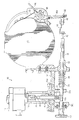
- the drawing is a sectional view of an embodiment of the present invention.
- the reference 10 refers, in general, to an electrically operated remote trip mechanism according to an embodiment of the invention.
- the mechanism includes a solenoid 12 having a plunger 12a that reciprocates in a housing.
- the plunger 12a is normally fully extended from the housing of the solenoid 12 but moves in an axial direction upwardly towards the housing in response to the application of an electrical signal to the solenoid, which can be done remotely or by switch associated with the solenoid, all in a conventional manner.
- the solenoid 12 is supported in one end portion of a hollow cylindrical adapter 14 in any conventional manner such as a threaded engagement.
- a flange 14a is formed on the other end of the adapter and is bolted to a support bracket 16.
- the adapter 14 houses a portion of a latch rod 18 that is connected at one end to the plunger 12a by a jam nut 20. The other end portion of the latch rod 18 projects outwardly from the adapter 14.
- a spring 24 is supported on a stepped-down portion of that portion of the latch rod 18 extending out from the adapter 14 and the upper end of the spring rests against an adjuster member 26 that extends around the latch rod 18 and through an opening in the support bracket 16.
- the adjuster member 26 is in threaded engagement with the support bracket 16 so that rotation of the member 26 causes it to move axially and adjust the compression of the spring 24.
- the other end of the spring 24 rests on a head 18a formed on, or attached to, the latter end of the latch rod 18 so that the spring normally urges the head, and therefore the latch rod, in a downwardly direction, as viewed in the drawing.
- a trip rod 30 extends perpendicular to the latch rod 18 and through an adjuster nut 32 supported in a threaded opening in the bracket 16.
- the adjuster nut 32 is fixed to the trip rod 30 so that rotation of the nut causes it, and the trip rod, to move axially.
- a spring 34 extends around a portion of the trip rod 30 and between the nut 32 and an annular spring seat 36 also extending around the trip rod and secured thereto. Therefore, the above axial movement of the adjuster nut 32 and the trip rod 30 adjusts the compression of the spring 34.
- the compressed spring 34 urges the spring seat 36, and therefore the trip rod 30, in a direction from right-to-left, as viewed in the drawing.
- the trip rod 30 extends through openings in a guide 38a and a bushing 38b, respectively, that extend from the bracket 16 and are spaced to either side of the latch rod 18.
- the guide 38a and the bushing 38b support the trip rod 30 in a position in which it is engagable by the head 18a of the latch rod.
- a reset knob 40 is fixed over the end of the trip rod 30 adjacent the bushing 38b, and an adjustable bolt 42 extends from the other end of the trip rod 30 for receiving one end portion of a latch 44.
- An overspeed safety device 45 is mounted to the bracket 16 and is not shown in detail since it forms no part of the present invention.
- a trip lever 46 is mounted for rotation on the overspeed safety device 45 and includes two legs 46a and 46b that extend from a hub 46c at an angle to each other. The other end portion of the latch 44 is bolted to a flange 48 that extends from the end portion of the leg 46a.
- An actuation rod 50 normally extends in a notch formed in the inner surface of the leg 46a but is released from this engagement upon rotation of the trip lever 46 in a manner to be described.
- a plurality of notches are formed in the leg 46b, one of which is engaged by the end of a retaining member 52 whose other end portion is bolted to the overspeed safety device 45.
- the drawing depicts the solenoid 12 in its normal, non-energized state with the spring 24 urging the latch rod 18 in a downwardly direction so that the head 18a extends in the stepped-down portion of the trip rod 30. This locks the trip rod 30 in the position shown and prevents the spring 34 from urging it in a right-to-left direction.
- the plunger 12a When the solenoid 12 is energized by the application of an electrical signal, the plunger 12a is moved upwardly with sufficient force to overcome the bias of the spring 24. This also moves the latch rod 18 upwardly and releases the head 18a from the trip rod 30, thus allowing the spring 34 to force the trip rod, and therefore the latch 44, in a direction from right-to-left. This, in turn, causes rotation of the trip lever 46 in a direction indicated by the arrow in the drawing and releases the leg 46a from the rod 50.
- this-release of the rod 50 in the above manner permits it to perform work such as controlling an external member.
- the external member could be the mechanical shut off valve of a steam turbine or the like, and the rod could be connected, either directly or by linkage, or the like (not shown), to the valve so that when the rod 50 is released, the valve is shut off.
- the solenoid 12 is deenergized, the plunger 12a released, and the spring 24 once again urges the latch rod 18 in a downward direction.
- the reset knob 40 can then be manually pushed in a direction from left-to-right as viewed in the drawing, to cause it and the trip rod 30 to move until the stepped-down portion of the trip rod aligns with the head 18a of the latch rod 18 and thus permits the head to move downwardly under the action of the spring 24 and reenter the stepped-down portion of the trip rod.
Landscapes
- Engineering & Computer Science (AREA)
- General Engineering & Computer Science (AREA)
- Mechanical Engineering (AREA)
- Control Of Turbines (AREA)
Applications Claiming Priority (2)
| Application Number | Priority Date | Filing Date | Title |
|---|---|---|---|
| US664375 | 2003-09-17 | ||
| US10/664,375 US6837474B1 (en) | 2003-09-17 | 2003-09-17 | Electrically operated remote trip mechanism and method |
Publications (2)
| Publication Number | Publication Date |
|---|---|
| EP1517007A2 true EP1517007A2 (de) | 2005-03-23 |
| EP1517007A3 EP1517007A3 (de) | 2006-10-11 |
Family
ID=33541592
Family Applications (1)
| Application Number | Title | Priority Date | Filing Date |
|---|---|---|---|
| EP04255577A Withdrawn EP1517007A3 (de) | 2003-09-17 | 2004-09-15 | Elektrischer Fernauslösemechanismus und Verfahren zum Abschalten einer Dampfturbine |
Country Status (2)
| Country | Link |
|---|---|
| US (1) | US6837474B1 (de) |
| EP (1) | EP1517007A3 (de) |
Families Citing this family (5)
| Publication number | Priority date | Publication date | Assignee | Title |
|---|---|---|---|---|
| US7444982B2 (en) * | 2006-02-09 | 2008-11-04 | Darren Rivet | Engine air intake shut off valve |
| US10253702B2 (en) | 2012-08-17 | 2019-04-09 | Darren Rivet | Control method and system for internal combustion engine |
| US9556747B2 (en) * | 2012-12-04 | 2017-01-31 | Dresser-Rand Company | Methods for retrofitting a turbomachine |
| CN105351595B (zh) * | 2014-08-22 | 2021-10-15 | 费希尔控制国际公司 | 用于阀的电磁释放 |
| IL290484B2 (en) * | 2022-02-09 | 2025-07-01 | SHAUL Tomer | Liquefied petroleum gas faucet |
Family Cites Families (13)
| Publication number | Priority date | Publication date | Assignee | Title |
|---|---|---|---|---|
| US3685791A (en) * | 1971-04-26 | 1972-08-22 | Carrier Corp | Trip mechanism for turbine trip valve |
| US4070609A (en) | 1975-01-02 | 1978-01-24 | Barber-Colman Company | Automatic control system |
| US4273307A (en) * | 1978-09-18 | 1981-06-16 | Vapor Corporation | Clutch for valve actuator |
| US4460007A (en) * | 1983-01-25 | 1984-07-17 | Pirkle Fred L | Valve mechanism |
| US4554788A (en) | 1983-12-21 | 1985-11-26 | Westinghouse Electric Corp. | Turbine valve control system |
| US4659063A (en) * | 1986-04-23 | 1987-04-21 | Gaston Veillette | Automatic flood control valve |
| US4929148A (en) | 1988-12-27 | 1990-05-29 | General Electric Company | Turbine trip throttle valve control system |
| US5088341A (en) | 1990-02-09 | 1992-02-18 | Westinghouse Electric Corp. | Engaging lever lock for rotor turning gear |
| US6032921A (en) * | 1996-07-24 | 2000-03-07 | Barber Industries, Inc. | Engine shutdown valve |
| US6116258A (en) | 1999-02-16 | 2000-09-12 | Compressor Controls Corporation | Method and apparatus for an electrohydraulic control system of a steam turbine |
| US6206337B1 (en) * | 1999-12-08 | 2001-03-27 | Gaston Veillet, Jr. | Automatic flood control ball valve |
| GB0030907D0 (en) * | 2000-12-16 | 2001-01-31 | Eco Electronics Dev Co Ltd | Fluid control valves |
| JP2003138908A (ja) * | 2001-10-31 | 2003-05-14 | Toshiba Corp | 蒸気タービントリップ装置 |
-
2003
- 2003-09-17 US US10/664,375 patent/US6837474B1/en not_active Expired - Fee Related
-
2004
- 2004-09-15 EP EP04255577A patent/EP1517007A3/de not_active Withdrawn
Also Published As
| Publication number | Publication date |
|---|---|
| EP1517007A3 (de) | 2006-10-11 |
| US6837474B1 (en) | 2005-01-04 |
Similar Documents
| Publication | Publication Date | Title |
|---|---|---|
| US4021065A (en) | Electric lock | |
| US20210062551A1 (en) | Exit device assembly | |
| US5280258A (en) | Spring-powered operator for a power circuit breaker | |
| US5832779A (en) | Actuator assembly with manual locking device | |
| US6837474B1 (en) | Electrically operated remote trip mechanism and method | |
| US5915668A (en) | Fail safe valve actuator | |
| KR101925128B1 (ko) | 기계식 비상차단밸브 | |
| KR101426869B1 (ko) | 선형 모터 브레이크 | |
| US2387858A (en) | Liquid level controlling means | |
| US10317929B2 (en) | Locking and unlocking mechanism | |
| US4903720A (en) | Safety shut off device | |
| US4289039A (en) | Release mechanism for a valve of a fire extinguishing installation | |
| CA2004621A1 (en) | Thrust actuated control for motor operated valve | |
| EP1101985A2 (de) | Gerät zum Installieren und Entfernen eines ausfallsicheren Federaktors | |
| EP1830117B1 (de) | Stellglied für Feuerklappe | |
| WO2011109022A1 (en) | Magnet releasing carrier | |
| EP0391207B1 (de) | Knopfansetzmaschine mit einer Sicherheitsvorrichtung | |
| US20170371368A1 (en) | Actuator release mechanism | |
| US3262323A (en) | Control device | |
| US4189945A (en) | Seismic responsive operating device | |
| JP2955530B2 (ja) | 電磁弁 | |
| KR20220088310A (ko) | 안전 스위치 작동 장치 | |
| US1038867A (en) | Engine stop device. | |
| CN213994821U (zh) | 一种游乐设备安全压杆装置 | |
| US7423228B1 (en) | Apparatus for opening an electrical switch responsive to seismic or other event |
Legal Events
| Date | Code | Title | Description |
|---|---|---|---|
| PUAI | Public reference made under article 153(3) epc to a published international application that has entered the european phase |
Free format text: ORIGINAL CODE: 0009012 |
|
| AK | Designated contracting states |
Kind code of ref document: A2 Designated state(s): AT BE BG CH CY CZ DE DK EE ES FI FR GB GR HU IE IT LI LU MC NL PL PT RO SE SI SK TR |
|
| AX | Request for extension of the european patent |
Extension state: AL HR LT LV MK |
|
| PUAL | Search report despatched |
Free format text: ORIGINAL CODE: 0009013 |
|
| AK | Designated contracting states |
Kind code of ref document: A3 Designated state(s): AT BE BG CH CY CZ DE DK EE ES FI FR GB GR HU IE IT LI LU MC NL PL PT RO SE SI SK TR |
|
| AX | Request for extension of the european patent |
Extension state: AL HR LT LV MK |
|
| RIC1 | Information provided on ipc code assigned before grant |
Ipc: F16K 31/56 20060101ALI20060907BHEP Ipc: F01D 21/16 20060101AFI20050127BHEP |
|
| 17P | Request for examination filed |
Effective date: 20070411 |
|
| AKX | Designation fees paid |
Designated state(s): CH DE FR IT LI |
|
| 17Q | First examination report despatched |
Effective date: 20070604 |
|
| STAA | Information on the status of an ep patent application or granted ep patent |
Free format text: STATUS: THE APPLICATION IS DEEMED TO BE WITHDRAWN |
|
| 18D | Application deemed to be withdrawn |
Effective date: 20090401 |