EP1516741A1 - Head support base for thermal printer - Google Patents
Head support base for thermal printer Download PDFInfo
- Publication number
- EP1516741A1 EP1516741A1 EP03425599A EP03425599A EP1516741A1 EP 1516741 A1 EP1516741 A1 EP 1516741A1 EP 03425599 A EP03425599 A EP 03425599A EP 03425599 A EP03425599 A EP 03425599A EP 1516741 A1 EP1516741 A1 EP 1516741A1
- Authority
- EP
- European Patent Office
- Prior art keywords
- support
- head
- thermal printer
- support base
- springs
- Prior art date
- Legal status (The legal status is an assumption and is not a legal conclusion. Google has not performed a legal analysis and makes no representation as to the accuracy of the status listed.)
- Granted
Links
- 230000006835 compression Effects 0.000 claims abstract description 4
- 238000007906 compression Methods 0.000 claims abstract description 4
- 238000010276 construction Methods 0.000 claims description 7
- 230000007935 neutral effect Effects 0.000 description 2
- 241000950314 Figura Species 0.000 description 1
- 239000007795 chemical reaction product Substances 0.000 description 1
- 230000003245 working effect Effects 0.000 description 1
Images



Classifications
-
- B—PERFORMING OPERATIONS; TRANSPORTING
- B41—PRINTING; LINING MACHINES; TYPEWRITERS; STAMPS
- B41J—TYPEWRITERS; SELECTIVE PRINTING MECHANISMS, i.e. MECHANISMS PRINTING OTHERWISE THAN FROM A FORME; CORRECTION OF TYPOGRAPHICAL ERRORS
- B41J25/00—Actions or mechanisms not otherwise provided for
- B41J25/304—Bodily-movable mechanisms for print heads or carriages movable towards or from paper surface
- B41J25/312—Bodily-movable mechanisms for print heads or carriages movable towards or from paper surface with print pressure adjustment mechanisms, e.g. pressure-on-the paper mechanisms
-
- B—PERFORMING OPERATIONS; TRANSPORTING
- B41—PRINTING; LINING MACHINES; TYPEWRITERS; STAMPS
- B41J—TYPEWRITERS; SELECTIVE PRINTING MECHANISMS, i.e. MECHANISMS PRINTING OTHERWISE THAN FROM A FORME; CORRECTION OF TYPOGRAPHICAL ERRORS
- B41J2/00—Typewriters or selective printing mechanisms characterised by the printing or marking process for which they are designed
- B41J2/315—Typewriters or selective printing mechanisms characterised by the printing or marking process for which they are designed characterised by selective application of heat to a heat sensitive printing or impression-transfer material
- B41J2/32—Typewriters or selective printing mechanisms characterised by the printing or marking process for which they are designed characterised by selective application of heat to a heat sensitive printing or impression-transfer material using thermal heads
Definitions
- the invented apparatus being a self-aligned support for the head to the position and to the eccentricities of the paper drive roll, permits to have a more easy machine, with less construction problems and so to have a less expensive body machine but always with a good printing quality.
- the invented apparatus infact is able to compensate the imperfections to the roll or to the roll support carter that are generated during the construction and/or in the printing in these parts or also in case of not precise assembling or for other causes. In this situations, having seats of paper drive roll pins not perfectly disposed, it comes to create positions of the thermal head with the paper drive roll inexact that come to influence the printing quality.
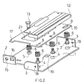
- the invention refers to a support plane 1 with posterior fins 2 folded at right angles to the support plane 1. In front position are then provided fins 3 of the same shape of the posterior fins. The support plane 1 then consists in front of three cylindrical ledges 4 while an,other cylindrical ledge 5 is placed in back position.
- Said anterior and posterior ledges 4 and 5 have the function to keep in position four springs 6 inserted onto the proper ledges.
- the anterior springs 6 are placed over the same three screws 7, passing in holes 8 and into a hole 9 of a second support 10 and screwed in the proper threaded blind holes 11 provide onto the thermal head 12.
- the posterior spirng 6 is instead kept in seat to a screw 13 screwed to the hole of the ledge 5 and passing through the hole 14 provides into the upper support 10.
- the support plane 1 has on the posterior fins 2 circular holes 15 to actuate the assembling of the machine body by means of pins and connection parts and it has rectangular openings 16 to contain in their inside the protrusions 17 of the upper support 10.
- the front fins 3 are equipped with holes 18 for the connection with the machine body.
- the support plane 1 is then centrally provided with a squared hole 19 into which a hook 20 is inserted to be connected with the other its end to the upper support 10.
- Said upper support 10 is then equipped with a big dimension squared hole 21 to permit the wiring assembling.
- the hook 20 puts in compression the spings 6, it limits their trip permitting the relative mobility of the support plane 1 and of the upper support 10 and consequently of the thermal head 12 connected with this last one.
- the elastic connections obtained with the springs 6 permit then a relative rotation of the two support planes 1 and 10 compensing in such a way the wrong dispositions of the paper drive roll in comparison with the thermal head 12.
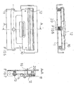
- Figure 4 is lower perspective view.
- sheet 4 figure 5 is upper view.
- Figure 6 is back view.
- Figure 7 is transversal section A-A.
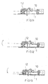
- In sheet 5 are illustrated in frontal views the different dispositions.
- figure 8 is view of the neutral disposition, i.e. without the necessity of compensations for wrong dispositions.
- the figure 9 is view of a longitudinal compensation in one way.
- Figure 10 is view of the longitudinal compensation in the other way.
- In sheet 6 are illustrated in sections the different positions.
- the figure 11 is section view of the neutral position without compensations.
- Figure 12 is view of a transversal compensation in one way.
- Figure 13 is view of a transversal compensation in the other way.
- figura 14 is view of the rotation that comes to compensate the wrong dispositions of the rubbered roll A in comparison with the thermal head 12.
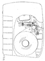
- figure 15 is view of the invention applied inside a thermal printer.
Landscapes
- Electronic Switches (AREA)
- Common Mechanisms (AREA)
Abstract
Description
- It is known that in the thermal printer a big importance has the location of the thermal head on the paper drive roll. Infact, the dispositions not perfectly aligned of the thermal head on the drive roll with the paper that runs, determine a very bad printing quality since the thermal head is not in the optimum position, i.e. tanget to the roll and with the normal passing for the roll rotation pins or at least in a position near the points determined to these ideal lines, but considering that each moving from the optimum disposition is a factor on the printing quality. So to have a ligibility and a good quality printing, it has been necessary to provide mechanics to support the thermal head, to provide support and positioning parts of the drive roll pins extremely precise and with tolerances very restricted, so as to provide a printer body of high definiteness. But it must be considered that the workings, with this requested definiteness, bring a raising of the costs of the end product. Morever, besides the construction inexactnesses in the head disposition and in the printing roll disposition, further inexactnesses in the head and roll dispositions are due to not precise assembling so as due to accidental causes such as knocks or termic expansion. In the prior art are known apparatuses that provide hooking parts of the support roll to the paper but that request to have a machine construction exactness, so as are known apparatuses of compression of the head onto the roll but these do not compensate the constructive plays. The invented apparatus, being a self-aligned support for the head to the position and to the eccentricities of the paper drive roll, permits to have a more easy machine, with less construction problems and so to have a less expensive body machine but always with a good printing quality. The invented apparatus infact is able to compensate the imperfections to the roll or to the roll support carter that are generated during the construction and/or in the printing in these parts or also in case of not precise assembling or for other causes. In this situations, having seats of paper drive roll pins not perfectly disposed, it comes to create positions of the thermal head with the paper drive roll inexact that come to influence the printing quality. Foundamental feature of the invented apparatus is the compensation of the construction and assembling plays which permits the hooking of the roll also not perfect such as, the self-aligned support of the head, comes to salvage said plays thanks to the elasticity of the connections present in its inside. This permits to have a support frame and to have all the connected mechanics less perfect and consequently less expensive. Moreover it is possible to close the printing apparatus with simple hooks without requesting a great precision. The invention refers to a
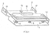
support plane 1 withposterior fins 2 folded at right angles to thesupport plane 1. In front position are then providedfins 3 of the same shape of the posterior fins. Thesupport plane 1 then consists in front of threecylindrical ledges 4 while an,othercylindrical ledge 5 is placed in back position. Said anterior andposterior ledges springs 6 inserted onto the proper ledges. For the vertical arrangement and for keeping in position theanterior springs 6 are placed over the same threescrews 7, passing inholes 8 and into a hole 9 of asecond support 10 and screwed in the proper threadedblind holes 11 provide onto thethermal head 12. Theposterior spirng 6 is instead kept in seat to ascrew 13 screwed to the hole of theledge 5 and passing through thehole 14 provides into theupper support 10. Thesupport plane 1 has on theposterior fins 2circular holes 15 to actuate the assembling of the machine body by means of pins and connection parts and it hasrectangular openings 16 to contain in their inside theprotrusions 17 of theupper support 10. Thefront fins 3 are equipped withholes 18 for the connection with the machine body. Thesupport plane 1 is then centrally provided with asquared hole 19 into which ahook 20 is inserted to be connected with the other its end to theupper support 10. Saidupper support 10 is then equipped with a big dimensionsquared hole 21 to permit the wiring assembling. Thehook 20 puts in compression thespings 6, it limits their trip permitting the relative mobility of thesupport plane 1 and of theupper support 10 and consequently of thethermal head 12 connected with this last one. The elastic connections obtained with thesprings 6 permit then a relative rotation of the twosupport planes thermal head 12. Moreover are compensed wrong dispositions also in transversal way to that determined to the three front springs by means of the posterior spring. So permitting to longitudinally and transversally compensate the disposition mistakes, i.e. compensing by means of the cited elastic connections the wrong longitudinal and transversal positions and all the intermediate positions, the printing head come to be positioned in optimum conditions indipendently to the construction and realization precision of the machine body. The invented head support is illustarated in a merely indicative way in the drawings ofsheets sheet 1 figure 1 is perspective view of the invention with assembled thesupport plane 1, thesprings 6, theupper support 10 and thethermal head 12. Insheet 2 figure 2 is exploded view of the invention. Insheet 3 figure 3 is top perspective view of the invention. Figure 4 is lower perspective view. Insheet 4 figure 5 is upper view. Figure 6 is back view. Figure 7 is transversal section A-A. Insheet 5 are illustrated in frontal views the different dispositions. In detail figure 8 is view of the neutral disposition, i.e. without the necessity of compensations for wrong dispositions. The figure 9 is view of a longitudinal compensation in one way. Figure 10 is view of the longitudinal compensation in the other way. Insheet 6 are illustrated in sections the different positions. In detail the figure 11 is section view of the neutral position without compensations. Figure 12 is view of a transversal compensation in one way. Figure 13 is view of a transversal compensation in the other way. Insheet 7figura 14 is view of the rotation that comes to compensate the wrong dispositions of the rubbered roll A in comparison with thethermal head 12. Insheet 8 figure 15 is view of the invention applied inside a thermal printer.
Claims (7)
- Head support base for thermal printer characterized in thatit provides a support plane (1) with posterior fins (2) folded at right angles to the support plane and equal anterior fins (3) and with three cylindrical anterior ledges (4) and a posterior cylindrical ledge (5) with the function to keep in position four springs (6) inserted onto the proper ledges; and thatthe support plane (1) is centrally provided with a squared hole (19) into which a hook (20) is inserted to be connected with the other its end to the upper support (10); and thatthe hook (20) puts in compression the springs (6) and limits their trip permitting the relative mobility of the support plane (1) and of the upper support (10) and consequently of the thermal head (12) conected with this last one.
- Head support base for thermal printer, as per claim 1, characterized in that for the arrangement and for keeping in position the anterior springs (6) are placed over the same three screws (7), passing in holes (8) and into a hole (9) of a second support (10) and screwed in the proper threaded blind holes (11) provide onto the thermal head (12), whereas the posterior spring (6) is kept in seat to a screw (13) screwed to the hole of the ledge (5) and passing through the hole (14) provides into the supper support (10).
- Head support base for thermal printer, as per claim 1, characterized in that the support plane (1) has on the posterior fins (2) circular holes (15) to actuate the assembling of the machine body by means of pins and connection parts and it has rectangular openings (16) to contain in their inside the protrusions (17) of the upper support (10).
- Head support base for thermal printer, as per claim 1, characterized in that the front fins (3) are equipped with holes (18) for the connection with the machine body.
- Head support base for thermal printer, as per claim 1, characterized in that the elastic connections obtained with the springs (6) permit a relative rotation of the two support planes (1, 10) compensing in such a way the wrong dispositions of the paper drive roll in comparison with the thermal head (12).
- Head support base for thermal printer, as per claim 1, characterized in that are compensed wrong dispositions' also in transversal way to that determined to the three front springs by means of the posterior spring.
- Head support base for thermal printer, as per claim 1, characterized in that permitting to longitudinally and transversally compensate the disposition mistakes, the printing head comes to be positioned in optimum conditions indipendently to the construction and realization precision of the machine body.
Priority Applications (4)
| Application Number | Priority Date | Filing Date | Title |
|---|---|---|---|
| DE60313774T DE60313774D1 (en) | 2003-09-16 | 2003-09-16 | Print head carrier for thermal printer |
| AT03425599T ATE361841T1 (en) | 2003-09-16 | 2003-09-16 | PRINT HEAD CARRIER FOR THERMAL PRINTER |
| EP03425599A EP1516741B1 (en) | 2003-09-16 | 2003-09-16 | Head support base for thermal printer |
| US10/939,043 US7175356B2 (en) | 2003-09-16 | 2004-09-10 | Head support base for thermal printer |
Applications Claiming Priority (1)
| Application Number | Priority Date | Filing Date | Title |
|---|---|---|---|
| EP03425599A EP1516741B1 (en) | 2003-09-16 | 2003-09-16 | Head support base for thermal printer |
Publications (2)
| Publication Number | Publication Date |
|---|---|
| EP1516741A1 true EP1516741A1 (en) | 2005-03-23 |
| EP1516741B1 EP1516741B1 (en) | 2007-05-09 |
Family
ID=34178693
Family Applications (1)
| Application Number | Title | Priority Date | Filing Date |
|---|---|---|---|
| EP03425599A Expired - Lifetime EP1516741B1 (en) | 2003-09-16 | 2003-09-16 | Head support base for thermal printer |
Country Status (4)
| Country | Link |
|---|---|
| US (1) | US7175356B2 (en) |
| EP (1) | EP1516741B1 (en) |
| AT (1) | ATE361841T1 (en) |
| DE (1) | DE60313774D1 (en) |
Families Citing this family (7)
| Publication number | Priority date | Publication date | Assignee | Title |
|---|---|---|---|---|
| TWI291417B (en) * | 2006-08-10 | 2007-12-21 | Hi Touch Imaging Tech Co Ltd | Printer having a printhead with fixed angle |
| TWM331707U (en) * | 2007-11-28 | 2008-05-01 | Icp Electronics Inc | Lottery ticket printer |
| CN105500699A (en) * | 2014-09-22 | 2016-04-20 | 三纬国际立体列印科技股份有限公司 | The horizontal correction mechanism of three-dimensional list machine |
| JP6932203B2 (en) * | 2017-11-15 | 2021-09-08 | アルプスアルパイン株式会社 | Image forming device |
| JP7287818B2 (en) * | 2019-03-29 | 2023-06-06 | 富士通コンポーネント株式会社 | printer device |
| CN116221548B (en) * | 2022-06-30 | 2024-04-19 | 珠海恒盛条码设备有限公司 | Bottom bracing mechanism and printing device |
| CN117841535B (en) * | 2024-01-12 | 2025-09-19 | 厦门汉印股份有限公司 | Printhead assembly and thermal printer |
Citations (4)
| Publication number | Priority date | Publication date | Assignee | Title |
|---|---|---|---|---|
| EP0700789A1 (en) * | 1994-09-09 | 1996-03-13 | Tohoku Ricoh Co., Ltd. | Thermal printer |
| US5594487A (en) * | 1993-10-13 | 1997-01-14 | Kabushiki Kaisha Tec | Thermal head supporting device |
| EP0765761A1 (en) * | 1995-09-29 | 1997-04-02 | Anritsu Corporation | Thermal printing apparatus |
| JPH10119327A (en) * | 1996-10-24 | 1998-05-12 | Tec Corp | Thermal printer head structure |
Family Cites Families (1)
| Publication number | Priority date | Publication date | Assignee | Title |
|---|---|---|---|---|
| US5570121A (en) * | 1993-12-20 | 1996-10-29 | Monarch Marking Systems, Inc. | Printer |
-
2003
- 2003-09-16 DE DE60313774T patent/DE60313774D1/en not_active Expired - Lifetime
- 2003-09-16 EP EP03425599A patent/EP1516741B1/en not_active Expired - Lifetime
- 2003-09-16 AT AT03425599T patent/ATE361841T1/en not_active IP Right Cessation
-
2004
- 2004-09-10 US US10/939,043 patent/US7175356B2/en not_active Expired - Lifetime
Patent Citations (4)
| Publication number | Priority date | Publication date | Assignee | Title |
|---|---|---|---|---|
| US5594487A (en) * | 1993-10-13 | 1997-01-14 | Kabushiki Kaisha Tec | Thermal head supporting device |
| EP0700789A1 (en) * | 1994-09-09 | 1996-03-13 | Tohoku Ricoh Co., Ltd. | Thermal printer |
| EP0765761A1 (en) * | 1995-09-29 | 1997-04-02 | Anritsu Corporation | Thermal printing apparatus |
| JPH10119327A (en) * | 1996-10-24 | 1998-05-12 | Tec Corp | Thermal printer head structure |
Non-Patent Citations (1)
| Title |
|---|
| PATENT ABSTRACTS OF JAPAN vol. 1998, no. 10 31 August 1998 (1998-08-31) * |
Also Published As
| Publication number | Publication date |
|---|---|
| EP1516741B1 (en) | 2007-05-09 |
| US7175356B2 (en) | 2007-02-13 |
| US20050117953A1 (en) | 2005-06-02 |
| DE60313774D1 (en) | 2007-06-21 |
| ATE361841T1 (en) | 2007-06-15 |
Similar Documents
| Publication | Publication Date | Title |
|---|---|---|
| CN100537255C (en) | Positioning mechanism for direct marking printhead and method of positioning printhead in printer | |
| US10046580B2 (en) | Mounting structure for a plurality of print head units | |
| CN204725855U (en) | 3D model printer print tray plate rail height level's adjusting device and 3D printer | |
| EP1516741B1 (en) | Head support base for thermal printer | |
| US9119473B2 (en) | Seat with adjustable back profile | |
| BR112019013110A2 (en) | printhead tangential adjustment mechanism | |
| JPH05155100A (en) | Thermal head holding mechanism | |
| US20030081972A1 (en) | Method and apparatus for clamping and adjusting an anti-rotation rail to adjust printhead to platen/media spacing in a printer | |
| US2234170A (en) | Means for preparing printing plates for application to printing cylinders | |
| JP4845764B2 (en) | Printer | |
| US7303165B2 (en) | Roll positioning mechanism | |
| CN110207962B (en) | Service life evaluation tester for paper feeding rubber roller of printer or copying machine | |
| GB2051567A (en) | Aircraft seat | |
| JP2567269B2 (en) | Ink rail for printing machine | |
| JP2761443B2 (en) | Printing device | |
| JPS6347483Y2 (en) | ||
| CN211140099U (en) | Printing rubber roll rack | |
| JP2000318888A5 (en) | ||
| US1097494A (en) | Copy-holder. | |
| US2355396A (en) | Float | |
| US985376A (en) | Paper-machine. | |
| US1080347A (en) | Multiple-writing machine. | |
| JP3718163B2 (en) | Paper feeder | |
| US899363A (en) | Printing-frame. | |
| US1458269A (en) | Typewriting machine |
Legal Events
| Date | Code | Title | Description |
|---|---|---|---|
| PUAI | Public reference made under article 153(3) epc to a published international application that has entered the european phase |
Free format text: ORIGINAL CODE: 0009012 |
|
| AK | Designated contracting states |
Kind code of ref document: A1 Designated state(s): AT BE BG CH CY CZ DE DK EE ES FI FR GB GR HU IE IT LI LU MC NL PT RO SE SI SK TR |
|
| AX | Request for extension of the european patent |
Extension state: AL LT LV MK |
|
| AKX | Designation fees paid | ||
| REG | Reference to a national code |
Ref country code: DE Ref legal event code: 8566 |
|
| RBV | Designated contracting states (corrected) |
Designated state(s): AT BE BG CH CY CZ DE DK EE ES FI FR GB GR HU IE IT LI LU MC NL PT RO SE SI SK TR |
|
| 17P | Request for examination filed |
Effective date: 20051212 |
|
| GRAP | Despatch of communication of intention to grant a patent |
Free format text: ORIGINAL CODE: EPIDOSNIGR1 |
|
| GRAS | Grant fee paid |
Free format text: ORIGINAL CODE: EPIDOSNIGR3 |
|
| GRAA | (expected) grant |
Free format text: ORIGINAL CODE: 0009210 |
|
| AK | Designated contracting states |
Kind code of ref document: B1 Designated state(s): AT BE BG CH CY CZ DE DK EE ES FI FR GB GR HU IE IT LI LU MC NL PT RO SE SI SK TR |
|
| PG25 | Lapsed in a contracting state [announced via postgrant information from national office to epo] |
Ref country code: FI Free format text: LAPSE BECAUSE OF FAILURE TO SUBMIT A TRANSLATION OF THE DESCRIPTION OR TO PAY THE FEE WITHIN THE PRESCRIBED TIME-LIMIT Effective date: 20070509 Ref country code: CH Free format text: LAPSE BECAUSE OF FAILURE TO SUBMIT A TRANSLATION OF THE DESCRIPTION OR TO PAY THE FEE WITHIN THE PRESCRIBED TIME-LIMIT Effective date: 20070509 Ref country code: LI Free format text: LAPSE BECAUSE OF FAILURE TO SUBMIT A TRANSLATION OF THE DESCRIPTION OR TO PAY THE FEE WITHIN THE PRESCRIBED TIME-LIMIT Effective date: 20070509 |
|
| REG | Reference to a national code |
Ref country code: GB Ref legal event code: FG4D |
|
| REG | Reference to a national code |
Ref country code: CH Ref legal event code: EP |
|
| REG | Reference to a national code |
Ref country code: IE Ref legal event code: FG4D |
|
| REF | Corresponds to: |
Ref document number: 60313774 Country of ref document: DE Date of ref document: 20070621 Kind code of ref document: P |
|
| PG25 | Lapsed in a contracting state [announced via postgrant information from national office to epo] |
Ref country code: SE Free format text: LAPSE BECAUSE OF FAILURE TO SUBMIT A TRANSLATION OF THE DESCRIPTION OR TO PAY THE FEE WITHIN THE PRESCRIBED TIME-LIMIT Effective date: 20070809 |
|
| PG25 | Lapsed in a contracting state [announced via postgrant information from national office to epo] |
Ref country code: ES Free format text: LAPSE BECAUSE OF FAILURE TO SUBMIT A TRANSLATION OF THE DESCRIPTION OR TO PAY THE FEE WITHIN THE PRESCRIBED TIME-LIMIT Effective date: 20070820 |
|
| NLV1 | Nl: lapsed or annulled due to failure to fulfill the requirements of art. 29p and 29m of the patents act | ||
| REG | Reference to a national code |
Ref country code: CH Ref legal event code: PL |
|
| PG25 | Lapsed in a contracting state [announced via postgrant information from national office to epo] |
Ref country code: AT Free format text: LAPSE BECAUSE OF FAILURE TO SUBMIT A TRANSLATION OF THE DESCRIPTION OR TO PAY THE FEE WITHIN THE PRESCRIBED TIME-LIMIT Effective date: 20070509 |
|
| PG25 | Lapsed in a contracting state [announced via postgrant information from national office to epo] |
Ref country code: BE Free format text: LAPSE BECAUSE OF FAILURE TO SUBMIT A TRANSLATION OF THE DESCRIPTION OR TO PAY THE FEE WITHIN THE PRESCRIBED TIME-LIMIT Effective date: 20070509 |
|
| EN | Fr: translation not filed | ||
| PG25 | Lapsed in a contracting state [announced via postgrant information from national office to epo] |
Ref country code: NL Free format text: LAPSE BECAUSE OF FAILURE TO SUBMIT A TRANSLATION OF THE DESCRIPTION OR TO PAY THE FEE WITHIN THE PRESCRIBED TIME-LIMIT Effective date: 20070509 Ref country code: BG Free format text: LAPSE BECAUSE OF FAILURE TO SUBMIT A TRANSLATION OF THE DESCRIPTION OR TO PAY THE FEE WITHIN THE PRESCRIBED TIME-LIMIT Effective date: 20070809 Ref country code: CZ Free format text: LAPSE BECAUSE OF FAILURE TO SUBMIT A TRANSLATION OF THE DESCRIPTION OR TO PAY THE FEE WITHIN THE PRESCRIBED TIME-LIMIT Effective date: 20070509 Ref country code: SI Free format text: LAPSE BECAUSE OF FAILURE TO SUBMIT A TRANSLATION OF THE DESCRIPTION OR TO PAY THE FEE WITHIN THE PRESCRIBED TIME-LIMIT Effective date: 20070509 Ref country code: PT Free format text: LAPSE BECAUSE OF FAILURE TO SUBMIT A TRANSLATION OF THE DESCRIPTION OR TO PAY THE FEE WITHIN THE PRESCRIBED TIME-LIMIT Effective date: 20071009 Ref country code: DK Free format text: LAPSE BECAUSE OF FAILURE TO SUBMIT A TRANSLATION OF THE DESCRIPTION OR TO PAY THE FEE WITHIN THE PRESCRIBED TIME-LIMIT Effective date: 20070509 |
|
| PG25 | Lapsed in a contracting state [announced via postgrant information from national office to epo] |
Ref country code: SK Free format text: LAPSE BECAUSE OF FAILURE TO SUBMIT A TRANSLATION OF THE DESCRIPTION OR TO PAY THE FEE WITHIN THE PRESCRIBED TIME-LIMIT Effective date: 20070509 |
|
| PLBE | No opposition filed within time limit |
Free format text: ORIGINAL CODE: 0009261 |
|
| STAA | Information on the status of an ep patent application or granted ep patent |
Free format text: STATUS: NO OPPOSITION FILED WITHIN TIME LIMIT |
|
| 26N | No opposition filed |
Effective date: 20080212 |
|
| PG25 | Lapsed in a contracting state [announced via postgrant information from national office to epo] |
Ref country code: MC Free format text: LAPSE BECAUSE OF NON-PAYMENT OF DUE FEES Effective date: 20070930 Ref country code: DE Free format text: LAPSE BECAUSE OF FAILURE TO SUBMIT A TRANSLATION OF THE DESCRIPTION OR TO PAY THE FEE WITHIN THE PRESCRIBED TIME-LIMIT Effective date: 20070810 Ref country code: GR Free format text: LAPSE BECAUSE OF FAILURE TO SUBMIT A TRANSLATION OF THE DESCRIPTION OR TO PAY THE FEE WITHIN THE PRESCRIBED TIME-LIMIT Effective date: 20070810 Ref country code: IT Free format text: LAPSE BECAUSE OF FAILURE TO SUBMIT A TRANSLATION OF THE DESCRIPTION OR TO PAY THE FEE WITHIN THE PRESCRIBED TIME-LIMIT Effective date: 20070509 |
|
| GBPC | Gb: european patent ceased through non-payment of renewal fee |
Effective date: 20070916 |
|
| PG25 | Lapsed in a contracting state [announced via postgrant information from national office to epo] |
Ref country code: RO Free format text: LAPSE BECAUSE OF FAILURE TO SUBMIT A TRANSLATION OF THE DESCRIPTION OR TO PAY THE FEE WITHIN THE PRESCRIBED TIME-LIMIT Effective date: 20070509 |
|
| PG25 | Lapsed in a contracting state [announced via postgrant information from national office to epo] |
Ref country code: FR Free format text: LAPSE BECAUSE OF FAILURE TO SUBMIT A TRANSLATION OF THE DESCRIPTION OR TO PAY THE FEE WITHIN THE PRESCRIBED TIME-LIMIT Effective date: 20080104 |
|
| PG25 | Lapsed in a contracting state [announced via postgrant information from national office to epo] |
Ref country code: IE Free format text: LAPSE BECAUSE OF NON-PAYMENT OF DUE FEES Effective date: 20070917 |
|
| PG25 | Lapsed in a contracting state [announced via postgrant information from national office to epo] |
Ref country code: GB Free format text: LAPSE BECAUSE OF NON-PAYMENT OF DUE FEES Effective date: 20070916 |
|
| PG25 | Lapsed in a contracting state [announced via postgrant information from national office to epo] |
Ref country code: EE Free format text: LAPSE BECAUSE OF FAILURE TO SUBMIT A TRANSLATION OF THE DESCRIPTION OR TO PAY THE FEE WITHIN THE PRESCRIBED TIME-LIMIT Effective date: 20070509 |
|
| PG25 | Lapsed in a contracting state [announced via postgrant information from national office to epo] |
Ref country code: CY Free format text: LAPSE BECAUSE OF FAILURE TO SUBMIT A TRANSLATION OF THE DESCRIPTION OR TO PAY THE FEE WITHIN THE PRESCRIBED TIME-LIMIT Effective date: 20070509 |
|
| PG25 | Lapsed in a contracting state [announced via postgrant information from national office to epo] |
Ref country code: LU Free format text: LAPSE BECAUSE OF NON-PAYMENT OF DUE FEES Effective date: 20070916 |
|
| PG25 | Lapsed in a contracting state [announced via postgrant information from national office to epo] |
Ref country code: TR Free format text: LAPSE BECAUSE OF FAILURE TO SUBMIT A TRANSLATION OF THE DESCRIPTION OR TO PAY THE FEE WITHIN THE PRESCRIBED TIME-LIMIT Effective date: 20070509 Ref country code: HU Free format text: LAPSE BECAUSE OF FAILURE TO SUBMIT A TRANSLATION OF THE DESCRIPTION OR TO PAY THE FEE WITHIN THE PRESCRIBED TIME-LIMIT Effective date: 20071110 |