EP1516641B1 - Verfahren und System zur Integration von Aktivitäten eines Beatmungsgerätes und einer medizinische Vorrichtung - Google Patents
Verfahren und System zur Integration von Aktivitäten eines Beatmungsgerätes und einer medizinische Vorrichtung Download PDFInfo
- Publication number
- EP1516641B1 EP1516641B1 EP04255669A EP04255669A EP1516641B1 EP 1516641 B1 EP1516641 B1 EP 1516641B1 EP 04255669 A EP04255669 A EP 04255669A EP 04255669 A EP04255669 A EP 04255669A EP 1516641 B1 EP1516641 B1 EP 1516641B1
- Authority
- EP
- European Patent Office
- Prior art keywords
- ventilator
- control unit
- drug delivery
- monitoring device
- delivery device
- Prior art date
- Legal status (The legal status is an assumption and is not a legal conclusion. Google has not performed a legal analysis and makes no representation as to the accuracy of the status listed.)
- Expired - Lifetime
Links
- 238000000034 method Methods 0.000 title claims description 98
- 230000000694 effects Effects 0.000 title description 3
- 238000012806 monitoring device Methods 0.000 claims description 94
- 238000012377 drug delivery Methods 0.000 claims description 60
- 238000004891 communication Methods 0.000 claims description 35
- 238000009423 ventilation Methods 0.000 claims description 35
- 239000006199 nebulizer Substances 0.000 claims description 31
- 239000003814 drug Substances 0.000 claims description 21
- 230000004913 activation Effects 0.000 claims description 18
- 229940079593 drug Drugs 0.000 claims description 18
- 230000004048 modification Effects 0.000 claims description 11
- 238000012986 modification Methods 0.000 claims description 11
- 238000002663 nebulization Methods 0.000 claims description 8
- 230000004044 response Effects 0.000 claims description 5
- 230000001360 synchronised effect Effects 0.000 claims description 3
- 239000007789 gas Substances 0.000 description 47
- 238000002644 respiratory therapy Methods 0.000 description 23
- 230000000241 respiratory effect Effects 0.000 description 16
- 230000006399 behavior Effects 0.000 description 15
- 238000012544 monitoring process Methods 0.000 description 15
- 238000003384 imaging method Methods 0.000 description 14
- 238000005259 measurement Methods 0.000 description 12
- 210000004072 lung Anatomy 0.000 description 10
- 230000000977 initiatory effect Effects 0.000 description 9
- 238000002560 therapeutic procedure Methods 0.000 description 8
- 230000029058 respiratory gaseous exchange Effects 0.000 description 5
- 230000000737 periodic effect Effects 0.000 description 4
- 230000001052 transient effect Effects 0.000 description 4
- 230000009471 action Effects 0.000 description 3
- 230000003115 biocidal effect Effects 0.000 description 2
- 230000008859 change Effects 0.000 description 2
- 230000003434 inspiratory effect Effects 0.000 description 2
- 208000032376 Lung infection Diseases 0.000 description 1
- 239000003242 anti bacterial agent Substances 0.000 description 1
- 238000013459 approach Methods 0.000 description 1
- QVGXLLKOCUKJST-UHFFFAOYSA-N atomic oxygen Chemical compound [O] QVGXLLKOCUKJST-UHFFFAOYSA-N 0.000 description 1
- 238000009530 blood pressure measurement Methods 0.000 description 1
- 230000000747 cardiac effect Effects 0.000 description 1
- 238000002591 computed tomography Methods 0.000 description 1
- 230000008021 deposition Effects 0.000 description 1
- 230000000881 depressing effect Effects 0.000 description 1
- 230000000994 depressogenic effect Effects 0.000 description 1
- 238000002059 diagnostic imaging Methods 0.000 description 1
- 230000006872 improvement Effects 0.000 description 1
- 230000002779 inactivation Effects 0.000 description 1
- 230000010354 integration Effects 0.000 description 1
- 239000000463 material Substances 0.000 description 1
- 239000001301 oxygen Substances 0.000 description 1
- 229910052760 oxygen Inorganic materials 0.000 description 1
- 230000001706 oxygenating effect Effects 0.000 description 1
- 238000006213 oxygenation reaction Methods 0.000 description 1
- 238000005070 sampling Methods 0.000 description 1
- 229940126585 therapeutic drug Drugs 0.000 description 1
Images

Classifications
-
- A—HUMAN NECESSITIES
- A61—MEDICAL OR VETERINARY SCIENCE; HYGIENE
- A61M—DEVICES FOR INTRODUCING MEDIA INTO, OR ONTO, THE BODY; DEVICES FOR TRANSDUCING BODY MEDIA OR FOR TAKING MEDIA FROM THE BODY; DEVICES FOR PRODUCING OR ENDING SLEEP OR STUPOR
- A61M16/00—Devices for influencing the respiratory system of patients by gas treatment, e.g. ventilators; Tracheal tubes
- A61M16/021—Devices for influencing the respiratory system of patients by gas treatment, e.g. ventilators; Tracheal tubes operated by electrical means
-
- A—HUMAN NECESSITIES
- A61—MEDICAL OR VETERINARY SCIENCE; HYGIENE
- A61M—DEVICES FOR INTRODUCING MEDIA INTO, OR ONTO, THE BODY; DEVICES FOR TRANSDUCING BODY MEDIA OR FOR TAKING MEDIA FROM THE BODY; DEVICES FOR PRODUCING OR ENDING SLEEP OR STUPOR
- A61M11/00—Sprayers or atomisers specially adapted for therapeutic purposes
-
- A—HUMAN NECESSITIES
- A61—MEDICAL OR VETERINARY SCIENCE; HYGIENE
- A61M—DEVICES FOR INTRODUCING MEDIA INTO, OR ONTO, THE BODY; DEVICES FOR TRANSDUCING BODY MEDIA OR FOR TAKING MEDIA FROM THE BODY; DEVICES FOR PRODUCING OR ENDING SLEEP OR STUPOR
- A61M2205/00—General characteristics of the apparatus
- A61M2205/35—Communication
- A61M2205/3546—Range
- A61M2205/3569—Range sublocal, e.g. between console and disposable
-
- A—HUMAN NECESSITIES
- A61—MEDICAL OR VETERINARY SCIENCE; HYGIENE
- A61M—DEVICES FOR INTRODUCING MEDIA INTO, OR ONTO, THE BODY; DEVICES FOR TRANSDUCING BODY MEDIA OR FOR TAKING MEDIA FROM THE BODY; DEVICES FOR PRODUCING OR ENDING SLEEP OR STUPOR
- A61M2230/00—Measuring parameters of the user
- A61M2230/40—Respiratory characteristics
- A61M2230/43—Composition of exhalation
Definitions
- the present invention relates to the field of providing respiratory therapy to a patient. More particularly, the invention relates to a method of integrating the active behaviors of a ventilator and a medical device or a monitoring device to provide improved respiratory therapy or monitoring behaviors.
- Contemporary ventilators often provide for the use of ventilation "procedures", which may require a transient change in ventilator operation.
- ventilation procedures include pre-oxygenating a patient for several minutes prior to suctioning the airway, transiently occluding the patient circuit at the end of an exhalation, changing the O 2 delivery percentage for the purpose of Functional Residual Capacity measurement, etc.
- ventilators and monitoring devices have typically been separate units having their own displays and user interfaces.
- the present invention it is recognized as desirable to integrate the ventilator and monitoring device functions to operate as a single respiratory care system.
- monitoring data from the monitoring device is displayed together with ventilation therapy information on a single configurable display.
- the prior art devices do not fully integrate the active behaviors of the ventilator and the monitoring device.
- prior art monitoring and ventilation devices have been integrated in terms of the data that is moved between them, they are not integrated as to their active behaviors so as to achieve desired clinical performance.
- the prior art ventilation and monitoring devices thus require individual adjustments by the user to effect a desired therapy or simple physiologic measurement behavior. This can require time consuming and tedious manual operations and therefore undesirably reduces system efficiency.
- ventilators Like the relationship that exists between ventilation and monitoring devices, a similar inter-relationship exists between currently available ventilators and various other medical devices. For example, imaging devices such as MRI, CAT scans and radiograms, as well as drug delivery devices such as nebulizers and syringe pumps, are utilized in the same operating environment as the prior art ventilation devices.
- imaging devices such as MRI, CAT scans and radiograms
- drug delivery devices such as nebulizers and syringe pumps
- the ventilator must be modified in order to provide the optimal conditions for the performance of the medical procedure. For example, at the start of a lung radiogram, it is desirable for the ventilator to inflate the lungs to a specific pressure level. In currently available systems, the ventilator must be manually operated independently from the operation of the radiogram to obtain the desired lung pressure.
- US 4,387,722 discloses an apparatus for triggering an X-ray machine in accordance with the monitored respiration of a subject. In a separate operation, the monitoring of respiration may be used to adjust a ventilator.
- the invention provides a method of integrating the active behaviors of a ventilator and either a monitoring device or other medical device, the method comprising the steps of: providing a control unit in communication with the ventilator, the monitoring device and the drug delivery device; detecting the activation of one of the ventilator, monitoring device and drug delivery device at the control unit ; and generating a modification signal from the control unit to automatically modify an operating condition of at least two of the drug delivery device, the monitoring device and the ventilator in response to the activation of one of the ventilator, monitoring device and drug delivery device, wherein the drug delivery device is a nebulizer, activation of the nebulizer delivers an aerosolized drug into a flow of ventilation gas from the ventilator, and the operating condition of the monitoring device is modified to prevent the intake of the ventilation gas.
- the control unit may generate a second modification signal upon detecting termination of said activation of one of the ventilator, monitoring device and drug delivery device, and the monitoring device and drug delivery device may return to their initial operating conditions upon receipt of the second modification signal.
- the operating condition of the drug delivery device can be modified such that the drug delivery device operation is synchronized with the operation of the ventilator to more effectively deliver the drug.
- the invention also provides a control system for automatically integrating the operation of a ventilator, a drug delivery device and a gas monitoring device, the system comprising: a control unit in communication with the ventilator and operable to modify the operation of the ventilator, the drug delivery device and the monitoring device; a communication link between the control unit and the monitoring device such that the control unit can communicate with the monitoring device through the communication link; and a communication link between the control unit and the drug delivery device such that the control unit can communicate with the drug delivery device through the communication link, wherein the control unit is operable to detect the activation of one of the ventilator, monitoring device and drug delivery device and to automatically modify the operation of at least two of the monitoring device, the drug delivery device and the ventilator in response to said activation of one of the ventilator, monitoring device and drug delivery device, and wherein the drug delivery device is a nebulizer, the control unit operates to coordinate the activation of the nebulizer to entrain an aerosolized drug into the flow of ventilation gas in the ventilator, and the operating condition of the
- the control unit can be is integrated into the ventilator.
- the drug delivery device can includes the control unit and the drug delivery device control unit be integrated into the ventilator.
- the drug delivery device can include a control unit remotely located from the ventilator, and the ventilator control unit communicate to the drug delivery device control unit over a communication link.
- the communication link may be a RS-422 connection.
- a respiratory therapy procedure is a combined procedure carried out by the ventilator control unit and two or more of a ventilator, a monitoring device, drug delivery device, imaging device or other medical device.
- the ventilator is capable of performing ventilation procedures, while the medical device can perform multiple medical procedures and the monitoring device can perform multiple monitoring procedures.
- the present invention integrates the transient changes in the procedures of these devices during a respiratory therapy procedure to optimize the performance of the respiratory therapy procedure through the use of a control unit preferably contained in the ventilator.
- An exemplary embodiment of the present invention relates to a method wherein a ventilator is integrated with a respiratory gas monitoring device and the function of the respiratory gas monitoring device is changed based on initiation of a respiratory therapy procedure.
- a ventilator is integrated with a respiratory gas monitoring device and the function of the respiratory gas monitoring device is changed based on initiation of a respiratory therapy procedure.
- various other types of monitoring devices can be utilized with the present invention.
- monitoring device will describe a broad class of devices, while the term respiratory gas monitoring device will describe a specific type of monitoring device.
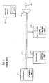
- a ventilator 10 provides a flow of ventilation gas through a patient conduit 12 to the patient 14.
- the patient receives the flow of ventilation gas through a gas mask 16, although various other types of delivery connections are contemplated as being within the scope of the present invention.
- the patient conduit 12 can receive a dose of medication from a nebulizer 18. Additionally, the patient conduit 12 can be coupled to a respiratory gas monitoring device 20 that operates to monitor the contents and quality of the ventilator flow to the patient 14.
- the system shown in Fig. 1 may also include an imaging device 22 that can be separately operated to take desired images of the patient during the use of the ventilator 10.
- a respiratory therapy procedure is the application of nebulized medicine to a breathing circuit during ventilation therapy.
- a drug delivery device such as the nebulizer 18 introduces aerosolized medication periodically as prescribed into the breathable gas flowing through the inspiratory patient conduit 12 of the patient circuit and ultimately to the patient's airway and lungs.
- the medicine typically used in respiratory care such as Albutoral
- the materials can cause damage to components such as pumps and infrared benches found in respiratory gas monitoring devices 20.
- nebulizer 18 and respiratory gas monitoring device 20 do not communicate with each other, during the operation of the nebulizer 18 the operation of the gas monitoring device 20 must be manually suspended while the nebulizer 18 introduces the aerosolized medication into the patient conduit 12. Once the desired amount of nebulized drug has been delivered, (sometimes 10-30 minutes later), the user needs to remember to return into the patient's room to reinitiate the gas monitoring device 20. In many cases, the nebulizer delivers drugs several times a day, which can become a tiresome and time-consuming proposition for the user.
- the ventilator and integrated display 24 provide a ventilation gas flow through the patient conduit 12 to the patient. 14.
- the nebulizer 18 and a monitoring device, such as a respiratory gas monitoring device 20 are each in communication with the patient conduit 12.
- the nebulizer 18 is able to introduce an aerosolized medication into the flow of gas within the patient conduit 12, while the gas monitoring device 20 is able to make the desired measurements of the ventilator gas flow as desired.
- the system includes an imaging device 22, in addition to various other medical devices 26.
- the control unit 27 of ventilator and display 24 is in communication with a control unit 29 of the nebulizer 18 over a communication link 28.
- the control unit of the ventilator and display 24 is in communication with the respiratory gas monitoring device 20 over a second communication link 30. In this manner, the control unit 27 of the ventilator and display 24 can communicate in a bi-directional manner with both the nebulizer 18 and the respiratory gas monitoring device 20.
- control unit 27 of the ventilator and display 24 is also in 2-way communication with the imaging device 22 over a third communication link 32 and with the other medical devices 26 over additional communication links 34.
- the communication link 28 between the ventilator 24 and the nebulizer 18 is an RS-422 connection.
- all of the communication links 28, 30, 32 and 34 could be replaced by any method of communicating over a point to point network.
- electrical and RF communication methodologies are contemplated as being within the scope of the present invention.
- the nebulizer 18, monitoring device 20, and imaging device 22 are separate components from the ventilator 24 such that each of the devices includes it own control unit.
- the control unit 27 from the ventilator 24 communicates in a bi-directional manner with the control unit 27 for the nebulizer 18.
- the nebulizer 18, gas monitoring device 20 and imaging device 22 are located remotely from the ventilator 24 such that the communication link between the various devices is typically carried out by a RS-422 cable.
- the control units for any or all of the nebulizer 18, gas monitoring device 20 and imaging device 22 could be integrated into a single cabinet or structure with the ventilator and display 24.
- the RS-422 communication links could be replaced by conventional wiring. It is also contemplated that some of the communication links between the control unit and the remote devices may be uni-directional.
- the control unit of the device may consist only of analog circuits necessary to activate the monitor or medical device.
- the nebulizer 18 may include a control unit consisting of only analog electronic circuits necessary to power the nebulizer. The control signal to such a nebulizer would be the power control input for the analog circuits.
- the control unit 27 contained within the ventilator 24 is able to communicate with multiple different devices each used during the ventilation and monitoring of a patient 14.
- the ventilator 24 is able to communicate with and provide control signals to the nebulizer 18, gas monitoring device 20, imaging device 22, and various other medical devices 26.
- the single control unit 27 of the ventilator 24 is able to trigger and provide control signals to the various components based upon the ventilation therapy procedures being carried out by the ventilator 24.
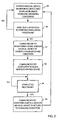
- the medical device, monitoring device and ventilator are all initially operated under standard operating conditions, as shown in step 36.
- the control unit contained within the ventilator monitors the operation of the medical device, the monitoring device and the ventilator to determine whether any procedures are to be performed by any of these components.
- the control unit of the ventilator determines whether the ventilator has initiated a respiratory therapy procedure, either automatically or by a manual user input. If the ventilator has not initiated such a procedure, the control unit returns to the initial step 36 and continues to monitor for the initiation of a respiratory therapy procedure.
- control unit of the ventilator detects the initiation of a respiratory therapy procedure, the control unit sends a signal to the ventilator, monitoring device and the medical device to operate under modified operating conditions, if modified conditions are required to optimize the respiratory therapy procedure.
- the ventilator can be configured to perform a periodic sigh (greater than normal inspiration) and such procedure should not interfere with the gas monitoring trend sample function.
- the control unit of the ventilator sends a modification signal to the control unit of the monitoring device, causing the monitoring device to suspend trend operation during the periodic sigh.
- the ventilator control unit provides the required signal to the medical device, causing the medical device to operate under modified conditions.
- control unit signals to the ventilator to begin its ventilation procedure in step 42.
- the combination of these events comprises the respiratory . therapy procedure being coordinated by the control unit.
- control unit communicates to the monitoring device and medical device to return to the standard operating conditions, as indicated in step 46.
- control unit coordinates the operation of not only the ventilator operating parameters, but also the operation of related medical devices and monitoring devices utilized throughout the system.
- the invention thus solves the drawbacks of the prior art by automatically modifying the behavior of the monitoring device in response to the activation (or inactivation) of the respiratory therapy procedure, increasing efficiency and accuracy of the respiratory therapy procedure.
- the above-described method is useful for a wide variety of respiratory therapy applications, including the performance of certain monitoring calibrations (e.g. a 100% oxygen span calibration on the monitoring device in association with a pre-oxygenation maneuver) and the initiation of monitoring data samples at appropriate times in a procedure cycle (e.g. sampling respiratory gases at specific points in a procedure).
- certain monitoring calibrations e.g. a 100% oxygen span calibration on the monitoring device in association with a pre-oxygenation maneuver
- the initiation of monitoring data samples at appropriate times in a procedure cycle e.g. sampling respiratory gases at specific points in a procedure.
- the control unit integrates the transient changes in operation of the ventilator, monitoring device or other medical device to optimize the procedure.
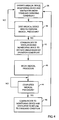
- Fig. 4 in an alternate method of the present invention, the ventilator, monitoring device and medical device are operated under normal operating conditions, as shown in step 48.
- the control unit of the ventilator is notified whether the medical device needs to carry out a medical procedure or whether the monitoring device needs to carry out a monitoring procedure. If the medical/monitoring device is not issuing a signal indicating the beginning of a medical/monitoring procedure, the system continues to operate under normal conditions.
- Fig. 4 illustrates the initiation of a medical procedure with the understanding that the initiation of a monitoring procedure would be similar to the illustration of Fig. 4
- the medical procedure is initiated by a user by depressing a button or display panel on the medical device. Once a user has depressed the required activation member, the medical device generates a signal to the ventilator control unit indicating that the medical device is about to begin a medical procedure. In this manner, the activation of a medical procedure at a remote medical device is communicated to the remote control unit of the ventilator.
- the control unit determines in step 50 that medical device needs to begin a medical procedure, the control unit generates a modification signal to the monitoring device to modify the normal operating condition of the monitoring device. Additionally, the control unit modifies the operation of the ventilator accordingly, as shown in step 52.
- the medical device can be an imaging device such as an MRI, CT scanner or radiogram device that may be permanently or transiently integrated with a respiratory station.
- the radiogram device will indicate to the control unit within the ventilator that the radiogram needs to begin a medical procedure.
- the control unit of the ventilator when the control unit of the ventilator receives the signal from the medical device, the control unit synchronizes the operation of the ventilator with the snapshots from the lung radiogram medical device such that the snapshots can be made automatically over the course of several breaths, with the ventilator sending synchronized trigger events back to the radiogram device in conjunction with the correct moment in time for the images to be captured.
- the control unit of the ventilator upon receiving the signal from the radiogram, the control unit of the ventilator would begin a defined procedure that consists of generating a breath with an extended inspiratory hold period, then signal the radiogram device to capture an image prior to releasing the exhalation.
- the medical imaging procedure would be initiated at the user interface of the radiogram device or by the ventilator's user interface.
- the combined ventilation therapy procedure and image capture could be set to automatically recur on a periodic basis as well.
- a series of periodically timed image snapshots could be made via a single user input at the radiogram. Similar behaviors could also be applied to MRI, CT, x-ray and other imaging devices.
- the improvement of the method of the present invention eliminates the user having to manually synchronize two medical devices to properly make a measurement or image and then subsequently return each device to its original, ongoing settings as it nears the completion of the procedure.
- the medical devices could also be used for drug delivery.
- drug delivery devices could include INO gas delivery modules, nebulizers and metered dose inhalers (MDI's).
- a respiratory therapy procedure When these drug delivery devices are used, it may be desirable to initiate a respiratory therapy procedure or, alternatively, modify the action of the devices based upon a respiratory therapy procedure.
- a drug delivery device When a drug delivery device is in operative communication with the ventilator control unit, it will be possible to control the operation of the ventilator in conjunction with the activation of the drug delivery.
- the modified ventilator operating conditions may be to improve the deposition of drug into the lungs and may vary based upon the type of drugs being delivered.
- the control unit of the ventilator sends a modification signal to the control unit of the gas monitoring device, causing the gas monitoring device to suspend operation of the respiratory gas pump during the period of nebulization.
- the ventilator control unit provides the required signal to the medical device causing the medical device to operate under modified conditions. It should be understood that the combined respiratory therapy procedure (combination of nebulization procedure and gas monitoring device operational modification) can be initiated either at the ventilator in accordance with Fig. 3 or at the nebulization device in accordance with Fig. 4 .
- known methods of using ventilator, nebulizer and monitoring devices required the user to first stop the gas monitoring, typically disconnecting the gas attachment to the breathing circuit in order to do so, and then independently initiate the nebulization procedure on the ventilator. After the procedure is completed (sometimes after 10-30 minutes) the user then needs to remember to return to the room and reinitiate gas monitoring. With doses of drugs occurring several times per day, this can become a time consuming and tedious operation.
- the drug delivery could be initiated on the drug delivery device or the ventilator. Once the initiation signal was received, the ventilator control unit would command the ventilator to perform an optimized breath and would modify (e.g. turn on) the drug delivery device for the transient period without any other user input. After the drug delivery, the ventilator and drug delivery device would return to their normal, original operating condition. Thus, in some cases, the entire procedure could be completed in a single breath.
- the medical device such as an imaging device or drug delivery device, begins operation in step 54.
- the medical device As illustrated in Fig. 4 , once the medical procedure has been completed, the medical device generates a signal to the control unit of the ventilator indicating that the medical procedure has been completed.
- the control unit within the ventilator Upon receiving the completed signal from the medical device, the control unit within the ventilator returns the ventilator to its normal operating condition. At the same time, the control unit returns the gas measurement device and other medical devices to their normal operating conditions.
- the control unit is able to affect the operation of the gas monitoring device and the ventilation operation during the medical procedure without any additional inputs from the user.
- control unit for communicating to the gas measurement device and the various other medical devices is included within the ventilator 24, as shown in Fig. 2 .
- control unit could be removed from the ventilator 24, but yet be in operative communication with the ventilator 24.
- control unit is in communication with at least two of the ventilator, nebulizer 18, gas measurement device 20, imaging device 22 and other medical devices 26. In this manner, the single control unit can have controlling communication with the various components to optimize not only the operation of the components but the operation of the ventilator 24 itself.
- the user must often attempt to time the depression of the measurement sample key on the monitoring device with the on-going ventilation cycle.
- the user must make a number of ventilation setting changes to effect the desired ventilation therapy behavior, take the measurement using the monitoring device, then reverse the ventilation setting changes.
Landscapes
- Health & Medical Sciences (AREA)
- Life Sciences & Earth Sciences (AREA)
- Public Health (AREA)
- Engineering & Computer Science (AREA)
- Anesthesiology (AREA)
- Biomedical Technology (AREA)
- Heart & Thoracic Surgery (AREA)
- Pulmonology (AREA)
- Animal Behavior & Ethology (AREA)
- Hematology (AREA)
- General Health & Medical Sciences (AREA)
- Emergency Medicine (AREA)
- Veterinary Medicine (AREA)
- Measurement Of The Respiration, Hearing Ability, Form, And Blood Characteristics Of Living Organisms (AREA)
- Respiratory Apparatuses And Protective Means (AREA)
- Accommodation For Nursing Or Treatment Tables (AREA)
Claims (8)
- Verfahren zum Integrieren des Betriebs eines Ventilators (24), einer Überwachungsvorrichtung (20) und einer Medikamentenabgabevorrichtung (18), wobei das Verfahren die folgenden Schritte beinhaltet:Bereitstellen einer Steuereinheit (27) in Verbindung mit dem Ventilator (24), der Überwachungsvorrichtung (20) und der Medikamentenabgabevorrichtung (18);Erkennen der Aktivierung von Ventilator (24), Überwachungsvorrichtung (20) oder Medikamentenabgabevorrichtung (18) an der Steuereinheit (27); undErzeugen eines Modifikationssignals von der Steuereinheit (27), um einen Betriebszustand von wenigstens zwei aus Medikamentenabgabevorrichtung (18), Überwachungsvorrichtung (20) und Ventilator (24) als Reaktion auf die Aktivierung von einem aus Ventilator (24), Überwachungsvorrichtung (20) und Medikamentenabgabevorrichtung (18) automatisch zu modifizieren, wobei die Medikamentenabgabevorrichtung (18) ein Nebulisator ist, die Aktivierung des Nebulisators ein aerosolisiertes Medikament in einen Strom von Ventilationsgas von dem Ventilator (24) abgibt und der Betriebszustand der Überwachungsvorrichtung (20) verändert wird, um die Aufnahme des Ventilationsgases zu verhüten.
- Verfahren nach Anspruch 1, wobei die Steuereinheit (27) ein zweites Modifikationssignal nach dem Erkennen einer Beendigung der Aktivierung von einem aus Ventilator (24), Überwachungsvorrichtung (20) und Medikamentenabgabevorrichtung (18) erzeugt und wobei die Überwachungsvorrichtung (20) und die Medikamentenabgabevorrichtung (18) nach dem Erhalt des zweiten Modifikationssignals in ihren anfänglichen Betriebszustand zurückkehren.
- Verfahren nach Anspruch 1, wobei der Betriebszustand der Medikamentenabgabevorrichtung (18) so modifiziert wird, dass der Betrieb der Medikamentenabgabevorrichtung (18) mit dem Betrieb des Ventilators (24) synchronisiert wird, um das Medikament effektiver abzugeben.
- Steuersystem zum automatischen Integrieren des Betriebs eines Ventilators (24), einer Medikamentenabgabevorrichtung (18) und einer Gasüberwachungsvorrichtung (20), wobei das System Folgendes umfasst:eine Steuereinheit (27) in Kommunikation mit dem Ventilator (24) mit der Aufgabe, den Betrieb des Ventilators (24), der Medikamentenabgabevorrichtung (18) und der Überwachungsvorrichtung (20) zu modifizieren;eine Kommunikationsverbindung (30) zwischen der Steuereinheit (27) und der Überwachungsvorrichtung (20), so dass die Steuereinheit (27) durch die Kommunikationsverbindung (30) mit der Überwachungsvorrichtung (20) kommunizieren kann; undeine Kommunikationsverbindung (28) zwischen der Steuereinheit (27) und der Medikamentenabgabevorrichtung (18), so dass die Steuereinheit (27) durch die Kommunikationsverbindung (28) mit der Medikamentenabgabevorrichtung (18) kommunizieren kann,wobei die Steuereinheit (27) die Aufgabe hat, die Aktivierung von einem aus Ventilator (24), Überwachungsvorrichtung (20) und Medikamentenabgabevorrichtung (18) zu erkennen und den Betrieb von wenigstens zwei aus Überwachungsvorrichtung (20), Medikamentenabgabevorrichtung (18) und Ventilator (24) als Reaktion auf die Aktivierung von einem aus Ventilator (24), Überwachungsvorrichtung (20) und Medikamentenabgabevorrichtung (18) automatisch zu modifizieren, undwobei die Medikamentenabgabevorrichtung (18) ein Nebulisator ist, die Steuereinheit (27) die Aufgabe hat, die Aktivierung des Nebulisators zu koordinieren, um ein aerosolisiertes Medikament in den Strom von Ventilationsgas in dem Ventilator (24) zu führen, und der Betriebszustand der Überwachungsvorrichtung (20) modifiziert wird, um die Aufnahme des Ventilationsgases bei der Nebulisierung des Medikaments zu verhüten.
- Steuersystem nach Anspruch 4, wobei die Steuereinheit (27) in den Ventilator (24) integriert ist.
- Steuersystem nach Anspruch 5, wobei die Medikamentenabgabevorrichtung (18) eine Steuereinheit (29) beinhaltet, wobei die Steuereinheit (29) der Medikamentenabgabevorrichtung in den Ventilator (24) integriert ist.
- Steuersystem nach Anspruch 5, wobei die Medikamentenabgabevorrichtung (18) eine abgesetzt vom Ventilator (24) befindliche Steuereinheit (29) aufweist, wobei die Ventilatorsteuereinheit (27) über eine Kommunikationsverbindung (28) mit der Steuereinheit (29) der Medikamentenabgabevorrichtung kommuniziert.
- Steuersystem nach Anspruch 4, wobei die Kommunikationsverbindung (28) eine RS-422 Verbindung ist.
Applications Claiming Priority (4)
| Application Number | Priority Date | Filing Date | Title |
|---|---|---|---|
| 1998-05-21 | |||
| US50360403P | 2003-09-17 | 2003-09-17 | |
| US503604P | 2003-09-17 | ||
| US10/939,534 US7549421B2 (en) | 2003-09-17 | 2004-09-13 | Method and system for integrating ventilator and medical device activities |
Publications (2)
| Publication Number | Publication Date |
|---|---|
| EP1516641A1 EP1516641A1 (de) | 2005-03-23 |
| EP1516641B1 true EP1516641B1 (de) | 2012-08-01 |
Family
ID=34193388
Family Applications (1)
| Application Number | Title | Priority Date | Filing Date |
|---|---|---|---|
| EP04255669A Expired - Lifetime EP1516641B1 (de) | 2003-09-17 | 2004-09-17 | Verfahren und System zur Integration von Aktivitäten eines Beatmungsgerätes und einer medizinische Vorrichtung |
Country Status (3)
| Country | Link |
|---|---|
| US (1) | US7549421B2 (de) |
| EP (1) | EP1516641B1 (de) |
| CN (1) | CN100512898C (de) |
Cited By (1)
| Publication number | Priority date | Publication date | Assignee | Title |
|---|---|---|---|---|
| EP3744377A1 (de) | 2012-05-02 | 2020-12-02 | Fisher & Paykel Healthcare Limited | Kommunikationssysteme für einen atemluftbefeuchter |
Families Citing this family (46)
| Publication number | Priority date | Publication date | Assignee | Title |
|---|---|---|---|---|
| JP4336750B2 (ja) | 2001-11-21 | 2009-09-30 | ブラッコ ディアグノスティックス,インク. | 個人からの排出物を集めるための器具、システムおよびキット |
| JP2007521849A (ja) | 2003-11-12 | 2007-08-09 | ドレーガー メディカル システムズ インコーポレイテッド | モジュール式医療ケアシステム |
| WO2005050525A1 (en) * | 2003-11-12 | 2005-06-02 | Draeger Medical Systems, Inc. | A healthcare processing device and display system |
| JP2007519431A (ja) * | 2003-11-13 | 2007-07-19 | ドレーガー メディカル システムズ インコーポレイテッド | 処理装置および表示システム |
| DE102004039711B3 (de) * | 2004-08-17 | 2006-05-11 | Dräger Medical AG & Co. KG | Verfahren zur automatischen Aufnahme von Druck-Volumen-Kurven bei der künstlichen Beatmung und Vorrichtung zur Durchführung des Verfahrens |
| FR2875138B1 (fr) | 2004-09-15 | 2008-07-11 | Mallinckrodt Dev France Sa | Procede de regulation pour un humidificateur chauffant |
| JP2008531136A (ja) | 2005-03-01 | 2008-08-14 | レスメド リミテッド | 呼吸に適したガスを患者に送達する装置用の認識システム |
| WO2007019624A1 (en) | 2005-08-15 | 2007-02-22 | Resmed Ltd | Cpap systems |
| US7806850B2 (en) | 2005-10-24 | 2010-10-05 | Bracco Diagnostics Inc. | Insufflating system, method, and computer program product for controlling the supply of a distending media to an endoscopic device |
| US7987848B2 (en) * | 2005-11-09 | 2011-08-02 | General Electric Company | System and method of integrating anesthesia agent monitoring in a respiratory carestation |
| WO2007059810A1 (de) * | 2005-11-26 | 2007-05-31 | Dräger Medical AG & Co. KG | System zur freischaltung von bedienungsmodi an einem mehrteiligen medizintechnischen gerät |
| JP5132925B2 (ja) | 2005-12-21 | 2013-01-30 | レスメド・リミテッド | マスク及び人工呼吸器の構成部品の識別システム及びその方法 |
| CN114099877B (zh) * | 2006-02-17 | 2024-10-25 | 瑞思迈私人有限公司 | 结合增强治疗法 |
| JP5241714B2 (ja) | 2006-07-07 | 2013-07-17 | プロテウス デジタル ヘルス, インコーポレイテッド | スマートな非経口送達システム |
| US8371299B2 (en) * | 2007-04-19 | 2013-02-12 | Respironics Respiratory Drug Delivery | Ventilator aerosol delivery |
| WO2008157329A1 (en) | 2007-06-15 | 2008-12-24 | Michael Spandorfer | A drug delivery and monitoring system for a ventilator |
| PT2848192T (pt) | 2007-10-15 | 2022-03-02 | Univ Maryland | Aparelho para utilização no estudo do cólon de um paciente |
| EP2211974A4 (de) | 2007-10-25 | 2013-02-27 | Proteus Digital Health Inc | Informationssystem für flüssigkeitsüberströmkanal |
| WO2009067463A1 (en) | 2007-11-19 | 2009-05-28 | Proteus Biomedical, Inc. | Body-associated fluid transport structure evaluation devices |
| US8485185B2 (en) | 2008-06-06 | 2013-07-16 | Covidien Lp | Systems and methods for ventilation in proportion to patient effort |
| US8726902B2 (en) * | 2008-06-13 | 2014-05-20 | General Electric Company | System and method for smart delivery of backup breaths |
| US8485981B2 (en) * | 2008-06-25 | 2013-07-16 | Draeger Medical Systems, Inc. | Medical therapy device |
| US20100095964A1 (en) * | 2008-10-20 | 2010-04-22 | General Electric Company | method and system for synchronizing a patient monitoring device with a ventilator device |
| RU2556966C2 (ru) * | 2009-05-19 | 2015-07-20 | Конинклейке Филипс Электроникс, Н.В. | Система и способ для выдачи субъекту указаний на изменение одного или более параметров дыхания |
| US20110180063A1 (en) * | 2010-01-28 | 2011-07-28 | General Electric Company | Compensation for unmeasurable inspiratory flow in a critical care ventilator |
| MY169700A (en) | 2010-02-01 | 2019-05-13 | Proteus Digital Health Inc | Data gathering system |
| AU2011210648B2 (en) | 2010-02-01 | 2014-10-16 | Otsuka Pharmaceutical Co., Ltd. | Data gathering system |
| US8869793B1 (en) | 2010-05-18 | 2014-10-28 | Idtx Systems, Inc. | Compact self-contained automated MDI adapters or units for ventilators |
| EP2423699A1 (de) * | 2010-08-30 | 2012-02-29 | Koninklijke Philips Electronics N.V. | Magnetresonanz-Bildgebungssystem, Computersystem und Computerprogrammprodukt zum Senden von Steuernachrichten an ein Anästhesiesystem |
| BR112013012846B1 (pt) | 2010-11-24 | 2020-12-08 | Bracco Diagnostics Inc | sistema de insuflação |
| US20120192862A1 (en) * | 2011-01-31 | 2012-08-02 | Carefusion 303, Inc. | Patient-controlled aerosol administration |
| US8783250B2 (en) | 2011-02-27 | 2014-07-22 | Covidien Lp | Methods and systems for transitory ventilation support |
| US8714154B2 (en) | 2011-03-30 | 2014-05-06 | Covidien Lp | Systems and methods for automatic adjustment of ventilator settings |
| EP2628445B1 (de) * | 2012-02-17 | 2019-01-30 | General Electric Company | Vorrichtung zur analyse von entlang eines beatmungsschlauchs strömendem atemgas zur beatmung eines patienten |
| US10362967B2 (en) | 2012-07-09 | 2019-07-30 | Covidien Lp | Systems and methods for missed breath detection and indication |
| WO2015021779A1 (zh) * | 2013-08-12 | 2015-02-19 | 深圳迈瑞生物医疗电子股份有限公司 | 超声扫描设备、呼吸机、医疗系统和相关方法 |
| US10173025B2 (en) | 2014-04-21 | 2019-01-08 | Idtx Systems, Inc. | Automated drug delivery systems |
| US9808591B2 (en) | 2014-08-15 | 2017-11-07 | Covidien Lp | Methods and systems for breath delivery synchronization |
| US9950129B2 (en) | 2014-10-27 | 2018-04-24 | Covidien Lp | Ventilation triggering using change-point detection |
| US10561814B2 (en) | 2014-11-19 | 2020-02-18 | Idtx Systems, Inc. | Automated drug dispensing systems with automated HME bypass for ventilator circuits |
| GB201503306D0 (en) * | 2015-02-27 | 2015-04-15 | Univ Hospitals Birmingham Nhs And University Of Birmingham | Ventilator system |
| CN104721931A (zh) * | 2015-04-04 | 2015-06-24 | 王静 | 肺部药物融合呼吸治疗机 |
| US11975237B2 (en) * | 2017-12-22 | 2024-05-07 | Loewenstein Medical Technology S.A. | Respiratory therapy system and method of operating a respiratory therapy system |
| WO2019222258A1 (en) | 2018-05-14 | 2019-11-21 | Covidien Lp | Systems and methods for respiratory effort detection utilizing signal distortion |
| US11752287B2 (en) | 2018-10-03 | 2023-09-12 | Covidien Lp | Systems and methods for automatic cycling or cycling detection |
| CN113018615B (zh) * | 2021-02-07 | 2023-10-03 | 何君品 | 包围式呼吸辅助设备的气压控制方法、装置、设备及介质 |
Citations (1)
| Publication number | Priority date | Publication date | Assignee | Title |
|---|---|---|---|---|
| WO1997048355A1 (en) * | 1996-06-21 | 1997-12-24 | Northrop Grumman Corporation | Self-contained transportable life support system |
Family Cites Families (13)
| Publication number | Priority date | Publication date | Assignee | Title |
|---|---|---|---|---|
| US4387722A (en) * | 1978-11-24 | 1983-06-14 | Kearns Kenneth L | Respiration monitor and x-ray triggering apparatus |
| US4471773A (en) * | 1981-11-19 | 1984-09-18 | Bunnell Life System, Inc. | Apparatus and method for delivering medication to patient's respiratory system |
| US4747403A (en) * | 1986-01-27 | 1988-05-31 | Advanced Pulmonary Technologies, Inc. | Multi-frequency jet ventilation technique and apparatus |
| US6105575A (en) * | 1994-06-03 | 2000-08-22 | Respironics, Inc. | Method and apparatus for providing positive airway pressure to a patient |
| US6158432A (en) * | 1995-12-08 | 2000-12-12 | Cardiopulmonary Corporation | Ventilator control system and method |
| US5957129A (en) * | 1997-07-30 | 1999-09-28 | Ohmeda Inc. | On-line fault detection and correction in anesthesia delivery system |
| US6216690B1 (en) * | 1997-10-15 | 2001-04-17 | Datex-Ohmeda, Inc. | Method and apparatus for rapid control of set inspired gas concentration in anesthesia delivery systems |
| WO1999043254A1 (en) | 1998-02-27 | 1999-09-02 | Uab Research Foundation | System for synchronizing activation of an imaging device with patient respiration |
| US6074345A (en) * | 1998-10-27 | 2000-06-13 | University Of Florida | Patient data acquisition and control system |
| CA2362164A1 (en) * | 1999-02-03 | 2000-08-10 | Paul Bradford Blanch | Method and apparatus for nullifying the imposed work of breathing |
| US6467477B1 (en) * | 1999-03-26 | 2002-10-22 | Respironics, Inc. | Breath-based control of a therapeutic treatment |
| SE0102221D0 (sv) * | 2001-06-19 | 2001-06-19 | Siemens Elema Ab | Method for assessing pulmonary stress and a breathing apparatus |
| SE0103309D0 (sv) * | 2001-10-04 | 2001-10-04 | Siemens Elema Ab | Dosing System |
-
2004
- 2004-09-13 US US10/939,534 patent/US7549421B2/en not_active Expired - Lifetime
- 2004-09-17 EP EP04255669A patent/EP1516641B1/de not_active Expired - Lifetime
- 2004-09-17 CN CNB2004100899771A patent/CN100512898C/zh not_active Expired - Lifetime
Patent Citations (1)
| Publication number | Priority date | Publication date | Assignee | Title |
|---|---|---|---|---|
| WO1997048355A1 (en) * | 1996-06-21 | 1997-12-24 | Northrop Grumman Corporation | Self-contained transportable life support system |
Cited By (1)
| Publication number | Priority date | Publication date | Assignee | Title |
|---|---|---|---|---|
| EP3744377A1 (de) | 2012-05-02 | 2020-12-02 | Fisher & Paykel Healthcare Limited | Kommunikationssysteme für einen atemluftbefeuchter |
Also Published As
| Publication number | Publication date |
|---|---|
| EP1516641A1 (de) | 2005-03-23 |
| CN1607016A (zh) | 2005-04-20 |
| US20050056283A1 (en) | 2005-03-17 |
| US7549421B2 (en) | 2009-06-23 |
| CN100512898C (zh) | 2009-07-15 |
Similar Documents
| Publication | Publication Date | Title |
|---|---|---|
| US7549421B2 (en) | Method and system for integrating ventilator and medical device activities | |
| US12434026B2 (en) | Portable medical ventilator system using portable oxygen concentrators | |
| CA2334408C (en) | Apparatus and method for providing a conscious patient relief from pain and anxiety associated with medical or surgical procedures | |
| US9119925B2 (en) | Quick initiation of respiratory support via a ventilator user interface | |
| US20220105288A1 (en) | Respiratory distress management apparatus, system and method | |
| CN103347559B (zh) | 患者自控气雾剂给药 | |
| US20040244795A1 (en) | Ventilator | |
| US20210308400A1 (en) | Software-defined ventilator platform | |
| JP2012505687A (ja) | 人工呼吸装置におけるアクセサリ接続とデータ同期 | |
| CN116547028A (zh) | 呼吸窘迫管理装置、系统和方法 | |
| US11975237B2 (en) | Respiratory therapy system and method of operating a respiratory therapy system | |
| CN119998889A (zh) | 用于医疗设备的显示方法、医疗系统和医疗设备 | |
| CN109745601A (zh) | 雾化过程监测方法、系统、计算机设备、存储介质及装置 | |
| Wäckerlin | HAMILTON-MR1. | |
| through Neonate | eVolution® 3e Ventilators | |
| HK1182657A (en) | Ventilation system |
Legal Events
| Date | Code | Title | Description |
|---|---|---|---|
| PUAI | Public reference made under article 153(3) epc to a published international application that has entered the european phase |
Free format text: ORIGINAL CODE: 0009012 |
|
| AK | Designated contracting states |
Kind code of ref document: A1 Designated state(s): AT BE BG CH CY CZ DE DK EE ES FI FR GB GR HU IE IT LI LU MC NL PL PT RO SE SI SK TR |
|
| AX | Request for extension of the european patent |
Extension state: AL HR LT LV MK |
|
| 17P | Request for examination filed |
Effective date: 20050916 |
|
| AKX | Designation fees paid |
Designated state(s): AT BE BG CH CY CZ DE DK EE ES FI FR GB GR HU IE IT LI LU MC NL PL PT RO SE SI SK TR |
|
| 17Q | First examination report despatched |
Effective date: 20070606 |
|
| GRAP | Despatch of communication of intention to grant a patent |
Free format text: ORIGINAL CODE: EPIDOSNIGR1 |
|
| GRAS | Grant fee paid |
Free format text: ORIGINAL CODE: EPIDOSNIGR3 |
|
| GRAA | (expected) grant |
Free format text: ORIGINAL CODE: 0009210 |
|
| AK | Designated contracting states |
Kind code of ref document: B1 Designated state(s): AT BE BG CH CY CZ DE DK EE ES FI FR GB GR HU IE IT LI LU MC NL PL PT RO SE SI SK TR |
|
| REG | Reference to a national code |
Ref country code: GB Ref legal event code: FG4D |
|
| REG | Reference to a national code |
Ref country code: CH Ref legal event code: EP Ref country code: AT Ref legal event code: REF Ref document number: 568327 Country of ref document: AT Kind code of ref document: T Effective date: 20120815 |
|
| REG | Reference to a national code |
Ref country code: IE Ref legal event code: FG4D |
|
| REG | Reference to a national code |
Ref country code: DE Ref legal event code: R096 Ref document number: 602004038709 Country of ref document: DE Effective date: 20120927 |
|
| REG | Reference to a national code |
Ref country code: SE Ref legal event code: TRGR |
|
| REG | Reference to a national code |
Ref country code: NL Ref legal event code: VDEP Effective date: 20120801 |
|
| REG | Reference to a national code |
Ref country code: AT Ref legal event code: MK05 Ref document number: 568327 Country of ref document: AT Kind code of ref document: T Effective date: 20120801 |
|
| PG25 | Lapsed in a contracting state [announced via postgrant information from national office to epo] |
Ref country code: AT Free format text: LAPSE BECAUSE OF FAILURE TO SUBMIT A TRANSLATION OF THE DESCRIPTION OR TO PAY THE FEE WITHIN THE PRESCRIBED TIME-LIMIT Effective date: 20120801 Ref country code: CY Free format text: LAPSE BECAUSE OF FAILURE TO SUBMIT A TRANSLATION OF THE DESCRIPTION OR TO PAY THE FEE WITHIN THE PRESCRIBED TIME-LIMIT Effective date: 20120801 Ref country code: FI Free format text: LAPSE BECAUSE OF FAILURE TO SUBMIT A TRANSLATION OF THE DESCRIPTION OR TO PAY THE FEE WITHIN THE PRESCRIBED TIME-LIMIT Effective date: 20120801 |
|
| PG25 | Lapsed in a contracting state [announced via postgrant information from national office to epo] |
Ref country code: GR Free format text: LAPSE BECAUSE OF FAILURE TO SUBMIT A TRANSLATION OF THE DESCRIPTION OR TO PAY THE FEE WITHIN THE PRESCRIBED TIME-LIMIT Effective date: 20121102 Ref country code: SI Free format text: LAPSE BECAUSE OF FAILURE TO SUBMIT A TRANSLATION OF THE DESCRIPTION OR TO PAY THE FEE WITHIN THE PRESCRIBED TIME-LIMIT Effective date: 20120801 Ref country code: PT Free format text: LAPSE BECAUSE OF FAILURE TO SUBMIT A TRANSLATION OF THE DESCRIPTION OR TO PAY THE FEE WITHIN THE PRESCRIBED TIME-LIMIT Effective date: 20121203 Ref country code: BE Free format text: LAPSE BECAUSE OF FAILURE TO SUBMIT A TRANSLATION OF THE DESCRIPTION OR TO PAY THE FEE WITHIN THE PRESCRIBED TIME-LIMIT Effective date: 20120801 Ref country code: PL Free format text: LAPSE BECAUSE OF FAILURE TO SUBMIT A TRANSLATION OF THE DESCRIPTION OR TO PAY THE FEE WITHIN THE PRESCRIBED TIME-LIMIT Effective date: 20120801 |
|
| PG25 | Lapsed in a contracting state [announced via postgrant information from national office to epo] |
Ref country code: NL Free format text: LAPSE BECAUSE OF FAILURE TO SUBMIT A TRANSLATION OF THE DESCRIPTION OR TO PAY THE FEE WITHIN THE PRESCRIBED TIME-LIMIT Effective date: 20120801 |
|
| PG25 | Lapsed in a contracting state [announced via postgrant information from national office to epo] |
Ref country code: DK Free format text: LAPSE BECAUSE OF FAILURE TO SUBMIT A TRANSLATION OF THE DESCRIPTION OR TO PAY THE FEE WITHIN THE PRESCRIBED TIME-LIMIT Effective date: 20120801 Ref country code: RO Free format text: LAPSE BECAUSE OF FAILURE TO SUBMIT A TRANSLATION OF THE DESCRIPTION OR TO PAY THE FEE WITHIN THE PRESCRIBED TIME-LIMIT Effective date: 20120801 Ref country code: EE Free format text: LAPSE BECAUSE OF FAILURE TO SUBMIT A TRANSLATION OF THE DESCRIPTION OR TO PAY THE FEE WITHIN THE PRESCRIBED TIME-LIMIT Effective date: 20120801 Ref country code: MC Free format text: LAPSE BECAUSE OF NON-PAYMENT OF DUE FEES Effective date: 20120930 Ref country code: CZ Free format text: LAPSE BECAUSE OF FAILURE TO SUBMIT A TRANSLATION OF THE DESCRIPTION OR TO PAY THE FEE WITHIN THE PRESCRIBED TIME-LIMIT Effective date: 20120801 Ref country code: ES Free format text: LAPSE BECAUSE OF FAILURE TO SUBMIT A TRANSLATION OF THE DESCRIPTION OR TO PAY THE FEE WITHIN THE PRESCRIBED TIME-LIMIT Effective date: 20121112 |
|
| REG | Reference to a national code |
Ref country code: CH Ref legal event code: PL |
|
| PG25 | Lapsed in a contracting state [announced via postgrant information from national office to epo] |
Ref country code: SK Free format text: LAPSE BECAUSE OF FAILURE TO SUBMIT A TRANSLATION OF THE DESCRIPTION OR TO PAY THE FEE WITHIN THE PRESCRIBED TIME-LIMIT Effective date: 20120801 Ref country code: IT Free format text: LAPSE BECAUSE OF FAILURE TO SUBMIT A TRANSLATION OF THE DESCRIPTION OR TO PAY THE FEE WITHIN THE PRESCRIBED TIME-LIMIT Effective date: 20120801 |
|
| PLBE | No opposition filed within time limit |
Free format text: ORIGINAL CODE: 0009261 |
|
| STAA | Information on the status of an ep patent application or granted ep patent |
Free format text: STATUS: NO OPPOSITION FILED WITHIN TIME LIMIT |
|
| REG | Reference to a national code |
Ref country code: IE Ref legal event code: MM4A |
|
| 26N | No opposition filed |
Effective date: 20130503 |
|
| GBPC | Gb: european patent ceased through non-payment of renewal fee |
Effective date: 20121101 |
|
| PG25 | Lapsed in a contracting state [announced via postgrant information from national office to epo] |
Ref country code: BG Free format text: LAPSE BECAUSE OF FAILURE TO SUBMIT A TRANSLATION OF THE DESCRIPTION OR TO PAY THE FEE WITHIN THE PRESCRIBED TIME-LIMIT Effective date: 20121101 Ref country code: LI Free format text: LAPSE BECAUSE OF NON-PAYMENT OF DUE FEES Effective date: 20120930 Ref country code: CH Free format text: LAPSE BECAUSE OF NON-PAYMENT OF DUE FEES Effective date: 20120930 Ref country code: IE Free format text: LAPSE BECAUSE OF NON-PAYMENT OF DUE FEES Effective date: 20120917 |
|
| REG | Reference to a national code |
Ref country code: DE Ref legal event code: R097 Ref document number: 602004038709 Country of ref document: DE Effective date: 20130503 |
|
| PG25 | Lapsed in a contracting state [announced via postgrant information from national office to epo] |
Ref country code: GB Free format text: LAPSE BECAUSE OF NON-PAYMENT OF DUE FEES Effective date: 20121101 |
|
| PG25 | Lapsed in a contracting state [announced via postgrant information from national office to epo] |
Ref country code: TR Free format text: LAPSE BECAUSE OF FAILURE TO SUBMIT A TRANSLATION OF THE DESCRIPTION OR TO PAY THE FEE WITHIN THE PRESCRIBED TIME-LIMIT Effective date: 20120801 |
|
| PG25 | Lapsed in a contracting state [announced via postgrant information from national office to epo] |
Ref country code: LU Free format text: LAPSE BECAUSE OF NON-PAYMENT OF DUE FEES Effective date: 20120917 |
|
| PG25 | Lapsed in a contracting state [announced via postgrant information from national office to epo] |
Ref country code: HU Free format text: LAPSE BECAUSE OF FAILURE TO SUBMIT A TRANSLATION OF THE DESCRIPTION OR TO PAY THE FEE WITHIN THE PRESCRIBED TIME-LIMIT Effective date: 20040917 |
|
| REG | Reference to a national code |
Ref country code: FR Ref legal event code: PLFP Year of fee payment: 13 |
|
| PGFP | Annual fee paid to national office [announced via postgrant information from national office to epo] |
Ref country code: SE Payment date: 20160928 Year of fee payment: 13 |
|
| REG | Reference to a national code |
Ref country code: FR Ref legal event code: PLFP Year of fee payment: 14 |
|
| REG | Reference to a national code |
Ref country code: SE Ref legal event code: EUG |
|
| REG | Reference to a national code |
Ref country code: FR Ref legal event code: PLFP Year of fee payment: 15 |
|
| PG25 | Lapsed in a contracting state [announced via postgrant information from national office to epo] |
Ref country code: SE Free format text: LAPSE BECAUSE OF NON-PAYMENT OF DUE FEES Effective date: 20170918 |
|
| P01 | Opt-out of the competence of the unified patent court (upc) registered |
Effective date: 20230528 |
|
| PGFP | Annual fee paid to national office [announced via postgrant information from national office to epo] |
Ref country code: FR Payment date: 20230822 Year of fee payment: 20 Ref country code: DE Payment date: 20230822 Year of fee payment: 20 |
|
| REG | Reference to a national code |
Ref country code: DE Ref legal event code: R071 Ref document number: 602004038709 Country of ref document: DE |