EP1516602A2 - Implant with bioactive particles stuck and method of manufacturing the same - Google Patents
Implant with bioactive particles stuck and method of manufacturing the same Download PDFInfo
- Publication number
- EP1516602A2 EP1516602A2 EP04024189A EP04024189A EP1516602A2 EP 1516602 A2 EP1516602 A2 EP 1516602A2 EP 04024189 A EP04024189 A EP 04024189A EP 04024189 A EP04024189 A EP 04024189A EP 1516602 A2 EP1516602 A2 EP 1516602A2
- Authority
- EP
- European Patent Office
- Prior art keywords
- particles
- implant
- processed portion
- calcium phosphate
- sintered
- Prior art date
- Legal status (The legal status is an assumption and is not a legal conclusion. Google has not performed a legal analysis and makes no representation as to the accuracy of the status listed.)
- Granted
Links
Images


Classifications
-
- B—PERFORMING OPERATIONS; TRANSPORTING
- B24—GRINDING; POLISHING
- B24C—ABRASIVE OR RELATED BLASTING WITH PARTICULATE MATERIAL
- B24C1/00—Methods for use of abrasive blasting for producing particular effects; Use of auxiliary equipment in connection with such methods
-
- A—HUMAN NECESSITIES
- A61—MEDICAL OR VETERINARY SCIENCE; HYGIENE
- A61C—DENTISTRY; APPARATUS OR METHODS FOR ORAL OR DENTAL HYGIENE
- A61C8/00—Means to be fixed to the jaw-bone for consolidating natural teeth or for fixing dental prostheses thereon; Dental implants; Implanting tools
- A61C8/0012—Means to be fixed to the jaw-bone for consolidating natural teeth or for fixing dental prostheses thereon; Dental implants; Implanting tools characterised by the material or composition, e.g. ceramics, surface layer, metal alloy
-
- A—HUMAN NECESSITIES
- A61—MEDICAL OR VETERINARY SCIENCE; HYGIENE
- A61F—FILTERS IMPLANTABLE INTO BLOOD VESSELS; PROSTHESES; DEVICES PROVIDING PATENCY TO, OR PREVENTING COLLAPSING OF, TUBULAR STRUCTURES OF THE BODY, e.g. STENTS; ORTHOPAEDIC, NURSING OR CONTRACEPTIVE DEVICES; FOMENTATION; TREATMENT OR PROTECTION OF EYES OR EARS; BANDAGES, DRESSINGS OR ABSORBENT PADS; FIRST-AID KITS
- A61F2/00—Filters implantable into blood vessels; Prostheses, i.e. artificial substitutes or replacements for parts of the body; Appliances for connecting them with the body; Devices providing patency to, or preventing collapsing of, tubular structures of the body, e.g. stents
- A61F2/02—Prostheses implantable into the body
- A61F2/30—Joints
- A61F2/30767—Special external or bone-contacting surface, e.g. coating for improving bone ingrowth
-
- A—HUMAN NECESSITIES
- A61—MEDICAL OR VETERINARY SCIENCE; HYGIENE
- A61L—METHODS OR APPARATUS FOR STERILISING MATERIALS OR OBJECTS IN GENERAL; DISINFECTION, STERILISATION OR DEODORISATION OF AIR; CHEMICAL ASPECTS OF BANDAGES, DRESSINGS, ABSORBENT PADS OR SURGICAL ARTICLES; MATERIALS FOR BANDAGES, DRESSINGS, ABSORBENT PADS OR SURGICAL ARTICLES
- A61L27/00—Materials for grafts or prostheses or for coating grafts or prostheses
- A61L27/02—Inorganic materials
- A61L27/04—Metals or alloys
- A61L27/06—Titanium or titanium alloys
-
- A—HUMAN NECESSITIES
- A61—MEDICAL OR VETERINARY SCIENCE; HYGIENE
- A61L—METHODS OR APPARATUS FOR STERILISING MATERIALS OR OBJECTS IN GENERAL; DISINFECTION, STERILISATION OR DEODORISATION OF AIR; CHEMICAL ASPECTS OF BANDAGES, DRESSINGS, ABSORBENT PADS OR SURGICAL ARTICLES; MATERIALS FOR BANDAGES, DRESSINGS, ABSORBENT PADS OR SURGICAL ARTICLES
- A61L27/00—Materials for grafts or prostheses or for coating grafts or prostheses
- A61L27/28—Materials for coating prostheses
- A61L27/30—Inorganic materials
- A61L27/32—Phosphorus-containing materials, e.g. apatite
-
- B—PERFORMING OPERATIONS; TRANSPORTING
- B24—GRINDING; POLISHING
- B24C—ABRASIVE OR RELATED BLASTING WITH PARTICULATE MATERIAL
- B24C11/00—Selection of abrasive materials or additives for abrasive blasts
-
- A—HUMAN NECESSITIES
- A61—MEDICAL OR VETERINARY SCIENCE; HYGIENE
- A61C—DENTISTRY; APPARATUS OR METHODS FOR ORAL OR DENTAL HYGIENE
- A61C8/00—Means to be fixed to the jaw-bone for consolidating natural teeth or for fixing dental prostheses thereon; Dental implants; Implanting tools
- A61C8/0018—Means to be fixed to the jaw-bone for consolidating natural teeth or for fixing dental prostheses thereon; Dental implants; Implanting tools characterised by the shape
- A61C8/0037—Details of the shape
- A61C2008/0046—Textured surface, e.g. roughness, microstructure
-
- A—HUMAN NECESSITIES
- A61—MEDICAL OR VETERINARY SCIENCE; HYGIENE
- A61C—DENTISTRY; APPARATUS OR METHODS FOR ORAL OR DENTAL HYGIENE
- A61C8/00—Means to be fixed to the jaw-bone for consolidating natural teeth or for fixing dental prostheses thereon; Dental implants; Implanting tools
- A61C8/0003—Not used, see subgroups
- A61C8/0004—Consolidating natural teeth
- A61C8/0006—Periodontal tissue or bone regeneration
-
- A—HUMAN NECESSITIES
- A61—MEDICAL OR VETERINARY SCIENCE; HYGIENE
- A61C—DENTISTRY; APPARATUS OR METHODS FOR ORAL OR DENTAL HYGIENE
- A61C8/00—Means to be fixed to the jaw-bone for consolidating natural teeth or for fixing dental prostheses thereon; Dental implants; Implanting tools
- A61C8/0012—Means to be fixed to the jaw-bone for consolidating natural teeth or for fixing dental prostheses thereon; Dental implants; Implanting tools characterised by the material or composition, e.g. ceramics, surface layer, metal alloy
- A61C8/0013—Means to be fixed to the jaw-bone for consolidating natural teeth or for fixing dental prostheses thereon; Dental implants; Implanting tools characterised by the material or composition, e.g. ceramics, surface layer, metal alloy with a surface layer, coating
-
- A—HUMAN NECESSITIES
- A61—MEDICAL OR VETERINARY SCIENCE; HYGIENE
- A61C—DENTISTRY; APPARATUS OR METHODS FOR ORAL OR DENTAL HYGIENE
- A61C8/00—Means to be fixed to the jaw-bone for consolidating natural teeth or for fixing dental prostheses thereon; Dental implants; Implanting tools
- A61C8/0018—Means to be fixed to the jaw-bone for consolidating natural teeth or for fixing dental prostheses thereon; Dental implants; Implanting tools characterised by the shape
- A61C8/0019—Blade implants
-
- A—HUMAN NECESSITIES
- A61—MEDICAL OR VETERINARY SCIENCE; HYGIENE
- A61F—FILTERS IMPLANTABLE INTO BLOOD VESSELS; PROSTHESES; DEVICES PROVIDING PATENCY TO, OR PREVENTING COLLAPSING OF, TUBULAR STRUCTURES OF THE BODY, e.g. STENTS; ORTHOPAEDIC, NURSING OR CONTRACEPTIVE DEVICES; FOMENTATION; TREATMENT OR PROTECTION OF EYES OR EARS; BANDAGES, DRESSINGS OR ABSORBENT PADS; FIRST-AID KITS
- A61F2/00—Filters implantable into blood vessels; Prostheses, i.e. artificial substitutes or replacements for parts of the body; Appliances for connecting them with the body; Devices providing patency to, or preventing collapsing of, tubular structures of the body, e.g. stents
- A61F2/02—Prostheses implantable into the body
- A61F2/30—Joints
- A61F2/3094—Designing or manufacturing processes
-
- A—HUMAN NECESSITIES
- A61—MEDICAL OR VETERINARY SCIENCE; HYGIENE
- A61F—FILTERS IMPLANTABLE INTO BLOOD VESSELS; PROSTHESES; DEVICES PROVIDING PATENCY TO, OR PREVENTING COLLAPSING OF, TUBULAR STRUCTURES OF THE BODY, e.g. STENTS; ORTHOPAEDIC, NURSING OR CONTRACEPTIVE DEVICES; FOMENTATION; TREATMENT OR PROTECTION OF EYES OR EARS; BANDAGES, DRESSINGS OR ABSORBENT PADS; FIRST-AID KITS
- A61F2/00—Filters implantable into blood vessels; Prostheses, i.e. artificial substitutes or replacements for parts of the body; Appliances for connecting them with the body; Devices providing patency to, or preventing collapsing of, tubular structures of the body, e.g. stents
- A61F2/02—Prostheses implantable into the body
- A61F2/28—Bones
- A61F2002/2825—Femur
-
- A—HUMAN NECESSITIES
- A61—MEDICAL OR VETERINARY SCIENCE; HYGIENE
- A61F—FILTERS IMPLANTABLE INTO BLOOD VESSELS; PROSTHESES; DEVICES PROVIDING PATENCY TO, OR PREVENTING COLLAPSING OF, TUBULAR STRUCTURES OF THE BODY, e.g. STENTS; ORTHOPAEDIC, NURSING OR CONTRACEPTIVE DEVICES; FOMENTATION; TREATMENT OR PROTECTION OF EYES OR EARS; BANDAGES, DRESSINGS OR ABSORBENT PADS; FIRST-AID KITS
- A61F2/00—Filters implantable into blood vessels; Prostheses, i.e. artificial substitutes or replacements for parts of the body; Appliances for connecting them with the body; Devices providing patency to, or preventing collapsing of, tubular structures of the body, e.g. stents
- A61F2/02—Prostheses implantable into the body
- A61F2/30—Joints
- A61F2/30767—Special external or bone-contacting surface, e.g. coating for improving bone ingrowth
- A61F2/30771—Special external or bone-contacting surface, e.g. coating for improving bone ingrowth applied in original prostheses, e.g. holes or grooves
- A61F2002/3085—Special external or bone-contacting surface, e.g. coating for improving bone ingrowth applied in original prostheses, e.g. holes or grooves with a threaded, e.g. self-tapping, bone-engaging surface, e.g. external surface
- A61F2002/30861—Special external or bone-contacting surface, e.g. coating for improving bone ingrowth applied in original prostheses, e.g. holes or grooves with a threaded, e.g. self-tapping, bone-engaging surface, e.g. external surface having threads of increasing or decreasing height
-
- A—HUMAN NECESSITIES
- A61—MEDICAL OR VETERINARY SCIENCE; HYGIENE
- A61F—FILTERS IMPLANTABLE INTO BLOOD VESSELS; PROSTHESES; DEVICES PROVIDING PATENCY TO, OR PREVENTING COLLAPSING OF, TUBULAR STRUCTURES OF THE BODY, e.g. STENTS; ORTHOPAEDIC, NURSING OR CONTRACEPTIVE DEVICES; FOMENTATION; TREATMENT OR PROTECTION OF EYES OR EARS; BANDAGES, DRESSINGS OR ABSORBENT PADS; FIRST-AID KITS
- A61F2/00—Filters implantable into blood vessels; Prostheses, i.e. artificial substitutes or replacements for parts of the body; Appliances for connecting them with the body; Devices providing patency to, or preventing collapsing of, tubular structures of the body, e.g. stents
- A61F2/02—Prostheses implantable into the body
- A61F2/30—Joints
- A61F2/30767—Special external or bone-contacting surface, e.g. coating for improving bone ingrowth
- A61F2002/30906—Special external or bone-contacting surface, e.g. coating for improving bone ingrowth shot- sand- or grit-blasted
-
- A—HUMAN NECESSITIES
- A61—MEDICAL OR VETERINARY SCIENCE; HYGIENE
- A61F—FILTERS IMPLANTABLE INTO BLOOD VESSELS; PROSTHESES; DEVICES PROVIDING PATENCY TO, OR PREVENTING COLLAPSING OF, TUBULAR STRUCTURES OF THE BODY, e.g. STENTS; ORTHOPAEDIC, NURSING OR CONTRACEPTIVE DEVICES; FOMENTATION; TREATMENT OR PROTECTION OF EYES OR EARS; BANDAGES, DRESSINGS OR ABSORBENT PADS; FIRST-AID KITS
- A61F2310/00—Prostheses classified in A61F2/28 or A61F2/30 - A61F2/44 being constructed from or coated with a particular material
- A61F2310/00005—The prosthesis being constructed from a particular material
- A61F2310/00011—Metals or alloys
- A61F2310/00023—Titanium or titanium-based alloys, e.g. Ti-Ni alloys
-
- A—HUMAN NECESSITIES
- A61—MEDICAL OR VETERINARY SCIENCE; HYGIENE
- A61F—FILTERS IMPLANTABLE INTO BLOOD VESSELS; PROSTHESES; DEVICES PROVIDING PATENCY TO, OR PREVENTING COLLAPSING OF, TUBULAR STRUCTURES OF THE BODY, e.g. STENTS; ORTHOPAEDIC, NURSING OR CONTRACEPTIVE DEVICES; FOMENTATION; TREATMENT OR PROTECTION OF EYES OR EARS; BANDAGES, DRESSINGS OR ABSORBENT PADS; FIRST-AID KITS
- A61F2310/00—Prostheses classified in A61F2/28 or A61F2/30 - A61F2/44 being constructed from or coated with a particular material
- A61F2310/00389—The prosthesis being coated or covered with a particular material
- A61F2310/00592—Coating or prosthesis-covering structure made of ceramics or of ceramic-like compounds
- A61F2310/00598—Coating or prosthesis-covering structure made of compounds based on metal oxides or hydroxides
- A61F2310/00616—Coating made of titanium oxide or hydroxides
-
- A—HUMAN NECESSITIES
- A61—MEDICAL OR VETERINARY SCIENCE; HYGIENE
- A61F—FILTERS IMPLANTABLE INTO BLOOD VESSELS; PROSTHESES; DEVICES PROVIDING PATENCY TO, OR PREVENTING COLLAPSING OF, TUBULAR STRUCTURES OF THE BODY, e.g. STENTS; ORTHOPAEDIC, NURSING OR CONTRACEPTIVE DEVICES; FOMENTATION; TREATMENT OR PROTECTION OF EYES OR EARS; BANDAGES, DRESSINGS OR ABSORBENT PADS; FIRST-AID KITS
- A61F2310/00—Prostheses classified in A61F2/28 or A61F2/30 - A61F2/44 being constructed from or coated with a particular material
- A61F2310/00389—The prosthesis being coated or covered with a particular material
- A61F2310/00592—Coating or prosthesis-covering structure made of ceramics or of ceramic-like compounds
- A61F2310/00796—Coating or prosthesis-covering structure made of a phosphorus-containing compound, e.g. hydroxy(l)apatite
-
- Y—GENERAL TAGGING OF NEW TECHNOLOGICAL DEVELOPMENTS; GENERAL TAGGING OF CROSS-SECTIONAL TECHNOLOGIES SPANNING OVER SEVERAL SECTIONS OF THE IPC; TECHNICAL SUBJECTS COVERED BY FORMER USPC CROSS-REFERENCE ART COLLECTIONS [XRACs] AND DIGESTS
- Y10—TECHNICAL SUBJECTS COVERED BY FORMER USPC
- Y10S—TECHNICAL SUBJECTS COVERED BY FORMER USPC CROSS-REFERENCE ART COLLECTIONS [XRACs] AND DIGESTS
- Y10S623/00—Prosthesis, i.e. artificial body members, parts thereof, or aids and accessories therefor
- Y10S623/92—Method or apparatus for preparing or treating prosthetic
- Y10S623/923—Bone
Definitions
- the present invention relates to an implant such as an implant embedded in bones and a dentistry implant and a method of manufacturing the same, and more particularly to an implant with bioactive particles stuck and a method of manufacturing the same.
- Titanium or titanium alloy is generally used as material of implants such as an implant embedded in bone and a dentistry implant at present. This is because when the implant is installed, the material of the implants has a state called "osteo-integration" in which the implant directly contacts bone.
- the osteo-integration implies the state in which there is no connective tissue between the bone and the implant. If other material is used, there is a case that the osteo-integration is not realized and a fibrous connective tissue is intervened between the implant and the bone. For this reason, the whole implant is finally covered by the fibrous connective tissue so that the fluctuation of the implant starts. Therefore, the implant must be pulled out.
- the surface of the implant is made rough.
- various methods of making the implant surface rough For instance, as one of the methods, there is a method in which beads of metal titanium are sprayed in plasma such that the surface of the implant has many hemispheric titanium (Ti) protrusions in a microscope level and the surface area of the implant is increased. This technique also makes it possible to increase the bio-compatibility of the implant with bone cells.
- Another method is a sand blasting method using grinding particles of alumina and so on. In this method, the surface area of the implant is increased to reflect the size of the grinding particles. Also, an anchor effect is achieved because bone enters into concave portions of the implant.
- the implant that a hydroxylapatite (HAP) layer is coated on the surface of the implant of titanium is commercially available.
- the connection state between the bone and the hydroxylapatite layer is called bio-integration, and it is said that the implant and the bone are chemically coupled to each other.
- the bio-integration is stronger than the osteo-integration in coupling strength.
- a powder of hydroxylapatite is adhered to the surface of the implant by a plasma thermal spraying method and so on. Because the hydroxylapatite layer of the implant is an aggregation of powder, the surface of the implant has portions with very small unevenness and has the above-mentioned anchor effect.
- the inventors of the present application performed various types of study and experiment as for the implant surface which had suitable roughness to bone and which could realize osteo-integration.
- the inventors found out a method of forming an implant having a stable surface, in which the implant had the good property of the implant having the titanium surface and the good property of the implant having the HAP coated surface.
- the implant can be simply manufactured from bioactive particles having osteo-conduction with low cost without bioinert impurity such as alumina particles.
- an object of the present invention is to provide an implant which has the good property of an implant having a titanium surface and the good property of an implant having a hydroxylapatite coated surface, and a method of manufacturing the same.
- Another object of the present invention is to provide a method of manufacturing bioactive blasting particles.
- Still another object of the present invention is to provide an implant having bioactive particles on its surface and a method of manufacturing the same.
- an implant in order to achieve an aspect of the present invention, includes a main body member having bio-compatibility, and particles formed of bioactive material and dispersedly provided at a processed surface of at least a portion of the main body member such that each of the particles has a part embedded in the processed surface and a part protruding from the processed surface.
- the processed surface has a surface roughness in a range of 5 to 50 ⁇ m, and more desirably, 15 to 30 ⁇ m. Also, it is desirable that at least a part of the processed surface includes a surface formed of one of titanium, titanium alloy and titanium oxide.
- the portion corresponding to the processed surface includes a thread portion provided on the entire of the portion.
- the thread portion is low in height in a region near an end of the portion and is high in height in a region apart from the end of the portion.
- the portion corresponding to processed surface may include a thread portion provided in a region apart from an end of the portion.
- the particles have osteo-conduction.
- the particles are formed of a material selected from among a group consisting of sintered substances of hydroxylapatite, ⁇ -tricalcium phosphate, ⁇ -tricalcium phosphate, tetra-calcium phosphate, a single substance of amorphous calcium phosphate, monetite, brushite, 45S4 glass, and a mixture of them.
- Each of at least particles of the particles may have a hydroxylapatite layer at the protruding part.
- a method of manufacturing an implant includes the steps of:
- At least a part of the processed surface includes a surface formed of one of titanium and titanium alloy.
- the particles have osteo-conduction.
- the particles are formed of material selected from among a group consisting of sintered substances of hydroxylapatite, ⁇ -tricalcium phosphate, ⁇ -tricalcium phosphate, tetra-calcium phosphate, a single substance of amorphous calcium phosphate, monetite, brushite, 45S4 glass, and a mixture of them.
- the dispersion of the particles may be achieved by performing a primary sand blasting process to the processed surface using the particles.
- the primary sand blasting process is performed while the main body member is rotated.
- a method of manufacturing an implant includes the steps of:
- a method of manufacturing an implant includes the steps of:
- the formation titanium oxide layer may be achieved by performing hydrothermal process to the processed surface at least.
- a solution used in the hydrothermal process is selected from among a group consisting of pseudo-humor, suspension or saturated solution of calcium phosphate, and mixture solution of them.
- the method may further include the step of performing a secondary sand blasting process to the processed surface using secondary blasting particles formed of bioactive material such that each of the secondary blasting particles has a part embedded in the processed surface and a part protruding from the processed surface.
- the particles are formed from the following steps. That is, the step of forming the particles includes:
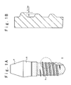
- Fig. 1A shows the structure of a dentistry implant according to the first embodiment of the present invention.
- a dentistry implant 1 is formed of material having bio-compatibility such as titanium or titanium alloy.
- the dentistry implant 1 is composed of an embedded section 3 embedded in jawbone 2, a gingiva penetrating section 5 to be located in gingiva, and a crowned section 6 which is located on the gingiva penetrating section 5.
- a thread is formed on the surface of the embedded section 3.
- the thread of an upper portion corresponding to a cortical bone section has a triangular cross section and the thread of a lower portion corresponding to a bone marrow section has a trapezoidal cross section.
- the thread of the upper portion is higher than the thread of the lower portion by a predetermined height, e.g., 0.1 mm.
- This height difference makes insertion of the implant easy.
- the heights of the thread portions are different in a step manner.
- the height of the thread may change in a continuous manner. That is, the height of the thread may be smallest in the lowermost portion and may become gradually larger toward the uppermost.
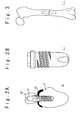
- Fig. 2A shows the structure of a dentistry implant 1' according to the second embodiment of the present invention.
- a dentistry implant 1' is formed of bio-compatible material such as titanium or titanium alloy, as in the first embodiment.
- the implant 1' is composed of an embedded section 3 embedded in jawbone 2, and a gingiva penetrating section 5 to be located in gingiva 23. There is no crowned section 6.
- a thread is formed on the whole surface of embedded section 3.
- a concave portion is formed inside of the gingiva penetrating section 5 such that an abutment 21 can be fit into the concave portion to form a crowned section 6.
- Fig. 2B shows the structure of a dentistry implant 1'' according to the third embodiment of the present invention.
- a dentistry implant is formed of bio-compatible material such as titanium or titanium alloy, as in the first embodiment.
- a thread is formed on only the upper portion of the embedded section 3 corresponding to the cortical bone section.
- a concave portion is formed inside of the gingiva penetrating section 5 such that an abutment 21 can be fit into the concave portion as a crowned section 6.
- Fig. 3 shows a use example of an implant 1''' according to the fourth embodiment of the present invention.
- the implant 1''' is embedded in femur sections to couple femur sections.
- the whole surface of the embedded section 3 of the implant main body member as an original implant is made rough and bioactive particles having osteo-conduction are stuck on the whole surface of the embedded section 3.
- the rough surface portion with stuck particles may be formed only below the upper portion of the thread portion.
- a step S2 the gingiva penetrating section 5 and the crowned section 6 of the main body member of titanium as an original implant 1 are masked not to be hit with grinding particles. Then, while the original implant is rotated, a primary sand blasting process is performed to the surface of the embedded section 3 of the original implant 1 using the grinding particles as the first sand blasting particles having an average grain diameter of 0.2 mm such as alumina ceramic particles, silica particles, and glass bead particles. As a result, the surface of the embedded section 3 of the original implant 1 is made rough.
- the roughness of the surface of the embedded section 3 is desirably in a range of 5 to 50 ⁇ m, and more desirably 15 to 50 ⁇ m, which fits to the size of osteocyte.
- ultrasonic cleaning is performed such that the grinding particles such as alumina ceramic particles, silica particles, and glass bead particles can be physically removed as much as possible.
- the primary sand blasting process is very effective when the original implant 1 is formed of hard material such as titanium-nickel alloy.
- bioactive sand blasting particles are prepared before a secondary sand blasting process is performed.
- the sintered hydroxylapatite particles are formed in the following manner.
- This method is called a precipitate method.
- Amorphous calcium phosphate is synthesized by adding phosphoric acid solution to calcium hydroxide suspension so as to be stoichiometric to hydroxylapatite.
- the amorphous calcium phosphate is dehydrated, filtered and dried up at the temperature of about 120 ° C. After that, it is crushed by a crushing machine, and then is calcined at the temperature of about 800 ° C for 1 hour. At this time, the rates of temperature increase and decrease are set to about 100 °C/Hr.
- polyvinyl alcohol aqueous solution of about 3 wt% is added to the powder which is obtained by this calcination so as to be equivalent.
- triethylene glycol of about 1 wt% is added.
- the mixture is dried up at the temperature of about 60° C together with the mortar, and then fine-ground to form powder.
- the fine-ground powder is classified using a sieve of the #200 mesh, and the classified powder under the sieve is used as granulation powder.
- the granulation powder obtained in this way is subjected to 1-axis formation at about 60 to 80 MPa to form a cake, and it is sintered at the temperature of about 1100 ° C.
- the sintered cake is ground and classified using #80 to 200 meshes.
- the sintered hydroxylapatite particles or pieces having the grain size of about 50 to 200 ⁇ m are obtained as the sand blasting particles.
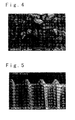
- the amorphous calcium phosphate is dehydrated, filtered and dried up at the temperature of about 120 ° C. After that, the amorphous calcium phosphate is sintered at the temperature of about 1250 ° C. Finally, the sintered amorphous calcium phosphate is crushed and classified using #16 to 280 meshes. Thus, the sintered hydroxylapatite particles having the grain size of about 50 ⁇ m to 1 mm are obtained as the sand blasting particles. The sand blasting particles or pieces thus obtained are shown in an electron microscope photograph of Fig. 4.
- the method of forming sintered tricalcium phosphate particles is substantially the same as the method of forming sintered hydroxylapatite (HAP) particles.
- phosphoric acid solution is added to be stoichiometric to tricalcium phosphate.
- the calcination temperature is set in a range of about 730 to 780 ° C and the sintering temperature is set in a range of about 950 to 1130 ° C, for example.
- the calcination temperature is set to about 750 ° C and the sintering temperature is set to about 1000 ° C, for example.
- the calcination temperature is set in a range of about 1100 to 1200 ° C and the sintering temperature is set in a range of about 1200 to 1280 ° C.
- the calcination temperature is set to about 1150 ° C and the sintering temperature is set to about 1250 ° C.
- a sintered cake is ground and classified using #80 to 200 meshes.
- the sintered tricalcium phosphate particles or pieces having the grain size of about 50 to 200 ⁇ m are obtained as the sand blasting particles.
- the secondary sand blasting process is performed while the original implant 1 which is subjected to the primary sand blasting process is rotated.
- the secondary sand blasting process is performed using calcium phosphate ceramic particles which are smaller than the grinding particles such as alumina ceramic particles, for example, using ⁇ tricalcium phosphate ceramic particles having an average grain diameter of 0.05 to 0.2 mm.
- the grinding particles such as the alumina ceramic particles are removed from the surface of the original implant 1.
- the original implant is obtained to have the titanium surface of a surface roughness which is determined based on the primary sand blasting process and to have ⁇ - tricalcium phosphate ceramic particles remained on the titanium surface.
- Fig. 5 shows an electron microscope photograph of the original implant 1 after the secondary sand blasting process is performed using tricalcium phosphate ceramic particles. It could be seen that the rough surface is formed on a part of the embedded section 3 of the original implant 1.
- Fig. 6 shows an electron microscope photograph of a part of the original implant 1 after the secondary sand blasting process is performed using the sintered tricalcium phosphate ceramic particles. It is shown in the center portion that the sintered tricalcium phosphate ceramic particle is tightly coupled to the embedded section 3 of the titanium original implant 1. That is, a tip portion of the sintered tricalcium phosphate ceramic particle is stuck into the embedded section 3 and the other portion is exposed from the embedded section 3.
- Fig. 7 shows an electron microscope photograph of a part of the original implant 1 after the secondary sand blasting process is performed using the sintered tricalcium phosphate ceramic particles.
- Fig. 8 shows the measuring result of the part of the original implant 1 by an electron probe microanalyzer (EPMA).
- EPMA electron probe microanalyzer
- white dots indicate the presence of calcium. Since calcium is detected from an upper left position, there is a portion of a thread section where calcium is not detected. However, it could be seen from Fig. 8 that calcium, i.e., hydroxylapatite or calcium phosphate exists on the entire surface of the embedded section 3 of the original implant 1.
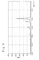
- Fig. 9 shows the measuring result of the original implant 1 by an X-ray diffractometer.
- the original implant 1 is subjected to the secondary sand blasting process using sintered ⁇ tricalcium phosphate ceramic particles.
- the peaks of ⁇ tricalcium phosphate appear together with peak of titanium.
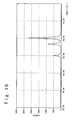
- the measuring result by the X-ray diffractometer after the original implant 1 is rinsed with 2N hydrochloric acid for one minute is shown in Fig. 10.
- the sintered ⁇ tricalcium phosphate ceramic particles dissolve and are lost.
- the secondary sand blasting particles such as the sintered hydroxylapatite (HAP) ceramic particles is broken and stick into the surface of the original implant 1.
- HAP sintered hydroxylapatite
- these fine particles are hydroxylapatite (HAP) or tricalcium phosphate having high bio-activity and are formed of the material which is absorbed by bone as in the present invention, these particles have osteo-conduction to contribute the formation of bone immediately after the implantation of the complete implant and to function to help the osteo-integration.
- HAP hydroxylapatite
- tricalcium phosphate having high bio-activity and are formed of the material which is absorbed by bone as in the present invention
- these particles have osteo-conduction to contribute the formation of bone immediately after the implantation of the complete implant and to function to help the osteo-integration.
- the secondary sand blasting process is performed about twice of the primary sand blasting processing time, i.e., about 1 to 2 minutes. For this reason, the bioinert grinding particles such as alumina particles can be completely removed, although depending on conditions of the sand blasting processes.
- the material of the particles used in the secondary sand blasting process is desirably sintered substances of hydroxylapatite, ⁇ - tricalcium phosphate, ⁇ -tricalcium phosphate, tetra-calcium phosphate or the like, a single substance of amorphous calcium phosphate, monetite, brushite, 45S4 glass, other bioactive glass or the like, or these mixtures.
- the blasting pressure is set to a slightly higher value than the usual sand blasting processes when the sintered calcium phosphate ceramic particles or the like are used.
- the material of the particles is desirably ⁇ -tricalcium phosphate, ⁇ -tricalcium phosphate, or bioactive glass such as 45S5 glass which have osteo-conduction and are completely absorbed in a living body.
- the primary sand blasting process is performed, eutictic particles with hydroxylapatite are formed, or mixture particles with hydroxylapatite are formed.
- alumina ceramic particles and ⁇ -tricalcium phosphate ceramic particles can be chosen in size to have various diameters, for example, of about 0.1 to 0.5 mm in case of the primary sand blasting process, and about 0.01 to 0.1 mm in case of the secondary sand blasting process.
- hydrothermal processing is performed to the original implant 1 which is subjected to the secondary sand blasting process.
- the hydrothermal processing is performed in ⁇ -tricalcium phosphate suspension in the temperature of 130° C for 60 hours such that the titanium surface of the original implant 1 is converted into a titanium oxide surface.
- the surfaces of the particles are converted into hydroxylapatite layers.
- a dentistry implant is obtained in which metal allergy is extremely suppressed and which has the surface of a high bio-compatibility.
- the temperature and time of the above hydrothermal processing can be selected suitably in accordance with the condition.
- Various kinds of pseudo-humor such as Hank's balanced salt solution, various kinds of suspension or saturated solution of calcium phosphate, and mixture solution of them can be used for the hydrothermal processing.
- Different titanium oxide layers are formed on the surface of the original implant depending upon the processing temperature, the processing time and the kind of solution.
- the processing temperature is in a range of about 60 to 200 ° C and the processing time is in a range of about 24 Hr to 48 Hr.
- the calcium phosphate ceramic particles and so on which have been remained on the surface of the original implant in the blasting process are converted into the hydroxylapatite in the whole particles or the surfaces under these process conditions. As a result, they become stable calcium phosphate ceramics.
- the thirdly sand blasting process is performed with a low blasting pressure in a range of about 0.2 to 0.3 Pa.
- the thirdly sand blasting particles formed of, for example, ⁇ -tricalcium phosphate, ⁇ -tricalcium phosphate, and bioactive glass and so on which have high osteo-conduction.
- the blade-shaped implant formed of titanium is obtained to have an initial osteo-conduction, to have suitable surface roughness for bone, and contain a little amount of 45S5 glass 7.
- the gingiva penetrating section 5 and the crowned section 6 are masked such that the blasting particles do not hit.
- the secondary sand blasting process may be performed to the gingiva penetrating section 5 and the crowned section 6.
- the original implant is not rotated. However, it may be rotated during the sand blasting process as described above.
- a titanium implant original implant 1 of a cylindrical shape with the diameter of 4 mm is rotated with the rotation speed of 100 rpm.
- the primary sand blasting process is performed to the embedded section 3 with the blasting pressure of 0.4 Pa using alumina ceramic particles with an average grain diameter of 0.2mm.
- the gingiva penetrating section 5 and the crowned section 6 is masked such that the alumina ceramic blasting particles do not hit the sections.
- the secondary sand blasting process is performed with the blasting pressure of 0.7 Pa using the mixture particles in which 45S5 glass particles, ⁇ -tricalcium phosphate ceramic particles and sintered hydroxylapatite ceramic particles are mixed with the ratio of 1 : 1 : 1 and which have the average grain diameter of 0.05mm.
- the final implant formed of titanium is obtained which has the surface 8 of a suitable surface roughness to bone.
- the final implant has an osteo-conduction, and contains bioactive glass particles and calcium phosphate ceramic particles 9 remained on the surface and finally completely absorbed into the living body.
- the primary sand blasting process is performed to the embedded section of a blade implant formed of alloy of titanium and nickel with the blasting pressure of 0.4 Pa, using alumina ceramic particles with the average grain diameter of 0.2mm.
- the gingiva penetrating section 5 and the crowned section 6 are masked such that the blasting particles do not hit the masked sections.
- the secondary sand blasting process is performed with the blasting pressure of 0.7 Pa using ⁇ -tricalcium phosphate ceramic particles 10 having the average grain diameter of 0.05mm.
- a hydrothermal process is performed in ⁇ - tricalcium phosphate suspension at the temperature of 130 ° C.
- a titanium oxide film 11 is formed on the titanium surface, and hydroxylapatite layers 12 is formed on the remaining tricalcium phosphate particle surfaces. In this case, some of the tricalcium phosphate particles are converted into hydroxylapatite particles.
- the thirdly sand blasting process is performed with the blasting pressure of 0.3 Pa using ⁇ -tricalcium phosphate ceramic particles.
- the blade implant formed of titanium-nickel alloy is obtained which has a suitable surface roughness to bone.
- the blade implant has a stable titanium oxide layer formed on the titanium surface, and contains hydroxylapatite of a high bio-compatibility.
- ⁇ -tricalcium phosphate having an osteo-conduction remains on the surface.
- the "bioactive” material implies material to which the living body does not indicate rejection symptoms, which can chemically couple to bone by bio-integration, and which has bio-conduction which is capability of attracting osteoblasts and promoting formation of new bone.
- the particles used in the present invention have "bio-activity" to realize bio-integration. Therefore, the bioactive particles does not prevent osteo-integration between the implant of titanium and bone but helps realization of the osteo-integration.
- the present invention is not limited to them.
- the present invention can be applied to an implant coupling bones each other, as shown in Fig. 3.
- at least one of the sand blasting processes is applied to at least a part of the implant.
- the whole of original implant is formed of titanium or titanium alloy.
- the original implant may be formed of stainless and platinum and only a part of the original implant corresponding to the embedded section may be formed titanium, titanium alloy or titanium oxide in surface or whole.
- the original implant may be formed to have a calcium phosphate ceramic coating layer in part or whole.
- the implant has the crowned section.
- the implant may not have the crowned section as shown in Figs. 2A and 2B. In this case, an abutment is attached when the implant is inserted.
- an implant formed of titanium or titanium alloy is subjected to sand blasting process(es) using particles formed of sintered hydroxylapatite, sintered tricalcium phosphate, or bioactive glass or the mixture of them.
- the above materials other than the sintered hydroxylapatite are the material absorbed in the bone or substituted by the bone.
- the implant is fixed to the bone in the early step after it is embedded in the bone. Also, after the absorption of the material, the implant is provided which is coupled to the bone with stable osteo-integration.
- the implant surface has a predetermined surface roughness.
- the secondary blasting process is performed once again using the blasting particles formed of bioactive glass, or sintered hydroxylapatite, sintered tricalcium phosphate or a mixture of them.
- titanium or titanium alloy i.e., alloy of titanium and material such as nickel, aluminum, vanadium, it is difficult to form a rough surface of titanium or titanium alloy with only the blasting particles of calcium phosphate ceramics and so on.
- the primary sand blasting process it become possible to efficiently form the rough surface on titanium or titanium alloy surface.
- the secondary sand blasting process is performed for a longer time than in the primary sand blasting process, if the particles used in the secondary sand blasting process are smaller than grinding particles used in the primary sand blasting process. As a result, the grinding particles of alumina ceramics and so on can be removed.
- the titanium or titanium alloy surface having a rough surface by calcium phosphate ceramics, bioactive glass and so on is subjected to the hydrothermal process at the temperature of about 60 to 200 ° C in various types of pseudo-humor and tricalcium phosphate saturation solution or these mixture solution.
- a stable layer of the titanium oxide film is provided for the blasted titanium surface.
- a hydroxylapatite layer is formed on the remaining calcium phosphate ceramic blasting particle surface.
- the thin stable layer mainly formed of titanium oxide on the titanium or titanium alloy surface has a function to promote osteo-integration.
- the surface of the calcium phosphate ceramic particles remained in the titanium or titanium alloy surface becomes a stable hydroxylapatite layer. In this manner, the implant is provided which joins to bone in the earlier step.
- the thirdly sand blasting process may be performed to the implant surface, using the particles formed of bioactive glass, sintered hydroxylapatite and tricalcium phosphate, or mixture of them. As a result, the whole surface or bulk is made to have a rough surface. Also, the bioactive particles are stuck into the oxide film layer to allow enough bone formation to be promoted. Such an implant is provided.
- a portion of titanium or titanium alloy of the implant which contacts bone is subjected to the sand blasting process with particles such as bioactive glass.
- the portion of titanium or titanium alloy is subjected to the primary sand blasting process with the hard particles of alumina ceramics and so on and the secondary sand blasting process with the particles of calcium phosphate ceramics and so on.
- the portion of titanium or titanium alloy is subjected to a hydrothermal process such that the titanium surface is converted into titanium oxide and a calcium phosphate ceramics part is converted into hydroxylapatite.
- the sand blasting process is further performed to the titanium oxide surface using secondary blasting material.
- the implant can be obtained to have the titanium surface which contains the particles which contribute to form bone and have a high bio-compatibility. Also, by this method, it is made possible to provide a stable and safe titanium or titanium alloy implant with a low price.
Abstract

Description
- The present invention relates to an implant such as an implant embedded in bones and a dentistry implant and a method of manufacturing the same, and more particularly to an implant with bioactive particles stuck and a method of manufacturing the same.
- Titanium or titanium alloy is generally used as material of implants such as an implant embedded in bone and a dentistry implant at present. This is because when the implant is installed, the material of the implants has a state called "osteo-integration" in which the implant directly contacts bone. The osteo-integration implies the state in which there is no connective tissue between the bone and the implant.
If other material is used, there is a case that the osteo-integration is not realized and a fibrous connective tissue is intervened between the implant and the bone. For this reason, the whole implant is finally covered by the fibrous connective tissue so that the fluctuation of the implant starts. Therefore, the implant must be pulled out. - In order to further increase the effect of the osteo-integration, it could be considered that the surface of the implant is made rough. There could be various methods of making the implant surface rough. For instance, as one of the methods, there is a method in which beads of metal titanium are sprayed in plasma such that the surface of the implant has many hemispheric titanium (Ti) protrusions in a microscope level and the surface area of the implant is increased. This technique also makes it possible to increase the bio-compatibility of the implant with bone cells. Another method is a sand blasting method using grinding particles of alumina and so on. In this method, the surface area of the implant is increased to reflect the size of the grinding particles. Also, an anchor effect is achieved because bone enters into concave portions of the implant.
- Also, the implant that a hydroxylapatite (HAP) layer is coated on the surface of the implant of titanium is commercially available. In such an implant, the connection state between the bone and the hydroxylapatite layer is called bio-integration, and it is said that the implant and the bone are chemically coupled to each other. The bio-integration is stronger than the osteo-integration in coupling strength. In a method of coating the hydroxylapatite layer, a powder of hydroxylapatite is adhered to the surface of the implant by a plasma thermal spraying method and so on. Because the hydroxylapatite layer of the implant is an aggregation of powder, the surface of the implant has portions with very small unevenness and has the above-mentioned anchor effect.
- However, there are the following problems in the above-mentioned conventional implants. In the implant having the surface where the beads of titanium are sprayed in the plasma, because the plasma spraying method is the very advanced technique which requires high cost, the final implant cost becomes very expensive. On the other hand, it is possible to manufacture with low cost the implant having the surface which is subjected to the sand blasting process using the alumina grinding particles. However, there is a problem in that it is difficult to remove the adherent alumina grinding particles so that bioinert alumina particles are remained on the surface of the implant. Therefore, the formation of osteo-integration is prevented.
- Further, it is in the present situation that there is little implant that the hydroxylapatite layer is coated as the commercially available products. The reason is that advanced technique is needed in the hydroxylapatite coating and it is costly. Also, the reason is that the implant having a titanium surface is finally superior to the implant having the hydroxylapatite layer, because bone coupling state is destructed through delamination of the hydroxylapatite coating layer.
- In view of these points, the inventors of the present application performed various types of study and experiment as for the implant surface which had suitable roughness to bone and which could realize osteo-integration. As a result, the inventors found out a method of forming an implant having a stable surface, in which the implant had the good property of the implant having the titanium surface and the good property of the implant having the HAP coated surface. The implant can be simply manufactured from bioactive particles having osteo-conduction with low cost without bioinert impurity such as alumina particles.
- Therefore, an object of the present invention is to provide an implant which has the good property of an implant having a titanium surface and the good property of an implant having a hydroxylapatite coated surface, and a method of manufacturing the same.
- Another object of the present invention is to provide a method of manufacturing bioactive blasting particles.
- Still another object of the present invention is to provide an implant having bioactive particles on its surface and a method of manufacturing the same.
- In order to achieve an aspect of the present invention, an implant includes a main body member having bio-compatibility, and particles formed of bioactive material and dispersedly provided at a processed surface of at least a portion of the main body member such that each of the particles has a part embedded in the processed surface and a part protruding from the processed surface.
- It is desirable that the processed surface has a surface roughness in a range of 5 to 50 µm, and more desirably, 15 to 30 µm. Also, it is desirable that at least a part of the processed surface includes a surface formed of one of titanium, titanium alloy and titanium oxide.
- The portion corresponding to the processed surface includes a thread portion provided on the entire of the portion. In this case, the thread portion is low in height in a region near an end of the portion and is high in height in a region apart from the end of the portion. Alternatively, the portion corresponding to processed surface may include a thread portion provided in a region apart from an end of the portion.
- Also, the particles have osteo-conduction. For example, the particles are formed of a material selected from among a group consisting of sintered substances of hydroxylapatite, α-tricalcium phosphate, β-tricalcium phosphate, tetra-calcium phosphate, a single substance of amorphous calcium phosphate, monetite, brushite, 45S4 glass, and a mixture of them. Each of at least particles of the particles may have a hydroxylapatite layer at the protruding part.
- In order to achieve another aspect of the present invention, a method of manufacturing an implant, includes the steps of:
- providing a main body member having biocompatibility; and
- dispersedly providing particles formed of bioactive material at a processed surface of at least a portion of the main body member such that each of the particles has a part embedded in the processed surface and a part protruding from the processed surface.
-
- At least a part of the processed surface includes a surface formed of one of titanium and titanium alloy. Also, the particles have osteo-conduction. For example, the particles are formed of material selected from among a group consisting of sintered substances of hydroxylapatite, α-tricalcium phosphate, β-tricalcium phosphate, tetra-calcium phosphate, a single substance of amorphous calcium phosphate, monetite, brushite, 45S4 glass, and a mixture of them.
- The dispersion of the particles may be achieved by performing a primary sand blasting process to the processed surface using the particles. In this case, the primary sand blasting process is performed while the main body member is rotated.
- In order to achieve still another aspect of the present invention, a method of manufacturing an implant, includes the steps of:
- providing a main body member having bio-compatibility;
- making a processed surface of at least a portion of the main body member rough; and
- dispersedly providing particles formed of bioactive material at the processed surface such that each of the particles has a part embedded in the processed surface and a part protruding from the processed surface. The processed surface has a surface roughness in a range of 5 to 50 µm.
-
- In order to achieve yet still another aspect of the present invention, a method of manufacturing an implant, includes the steps of:
- providing a main body member having bio-compatibility;
- dispersedly providing particles formed of bioactive material including calcium phosphate at a processed surface of at least a portion of the main body member formed of titanium or titanium alloy such that each of the particles has a part embedded in the processed surface and a part protruding from the processed surface; and
- forming a titanium oxide layer on the processed surface and a hydroxylapatite layer on a surface of each of the particles.
-
- The formation titanium oxide layer may be achieved by performing hydrothermal process to the processed surface at least. In this case, a solution used in the hydrothermal process is selected from among a group consisting of pseudo-humor, suspension or saturated solution of calcium phosphate, and mixture solution of them.
- The method may further include the step of performing a secondary sand blasting process to the processed surface using secondary blasting particles formed of bioactive material such that each of the secondary blasting particles has a part embedded in the processed surface and a part protruding from the processed surface.
- In this case, the particles are formed from the following steps. That is, the step of forming the particles includes:
- producing amorphous calcium phosphate by a precipitate method by adding phosphoric acid solution to calcium hydroxide suspension;
- sintering the amorphous calcium phosphate at a predetermined temperature; and
- crushing the sintered amorphous calcium phosphate to select the sintered hydroxylapatite particles using a mesh.
-
-
- Fig. 1A is a front view of a dentistry implant according to a first embodiment of the present invention;
- Fig. 1B is a partially expanded vertical cross sectional view of the dentistry implant shown in Fig. 1A;
- Fig. 2A is a diagram illustrating an example in which a dentistry implant according to a second embodiment of the present invention is applied;
- Fig. 2B is a diagram illustrating an example in which a dentistry implant according to a third embodiment of the present invention is applied;
- Fig. 3 is a diagram illustrating an example in which an implant according to a fourth embodiment of the present invention is applied to femur.
- Fig. 4 is a diagram illustrating an electron microscope photograph of the surface of an implant after a sand blasting process is performed;
- Fig. 5 is a diagram illustrating an electron microscope photograph of sand blasting particles which have osteo-conduction and which are used for the sand blasting process;
- Fig. 6 is a diagram of an electron microscope photograph illustrating the state in which a sand blasting particles is stuck into a main body member as an original implant;
- Fig. 7 is a diagram illustrating an electron microscope photograph of the surface of an implant after a sand blasting process is performed;
- Fig. 8 is a diagram illustrating a measuring result of a portion shown in Fig. 7 by an EPMA;
- Fig. 9 is a chart obtained as a measuring result of the original implant by an X-ray diffractometer after a sand blasting process is performed using bioactive β-tricalcium phosphate (TCP) particles having a main peak at about 2 = 31.0° ;
- Fig. 10 is a chart obtained as a measuring result of the original implant by the X-ray diffractometer after the original implant used for the measurement shown in Fig. 9 is rinsed with 2N hydrochloric acid for one minute;
- Fig. 11 is a flow chart to explain a method of manufacturing an implant of the present invention;
- Fig. 12 is a schematic front view of a blade-type implant when the manufacturing method is applied to the blade-type implant;
- Fig. 13 is a schematic front view of a dentistry implant when the manufacturing method is applied to the dentistry implant; and
- Fig. 14 is a cross sectional view of an implant to which the manufacturing method is applied.
-
- The implant of the present invention will be described below in detail with reference to the accompanying drawings.
- Fig. 1A shows the structure of a dentistry implant according to the first embodiment of the present invention. Referring to Fig. 1A, a
dentistry implant 1 is formed of material having bio-compatibility such as titanium or titanium alloy. Thedentistry implant 1 is composed of an embeddedsection 3 embedded injawbone 2, agingiva penetrating section 5 to be located in gingiva, and a crownedsection 6 which is located on thegingiva penetrating section 5. A thread is formed on the surface of the embeddedsection 3. As shown in Fig. 1B, the thread of an upper portion corresponding to a cortical bone section has a triangular cross section and the thread of a lower portion corresponding to a bone marrow section has a trapezoidal cross section. Therefore, the thread of the upper portion is higher than the thread of the lower portion by a predetermined height, e.g., 0.1 mm. This height difference makes insertion of the implant easy. In this example, the heights of the thread portions are different in a step manner. However, the height of the thread may change in a continuous manner. That is, the height of the thread may be smallest in the lowermost portion and may become gradually larger toward the uppermost. - Fig. 2A shows the structure of a dentistry implant 1' according to the second embodiment of the present invention. Referring to Fig. 2A, a dentistry implant 1' is formed of bio-compatible material such as titanium or titanium alloy, as in the first embodiment. The implant 1' is composed of an embedded
section 3 embedded injawbone 2, and agingiva penetrating section 5 to be located ingingiva 23. There is no crownedsection 6. A thread is formed on the whole surface of embeddedsection 3. A concave portion is formed inside of thegingiva penetrating section 5 such that anabutment 21 can be fit into the concave portion to form a crownedsection 6. - Fig. 2B shows the structure of a dentistry implant 1'' according to the third embodiment of the present invention. Referring to Fig. 2B, a dentistry implant is formed of bio-compatible material such as titanium or titanium alloy, as in the first embodiment. Unlike the implant shown in Fig. 2A, in the implant in the third embodiment, a thread is formed on only the upper portion of the embedded
section 3 corresponding to the cortical bone section. A concave portion is formed inside of thegingiva penetrating section 5 such that anabutment 21 can be fit into the concave portion as a crownedsection 6. - Fig. 3 shows a use example of an implant 1''' according to the fourth embodiment of the present invention. In this embodiment, the implant 1''' is embedded in femur sections to couple femur sections.
- In the implants shown in Figs. 1A, 2A and 2B, the whole surface of the embedded
section 3 of the implant main body member as an original implant is made rough and bioactive particles having osteo-conduction are stuck on the whole surface of the embeddedsection 3. However, the rough surface portion with stuck particles may be formed only below the upper portion of the thread portion. - Referring to Fig. 11, a method of manufacturing of the
implant 1 in the first embodiment will be described below. - In a step S2, the
gingiva penetrating section 5 and the crownedsection 6 of the main body member of titanium as anoriginal implant 1 are masked not to be hit with grinding particles. Then, while the original implant is rotated, a primary sand blasting process is performed to the surface of the embeddedsection 3 of theoriginal implant 1 using the grinding particles as the first sand blasting particles having an average grain diameter of 0.2 mm such as alumina ceramic particles, silica particles, and glass bead particles. As a result, the surface of the embeddedsection 3 of theoriginal implant 1 is made rough. In this case, the roughness of the surface of the embeddedsection 3 is desirably in a range of 5 to 50 µm, and more desirably 15 to 50 µm, which fits to the size of osteocyte. After that, ultrasonic cleaning is performed such that the grinding particles such as alumina ceramic particles, silica particles, and glass bead particles can be physically removed as much as possible. The primary sand blasting process is very effective when theoriginal implant 1 is formed of hard material such as titanium-nickel alloy. - Next, in a step S4, bioactive sand blasting particles are prepared before a secondary sand blasting process is performed.
- When sintered hydroxylapatite particles are used as the second sand blasting particles, the sintered hydroxylapatite particles are formed in the following manner. This method is called a precipitate method. Amorphous calcium phosphate is synthesized by adding phosphoric acid solution to calcium hydroxide suspension so as to be stoichiometric to hydroxylapatite. The amorphous calcium phosphate is dehydrated, filtered and dried up at the temperature of about 120 ° C. After that, it is crushed by a crushing machine, and then is calcined at the temperature of about 800 ° C for 1 hour. At this time, the rates of temperature increase and decrease are set to about 100 °C/Hr. Next, polyvinyl alcohol aqueous solution of about 3 wt% is added to the powder which is obtained by this calcination so as to be equivalent. Further, triethylene glycol of about 1 wt% is added. Then, it is well mixed and kneaded by an automatic mortar. The mixture is dried up at the temperature of about 60° C together with the mortar, and then fine-ground to form powder. Then, the fine-ground powder is classified using a sieve of the #200 mesh, and the classified powder under the sieve is used as granulation powder. The granulation powder obtained in this way is subjected to 1-axis formation at about 60 to 80 MPa to form a cake, and it is sintered at the temperature of about 1100 ° C. Finally, the sintered cake is ground and classified using #80 to 200 meshes. Thus, the sintered hydroxylapatite particles or pieces having the grain size of about 50 to 200 µm are obtained as the sand blasting particles.
- Alternatively, the amorphous calcium phosphate is dehydrated, filtered and dried up at the temperature of about 120 ° C. After that, the amorphous calcium phosphate is sintered at the temperature of about 1250 ° C. Finally, the sintered amorphous calcium phosphate is crushed and classified using #16 to 280 meshes. Thus, the sintered hydroxylapatite particles having the grain size of about 50 µm to 1 mm are obtained as the sand blasting particles. The sand blasting particles or pieces thus obtained are shown in an electron microscope photograph of Fig. 4.
- The method of forming sintered tricalcium phosphate particles is substantially the same as the method of forming sintered hydroxylapatite (HAP) particles. However, in the step of synthesizing amorphous calcium phosphate, phosphoric acid solution is added to be stoichiometric to tricalcium phosphate. Also, if the crystal structure of target particles is β tricalcium phosphate, the calcination temperature is set in a range of about 730 to 780 ° C and the sintering temperature is set in a range of about 950 to 1130 ° C, for example. Preferably, the calcination temperature is set to about 750 ° C and the sintering temperature is set to about 1000 ° C, for example. On the other hand, if the crystal structure of target particles is α tricalcium phosphate, the calcination temperature is set in a range of about 1100 to 1200 ° C and the sintering temperature is set in a range of about 1200 to 1280 ° C. Preferably, the calcination temperature is set to about 1150 ° C and the sintering temperature is set to about 1250 ° C. Finally, a sintered cake is ground and classified using #80 to 200 meshes. Thus, the sintered tricalcium phosphate particles or pieces having the grain size of about 50 to 200 µm are obtained as the sand blasting particles.
- Next, in a step S6, the secondary sand blasting process is performed while the
original implant 1 which is subjected to the primary sand blasting process is rotated. The secondary sand blasting process is performed using calcium phosphate ceramic particles which are smaller than the grinding particles such as alumina ceramic particles, for example, using α tricalcium phosphate ceramic particles having an average grain diameter of 0.05 to 0.2 mm. As a result, the grinding particles such as the alumina ceramic particles are removed from the surface of theoriginal implant 1. In this case, the original implant is obtained to have the titanium surface of a surface roughness which is determined based on the primary sand blasting process and to have α- tricalcium phosphate ceramic particles remained on the titanium surface. - Fig. 5 shows an electron microscope photograph of the
original implant 1 after the secondary sand blasting process is performed using tricalcium phosphate ceramic particles. It could be seen that the rough surface is formed on a part of the embeddedsection 3 of theoriginal implant 1. - Fig. 6 shows an electron microscope photograph of a part of the
original implant 1 after the secondary sand blasting process is performed using the sintered tricalcium phosphate ceramic particles. It is shown in the center portion that the sintered tricalcium phosphate ceramic particle is tightly coupled to the embeddedsection 3 of the titaniumoriginal implant 1. That is, a tip portion of the sintered tricalcium phosphate ceramic particle is stuck into the embeddedsection 3 and the other portion is exposed from the embeddedsection 3. - Fig. 7 shows an electron microscope photograph of a part of the
original implant 1 after the secondary sand blasting process is performed using the sintered tricalcium phosphate ceramic particles. Fig. 8 shows the measuring result of the part of theoriginal implant 1 by an electron probe microanalyzer (EPMA). In Fig. 8, white dots indicate the presence of calcium. Since calcium is detected from an upper left position, there is a portion of a thread section where calcium is not detected. However, it could be seen from Fig. 8 that calcium, i.e., hydroxylapatite or calcium phosphate exists on the entire surface of the embeddedsection 3 of theoriginal implant 1. - Fig. 9 shows the measuring result of the
original implant 1 by an X-ray diffractometer. Theoriginal implant 1 is subjected to the secondary sand blasting process using sintered β tricalcium phosphate ceramic particles. As seen from Fig. 9, the peaks of β tricalcium phosphate appear together with peak of titanium. The calcium phosphate has the main peak at about 2 = 31 degrees. The measuring result by the X-ray diffractometer after theoriginal implant 1 is rinsed with 2N hydrochloric acid for one minute is shown in Fig. 10. As seen from Fig. 10, the sintered β tricalcium phosphate ceramic particles dissolve and are lost. - When being blasted toward the
original implant 1 to reach the surface of theoriginal implant 1, the secondary sand blasting particles such as the sintered hydroxylapatite (HAP) ceramic particles is broken and stick into the surface of theoriginal implant 1. As a result, a part of the broken particle is embedded into theoriginal implant 1 and another portion protrudes from the surface of theoriginal implant 1. These sticking fine particles are not removed by usual ultrasonic cleaning and remained on the surface. If these remained fine particles are alumina, they are recognized as bioinert material in the living body so that osteo-integration is obstructed. However, when these fine particles are hydroxylapatite (HAP) or tricalcium phosphate having high bio-activity and are formed of the material which is absorbed by bone as in the present invention, these particles have osteo-conduction to contribute the formation of bone immediately after the implantation of the complete implant and to function to help the osteo-integration. - Also, it is desirable that when the primary sand blasting process is performed for about 30 seconds to 1 minute, the secondary sand blasting process is performed about twice of the primary sand blasting processing time, i.e., about 1 to 2 minutes. For this reason, the bioinert grinding particles such as alumina particles can be completely removed, although depending on conditions of the sand blasting processes.
- The material of the particles used in the secondary sand blasting process is desirably sintered substances of hydroxylapatite, α - tricalcium phosphate, β-tricalcium phosphate, tetra-calcium phosphate or the like, a single substance of amorphous calcium phosphate, monetite, brushite, 45S4 glass, other bioactive glass or the like, or these mixtures.
- Because sintered calcium phosphate ceramic particles are soft compared with a grit of alumina or glass which are used in usual sand blasting processes to metal, it is desirable that the blasting pressure is set to a slightly higher value than the usual sand blasting processes when the sintered calcium phosphate ceramic particles or the like are used.
- Considering the remaining effect of the secondary sand blasting process particles such as calcium phosphate ceramics and so on, the material of the particles is desirably α-tricalcium phosphate, β-tricalcium phosphate, or bioactive glass such as 45S5 glass which have osteo-conduction and are completely absorbed in a living body. However, because it is relatively difficult to form hard particles from a single phase of them, it could be considered that the primary sand blasting process is performed, eutictic particles with hydroxylapatite are formed, or mixture particles with hydroxylapatite are formed.
- It should be noted that the above alumina ceramic particles and α-tricalcium phosphate ceramic particles can be chosen in size to have various diameters, for example, of about 0.1 to 0.5 mm in case of the primary sand blasting process, and about 0.01 to 0.1 mm in case of the secondary sand blasting process.
- Referring to Fig. 11, in a next step S8, hydrothermal processing is performed to the
original implant 1 which is subjected to the secondary sand blasting process. The hydrothermal processing is performed in α-tricalcium phosphate suspension in the temperature of 130° C for 60 hours such that the titanium surface of theoriginal implant 1 is converted into a titanium oxide surface. On the other hand, in the portion where the secondary α-tricalcium phosphate ceramic particles remain, the surfaces of the particles are converted into hydroxylapatite layers. In this manner, a dentistry implant is obtained in which metal allergy is extremely suppressed and which has the surface of a high bio-compatibility. It should be noted that the temperature and time of the above hydrothermal processing can be selected suitably in accordance with the condition. - Various kinds of pseudo-humor such as Hank's balanced salt solution, various kinds of suspension or saturated solution of calcium phosphate, and mixture solution of them can be used for the hydrothermal processing. Different titanium oxide layers are formed on the surface of the original implant depending upon the processing temperature, the processing time and the kind of solution. However, it is preferable that the processing temperature is in a range of about 60 to 200 ° C and the processing time is in a range of about 24 Hr to 48 Hr. The calcium phosphate ceramic particles and so on which have been remained on the surface of the original implant in the blasting process are converted into the hydroxylapatite in the whole particles or the surfaces under these process conditions. As a result, they become stable calcium phosphate ceramics.
- Referring to Fig. 11 again, in a next step S10, the thirdly sand blasting process is performed with a low blasting pressure in a range of about 0.2 to 0.3 Pa. As a result, on the surface of the original implant which is subjected to the secondary sand blasting process or the hydrothermal processing in addition to it, the thirdly sand blasting particles formed of, for example, α-tricalcium phosphate, β-tricalcium phosphate, and bioactive glass and so on which have high osteo-conduction.
- Next, specific examples 1 to 3 of the present invention will be described. However, the present invention is not limited to these examples.
- Only the secondary sand blasting process is performed to the embedded
section 3 of the blade-shapedoriginal implant 1 of titanium with the blasting pressure of 0.7 Pa using 45S5 glass particles with an average grain diameter of 0.1mm. By this, as shown in Fig. 12, the blade-shaped implant formed of titanium is obtained to have an initial osteo-conduction, to have suitable surface roughness for bone, and contain a little amount of 45S5 glass 7. In this case, thegingiva penetrating section 5 and the crownedsection 6 are masked such that the blasting particles do not hit. However, the secondary sand blasting process may be performed to thegingiva penetrating section 5 and the crownedsection 6. In this example, the original implant is not rotated. However, it may be rotated during the sand blasting process as described above. - A titanium implant
original implant 1 of a cylindrical shape with the diameter of 4 mm is rotated with the rotation speed of 100 rpm. The primary sand blasting process is performed to the embeddedsection 3 with the blasting pressure of 0.4 Pa using alumina ceramic particles with an average grain diameter of 0.2mm. In this case, thegingiva penetrating section 5 and the crownedsection 6 is masked such that the alumina ceramic blasting particles do not hit the sections. After ultrasonic cleaning and drying, the secondary sand blasting process is performed with the blasting pressure of 0.7 Pa using the mixture particles in which 45S5 glass particles, β-tricalcium phosphate ceramic particles and sintered hydroxylapatite ceramic particles are mixed with the ratio of 1 : 1 : 1 and which have the average grain diameter of 0.05mm. Thus, as shown in Fig. 13, the final implant formed of titanium is obtained which has thesurface 8 of a suitable surface roughness to bone. The final implant has an osteo-conduction, and contains bioactive glass particles and calcium phosphate ceramic particles 9 remained on the surface and finally completely absorbed into the living body. - The primary sand blasting process is performed to the embedded section of a blade implant formed of alloy of titanium and nickel with the blasting pressure of 0.4 Pa, using alumina ceramic particles with the average grain diameter of 0.2mm. In this case, the
gingiva penetrating section 5 and the crownedsection 6 are masked such that the blasting particles do not hit the masked sections. - After ultrasonic cleaning and drying, the secondary sand blasting process is performed with the blasting pressure of 0.7 Pa using α-tricalcium phosphate
ceramic particles 10 having the average grain diameter of 0.05mm. After that, a hydrothermal process is performed in α- tricalcium phosphate suspension at the temperature of 130 ° C. As a result, atitanium oxide film 11 is formed on the titanium surface, and hydroxylapatite layers 12 is formed on the remaining tricalcium phosphate particle surfaces. In this case, some of the tricalcium phosphate particles are converted into hydroxylapatite particles. - Further, the thirdly sand blasting process is performed with the blasting pressure of 0.3 Pa using α -tricalcium phosphate ceramic particles. As a result, as shown in Fig. 14, the blade implant formed of titanium-nickel alloy is obtained which has a suitable surface roughness to bone. Also, the blade implant has a stable titanium oxide layer formed on the titanium surface, and contains hydroxylapatite of a high bio-compatibility. As a result, α-tricalcium phosphate having an osteo-conduction remains on the surface.
- In the present invention, it should be noted that the "bioactive" material implies material to which the living body does not indicate rejection symptoms, which can chemically couple to bone by bio-integration, and which has bio-conduction which is capability of attracting osteoblasts and promoting formation of new bone. The particles used in the present invention have "bio-activity" to realize bio-integration. Therefore, the bioactive particles does not prevent osteo-integration between the implant of titanium and bone but helps realization of the osteo-integration.
- Also, in the above embodiments and examples, only the dentistry implant is described. However, the present invention is not limited to them. The present invention can be applied to an implant coupling bones each other, as shown in Fig. 3. In this case, at least one of the sand blasting processes is applied to at least a part of the implant. Specifically, it is desirable for the present invention to be applied to the whole implant.
- Further, in the above embodiments and examples, the whole of original implant is formed of titanium or titanium alloy. However, the original implant may be formed of stainless and platinum and only a part of the original implant corresponding to the embedded section may be formed titanium, titanium alloy or titanium oxide in surface or whole. Alternatively, the original implant may be formed to have a calcium phosphate ceramic coating layer in part or whole.
- In addition, in the above example, the implant has the crowned section. However, the implant may not have the crowned section as shown in Figs. 2A and 2B. In this case, an abutment is attached when the implant is inserted.
- In the present invention, an implant formed of titanium or titanium alloy is subjected to sand blasting process(es) using particles formed of sintered hydroxylapatite, sintered tricalcium phosphate, or bioactive glass or the mixture of them. The above materials other than the sintered hydroxylapatite are the material absorbed in the bone or substituted by the bone.
- These particles stuck into the implant surface through the blasting process prompts formation of new bone around the implant immediately after the implant is embedded in the bone. The material of the particles is gradually absorbed during the formation of new bone, then is completely substituted by the new bone, and finally, the osteo-integration is realized. Thus, the implant is fixed to the bone in the early step after it is embedded in the bone. Also, after the absorption of the material, the implant is provided which is coupled to the bone with stable osteo-integration.
- Also, after the primary blasting process is performed to the surface of the original implant formed of titanium or titanium alloy using the particles formed of hard material such as alumina ceramics and silica. As a result, the implant surface has a predetermined surface roughness. The secondary blasting process is performed once again using the blasting particles formed of bioactive glass, or sintered hydroxylapatite, sintered tricalcium phosphate or a mixture of them. In titanium or titanium alloy, i.e., alloy of titanium and material such as nickel, aluminum, vanadium, it is difficult to form a rough surface of titanium or titanium alloy with only the blasting particles of calcium phosphate ceramics and so on. However, by employing the primary sand blasting process, it become possible to efficiently form the rough surface on titanium or titanium alloy surface. In the case of the secondary sand blasting process with the blasting particles of calcium phosphate ceramics and so on, the secondary sand blasting process is performed for a longer time than in the primary sand blasting process, if the particles used in the secondary sand blasting process are smaller than grinding particles used in the primary sand blasting process. As a result, the grinding particles of alumina ceramics and so on can be removed.
- Also, the titanium or titanium alloy surface having a rough surface by calcium phosphate ceramics, bioactive glass and so on is subjected to the hydrothermal process at the temperature of about 60 to 200 ° C in various types of pseudo-humor and tricalcium phosphate saturation solution or these mixture solution. As a result, a stable layer of the titanium oxide film is provided for the blasted titanium surface. At the same time, a hydroxylapatite layer is formed on the remaining calcium phosphate ceramic blasting particle surface. By this, the thin stable layer mainly formed of titanium oxide on the titanium or titanium alloy surface has a function to promote osteo-integration. At the same time, the surface of the calcium phosphate ceramic particles remained in the titanium or titanium alloy surface becomes a stable hydroxylapatite layer. In this manner, the implant is provided which joins to bone in the earlier step.
- Further, the thirdly sand blasting process may be performed to the implant surface, using the particles formed of bioactive glass, sintered hydroxylapatite and tricalcium phosphate, or mixture of them. As a result, the whole surface or bulk is made to have a rough surface. Also, the bioactive particles are stuck into the oxide film layer to allow enough bone formation to be promoted. Such an implant is provided.
- As described above, according to the present invention, a portion of titanium or titanium alloy of the implant which contacts bone is subjected to the sand blasting process with particles such as bioactive glass. Instead, the portion of titanium or titanium alloy is subjected to the primary sand blasting process with the hard particles of alumina ceramics and so on and the secondary sand blasting process with the particles of calcium phosphate ceramics and so on. Or, the portion of titanium or titanium alloy is subjected to a hydrothermal process such that the titanium surface is converted into titanium oxide and a calcium phosphate ceramics part is converted into hydroxylapatite. Instead, the sand blasting process is further performed to the titanium oxide surface using secondary blasting material. In this manner, the implant can be obtained to have the titanium surface which contains the particles which contribute to form bone and have a high bio-compatibility. Also, by this method, it is made possible to provide a stable and safe titanium or titanium alloy implant with a low price.
Claims (18)
- An implant comprising:a main body member (1) having bio-compatibility; andparticles (16) formed of bioactive material and dispersedly provided at a surface of a processed portion of said main body member (1) such that each of said particles has a part embedded in said processed portion surface and a part protruding from said processed portion surface, characterized in thatat least a part of said processed portion surface is formed of one of titanium and titanium alloy,a thin stable titanium oxide layer (11) is formed on said processed portion surface where said particles are not provided, and thatat least some of said particles are made of a material including calcium phosphate and have a hydroxylapatite layer (12) at said protruding part.
- An implant according to claim 1, wherein said processed surface has a surface roughness in a range of 15 to 30 µm.
- An implant according to any one of claims 1 or 2, wherein said processed portion includes a thread portion provided on an entire of said processed portion.
- An implant according to claim 3, wherein said thread portion is low in height in a region near an end of said main body member and is high in height in a region apart from the end of said main body member.
- An implant according to any one of claims 1 or 2, wherein said processed portion includes a thread portion provided in a region apart from an end of said processed portion.
- An implant according to any one of claims 1 to 5, wherein said particles have osteo-conduction.
- An implant according to claim 6, wherein said particles include a material selected from among a group consisting of sintered substances of hydroxylapatite, α - tricalcium phosphate, β - tricalcium phosphate, tetra-calcium phosphate, a single substance of amorphous calcium phosphate, monetite, brushite, 45S4 glass, and a mixture of them.
- An implant according to claim 6 or 7, wherein each of said particles has a hydroxylapatite layer at said protruding part.
- A method of manufacturing an implant, comprising the steps of:providing a main body member (1) having bio-compatibility; anddispersedly providing particles formed of bioactive material at a surface of a processed portion of said main body member (1) such that each of said particles has a part embedded in said processed portion surface and a part protruding from said processed portion surface, characterized in that at least a part of said processed portion surface is formed of one of titanium and titanium alloy, and thatsaid step of dispersedly providing particles includes:performing a sand blasting process to said processed portion surface using said particles made of a material including calcium phosphate.
- A method according to claim 9, wherein said particles have osteo-conduction.
- A method according to claim 10, wherein said particles include material selected from among a group consisting of sintered substances of hydroxylapatite, α - tricalcium phosphate, β - tricalcium phosphate, tetra-calcium phosphate, a single substance of amorphous calcium phosphate, monetite, brushite, 45S4 glass, and a mixture of them.
- A method according to any of claims 9 to 11, further comprising the step of making said processed portion surface rough through said step of dispersedly providing particles.
- A method according to any one of claims 9 through 11, further comprising the step of making said processed portion surface rough before said step of dispersedly providing particles.
- A method according to claim 12 or 13, wherein said processed portion surface has a surface roughness in a range of 5 to 50 µm.
- A method according to any one of claim 12 through 14, wherein said step of making said processed portion surface rough includes performing a grinding particles blasting process to said processed portion surface using grinding particles.
- A method according to any of claims 9 to 15, wherein a solution used in said hydrothermal process is selected from among a group consisting of pseudo-humor, suspension or saturated solution of calcium phosphate, and mixture solution of them.
- A method according to claim 11, further comprising the step of forming said sintered hydroxylapatite particles, and
wherein said step of forming said sintered hydroxylapatite particles includes:producing amorphous calcium phosphate by a precipitate method by adding phosphoric acid solution to calcium hydroxide suspension;sintering said amorphous calcium phosphate at 1250° C; andcrushing said sintered amorphous calcium phosphate to select said sintered hydroxylapatite particles using a mesh. - A method according to claim 11, further comprising the step of forming said sintered tricalcium phosphate particles, and
wherein said step of forming said sintered tricalcium phophate particles includes:producing amorphous calcium phosphate by a precipitate method by adding phosphoric acid solution to calcium hydroxide suspension;sintering said amorphous calcium phosphate at 750° C or 1150° C; andcrushing said sintered amorphous calcium phosphate to select said sintered tricalcium phosphate particles using a mesh.
Applications Claiming Priority (7)
| Application Number | Priority Date | Filing Date | Title |
|---|---|---|---|
| JP27696996 | 1996-09-30 | ||
| JP8276969A JP2893253B2 (en) | 1996-09-30 | 1996-09-30 | Dental implant and manufacturing method thereof |
| JP2826697 | 1997-01-29 | ||
| JP9028266A JP3005893B2 (en) | 1997-01-29 | 1997-01-29 | Dental implant fixture |
| JP19075297 | 1997-07-02 | ||
| JP9190752A JP3026074B2 (en) | 1997-07-02 | 1997-07-02 | Implant and manufacturing method thereof |
| EP97116993A EP0832619B1 (en) | 1996-09-30 | 1997-09-30 | Implant with embedded bioactive particles and method of manufacturing the same |
Related Parent Applications (1)
| Application Number | Title | Priority Date | Filing Date |
|---|---|---|---|
| EP97116993A Division EP0832619B1 (en) | 1996-09-30 | 1997-09-30 | Implant with embedded bioactive particles and method of manufacturing the same |
Publications (3)
| Publication Number | Publication Date |
|---|---|
| EP1516602A2 true EP1516602A2 (en) | 2005-03-23 |
| EP1516602A3 EP1516602A3 (en) | 2005-10-19 |
| EP1516602B1 EP1516602B1 (en) | 2008-01-23 |
Family
ID=27286138
Family Applications (2)
| Application Number | Title | Priority Date | Filing Date |
|---|---|---|---|
| EP04024189A Expired - Lifetime EP1516602B1 (en) | 1996-09-30 | 1997-09-30 | Implant with bioactive particles stuck and method of manufacturing the same |
| EP97116993A Expired - Lifetime EP0832619B1 (en) | 1996-09-30 | 1997-09-30 | Implant with embedded bioactive particles and method of manufacturing the same |
Family Applications After (1)
| Application Number | Title | Priority Date | Filing Date |
|---|---|---|---|
| EP97116993A Expired - Lifetime EP0832619B1 (en) | 1996-09-30 | 1997-09-30 | Implant with embedded bioactive particles and method of manufacturing the same |
Country Status (4)
| Country | Link |
|---|---|
| US (3) | US5934287A (en) |
| EP (2) | EP1516602B1 (en) |
| DE (2) | DE69738492T2 (en) |
| ES (1) | ES2297319T3 (en) |
Families Citing this family (39)
| Publication number | Priority date | Publication date | Assignee | Title |
|---|---|---|---|---|
| EP1516602B1 (en) * | 1996-09-30 | 2008-01-23 | Brainbase Corporation | Implant with bioactive particles stuck and method of manufacturing the same |
| US5885079A (en) * | 1998-06-22 | 1999-03-23 | Core-Vent Corporation | Selective surface, endosseous dental implants |
| TR200201687T2 (en) * | 1999-12-28 | 2003-02-21 | Osteotech, Inc | Calcium phosphate bone graft and osteoimplant made from it. |
| WO2001072145A1 (en) | 2000-03-24 | 2001-10-04 | Ustherapeutics, Llc | Nutritional supplements formulated from bioactive materials |
| SE516282C2 (en) * | 2000-04-04 | 2001-12-10 | Nobel Biocare Ab | Implants provided with connection and hole insertion parts and the procedure for such implants |
| ES2242851T3 (en) | 2001-03-30 | 2005-11-16 | King's College London | USE OF BIOACTIVE GLASS. |
| DE10159683A1 (en) * | 2001-11-30 | 2003-06-18 | Michael Gahlert | Dantalimplantat |
| GB0206838D0 (en) * | 2002-03-22 | 2002-05-01 | Ic Innovations | Use |
| GB0210786D0 (en) * | 2002-05-10 | 2002-06-19 | Plasma Coatings Ltd | Orthopaedic and dental implants |
| US20060100716A1 (en) * | 2002-06-27 | 2006-05-11 | Reto Lerf | Open-pored metal coating for joint replacement implants and method for production thereof |
| SE522983C2 (en) | 2002-07-25 | 2004-03-23 | Nobel Biocare Ab | Arrangements to increase the resistance to load on implants and such implants |
| US7067169B2 (en) * | 2003-06-04 | 2006-06-27 | Chemat Technology Inc. | Coated implants and methods of coating |
| ES2350939T3 (en) * | 2004-03-10 | 2011-01-28 | Scil Technology Gmbh | COVERED IMPLANTS, THEIR MANUFACTURE AND USE OF THE SAME. |
| DE602004008313T2 (en) * | 2004-12-23 | 2008-05-08 | Plus Orthopedics Ag | Surface finishing method for bone implants |
| DE102005052354A1 (en) * | 2005-11-02 | 2007-05-03 | Plus Orthopedics Ag | Open-pore biocompatible surface layer for application to an implant comprises a coherent pore network and has a defined surface area |
| CA2629600C (en) | 2005-11-14 | 2011-11-01 | Biomet 3I, Inc. | Deposition of discrete nanoparticles on an implant surface |
| DE102006021968B4 (en) | 2006-05-04 | 2013-08-22 | Eberhard-Karls-Universität Tübingen | Enossal implant with anatase coating and method of manufacture |
| FR2906147B1 (en) * | 2006-09-26 | 2012-11-02 | Biomatlante | METHOD FOR SANDING BIOCOMPATIBLE POLYMERS |
| ES2729425T3 (en) | 2006-10-24 | 2019-11-04 | Biomet 3I Llc | Deposition of discrete nanoparticles on a nanostructured surface of an implant |
| US20090010990A1 (en) * | 2007-06-20 | 2009-01-08 | Little Marisa A | Process for depositing calcium phosphate therapeutic coatings with controlled release rates and a prosthesis coated via the process |
| JP5458238B2 (en) * | 2007-11-30 | 2014-04-02 | 一郎 小野 | Organ regeneration device |
| JP5248848B2 (en) * | 2007-12-11 | 2013-07-31 | 山八歯材工業株式会社 | Implant manufacturing method and artificial tooth root manufacturing method |
| FR2925378B1 (en) * | 2007-12-20 | 2012-06-15 | Saint Gobain Ct Recherches | PARTICLES OF PUNCHING. |
| US20090164011A1 (en) * | 2007-12-21 | 2009-06-25 | Howmedica Osteonics Corp. | Surface treatment of implants |
| WO2009097218A1 (en) | 2008-01-28 | 2009-08-06 | Biomet 3I, Llc | Implant surface with increased hydrophilicity |
| US20110059149A1 (en) * | 2008-06-16 | 2011-03-10 | Little Marisa A | Process for depositing calcium phosphate therapeutic coatings with different release rates and a prosthesis coated via the process |
| CN101653374B (en) * | 2008-08-20 | 2011-01-12 | 赵心贵 | Ablation stick for treating hyperosteogeny and bone spur |
| DE102008053892A1 (en) | 2008-10-30 | 2010-05-06 | Fachhochschule Gelsenkirchen | Medical implant with biofunctionalized surface |
| DE102009018272A1 (en) | 2009-04-21 | 2010-10-28 | Daimler Ag | Side-wall pillar for frame construction of omnibus, has reinforcement element arranged between two column profile elements and connected with column profile elements in material-conclusively and/or form-fit and/or force-fit manner |
| US8882740B2 (en) * | 2009-12-23 | 2014-11-11 | Stryker Trauma Gmbh | Method of delivering a biphosphonate and/or strontium ranelate below the surface of a bone |
| EP2359873A1 (en) | 2010-02-12 | 2011-08-24 | Straumann Holding AG | Process for preparing a body having an osteointegrative surface |
| US8641418B2 (en) | 2010-03-29 | 2014-02-04 | Biomet 3I, Llc | Titanium nano-scale etching on an implant surface |
| EP2552341A2 (en) * | 2010-03-31 | 2013-02-06 | Straumann Holding AG | Dental implant having regions with different surface structure |
| TWI543754B (en) * | 2010-06-24 | 2016-08-01 | Univ Kaohsiung Medical | Surface treatment of dental implants with tissue integration |
| CN102475578B (en) * | 2010-11-26 | 2014-07-09 | 阎京如 | Production method of dental artificial implant |
| US20120214128A1 (en) | 2011-02-18 | 2012-08-23 | Zimmer Dental | Porous Implant Device for Supporting a Denture |
| DE102011106771A1 (en) | 2011-06-01 | 2012-12-06 | Daimler Ag | Side wall column for frame structure of large capacity vehicle, particularly bus, is formed of reinforcing element and two column profile elements, where reinforcing element is arranged between two column profile elements |
| US9131995B2 (en) | 2012-03-20 | 2015-09-15 | Biomet 3I, Llc | Surface treatment for an implant surface |
| DE102018112935B3 (en) * | 2018-05-30 | 2019-06-13 | Zv3 - Zircon Vision Gmbh | Method for producing a dental implant, dental implant produced in this way and blasting agent |
Citations (12)
| Publication number | Priority date | Publication date | Assignee | Title |
|---|---|---|---|---|
| EP0012146A1 (en) * | 1978-11-23 | 1980-06-25 | Osteo Ag | Ribbed joint prosthesis, implantable without cement, and process for manufacturing it |
| US4708652A (en) * | 1984-03-06 | 1987-11-24 | Nippon Kogaku K. K. | Apatite composite ceramics |
| US4818559A (en) * | 1985-08-08 | 1989-04-04 | Sumitomo Chemical Company, Limited | Method for producing endosseous implants |
| US5139424A (en) * | 1987-06-15 | 1992-08-18 | Yli Urpo Antti | Implant for the replacement of a tooth or a part of the bone tissue |
| EP0525210A1 (en) * | 1991-02-20 | 1993-02-03 | TDK Corporation | Composite bio-implant and production method therefor |
| US5185177A (en) * | 1988-02-08 | 1993-02-09 | Mitsubishi Kasei Corporation | Producing a ceramic implant by coating a powder mixture of zirconia and either tricalcium phosphate or hydroxyapatite on a molded unsintered body of partially stabilized zirconia and then sintering the article |
| US5211833A (en) * | 1991-07-24 | 1993-05-18 | Queen's University At Kingston | Method for coating implants and surgical devices made of titanium and titanium alloys |
| US5251468A (en) * | 1992-12-14 | 1993-10-12 | Zimmer, Inc. | Method of surface finishing orthopaedic implant devices using a bioactive blasting medium |
| EP0607017A1 (en) * | 1993-01-11 | 1994-07-20 | TDK Corporation | Composite biotic implant and method of making a composite biotic implant |
| WO1995013102A1 (en) * | 1993-11-10 | 1995-05-18 | Implant Innovations, Inc. | Surgically implantable prosthetic devices |
| US5478237A (en) * | 1992-02-14 | 1995-12-26 | Nikon Corporation | Implant and method of making the same |
| US5505736A (en) * | 1992-02-14 | 1996-04-09 | American Cyanamid Company | Surgical fastener with selectively coated ridges |
Family Cites Families (13)
| Publication number | Priority date | Publication date | Assignee | Title |
|---|---|---|---|---|
| US3715790A (en) * | 1971-01-13 | 1973-02-13 | Trw Inc | Method of reinforcing piston ring grooves |
| JPS573739A (en) * | 1980-06-11 | 1982-01-09 | Nippon Kogaku Kk <Nikon> | Bioactive glass and glass ceramic |
| US5344457A (en) * | 1986-05-19 | 1994-09-06 | The University Of Toronto Innovations Foundation | Porous surfaced implant |
| IT1237496B (en) * | 1989-10-26 | 1993-06-08 | Giuseppe Vrespa | SCREW DEVICE FOR ANCHORING BONE PROSTHESES, METHOD FOR THE APPLICATION OF SUCH DEVICE AND RELATED EQUIPMENT |
| US5141435A (en) * | 1990-04-04 | 1992-08-25 | Jonathan Lillard | Endosseous dental implant assembly |
| DE4115959C1 (en) * | 1991-05-13 | 1993-04-15 | Eberle Medizintechnische Elemente Gmbh, 7131 Wurmberg, De | |
| US5435723A (en) * | 1993-08-18 | 1995-07-25 | O'brien; Gary R. | Endosseous dental implant system |
| US5527183A (en) * | 1993-08-18 | 1996-06-18 | Collaborative Enterprises, Inc. | Endosseous implant system |
| US5468544A (en) * | 1993-11-15 | 1995-11-21 | The Trustees Of The University Of Pennsylvania | Composite materials using bone bioactive glass and ceramic fibers |
| US5721049A (en) * | 1993-11-15 | 1998-02-24 | Trustees Of The University Of Pennsylvania | Composite materials using bone bioactive glass and ceramic fibers |
| JP3562878B2 (en) * | 1995-07-07 | 2004-09-08 | 丸尾カルシウム株式会社 | Petal-like porous hydroxyapatite microparticles and method for producing the same |
| EP1516602B1 (en) * | 1996-09-30 | 2008-01-23 | Brainbase Corporation | Implant with bioactive particles stuck and method of manufacturing the same |
| US5885079A (en) * | 1998-06-22 | 1999-03-23 | Core-Vent Corporation | Selective surface, endosseous dental implants |
-
1997
- 1997-09-30 EP EP04024189A patent/EP1516602B1/en not_active Expired - Lifetime
- 1997-09-30 DE DE69738492T patent/DE69738492T2/en not_active Expired - Lifetime
- 1997-09-30 DE DE69732005T patent/DE69732005T2/en not_active Expired - Fee Related
- 1997-09-30 EP EP97116993A patent/EP0832619B1/en not_active Expired - Lifetime
- 1997-09-30 ES ES04024189T patent/ES2297319T3/en not_active Expired - Lifetime
-
1998
- 1998-06-29 US US09/106,070 patent/US5934287A/en not_active Expired - Lifetime
-
2001
- 2001-10-04 US US09/969,619 patent/US20020128723A1/en not_active Abandoned
-
2002
- 2002-05-28 US US10/154,839 patent/US20020143404A1/en not_active Abandoned
Patent Citations (12)
| Publication number | Priority date | Publication date | Assignee | Title |
|---|---|---|---|---|
| EP0012146A1 (en) * | 1978-11-23 | 1980-06-25 | Osteo Ag | Ribbed joint prosthesis, implantable without cement, and process for manufacturing it |
| US4708652A (en) * | 1984-03-06 | 1987-11-24 | Nippon Kogaku K. K. | Apatite composite ceramics |
| US4818559A (en) * | 1985-08-08 | 1989-04-04 | Sumitomo Chemical Company, Limited | Method for producing endosseous implants |
| US5139424A (en) * | 1987-06-15 | 1992-08-18 | Yli Urpo Antti | Implant for the replacement of a tooth or a part of the bone tissue |
| US5185177A (en) * | 1988-02-08 | 1993-02-09 | Mitsubishi Kasei Corporation | Producing a ceramic implant by coating a powder mixture of zirconia and either tricalcium phosphate or hydroxyapatite on a molded unsintered body of partially stabilized zirconia and then sintering the article |
| EP0525210A1 (en) * | 1991-02-20 | 1993-02-03 | TDK Corporation | Composite bio-implant and production method therefor |
| US5211833A (en) * | 1991-07-24 | 1993-05-18 | Queen's University At Kingston | Method for coating implants and surgical devices made of titanium and titanium alloys |
| US5478237A (en) * | 1992-02-14 | 1995-12-26 | Nikon Corporation | Implant and method of making the same |
| US5505736A (en) * | 1992-02-14 | 1996-04-09 | American Cyanamid Company | Surgical fastener with selectively coated ridges |
| US5251468A (en) * | 1992-12-14 | 1993-10-12 | Zimmer, Inc. | Method of surface finishing orthopaedic implant devices using a bioactive blasting medium |
| EP0607017A1 (en) * | 1993-01-11 | 1994-07-20 | TDK Corporation | Composite biotic implant and method of making a composite biotic implant |
| WO1995013102A1 (en) * | 1993-11-10 | 1995-05-18 | Implant Innovations, Inc. | Surgically implantable prosthetic devices |
Also Published As
| Publication number | Publication date |
|---|---|
| EP1516602A3 (en) | 2005-10-19 |
| ES2297319T3 (en) | 2008-05-01 |
| US5934287A (en) | 1999-08-10 |
| EP0832619B1 (en) | 2004-12-22 |
| DE69738492D1 (en) | 2008-03-13 |
| EP0832619A1 (en) | 1998-04-01 |
| US20020143404A1 (en) | 2002-10-03 |
| DE69738492T2 (en) | 2009-01-15 |
| DE69732005T2 (en) | 2005-12-29 |
| DE69732005D1 (en) | 2005-01-27 |
| EP1516602B1 (en) | 2008-01-23 |
| US20020128723A1 (en) | 2002-09-12 |
Similar Documents
| Publication | Publication Date | Title |
|---|---|---|
| EP1516602B1 (en) | Implant with bioactive particles stuck and method of manufacturing the same | |
| US9763751B2 (en) | Deposition of discrete nanoparticles on an implant surface | |
| US5711763A (en) | Composite biological implant of a ceramic material in a metal substrate | |
| EP2079401B1 (en) | Deposition of discrete nanoparticles on a nanostructured surface of an implant | |
| US5171326A (en) | Calcium phosphate ceramics for bone tissue calcification enhancement | |
| de Groot | Clinical applications of calcium phosphate biomaterials: a review | |
| Klein et al. | Stability of calcium phosphate ceramics and plasma sprayed coating | |
| EP1584337A1 (en) | Artificial bone capable of inducing natural bone and method for preparation thereof | |
| EP0607017A1 (en) | Composite biotic implant and method of making a composite biotic implant | |
| JP3026074B2 (en) | Implant and manufacturing method thereof | |
| JP2893253B2 (en) | Dental implant and manufacturing method thereof | |
| JPH06197947A (en) | Composite organic implant and manufacture thereof | |
| Savarino et al. | The interface of bone microstructure and an innovative coating: An X‐ray diffraction study | |
| JPH0440961A (en) | Filler for bone omission part, bone cavity part, and bone absorption part | |
| Deya et al. | Evaluation of hydroxyapatite and b-tri calcium phosphate microplasma spray coated pin intra-medullary for bone repair in a rabbit model | |
| JPH05154190A (en) | Bioactive implant |
Legal Events
| Date | Code | Title | Description |
|---|---|---|---|
| PUAI | Public reference made under article 153(3) epc to a published international application that has entered the european phase |
Free format text: ORIGINAL CODE: 0009012 |
|
| 17P | Request for examination filed |
Effective date: 20041220 |
|
| AC | Divisional application: reference to earlier application |
Ref document number: 0832619 Country of ref document: EP Kind code of ref document: P |
|
| AK | Designated contracting states |
Kind code of ref document: A2 Designated state(s): BE CH DE ES FR GB IT LI NL SE |
|
| PUAL | Search report despatched |
Free format text: ORIGINAL CODE: 0009013 |
|
| AK | Designated contracting states |
Kind code of ref document: A3 Designated state(s): BE CH DE ES FR GB IT LI NL SE |
|
| RIC1 | Information provided on ipc code assigned before grant |
Ipc: 7A 61C 8/00 B Ipc: 7A 61F 2/02 B Ipc: 7A 61B 17/00 A Ipc: 7A 61F 2/30 B |
|
| GRAP | Despatch of communication of intention to grant a patent |
Free format text: ORIGINAL CODE: EPIDOSNIGR1 |
|
| AKX | Designation fees paid |
Designated state(s): CH DE FR GB LI |
|
| GRAS | Grant fee paid |
Free format text: ORIGINAL CODE: EPIDOSNIGR3 |
|
| GRAA | (expected) grant |
Free format text: ORIGINAL CODE: 0009210 |
|
| AC | Divisional application: reference to earlier application |
Ref document number: 0832619 Country of ref document: EP Kind code of ref document: P |
|
| AK | Designated contracting states |
Kind code of ref document: B1 Designated state(s): BE CH DE ES FR GB IT LI NL SE |
|
| RBV | Designated contracting states (corrected) |
Designated state(s): BE CH DE ES FR GB IT LI NL SE |
|
| REG | Reference to a national code |
Ref country code: GB Ref legal event code: FG4D |
|
| REG | Reference to a national code |
Ref country code: CH Ref legal event code: EP |
|
| REG | Reference to a national code |
Ref country code: CH Ref legal event code: NV Representative=s name: SCHMAUDER & PARTNER AG PATENTANWALTSBUERO |
|
| REG | Reference to a national code |
Ref country code: SE Ref legal event code: TRGR |
|
| REF | Corresponds to: |
Ref document number: 69738492 Country of ref document: DE Date of ref document: 20080313 Kind code of ref document: P |
|
| REG | Reference to a national code |
Ref country code: ES Ref legal event code: FG2A Ref document number: 2297319 Country of ref document: ES Kind code of ref document: T3 |
|
| NLV1 | Nl: lapsed or annulled due to failure to fulfill the requirements of art. 29p and 29m of the patents act | ||
| ET | Fr: translation filed | ||
| PG25 | Lapsed in a contracting state [announced via postgrant information from national office to epo] |
Ref country code: BE Free format text: LAPSE BECAUSE OF FAILURE TO SUBMIT A TRANSLATION OF THE DESCRIPTION OR TO PAY THE FEE WITHIN THE PRESCRIBED TIME-LIMIT Effective date: 20080123 |
|
| PG25 | Lapsed in a contracting state [announced via postgrant information from national office to epo] |
Ref country code: NL Free format text: LAPSE BECAUSE OF FAILURE TO SUBMIT A TRANSLATION OF THE DESCRIPTION OR TO PAY THE FEE WITHIN THE PRESCRIBED TIME-LIMIT Effective date: 20080123 |
|
| PLBE | No opposition filed within time limit |
Free format text: ORIGINAL CODE: 0009261 |
|
| STAA | Information on the status of an ep patent application or granted ep patent |
Free format text: STATUS: NO OPPOSITION FILED WITHIN TIME LIMIT |
|
| 26N | No opposition filed |
Effective date: 20081024 |
|
| GBPC | Gb: european patent ceased through non-payment of renewal fee |
Effective date: 20080930 |
|
| REG | Reference to a national code |
Ref country code: CH Ref legal event code: PCAR Free format text: SCHMAUDER & PARTNER AG PATENT- UND MARKENANWAELTE VSP;ZWAENGIWEG 7;8038 ZUERICH (CH) |
|
| PG25 | Lapsed in a contracting state [announced via postgrant information from national office to epo] |
Ref country code: GB Free format text: LAPSE BECAUSE OF NON-PAYMENT OF DUE FEES Effective date: 20080930 |
|
| PGFP | Annual fee paid to national office [announced via postgrant information from national office to epo] |
Ref country code: CH Payment date: 20110923 Year of fee payment: 15 |
|
| PGFP | Annual fee paid to national office [announced via postgrant information from national office to epo] |
Ref country code: ES Payment date: 20120926 Year of fee payment: 16 |
|
| PGFP | Annual fee paid to national office [announced via postgrant information from national office to epo] |
Ref country code: FR Payment date: 20121010 Year of fee payment: 16 |
|
| PGFP | Annual fee paid to national office [announced via postgrant information from national office to epo] |
Ref country code: IT Payment date: 20120928 Year of fee payment: 16 |
|
| REG | Reference to a national code |
Ref country code: CH Ref legal event code: PL |
|
| REG | Reference to a national code |
Ref country code: FR Ref legal event code: ST Effective date: 20140530 |
|
| PG25 | Lapsed in a contracting state [announced via postgrant information from national office to epo] |
Ref country code: LI Free format text: LAPSE BECAUSE OF NON-PAYMENT OF DUE FEES Effective date: 20130930 Ref country code: CH Free format text: LAPSE BECAUSE OF NON-PAYMENT OF DUE FEES Effective date: 20130930 |
|
| PG25 | Lapsed in a contracting state [announced via postgrant information from national office to epo] |
Ref country code: FR Free format text: LAPSE BECAUSE OF NON-PAYMENT OF DUE FEES Effective date: 20130930 Ref country code: IT Free format text: LAPSE BECAUSE OF NON-PAYMENT OF DUE FEES Effective date: 20130930 |
|
| REG | Reference to a national code |
Ref country code: ES Ref legal event code: FD2A Effective date: 20141107 |
|
| PG25 | Lapsed in a contracting state [announced via postgrant information from national office to epo] |
Ref country code: ES Free format text: LAPSE BECAUSE OF NON-PAYMENT OF DUE FEES Effective date: 20131001 |
|
| PGFP | Annual fee paid to national office [announced via postgrant information from national office to epo] |
Ref country code: DE Payment date: 20160921 Year of fee payment: 20 |
|
| PGFP | Annual fee paid to national office [announced via postgrant information from national office to epo] |
Ref country code: SE Payment date: 20160920 Year of fee payment: 20 |
|
| REG | Reference to a national code |
Ref country code: DE Ref legal event code: R071 Ref document number: 69738492 Country of ref document: DE |