EP1516560A2 - Dispositif de support pour des membres longitudinaux de rayonnages, galeries et similaires - Google Patents
Dispositif de support pour des membres longitudinaux de rayonnages, galeries et similaires Download PDFInfo
- Publication number
- EP1516560A2 EP1516560A2 EP04016119A EP04016119A EP1516560A2 EP 1516560 A2 EP1516560 A2 EP 1516560A2 EP 04016119 A EP04016119 A EP 04016119A EP 04016119 A EP04016119 A EP 04016119A EP 1516560 A2 EP1516560 A2 EP 1516560A2
- Authority
- EP
- European Patent Office
- Prior art keywords
- upright
- hook
- shaped
- bracket
- bracket unit
- Prior art date
- Legal status (The legal status is an assumption and is not a legal conclusion. Google has not performed a legal analysis and makes no representation as to the accuracy of the status listed.)
- Withdrawn
Links
- 230000014759 maintenance of location Effects 0.000 claims abstract description 7
- 230000000284 resting effect Effects 0.000 claims abstract description 4
- 239000002184 metal Substances 0.000 claims description 6
- 230000002441 reversible effect Effects 0.000 claims description 2
- 238000005516 engineering process Methods 0.000 description 2
- 238000009434 installation Methods 0.000 description 2
- 239000000463 material Substances 0.000 description 2
- 238000009408 flooring Methods 0.000 description 1
- 230000000670 limiting effect Effects 0.000 description 1
- 230000004048 modification Effects 0.000 description 1
- 238000012986 modification Methods 0.000 description 1
- 230000036961 partial effect Effects 0.000 description 1
- 239000002994 raw material Substances 0.000 description 1
- 230000002829 reductive effect Effects 0.000 description 1
Images





Classifications
-
- A—HUMAN NECESSITIES
- A47—FURNITURE; DOMESTIC ARTICLES OR APPLIANCES; COFFEE MILLS; SPICE MILLS; SUCTION CLEANERS IN GENERAL
- A47B—TABLES; DESKS; OFFICE FURNITURE; CABINETS; DRAWERS; GENERAL DETAILS OF FURNITURE
- A47B57/00—Cabinets, racks or shelf units, characterised by features for adjusting shelves or partitions
- A47B57/30—Cabinets, racks or shelf units, characterised by features for adjusting shelves or partitions with means for adjusting the height of detachable shelf supports
- A47B57/40—Cabinets, racks or shelf units, characterised by features for adjusting shelves or partitions with means for adjusting the height of detachable shelf supports consisting of hooks coacting with openings
- A47B57/42—Cabinets, racks or shelf units, characterised by features for adjusting shelves or partitions with means for adjusting the height of detachable shelf supports consisting of hooks coacting with openings the shelf supports being cantilever brackets
- A47B57/425—Cabinets, racks or shelf units, characterised by features for adjusting shelves or partitions with means for adjusting the height of detachable shelf supports consisting of hooks coacting with openings the shelf supports being cantilever brackets introduced by a vertical pivoting movement
Definitions
- the present invention relates to a supporting device for longitudinal members of shelving systems, galleries and the like.
- Shelving systems, galleries and the like have long proved to be essential structures for the storage of goods, products, raw materials, intermediate components and the like, both in department stores and shops open to the public and in areas assigned to storage and deposit of private companies.
- Such shelving systems and the like have demonstrated an excellent ratio between strength and light weight, in addition to the low cost if they are made of metal plate.
- Shelving systems and galleries are usually formed by a plurality of uprights, optionally provided with braces, which support cross-members and stringers which in turn support shelves and pallets, or actual walkable flooring in the case of galleries.
- the stringers are constituted by longitudinal members, which are arranged between two uprights and whose length substantially coincides with the distance between said two successive uprights.
- the quantity or size of the pallets or other material that can be deposited between one shoulder and the next of the same shelf system is also limited.
- the aim of the present invention is to provide a supporting device for longitudinal members of shelving systems, galleries and the like that is associable with longitudinal members of any length.
- an object of the present invention is to provide a supporting device for longitudinal members that can be fixed externally with respect to the uprights, so that the longitudinal members can lie outside them.
- Another object of the present invention is to provide a supporting device that is capable of supporting very long longitudinal members.
- Another object of the present invention is to provide a supporting device for longitudinal members that can be produced at low cost by working sheet metal.
- Another object of the present invention is to provide a supporting device for longitudinal members that is stable, reliable over time, and has good mechanical characteristics as regards structural strength.
- Another object of the present invention is to provide a supporting device for longitudinal members for which installation operations are quick, simple to perform, and executable by personnel that is not particularly specialized.
- Another object of the present invention is to provide a supporting device that can be applied to uprights of a known type.
- Another object of the present invention is to provide a supporting device that is capable of supporting longitudinal members of a known type.
- Another object of the present invention is to provide a supporting device for longitudinal members of shelving systems, galleries and the like that can be mass-produced at low cost with known systems and technologies.
- a supporting device for longitudinal members of shelving systems, galleries and the like characterized in that it comprises a bracket unit that is rigidly coupled, by way of engagement means, to a face of an upright that is directed toward the outside of a shelf system, gallery or the like, said bracket unit being shaped so as to accommodate by resting contact, and lock by way of retention means, a longitudinal member that is supported by at least one additional bracket unit that is rigidly coupled to a corresponding additional upright.
- a supporting device for longitudinal members of shelving systems, galleries and the like is generally designated by the reference numeral 10 in a first embodiment.
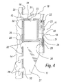
- the device 10 comprises a bracket unit 11, which is shaped so as to accommodate by resting contact and lock, by way of retention means 12, a longitudinal member 13 that is supported by at least one additional bracket unit 11.
- Each bracket unit 11 is rigidly coupled to an upright 14 by way of engagement means 15.
- bracket unit 11 is fixed to a face 16 of the upright 14 that is directed toward the outside of a shelving system, gallery or the like, the illustrated uprights 14 providing the stands thereof.
- the bracket unit 11, in this first embodiment, is constituted by a lower bracket portion 17 for support, which is adapted to support the longitudinal member 13, and by an upper bracket portion 18 for guiding and locking.
- the upper bracket portion 18 surrounds the longitudinal member 13 in an upper region.
- the lower bracket portion 17 and the upper bracket portion 18 are connected to each other by way of fastening means 19 on the side 20 of the longitudinal member 13 that is not adjacent to the upright 14.
- the fastening means 19 are constituted by a screw 21, which is inserted so that its head 22 is in abutment against a suitable first through seat 23 on the upper bracket portion 18.
- the threaded portion 24 of the screw 21 is engaged with a nut 25, which is arranged in a complementarily shaped second seat 26 on the lower bracket portion 17.
- the engagement means 15 are provided by two first hooks 28, by a second hook 29 for each one of the two comer supporting elements 27 of the lower bracket portion 17, and by a third hook 30 for each of the two cross-members 31 of the upper bracket portion 18.
- the first hooks 28, second hooks 29 and third hooks 30 enter and slide, with a reversible interlocking, in complementarily shaped slots 32 on the upright 14.
- the retention means 12 are provided by the fastening means 19 and by a tooth 33, which protrudes downward from each cross-member 31 of the upper bracket portion 18.
- the tooth 33 acts as a guide for the longitudinal member 13, which has, in an upper region, a rail 34, in which the tooth 33 engages.
- the first hooks 28 are plate-like, substantially L-shaped, and directed downward.
- the second hooks 29 are also plate-like but are hook-shaped and directed upward.
- the third plate-like hooks 30 are L-shaped and directed upward.
- the first hooks 28 directed downward allow the lower bracket portion 17 to rest on the upright 14, while the second hooks 29 prevent, by way of the upper ends 35 in abutment against the inside of the upright 14, the disengagement and the overturning of the bracket portion 17.
- the bracket portion 18 is arranged above the longitudinal member 13; therefore its third hooks 30, which are directed upward, grip an internal surface of the upright 14 that is arranged above the corresponding slots 32, preventing the disengagement and outward tipping of the bracket portion 18 and of the longitudinal member 13.
- bracket unit 111 is constituted by a semitubular vertical element 140, which is provided with means 115 for engaging the upright 114.
- a tubular body 141 cantilevers out from the vertical element 140 and extends horizontally in the direction from the upright 114 to a further nearby upright.
- the tubular body 141 acts as a support and guide for the longitudinal member 113 that passes through it.
- the tubular body 141 comprises internally a longitudinal guide 142 for a corresponding rail 143 provided on the longitudinal member 113.
- the engagement means 115 are provided by means of two male elements 145 for each side of the vertical element 140, one above the tubular body 141 and one below.
- Each male element 145 engages with a snap action on a corresponding female element 146 that is provided on the upright 114.
- Each male element 145 is provided by a stud 147 that protrudes toward the inside of the vertical element 140, while each female element 146 is provided by an opening 149 that is substantially inclined upward toward the outer face of the bracket unit 111.
- the bracket unit 111 is fixed to the upright 113 simply by inserting the stud 147 in the opening 149.
- the shape of the opening 149 and of the stud 147 cause the load placed on the bracket unit 111 to increase the grip and locking of the bracket unit 111 on the upright 114.
- the stud 147 in fact follows the opening 149, which acts as a guide for it.
- the stud 147 further, by moving downward due to the load supported by the bracket unit 111, causes said bracket unit to increase grip on the upright 114.
- the retention means are integrated in the tubular body 141.
- Said means are constituted by the guide 142, which prevents the longitudinal member 113 from performing any rotary motion about its own longitudinal axis.
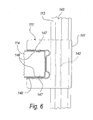
- the bracket unit here designated by the reference numeral 211, is constituted by two semitubular portions 240a and 240b: the first portion is arranged above a semitubular body 241 and the second portion is arranged below it, and said semitubular body is extended horizontally in the direction from the upright 214 to a further nearby upright.
- the semitubular portions 240a and 240b and the semitubular body 241 form a monolithic body.
- the tubular body 241 supports and guides the longitudinal member 213 that passes through it.
- the tubular body 241 comprises internally two longitudinal guides 242 for corresponding rails 243 provided on the longitudinal member 213.
- the engagement means are constituted by plate-like hook-shaped tabs 255, which are provided laterally to the semitubular portions 240a and 240b.
- the tabs 255 enter complementarily shaped slots 256 provided in the upright 214.
- the notches 257 that form the hook-like tabs 255 are substantially shaped like inverted half-Vs, thus forming on each tab 255 an inclined shoulder that is suitable to facilitate the grip of the bracket unit 211 on the upright 214 as the bracket unit 211 moves downward when loaded.
- bracket units 11, 111, 211 described by way of example are obtained at low cost from shaped, folded and worked sheet metal.
- the bracket portions 17 and 18, for example, are substantially both composed of a single piece of sheet metal, which is conveniently folded and worked.
- the three bracket units 11, 111 and 211 described here are very easy to install: the first one requires a simple screwing operation to be closed, and the second and third ones only need to be hung by means of the studs 147 and tabs 255 provided for this purpose in the respective openings 146 and slots 256, without requiring additional operations.
- the bracket units 11, 111 and 211 can be installed independently of the longitudinal element, which can therefore have any length regardless of the mutual distance at which the uprights are arranged.
- a shelving system installed with devices 10, 110, 210 according to the invention for supporting longitudinal members is therefore characterized in that the devices 10, 110, 210, for supporting the longitudinal members 13, 113 and 213 are through devices and are hung externally with respect to the uprights 14, 114, and 214 of the structure of said shelving system, designated by the reference numeral 500 in Figure 1.
- the bracket units according to the invention can therefore support very long longitudinal members, which are capable of affecting even the entire shelving system along its length.
- Such longitudinal members which in turn are independent of the bracket units, are very long and can be supported selectively either by two end bracket units or by a plurality of intermediate bracket units in addition to the two end bracket units, depending on the mutual distance at which the uprights are arranged.
- bracket units allow a same longitudinal member to rest on a plurality of bracket units in series, indeed depending on the mutual distance of the uprights from which said bracket units hang.
- a single longitudinal member that runs along the entire length of the shelving system allows to achieve a cage-like shelving system constituted by longitudinal members and shoulders that form cells suitable to interact structurally with each other.
- bracket units on the outside of the uprights allows the longitudinal members, which accordingly run on the outside of the shelving system or gallery or the like, to support shelves or pallets larger than shelving systems provided with known types of supporting device.
- Pallets or shelving systems having a larger surface advantageously imply a larger stored volume of goods.
- the present invention provides a device that is associable with longitudinal members of any length, and therefore even very long ones, even as long as to affect the entire shelving system, regardless of the number and position of the intermediate uprights arranged between the ends of said shelving system.
- the present invention provides a device that can be fixed on the outside of the uprights so that the longitudinal members can run externally with respect to them.
- the present invention provides a supporting device for longitudinal members that can be provided at low cost by working sheet metal.
- the present invention provides a supporting device for longitudinal members for which the installation operations are quick, simple to perform, and executable by personnel that is not particularly specialized.
- the present invention provides a supporting device that can be applied to uprights of a known type.
- the present invention further provides a supporting device for longitudinal members of shelving systems, galleries and the like that can be mass-produced at low cost with known systems and technologies.
- the materials employed may be any according to requirements and to the state of the art.
Landscapes
- Warehouses Or Storage Devices (AREA)
- Assembled Shelves (AREA)
Applications Claiming Priority (2)
| Application Number | Priority Date | Filing Date | Title |
|---|---|---|---|
| ITPD20030215 ITPD20030215A1 (it) | 2003-09-18 | 2003-09-18 | Dispositivo di sostegno per longheroni di scaffalature, |
| ITPD20030215 | 2003-09-18 |
Publications (2)
| Publication Number | Publication Date |
|---|---|
| EP1516560A2 true EP1516560A2 (fr) | 2005-03-23 |
| EP1516560A3 EP1516560A3 (fr) | 2006-07-26 |
Family
ID=34179341
Family Applications (1)
| Application Number | Title | Priority Date | Filing Date |
|---|---|---|---|
| EP04016119A Withdrawn EP1516560A3 (fr) | 2003-09-18 | 2004-07-08 | Dispositif de support pour des membres longitudinaux de rayonnages, galeries et similaires |
Country Status (3)
| Country | Link |
|---|---|
| EP (1) | EP1516560A3 (fr) |
| IT (1) | ITPD20030215A1 (fr) |
| RU (1) | RU2004127902A (fr) |
Family Cites Families (4)
| Publication number | Priority date | Publication date | Assignee | Title |
|---|---|---|---|---|
| US4684094A (en) * | 1984-09-10 | 1987-08-04 | Tusco Manufacturing Co. | Adjustable bracket assembly |
| US4967878A (en) * | 1989-11-14 | 1990-11-06 | Scaffold Services, Inc. | Brace for horizontal scaffold members |
| US5575444A (en) * | 1995-03-16 | 1996-11-19 | Otema; Martin | Adjustable shelf bracket |
| GB9710079D0 (en) * | 1997-05-20 | 1997-07-09 | B Mat Limited | Shelving |
-
2003
- 2003-09-18 IT ITPD20030215 patent/ITPD20030215A1/it unknown
-
2004
- 2004-07-08 EP EP04016119A patent/EP1516560A3/fr not_active Withdrawn
- 2004-09-17 RU RU2004127902/12A patent/RU2004127902A/ru not_active Application Discontinuation
Also Published As
| Publication number | Publication date |
|---|---|
| ITPD20030215A1 (it) | 2005-03-19 |
| RU2004127902A (ru) | 2006-02-20 |
| EP1516560A3 (fr) | 2006-07-26 |
Similar Documents
| Publication | Publication Date | Title |
|---|---|---|
| US4501369A (en) | Merchandise display means | |
| US10426262B2 (en) | Cantilever shelving system | |
| US5868263A (en) | Wall mounted storage system | |
| US3565381A (en) | Bracket structure | |
| JP4446108B2 (ja) | 商品の展示用のディスプレイ・デバイス | |
| US7571882B2 (en) | Suspension device comprising a profile rail that is to be vertically arranged, and comprising a bracket that can be suspended therein | |
| US20060011568A1 (en) | Track-mounted shelving systems and components | |
| CA2768320C (fr) | Dispositif de transport de marchandises concu pour recevoir et presenter des marchandises | |
| US5785189A (en) | Display shelf device having a rigid structure | |
| US20040069733A1 (en) | Hybrid shelving unit | |
| US20050199569A1 (en) | M-divider material-bay restraining cable system | |
| US2062802A (en) | Display appliance | |
| US20190246815A1 (en) | Mounting system with horizontally-slideable bracket and support bracket | |
| PL195895B1 (pl) | Układ wspornika półek | |
| CA2802725A1 (fr) | Presentoir d'articles en feuille de paletier | |
| US5725110A (en) | Space organizing system | |
| KR101797641B1 (ko) | 조립식 앵글 선반 | |
| US6471187B1 (en) | Apparatus for lifting or supporting modular furniture | |
| HK1074984A (en) | Supporting device for longitudinal members of shelving systems, galleries and the like | |
| RU2527704C1 (ru) | Колодка обеспечения устойчивости стеллажа для хранения предметов | |
| WO2004062439A1 (fr) | Systeme d'etalage | |
| US3000061A (en) | Storage building construction | |
| US6227507B1 (en) | Closet shelving system | |
| KR102089143B1 (ko) | 쇼 케이스 선반용 롤러어세이 지지장치 | |
| EP1986522B1 (fr) | Crochets pour etageres |
Legal Events
| Date | Code | Title | Description |
|---|---|---|---|
| PUAI | Public reference made under article 153(3) epc to a published international application that has entered the european phase |
Free format text: ORIGINAL CODE: 0009012 |
|
| AK | Designated contracting states |
Kind code of ref document: A2 Designated state(s): AT BE BG CH CY CZ DE DK EE ES FI FR GB GR HU IE IT LI LU MC NL PL PT RO SE SI SK TR |
|
| AX | Request for extension of the european patent |
Extension state: AL HR LT LV MK |
|
| REG | Reference to a national code |
Ref country code: HK Ref legal event code: DE Ref document number: 1074984 Country of ref document: HK |
|
| PUAL | Search report despatched |
Free format text: ORIGINAL CODE: 0009013 |
|
| AK | Designated contracting states |
Kind code of ref document: A3 Designated state(s): AT BE BG CH CY CZ DE DK EE ES FI FR GB GR HU IE IT LI LU MC NL PL PT RO SE SI SK TR |
|
| AX | Request for extension of the european patent |
Extension state: AL HR LT LV MK |
|
| AKX | Designation fees paid | ||
| REG | Reference to a national code |
Ref country code: DE Ref legal event code: 8566 |
|
| STAA | Information on the status of an ep patent application or granted ep patent |
Free format text: STATUS: THE APPLICATION IS DEEMED TO BE WITHDRAWN |
|
| 18D | Application deemed to be withdrawn |
Effective date: 20070127 |
|
| REG | Reference to a national code |
Ref country code: HK Ref legal event code: WD Ref document number: 1074984 Country of ref document: HK |